experimental setup for seismic evaluation.pdf
TRANSCRIPT
8/17/2019 Experimental Setup for Seismic Evaluation.pdf
http://slidepdf.com/reader/full/experimental-setup-for-seismic-evaluationpdf 1/33
ADDIS ABABA UNIVERSITY
AAiTDEPARTMENT OF CIVIL ENGINEERING
EXPERIMENTAL SETUP
FOR SEISMIC EVALUATION
PREPARED BY: ZEKARIAS NEJMUDIN
ID No. – GSR/1939/03
SUBMITTED TO: Dr ADIL ZEKARIA
DATE: July 18, 2011
8/17/2019 Experimental Setup for Seismic Evaluation.pdf
http://slidepdf.com/reader/full/experimental-setup-for-seismic-evaluationpdf 2/33
July 18, 2011 EXPERIMENTAL SETUP FOR SEISMIC EVALUATION
AAiT | Earthquake Engineering 4
Abstract Structural experiment plays an important role in the earthquake engineering research. Testing
and experimentation are important for seismic evaluation in the practice of mechanical vibration and
are integral in experimental modal analysis. Experimentation is testing of a preliminary design prototype
or a partial product. Measurement and associated experimental techniques play a significant role in the
practice of seismic experimentation. These experimental techniques include different mechanical
features that can simulate earthquake frequencies.
This paper explains the behavior of these mechanical features and the procedure to be followed
to take some test with them. As the most important parameter in seismic test is the pretest procedure
and the test procedure this paper describes a great deal of information on these concerts. Also most
importantly from this paper you can get an introduction to the recently used seismic testing methods,
with the aid of internet based testing.

8/17/2019 Experimental Setup for Seismic Evaluation.pdf
http://slidepdf.com/reader/full/experimental-setup-for-seismic-evaluationpdf 3/33
July 18, 2011 EXPERIMENTAL SETUP FOR SEISMIC EVALUATION
AAiT | Earthquake Engineering 5
Acknowledgement
First of all I would like to thank our generous professor Dr (ing) ADIL ZEKARIA for providing this
opportunity, so that we will refer some books or journals to come up with this paper eventually helps us
understanding the concept. Then I thank all the structural engineering stream class mates for providing
me with several information on my topic.
Finally I would add that this type of teaching process is very effective and will help in understanding
different types of concepts with small amount of time. So I would say thank you again.

8/17/2019 Experimental Setup for Seismic Evaluation.pdf
http://slidepdf.com/reader/full/experimental-setup-for-seismic-evaluationpdf 4/33
July 18, 2011 EXPERIMENTAL SETUP FOR SEISMIC EVALUATION
AAiT | Earthquake Engineering 6
Contents
Title Page number
CHAPTER 1
Introduction ………………………………………………………………………………..3
CHAPTER 2
Vibration Exciters (Shakers) …………………………………………………………5
Hydraulic shaker ………………………………………………………………………….6
Inertial shaker ……………………………………………………………………………..8
Electromagnetic shaker ……………………………………………………………….9
Control system …………………………………………………………………………….10
Motion sensors and transducers ………………………………………………….12
Torque, Force and other sensors ………………………………………………….14
CHAPTER 3
Experimental Setup for Vibration Exciters ……………………………………17
Representation of vibration environment ……………………………………17
Pretest procedures ………………………………………………………………………18
Testing procedures ……………………………………………………………………..21
CHAPTER 4
Pseudo Dynamic Test Method …………………………………………………….26
Internet based pseudo dynamic test method ………………………………27
CONCLUSION ………………………………………………………………………………29
REFERENCE ………………………………………………………………………………….30

8/17/2019 Experimental Setup for Seismic Evaluation.pdf
http://slidepdf.com/reader/full/experimental-setup-for-seismic-evaluationpdf 5/33
July 18, 2011 EXPERIMENTAL SETUP FOR SEISMIC EVALUATION
AAiT | Earthquake Engineering 7
8/17/2019 Experimental Setup for Seismic Evaluation.pdf
http://slidepdf.com/reader/full/experimental-setup-for-seismic-evaluationpdf 6/33
July 18, 2011 EXPERIMENTAL SETUP FOR SEISMIC EVALUATION
AAiT | Earthquake Engineering 8
CHAPTER 1
INTRODUCTIONStructural experiment plays an important role in the earthquake engineering research. Testing
and experimentation are important for seismic evaluation in the practice of mechanical vibration and
are integral in experimental modal analysis. Experimentation is testing of a preliminary design prototype
or a partial product. Measurement and associated experimental techniques play a significant role in the
practice of vibration.
Recently, some research efforts have been made on developing the technology of collaborative
structural experiments. In view of the continuous changes in structural engineering and the increasing
awareness of cost in today’s society, the existing large-sized structural laboratories are gradually
becoming incapable of satisfying the various types of demand of the experiments.
Design and development of a product
Testing (screening) of a finished product for quality assurance
Qualification of a good-quality product to determine its suitability for a specific application
Mechanical aging of a product prior to carrying out a test program
Exploratory testing of a product to determine its dynamic characteristic such as resonances,
mode shapes, and even a complete dynamic model.
Vibration monitoring for performance evaluation
Control and suppression of vibration.
In some experimental procedures (primarily in vibration testing), the excitation signal must begenerated in a signal generator, in accordance with some requirement (specification), and applied to the
object through an exciter after amplification and conditioning. Vibration testing is usually performed by
applying a vibratory excitation to a test object and monitoring the structural integrity and performance
of the intended function of the object. The technology of vibration testing has rapidly evolved since
World War II, and the technique has been successfully applied to a wide spectrum of products ranging
from small printed circuit boards and microprocessor chips to large missiles and structural systems
Today’s complex test programs require the capability of fast and accurate processing of large
numbers of measurements. The most uncertain part of a vibration test program is the simulation of the
test input. As another example, in seismic qualification of equipment, the primary difficulty stems from
the fact that the probability of accurately predicting the recurrence of an earthquake at a given siteduring the design life of the equipment is very small, and that of predicting the nature of the ground
motions if an earthquake were to occur is even smaller. In this case, the best that one could do would be
to make a conservative estimate of the nature of the ground motions due to the strongest earthquake
that is reasonably expected. The test input should have:
8/17/2019 Experimental Setup for Seismic Evaluation.pdf
http://slidepdf.com/reader/full/experimental-setup-for-seismic-evaluationpdf 7/33
July 18, 2011 EXPERIMENTAL SETUP FOR SEISMIC EVALUATION
AAiT | Earthquake Engineering 9
(1) Amplitude,
(2) Phasing,
(3) Frequency content , and
(4) Damping characteristics comparable to the expected vibration environment, if satisfactory
representation is to be achieved.
The two primary steps of a vibration testing scheme are:
Step 1: Specify the test requirements.
Step 2: Generate a vibration test signal that conservatively satisfies the specifications of step 1.
Test environment
Based on the vibration-testing specifications or product qualification requirements, the test
environment should be developed to have the required characteristics of:
(1) Intensity (amplitude);
(2) Frequency content (effect on the test-object resonances and the like);
(3) Decay rate (damping); and(4) Phasing (dynamic interactions).
Usually, these parameters are chosen to conservatively represent the worst possible vibration
environment that is reasonably expected during the design life of the test object. So long as this
requirement is satisfied, it is not necessary for the test environment to be identical to the operating
vibration environment.
It follows that instrumentation in experimental vibration can be generally classified into the
following categories:
1. Signal-generating devices
2. Vibration exciters
3. Sensors and transducers
4. Signal conditioning/modifying devices5. Signal analysis devices
6. Control devices
7. Vibration recording and display devices.
An experimental vibration system generally consists of four main subsystems:
1. Test object
2. Excitation system
3. Control system
4. Signal acquisition and modification system
Experimental research in earthquake engineering and structural dynamics is currently carried out usingseveral types of facility, some of them are:
Vibration shake tables
Pseudo-dynamic test
Cyclic loading test
8/17/2019 Experimental Setup for Seismic Evaluation.pdf
http://slidepdf.com/reader/full/experimental-setup-for-seismic-evaluationpdf 8/33
July 18, 2011 EXPERIMENTAL SETUP FOR SEISMIC EVALUATION
AAiT | Earthquake Engineering 10
CHAPTER 2
VIBRATION EXCITERS (SHAKERS)
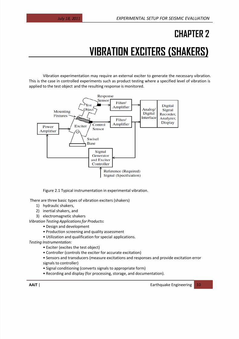
Vibration experimentation may require an external exciter to generate the necessary vibration.
This is the case in controlled experiments such as product testing where a specified level of vibration is
applied to the test object and the resulting response is monitored.
Figure 2.1 Typical instrumentation in experimental vibration.
There are three basic types of vibration exciters (shakers)
1) hydraulic shakers,
2) inertial shakers, and
3) electromagnetic shakers
Vibration Testing Applications for Products:
• Design and development
• Production screening and quality assessment
• Utilization and qualification for special applications. Testing Instrumentation:
• Exciter (excites the test object)
• Controller (controls the exciter for accurate excitation)
• Sensors and transducers (measure excitations and responses and provide excitation error
signals to controller)
• Signal conditioning (converts signals to appropriate form)
• Recording and display (for processing, storage, and documentation).

8/17/2019 Experimental Setup for Seismic Evaluation.pdf
http://slidepdf.com/reader/full/experimental-setup-for-seismic-evaluationpdf 9/33
July 18, 2011 EXPERIMENTAL SETUP FOR SEISMIC EVALUATION
AAiT | Earthquake Engineering 11
Table 2.1 Typical Operation-Capability Ranges for Various Shaker Types
SHAKERS
A shake is a dynamic earthquake simulator that can “re-play” the record of earthquake motions
from a past earthquake or vibrate to represent expected future ground motions. Shakers produce a
shock or vibration when a force, a position, a velocity, or acceleration is abruptly modified and creates a
transient state in the system considered. The modification is normally regarded as abrupt if it occurs in a
time period that is short compared with the natural period concerned (AFNOR, 1993). Shock is defined
as a vibratory excitation having duration between the natural period of the excited mechanical system
and two times that period. As I have said previously shakers are classified into three basic types.
2.1 Hydraulic shaker
A typical hydraulic shaker consists of a piston-cylinder arrangement called a ram, a servo-valve,
a fluid pump, and a driving electric motor. Hydraulic fluid or oil is pressurized with typical operating
pressure: 27.58 Mpa and pumped into the cylinder through a servo-valve by means of a pump that is
driven by an electric motor with typical power, 150 hp). The flow has typical rate: 378.54 Liters/min that
enters the cylinder is controlled or modulated by the servo-valve, which in effect, controls the resulting
piston or ram motion. A typical servo-valve consists of a two-stage spool valve, which provides a
pressure difference and a controlled or modulated flow to the piston, which sets it in motion. A primary
function of the servo-valve is to provide a stabilizing feedback to the ram. In this respect, the servo-valvecomplements the main control system of the test setup. The ram is coupled to the shaker table by
means of a link with some flexibility. The cylinder frame is mounted on the support foundation with
swivel joints.

8/17/2019 Experimental Setup for Seismic Evaluation.pdf
http://slidepdf.com/reader/full/experimental-setup-for-seismic-evaluationpdf 10/33
July 18, 2011 EXPERIMENTAL SETUP FOR SEISMIC EVALUATION
AAiT | Earthquake Engineering 12
Figure 2.1.2 basic components of a typical hydraulic shaker: (a) schematic diagram; (b) operational block
diagram.
If the test table is directly supported on the vertical actuators, they must withstand the total dead
weight (i.e., the weight of the test table, the test object, the mounting fixtures, and the
instrumentation). It is desirable to locate the actuators at the floor level in the test laboratory so that to
minimize the effort required placing the test object on the test table.Components of a hydraulic shaking table:
The plate
Actuator
Servo valves
accumulators
hydraulic pumps
piping system
cooling system
Controllers and associated sensors.
Figure 2.1.3 typical hydraulic actuator
Hydraulic actuators are most suitable for heavy load testing and are widely used in industrial and
civil engineering applications. They can be operated at very low frequencies (almost direct current [DC]),as well as at intermediate frequencies.
Advantages of hydraulic shaker
high flexibility of operation
wide band random input
limited cost
important force or power
8/17/2019 Experimental Setup for Seismic Evaluation.pdf
http://slidepdf.com/reader/full/experimental-setup-for-seismic-evaluationpdf 11/33
July 18, 2011 EXPERIMENTAL SETUP FOR SEISMIC EVALUATION
AAiT | Earthquake Engineering 13
Disadvantages of hydraulic shaker
low frequency
low velocity
For seismic tests, all laboratories use hydraulic shakers because it is necessary to have important forces
at low frequency.
2.2. Inertial shakers
In inertial shakers, or “mechanical exciters,” the force that causes the shaker-table motion is
generated by inertia forces (accelerating masses). Counter-rotating-mass inertial shakers are typical in
this category. To understand their principle of operation, consider two equal masses rotating in opposite
directions at the same angular speed and in the same circle of radius r. This produces a resultant force
equal to 2m2r cos t in a fixed direction (the direction of symmetry of the two rotating arms).
Consequently, a sinusoidal force with a frequency of and amplitude proportional to 2 is generated.
This reaction force is applied to the shaker table.
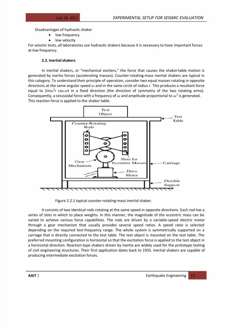
Figure 2.2.1 typical counter-rotating-mass inertial shaker.
It consists of two identical rods rotating at the same speed in opposite directions. Each rod has a
series of slots in which to place weights. In this manner, the magnitude of the eccentric mass can be
varied to achieve various force capabilities. The rods are driven by a variable-speed electric motor
through a gear mechanism that usually provides several speed ratios. A speed ratio is selected
depending on the required test-frequency range. The whole system is symmetrically supported on acarriage that is directly connected to the test table. The test object is mounted on the test table. The
preferred mounting configuration is horizontal so that the excitation force is applied to the test object in
a horizontal direction. Reaction-type shakers driven by inertia are widely used for the prototype testing
of civil engineering structures. Their first application dates back to 1935. Inertial shakers are capable of
producing intermediate excitation forces.
8/17/2019 Experimental Setup for Seismic Evaluation.pdf
http://slidepdf.com/reader/full/experimental-setup-for-seismic-evaluationpdf 12/33
July 18, 2011 EXPERIMENTAL SETUP FOR SEISMIC EVALUATION
AAiT | Earthquake Engineering 14
Advantages of inertial shakers
intermediate forces
low displacement capabilities
intermediate velocity and acceleration
exclusively sinusoidal excitation force
Disadvantages of inertial shakers
no complex or random excitation
no constant force testing
flexibility to vary the force
flexibility to vary displacement
The sinusoidal excitation generated by inertial shakers is virtually undistorted, which gives them an
advantage over the other types of shakers when used in sine-dwell and sine-sweep tests.
2.3. Electromagnetic Shakers
In electromagnetic shakers or “electrodynamics exciters,” the motion is generated using the principle of
operation of an electric motor. Specifically, the excitation force is produced when a variable excitation
signal (electrical) is passed through a moving coil placed in a magnetic field.
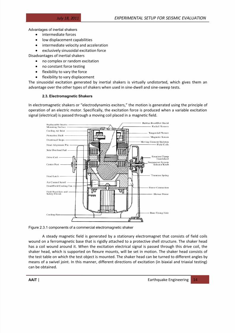
Figure 2.3.1 components of a commercial electromagnetic shaker
A steady magnetic field is generated by a stationary electromagnet that consists of field coils
wound on a ferromagnetic base that is rigidly attached to a protective shell structure. The shaker head
has a coil wound around it. When the excitation electrical signal is passed through this drive coil, the
shaker head, which is supported on flexure mounts, will be set in motion. The shaker head consists of
the test table on which the test object is mounted. The shaker head can be turned to different angles by
means of a swivel joint. In this manner, different directions of excitation (in biaxial and triaxial testing)
can be obtained.

8/17/2019 Experimental Setup for Seismic Evaluation.pdf
http://slidepdf.com/reader/full/experimental-setup-for-seismic-evaluationpdf 13/33
July 18, 2011 EXPERIMENTAL SETUP FOR SEISMIC EVALUATION
AAiT | Earthquake Engineering 15
Advantages of electromagnetic shakers
high frequency range
high degree of operating flexibility
high level of accuracy of the generated shaker motion
Disadvantages of electromagnetic shakers
not suitable for heavy-duty applications(large test objects) cement and velocity capabilities are limited to low or intermediate values
very expensive
2.4 Transient Exciters
Other varieties of exciters are commonly used in transient-type vibration testing. In these tests, either
an impulsive force or an initial excitation is applied to the test object and the resulting response is
monitored. The excitations and the responses are “transient” in this case. Some examples of transient
exciters can be seen below. Hammer test, drop tests, and pluck tests fall into this category.
Hammer test
Hammer test may be conducted by hitting the object with an instrumented hammer and thenmeasuring the response of the object. The hammer has a force sensor at its tip, as shown in the figure
below.
Figure 2.4.1 An instrumented hammer used in hammer tests.
Piezoelectric or strain-gage type force sensor may be used. More sophisticated hammers have
impedance heads in place of force sensors. An impedance head measures force and acceleration
simultaneously. The results of a hammer test will depend on many factors; for example, the dynamics of
the hammer body, how firmly the hammer is held during the impact, how quickly the impact is applied,
and whether there are multiple impacts.
2.5 Control System
The two primary functions of the shaker control system in vibration testing are (1) to guarantee
that the specified excitation is applied to the test object and (2) to ensure that the dynamic stability
(motion constraints) of the test setup is preserved. An operational block diagram illustrating these
control functions is given in the figure below. The reference input to the control system represents the
desired excitation force that should be applied to the test object. In the absence of any control,
however, the force reaching the test object will be distorted, primarily because of:
8/17/2019 Experimental Setup for Seismic Evaluation.pdf
http://slidepdf.com/reader/full/experimental-setup-for-seismic-evaluationpdf 14/33
July 18, 2011 EXPERIMENTAL SETUP FOR SEISMIC EVALUATION
AAiT | Earthquake Engineering 16
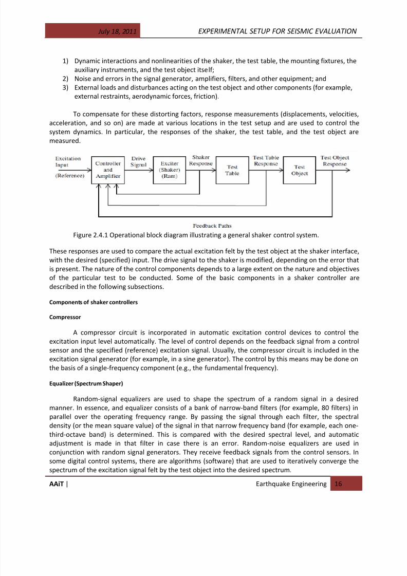
1) Dynamic interactions and nonlinearities of the shaker, the test table, the mounting fixtures, the
auxiliary instruments, and the test object itself;
2) Noise and errors in the signal generator, amplifiers, filters, and other equipment; and
3) External loads and disturbances acting on the test object and other components (for example,
external restraints, aerodynamic forces, friction).
To compensate for these distorting factors, response measurements (displacements, velocities,
acceleration, and so on) are made at various locations in the test setup and are used to control the
system dynamics. In particular, the responses of the shaker, the test table, and the test object are
measured.
Figure 2.4.1 Operational block diagram illustrating a general shaker control system.
These responses are used to compare the actual excitation felt by the test object at the shaker interface,
with the desired (specified) input. The drive signal to the shaker is modified, depending on the error that
is present. The nature of the control components depends to a large extent on the nature and objectives
of the particular test to be conducted. Some of the basic components in a shaker controller are
described in the following subsections.
Components of shaker controllers
Compressor
A compressor circuit is incorporated in automatic excitation control devices to control the
excitation input level automatically. The level of control depends on the feedback signal from a control
sensor and the specified (reference) excitation signal. Usually, the compressor circuit is included in the
excitation signal generator (for example, in a sine generator). The control by this means may be done on
the basis of a single-frequency component (e.g., the fundamental frequency).
Equalizer (Spectrum Shaper)
Random-signal equalizers are used to shape the spectrum of a random signal in a desired
manner. In essence, and equalizer consists of a bank of narrow-band filters (for example, 80 filters) in
parallel over the operating frequency range. By passing the signal through each filter, the spectral
density (or the mean square value) of the signal in that narrow frequency band (for example, each one-
third-octave band) is determined. This is compared with the desired spectral level, and automatic
adjustment is made in that filter in case there is an error. Random-noise equalizers are used in
conjunction with random signal generators. They receive feedback signals from the control sensors. In
some digital control systems, there are algorithms (software) that are used to iteratively converge the
spectrum of the excitation signal felt by the test object into the desired spectrum.
8/17/2019 Experimental Setup for Seismic Evaluation.pdf
http://slidepdf.com/reader/full/experimental-setup-for-seismic-evaluationpdf 15/33
July 18, 2011 EXPERIMENTAL SETUP FOR SEISMIC EVALUATION
AAiT | Earthquake Engineering 17
Tracking Filter
Many vibration tests are based on single-frequency excitations. In such cases, the control
functions should be performed on the basis of the amplitudes of the fundamental-frequency component
of the signal. A tracking filter is simply a frequency-tuned band-pass filter. It automatically tunes the
center frequency of its very narrow-band-pass filter to the frequency of a carrier signal. Then, when a
noisy signal is passed through the tuned filter, the output of the filter will be the required fundamentalfrequency component in the signal.
Excitation Controller (Amplitude Servo-Monitor)
An excitation controller is typically an integral part of the signal generator. It can be set so that
automatic sweep between two frequency limits can be performed at a selected sweep rate (linear or
logarithmic). More advanced excitation controllers have the capability of an automatic switch-over
between constant displacement, constant-velocity and constant-acceleration excitation-input control at
specified frequencies over the sweep frequency interval.
2.6 Motion sensors and transducers
Motion sensing is considered the most important measurement in vibration applications. Other
variables, such as force, torque, stress, strain, and material properties, are also important, either directly
or indirectly, in the study of vibration. This section will describe some useful measuring devices of
motion in the field of mechanical vibration.
A transducer is a devise that converts one type of energy to another. Transducers are the input element
in a measurement system. The transducer is the device sensing the physical quantity that is to be
measured and producing an electrical output. A transducer may contain one or more sensors which
transmit a signal to a measurement unit producing the electric output.
2.6.1 Potentiometer
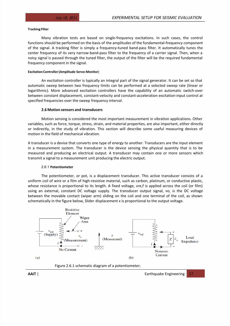
The potentiometer, or pot, is a displacement transducer. This active transducer consists of a
uniform coil of wire or a film of high-resistive material, such as carbon, platinum, or conductive plastic,
whose resistance is proportional to its length. A fixed voltage, vre,f is applied across the coil (or film)
using an external, constant DC voltage supply. The transducer output signal, vo, is the DC voltage
between the movable contact (wiper arm) sliding on the coil and one terminal of the coil, as shown
schematically in the figure below, Slider displacement x is proportional to the output voltage.
Figure 2.6.1 schematic diagram of a potentiometer;
8/17/2019 Experimental Setup for Seismic Evaluation.pdf
http://slidepdf.com/reader/full/experimental-setup-for-seismic-evaluationpdf 16/33
July 18, 2011 EXPERIMENTAL SETUP FOR SEISMIC EVALUATION
AAiT | Earthquake Engineering 18
Linear potentiometers are devices allowing to transduce linear displacements. They have three
connectors: ground, v supply and v output connector. Resistance- based potentiometers may use a wire
winding around cylindrical core or a thin carbon layer as resistors. The output connector may translate
and is rigidly attached to the object whose displacement we want to measure. The displacement of the
object of interest therefore causes a displacement of the cursor on the resistor(x), which causes a
change in the output voltage of the pot.
2.6.2 Variable-Inductance Transducers
Motion transducers that employ the principle of electromagnetic induction are termed variable
inductance transducers. When the flux linkage (defined as magnetic flux density times the number of
turns in the conductor) through an electrical conductor changes, a voltage is induced in the conductor.
This, in turn, generates a magnetic field that opposes the primary field. Hence, a mechanical force is
necessary to sustain the change of flux linkage. If the change in flux linkage is brought about by a
relative motion, the mechanical energy is directly converted (induced) into electrical energy. This is the
basis of electromagnetic induction, and it is the principle of operation of electrical generators and
variable inductance transducers. The induced voltage or change in inductance may be used as a measureof the motion.
There are many different types of variable-inductance transducers. One of the types is discussed
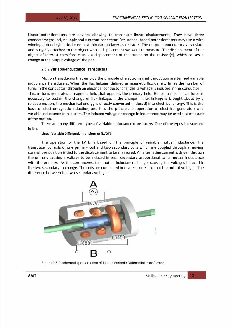
below.Linear Variable Differential transformer (LVDT)
The operation of the LVTD is based on the principle of variable mutual inductance. The
transducer consists of one primary coil and two secondary coils which are coupled through a moving
core whose position is tied to the displacement to be measured. An alternating current is driven through
the primary causing a voltage to be induced in each secondary proportional to its mutual inductance
with the primary. As the core moves, this mutual inductance change, causing the voltages induced in
the two secondary to change. The coils are connected in reverse series, so that the output voltage is the
difference between the two secondary voltages.
Figure 2.6.2 schematic presentation of Linear Variable Differential transformer

8/17/2019 Experimental Setup for Seismic Evaluation.pdf
http://slidepdf.com/reader/full/experimental-setup-for-seismic-evaluationpdf 17/33
July 18, 2011 EXPERIMENTAL SETUP FOR SEISMIC EVALUATION
AAiT | Earthquake Engineering 19
LVDT principles
2.7 Torque, Force, and Other Sensors
The forced vibrations in a mechanical system depend on the forces and torques (excitations)
applied to the system. Also, the performance of the system may be specified in terms of forces and
torques that are generated, as for machine-tool operations such as grinding, cutting, forging, extrusion,
and rolling. Performance monitoring and evaluation, failure detection and diagnosis, and vibration
testing may depend considerably on the accurate measurement of associated forces and torques. In
mechanical applications such as parts assembly, slight errors in motion can generate large forces and
torques. These observations highlight the importance of measuring forces and torques. The strain gage
is a sensor that is commonly used in this context. There are numerous other types of sensors and
transducers that are useful in the context of mechanical vibration. In this section, we will outline several
of these sensors.
2.7.1 Strain Gage Sensors
Many types of force and torque sensors, as well as motion sensors such as accelerometers, arebased on strain gage measurements. Hence, strain gages are very useful in vibration instrumentation.
Although strain gages measure strain, the measurements can be directly related to stress and force.
Note, however, that strain gages may be used in a somewhat indirect manner, using auxiliary front-end
elements, to measure other types of variables, including displacement and acceleration.
2.7.2 Force and Torque Sensors
Torque and force sensing is useful in vibration applications, including the following:
1) In vibration control of machinery where a small motion error can cause large damaging forces or
performance degradation.
2) In high-speed vibration control when motion feedback alone is not fast enough (here, forcefeedback and feed forward force control can be used to improve the accuracy and bandwidth).
3) In vibration testing, monitoring, an diagnostic applications, where torque and force sensing can
detect, predict, and identify abnormal operation, malfunction, component failure, or excessive
wear (e.g., in monitoring machine tools such as milling machines and drills).
4) In experimental modal analysis where both excitation forces and response motioning may be
needed to experimentally determine the system model.
8/17/2019 Experimental Setup for Seismic Evaluation.pdf
http://slidepdf.com/reader/full/experimental-setup-for-seismic-evaluationpdf 18/33
July 18, 2011 EXPERIMENTAL SETUP FOR SEISMIC EVALUATION
AAiT | Earthquake Engineering 20
In most applications, torque (or force) is sensed by detecting either an effect or the cause of
torque (or force). There are also methods for measuring torque (or force) directly. Common methods of
torque sensing include the following:
1) Measuring the strain in a sensing member between the drive element and the driven load,
using a strain gage bridge.
2) Measuring the displacement in a sensing member (as in the first method), either directly, using
a displacement sensor, or indirectly, by measuring a variable, such as magnetic inductance or
capacitance, that varies with displacement.
3) Measuring the reaction in the support structure or housing (by measuring a force) and the
associated lever arm length.
4) In electric motors, measuring the field or armature current that produces motor torque; in
hydraulic or pneumatic actuators, measuring the actuator pressure.
5) Measuring the torque directly, for example, using piezoelectric sensors.
6) Employing the servo method to balance the unknown torque with a feedback torque generated
by an active device (say, a servomotor) whose torque characteristics are known precisely.
7) Measuring the angular acceleration in a known inertia element when the unknown torque is
applied.
2.7.3 Deflection Torque Sensors
Instead of measuring strain in the sensor element, the actual deflection (twisting or bending)
can be measured and used to determine torque, through a suitable calibration constant. For a circular-
shaft (solid or hollow) torsion element, the governing relationship is given by
=
The calibration constant GJ/L must be small in order to achieve high sensitivity. This means that
the element stiffness should be low. This will limit the bandwidth (which measures speed of response)
and gain (which determines steady-state error) of the overall system. The twist angle, u, is very small
(e.g., a fraction of a degree) in systems with high bandwidth. This requires very accurate measurement
of u in order to determine the torque T.
2.7.4 Reaction Torque Sensors
The foregoing methods of torque sensing use a sensing element that is connected between the
drive member and the driven member. A major drawback of such an arrangement is that the sensing
element modifies the original system in an undesirable manner, particularly by decreasing the system
stiffness and adding inertia. Not only will the overall bandwidth of the system decrease, but the original
torque will also be changed (mechanical loading) because of the inclusion of an auxiliary sensing
element. Furthermore, under dynamic conditions, the sensing element will be in motion, thereby
making the torque measurement more difficult. The reaction method of torque sensing eliminates these
problems to a large degree. This method can be used to measure torque in a rotating machine. The
supporting structure (or housing) of the rotating machine (e.g., a motor, pump, compressor, turbine, or
generator) is cradled by releasing its fixtures, and the effort necessary to keep the structure from
moving is measured. A schematic representation of the method is shown in figure below.
8/17/2019 Experimental Setup for Seismic Evaluation.pdf
http://slidepdf.com/reader/full/experimental-setup-for-seismic-evaluationpdf 19/33
July 18, 2011 EXPERIMENTAL SETUP FOR SEISMIC EVALUATION
AAiT | Earthquake Engineering 21
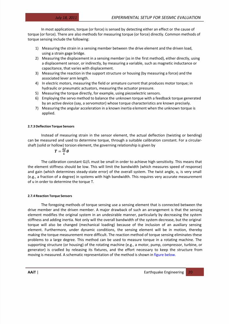
Ideally, a lever arm is mounted on the cradled housing, and the force required to fix the housing
is measured using a force sensor (load cell). The reaction torque on the housing is given by:
TR = FR·L
Where
FR = reaction force measured using load cellL = lever arm length
Figure 2.7.1 schematic representation a reaction torque sensor setup
8/17/2019 Experimental Setup for Seismic Evaluation.pdf
http://slidepdf.com/reader/full/experimental-setup-for-seismic-evaluationpdf 20/33
July 18, 2011 EXPERIMENTAL SETUP FOR SEISMIC EVALUATION
AAiT | Earthquake Engineering 22
CHAPTER 3
EXPERIMENTAL SETUP OF VIBRATION EXCITERS
Vibration testing is usually performed by applying a vibratory excitation to a test object and
monitoring the structural integrity of the object and its performance of its intended function. The
technique may be useful in several stages:
(1) Design development,
(2) Production, and
(3) Utilization of a product.
In the initial design stage, the design weaknesses and possible improvements can be determined
through the vibration testing of a preliminary design prototype or a partial product.
Vibration testing is usually accomplished using a shaker apparatus. The test object is secured to
the shaker table in a manner representative of its installation during actual use (service). In-service
operating conditions are simulated while the shaker table is actuated by applying a suitable input signal.
The shakers of different types, with electromagnetic, electromechanical, or hydraulic actuators, are
available. The shaker device may depend on the test requirement, availability, and cost. More than one
signal may be required to simulate three-dimensional characteristics of the vibration environment. The
test input signal is either stored on an analog magnetic tape or generated in real-time by a signal
generator.
The excitation signal is applied to the shaker through a shaker controller, which usually has a
built-in power amplifier. The shaker controller compares the “control sensor” signal from the shaker –
test object interface with the reference excitation signal from the signal generator. The associated error
is used to control the shaker motion so as to push this error to zero. This is termed “equalization.”
Hence, a shaker controller serves as an equalizer as well.
3.2 Representation of a Vibration Environment
A complete knowledge of the vibration environment in which a device will be operating is not
available to the test engineer or the test program planner. The primary reason for this is that the
operating environment is a random process. When performing a vibration test, however, either a
deterministic or a random excitation can be employed to meet the test requirements. This is known as
the test environment. Based on the vibration-testing specifications or product qualification
requirements, the test environment should be developed to have the required characteristics of
(1) Intensity (amplitude),
(2) Frequency content (effect on the test-object resonances and the like),
(3) Decay rate (damping), and
(4) Phasing (dynamic interactions).
Usually, these parameters are chosen to represent conservatively the worst possible vibration
environment that is reasonably expected during the design life of the test object. So long as this
requirement is satisfied, it is not necessary for the test environment to be identical to the operating
vibration environment.
8/17/2019 Experimental Setup for Seismic Evaluation.pdf
http://slidepdf.com/reader/full/experimental-setup-for-seismic-evaluationpdf 21/33
July 18, 2011 EXPERIMENTAL SETUP FOR SEISMIC EVALUATION
AAiT | Earthquake Engineering 23
In vibration testing, the excitation input (test environment) can be represented in several ways.
The common representations are:
(1) by time signal,
(2) by response spectrum,
(3) by Fourier spectrum, and
(4) by PSD function. Once the required environment is specified by one of these forms, the test
should be conducted either by directly employing them to drive the exciter or by using a more
conservative excitation when the required environment cannot be exactly reproduced.
3.3 Pretest Procedures
The selection of a test procedure for the vibration testing of an object should be based on
technical information regarding the test object and its intended use. Vendors usually prefer to use more
established, conventional testing methods and are generally reluctant to incorporate modifications and
improvements. This is primarily due to economic reasons, convenience, testing-time limitation,
availability of the equipment and facilities (test-lab limitations), and similar factors. Regulatory agencies,
however, usually modify their guidelines from time to time, and some of these requirements are
mandatory. Before conducting a vibration test on a test object, it is necessary to follow several pretestprocedures. Such procedures are necessary in order to conduct a meaningful test. Some important
pretest procedures include the following:
1. Understanding the purpose of the test
2. Studying the service functions of the test object
3. Acquiring information on the test object
4. Planning the test program
5. Conducting pretest inspection of the test object
6. Resonance-searching to gather dynamic information about the test object
7. Mechanically aging the test object
In the following sections, we shall discuss each of the first five items of these procedures to emphasize
how they can contribute to a meaningful test.
3.3.1 Purpose of Testing
As noted before, vibration testing is useful in various stages of
(1) Design and development,
(2) Production and quality assurance, and
(3) Qualification and utilization of a product.
Depending on the outcome of a vibration test, design modifications or corrective actions can be
recommended for a preliminary design or a partial product. Vibration testing can be employed todetermine vibration-isolation material requirements in structures for providing adequate damping. Such
tests fall into the first category of system development tests. They are beneficial for the designer and
the manufacturer in improving the quality of performance of the product.
For special-purpose products, it is sometimes also necessary to conduct a vibration test on the
final product before its installation for service operation. For mass-produced items, it is customary to
select representative samples form each batch of the product for these tests. The purpose of such test is
8/17/2019 Experimental Setup for Seismic Evaluation.pdf
http://slidepdf.com/reader/full/experimental-setup-for-seismic-evaluationpdf 22/33
July 18, 2011 EXPERIMENTAL SETUP FOR SEISMIC EVALUATION
AAiT | Earthquake Engineering 24
to detect any inferiority in the workmanship or in the materials used. These tests fall into the second
category, quality-assurance tests. These usually consist of a standard series of routine tests that are well
established for a given product.
Distribution qualification and seismic qualification of devices and components are good
examples of the use of the third category, qualification tests. A high-quality product such as a valve
actuator, for instance, which is thoroughly tested in the design-development stage and at the final
production stage, will need further dynamic tests or analysis if it is to be installed in a nuclear power
plant. The purpose in this testing is to determine whether the product (valve actuator) will be crucial for
system-safety-related functions. The purpose of any vibration test should be clearly understood before
incorporating it into a test program. A particular test might be meaningless under some circumstances.
3.3.2 Service Functions
For product qualification by testing, it is required that the test object remain functional and
maintain its structural integrity when subjected to a certain prespecified dynamic environment. In
seismic qualification of equipment, for instance, the dynamic environment is an excitation that
adequately represents the amplitude, phasing, frequency content, and transient characteristics (decay
rate and signal duration) of the motions at the equipment-support locations, caused by the most severe
seismic disturbance that has a reasonable probability of occurring during the design life of the
equipment. Monitoring the proper performance of in-service functions (functional-operability
monitoring) of a test object during vibration testing can be crucial in the qualification decision. The
intended service functions of the test object should be clearly defined prior to testing. For active
equipment, functional operability is necessary during vibration testing. For passive equipment, however,
only structural integrity need be maintained during testing.
3.3.3 Information Acquisition
In addition to information concerning service functions, as discussed in the previous section, and
dynamic characteristics determined from a resonance search, as will be discussed later in this chapter,
there are other characteristics of the test object that need to be studied in the development of a
vibration testing program. In particular, there are characteristics that cannot be described in exact
quantitative terms. In determining the value of a piece of equipment, for instance, the monetary value
(or cost) might be relatively easy to estimate, whereas it can be very difficult to assign a dollar value to
its significance under service conditions. One reason for this is that a particular piece of equipment
alone may not determine the proper operation of a complex system. Interaction of a particular unit with
other subsystems in a complex operation would determine the importance attached to it and, hence, its
value. In this sense, the true value of a test object is a relatively complex consideration. The service
function of the test object is also an important consideration in determining its value. The value of a test
object is important in planning a test program, because the cost of a test program and the effort
expended therein are governed mainly by this factor.
Many features of a test object that are significant in planning a test program can be deduced
from manufacturer’s data for the particular object. The following information is representative:
8/17/2019 Experimental Setup for Seismic Evaluation.pdf
http://slidepdf.com/reader/full/experimental-setup-for-seismic-evaluationpdf 23/33
July 18, 2011 EXPERIMENTAL SETUP FOR SEISMIC EVALUATION
AAiT | Earthquake Engineering 25
1) Drawings (schematic or to scale when appropriate) of principal components and the whole
assembly, with the manufacturer’s name, identification numbers, and dimensions clearly
indicated
2) Materials used, design strengths, fatigue life, and so on, of various components, and factors
determining the structural integrity of the unit
3) Component weight and total weight of the unit
4) Design ratings, capacities, and tolerances for in-service operation of each crucial component
5) Description of the intended functions of each component and of the entire unit, clearly
indicating the parameters that determine functional operability of the unit
6) Interface details (inter-component as well as for the entire assembly), including in-service
mounting configurations and mounting details
7) Details of the probable operating site or operating environment (particularly with respect to the
excitation events if product qualification is intended)
8) Details of any previous testing or analysis performed on that unit or a similar one
3.3.4. Test-Program Planning
The test program to which a test object is subjected depends on several factors including the following:
1) The objectives and specific requirements of the test
2) In-service conditions, including equipment-mounting features, the vibration environment, and
specifications of the test environment
3) The nature of the test object, including complexity, assembly level, and functional-operability
parameters to be monitored
4) Test-laboratory capabilities, available testing apparatus, past experience, conventions, and
established practices of testing
Initially, it is not necessary to develop a detailed test procedure; this is required only at the stage of
actual testing. In the initial stage it is only necessary to select the appropriate test method, based on
factors such as those listed in the beginning of this section. Before conducting the tests, however, a testprocedure should be prepared in sufficient detail. In essence, this is a pretest requirement.
Objectives and specific requirements of a test depend on such considerations as whether the test is
conducted at the design stage, the quality-control stage or the utilization stage.
If it is necessary to qualify the test object for several different dynamic environments, a generic
test that represents (conservatively, but without the risk of over testing) all these environments could
be used. For this purpose, special test-excitation inputs must be generated, taking into account the
variability of the excitation characteristics under the given set of environments. Another important
consideration in planning a test program is the required accuracy for the test, including the accuracy for
the excitation inputs, response and operability measurements, and analysis. This is related to the value
of the test object and the objectives of the test.
When planning a test procedure, we should clearly identify the standards, government
regulations, and specifications that are applicable to a particular test. The pertinent sections of the
applicable documents should be noted, and proper justification should be given if the tests deviate from
regulatory-agency requirements.
Test plans prepared in the pretest stage should include an adequate description of the following
important items:

8/17/2019 Experimental Setup for Seismic Evaluation.pdf
http://slidepdf.com/reader/full/experimental-setup-for-seismic-evaluationpdf 24/33
July 18, 2011 EXPERIMENTAL SETUP FOR SEISMIC EVALUATION
AAiT | Earthquake Engineering 26
1. Test purpose
2. Test-object details
3. Test environment, specifications, and standards
4. Functional-operability parameters and failure or malfunction criteria
5. Pretest inspection
6. Aging requirements
7. Test outline
8. Instrumentation requirements
9. Data-processing requirements
10. Methods of evaluation of the test results
3.3.5 Pretest Inspection
Pretest inspection of a test object is important at least for two major reasons. First, if the
equipment supplied for testing is different from the piece of equipment or the group of equipment that
is required to be qualified, then these differences must be carefully observed and recorded in sufficient
detail. In particular, deviations in the model number, mounting features and other details of themechanical interface, geometry, size, and significant dynamic features should be recorded. Second,
before testing, the test object should be inspected for any damage, deficiencies, or malfunctions.
Structural integrity usually can be determined by visual inspection alone. To determine malfunctions by
operability monitoring, however, the test object must be actuated and the operating environment
should be simulated. If the equipment supplied for testing is not identical to that required to be tested,
adequate justification must be provided for the differences to guarantee that the objectives of the test
can be achieved by testing the equipment that is supplied. Otherwise, the test should be abandoned
pending the arrival of the correct test object.
If any structural failure or operation malfunction is noted during pretest inspection, no
corrective action should be taken by the test laboratory personnel unless those actions are notified to
and fully authorized by the supplier of the test object.
3.4 Testing Procedures
Vibration testing may involve pretesting prior to the main tests. The objectives of pretesting may be:
1) Exploratory, in order to obtain dynamic information such as natural frequencies, mode shapes
and damping about the test object;
2) Preconditioning, in order to age or pass the “infant-mortality” stage so that the main test will be
realistic and correspond to normal operating conditions. In the present section, we will describe
both pretesting and main testing in an integrated manner.
3.4.1 Resonance Search
Vibration test programs usually require a resonance-search pretest. This is typically carried out
at lower excitation intensity than that used for the main test in order to minimize the damage potential
(over testing). The primary objective of a resonance-search test is to determine resonant frequencies of
the test object.
8/17/2019 Experimental Setup for Seismic Evaluation.pdf
http://slidepdf.com/reader/full/experimental-setup-for-seismic-evaluationpdf 25/33
July 18, 2011 EXPERIMENTAL SETUP FOR SEISMIC EVALUATION
AAiT | Earthquake Engineering 27
Frequency-response data usually are available as a set of complex frequency-response
functions. There are tests that determine the frequency-response functions of a test object, and simpler
tests are available to determine resonant frequencies alone. Some of the uses of frequency-response
data are given below.
1. Knowledge of the resonant frequencies of the test object is important in conducting the main
test. More attention should be given, for example, when performing a main test in the vicinity
of resonant frequencies. In the resonance neighborhoods, lower sweep rates should be used if
sine sweep is used in the main test, and larger dwell periods should be used if a sine dwell is
part of the main test. Frequency-response data give the most desirable frequency range for
conducting main tests.
2. From frequency-response data, it is possible to determine the most desirable test excitation
directions and the corresponding input intensities.
3. The degree of nonlinearity and the time variance in the system parameters of the test object
can be estimated by conducting more than one frequency-response test at different excitation
levels. If the deviation in the frequency-response functions thus obtained is sufficiently small,
then a linear, time-invariant dynamic model is considered satisfactory in the analysis of the test
object.4. If no resonances are observed in the test object over the frequency range of interest, as
determined by the operating environment for a given application, then a static analysis will be
adequate to qualify the test object.
5. A set of frequency-response functions can be considered a dynamic model for the test
specimen. This model can be employed in further studies of the test specimen by analytical
means.
There are three basic types of resonance-search test methods. They are categorized according to
the nature of the excitation used in the test; specifically, (1) impulsive excitation, (2) initial displacement,
or (3) forced vibration. The first two categories are free-vibration tests; that is, response measurements
are made on free decay of the test object following a momentary (initial) excitation. Typical tests
belonging to each of these categories are described in the following sections. Hammer or bump test
Drop test
Pluck test
Shaker test
3.4.2 Determining Frequency-Response Functions
Three methods of determining frequency-response functions are outlined here.
Fourier Transform Method
If y(t) is the response at location B of the test object, when a transient input, u(t); is applied at location
A; then the frequency-response function, H(f); between locations A and B is given by the ratio of the
Fourier integral transforms of the output, y(t); and the input, u(t):
=
In particular, if u(t) is a unit impulse, then U(f) = 1 and, hence, H(f) = Y(f):
8/17/2019 Experimental Setup for Seismic Evaluation.pdf
http://slidepdf.com/reader/full/experimental-setup-for-seismic-evaluationpdf 26/33
July 18, 2011 EXPERIMENTAL SETUP FOR SEISMIC EVALUATION
AAiT | Earthquake Engineering 28
Spectral Density Method
If the input excitation is a random signal, the frequency-response function between the input point and
the output point can be determined as the ratio of the cross-spectral density,∅( ); of the input, u(t);
and the output, y(t); and the PSD, ∅( ); of the input:
=
∅
∅
Harmonic Excitation Method
If the input signal is sinusoidal (harmonic) with frequency, f; the output also will be sinusoidal
with frequency, f; at steady state but with a change in the phase angle. Then, the frequency-response
function is obtained as a magnitude function and a phase-angle function. The magnitude, l H(f) l; is equal
to the steady-state amplification of the output signal, and the phase angle, <H(f); is equal to the steady-
state phase lead of the output signal. This pair of curves, the magnitude plot and the phase angle plot, is
called a Bode plot or Bode diagram.
3.4.3 Mechanical Aging
Before performing a qualification test, it is usually necessary to age the test object to put it into
a condition that represents its state following its operation for a predetermined period under in-service
conditions. In this manner, it is possible to reduce the probability of burn-in failure (infant mortality)
during testing. Some tests, such as design-development tests and quality-assurance tests, might not
require prior aging.
Test objects are aged by subjecting them to various environmental conditions (for example, high
temperatures, radiation, humidity, and vibrations). Usually, it is not practical to age the equipment at
the same rate as it would age under a normal service environment. Consequently, accelerated aging
procedures are used to reduce the test duration and cost. Furthermore, the operating environment may
not be fully known at the testing stage.
Although mechanical aging is often considered a pretest procedure (for example, the resonance-
search test), it actually is part of the main test. In a dynamic qualification program, if the test object
malfunctions during mechanical aging, this amounts to failure in the qualification test. Furthermore,
exploratory tests, such as resonance-search tests, are sometimes conducted at higher intensities than
what is required to introduce mechanical aging into the test object.
3.4.4 Test-Response Spectrum Generation
A vibration test may be specified by a RRS. In this case, the response spectrum of the actual
excitation signal, that is, the TRS, should envelop the RRS during testing. It is customary for the
purchaser (the owner of the test object) to provide the test laboratory with a multichannel FM tape orsome form of signal storage device containing the components of the excitation input signal that should
be used in the test. Alternatively, the purchaser may request that the test laboratory generate the
required signal components under the purchaser’s supervision. If sine beats are combined to generate
the test excitations, each FM tape should be supplemented by tabulated data giving the channel
number, the beat frequencies (Hz) in that channel, and the amplitude ðgÞ of each sine-beat component.
The RRS curve that is enveloped by the particular input should also be specified.

8/17/2019 Experimental Setup for Seismic Evaluation.pdf
http://slidepdf.com/reader/full/experimental-setup-for-seismic-evaluationpdf 27/33
July 18, 2011 EXPERIMENTAL SETUP FOR SEISMIC EVALUATION
AAiT | Earthquake Engineering 29
The excitation signal that is applied to the shaker-table actuator is generated by combining the
contents of each channel in an appropriate ratio so that the response spectrum of the excitation that is
actually felt at the mounting locations of the test object (the TRS) satisfactorily matches the RRS
supplied to the test laboratory. Matching is performed by passing the contents of each channel through
a variable gain amplifier and mixing the resulting components according to variable proportions. These
operations are performed by a waveform mixer. The adjustment of the amplifier gains is done by trial
and error. The phase of the individual signal components should be maintained during the mixing
process.
Each channel may contain a single-frequency component (such as sine beat) or a multi-
frequency signal of fixed duration (for example, 20 sec). If the RRS is complex, each channel may have to
carry a multi-frequency signal to achieve close matching of the TRS with the RRS. Also, a large number of
channels might be necessary. The test excitation signal is generated continuously by repetitively playing
the FM tape loop of fixed duration.
3.4.5 Instrument Calibration
The test procedure normally stipulates accuracy requirements and tolerances for various criticalinstruments that are used in testing. It is desirable that these instruments have current calibration
records that are agreeable to an accepted standard. Instrument manufacturers usually provide these
calibration records. Accelerometers, for example, may have calibration records for several temperatures
(for example, 2 65, 75, 3508F) and for a range of frequencies (such as 1 to 1000 Hz). Calibration records
for accelerometers are given in both voltage sensitivity (mV/g) and charge sensitivity (pC/g), along with
percentage-deviation values. These tolerances and peak deviations for various test instruments should
be provided for the purchaser’s review before they are used in the test apparatus.
From the tolerance data for each sensor or transducer, it is possible to estimate peak error
percentages in various monitoring channels in the test set-up, particularly in the channels used for
functional operability monitoring. The accuracy associated with each channel should be adequate to
measure expected deviations in the monitored operability parameter.
It is good practice to calibrate sensor or transducer units, such as accelerometers and associated
auxiliary devices, daily or after each test. These calibration data should be recorded under different
scales when a particular instrument has multiple scales, and for different instrument settings.
3.4.6 Test-Object Mounting
When a test object is being mounted on a shaker table, care should be taken to simulate all
critical interface features under normal installed conditions for the intended operation. This should be
done as accurately as is feasible. Critical interface requirements are those that could significantly affect
the dynamics of the test object. If the mounting conditions in the test set-up significantly deviate fromthose under installed conditions for normal operation, adequate justification should be provided to
show that the test is conservative (that is, the motions produced under the test mounting conditions are
more severe than in in-service conditions). In particular, local mounting that would not be present under
normal installation conditions should be avoided in the test set-up.
8/17/2019 Experimental Setup for Seismic Evaluation.pdf
http://slidepdf.com/reader/full/experimental-setup-for-seismic-evaluationpdf 28/33
July 18, 2011 EXPERIMENTAL SETUP FOR SEISMIC EVALUATION
AAiT | Earthquake Engineering 30
In simulating in-service interface features, the following details should be considered as a minimum:
1. Test orientation of the test object should be its in-service orientation, particularly with respect
to the direction of gravity (vertical), available DoF, and mounting locations.
2. Mounting details at the interface of the test object and the mounting fixture should represent
in-service conditions with respect to the number, size, and strength of welds, bolts, nuts, and
other hold-down hardware.
3. Additional interface linkages, including wires cables, conduits, pipes, instrumentation (dials,
meters, gauges, sensors, transducers, and so on), and the supporting brackets of these
elements, should be simulated at least in terms of mass and stiffness, and preferably in terms of
size as well.
4. Any dynamic effects of adjacent equipment cabinets and supporting structures under in-service
conditions should be simulated or taken into account in analysis.
5. Operating loads, such as those resulting from fluid flow, pressure forces, and thermal effects,
should be simulated if they appear to significantly affect test object dynamics. In particular, the
nozzle loads (fluid) should be simulated in magnitude, direction, and location.
The required mechanical interface details of the test object are obtained by the test laboratory at theInformation-acquisition stage. Any critical interface details that are simulated during testing should be
included in the test report.
3.4.7 Test-Input Considerations
In vibration testing, a significant effort goes into the development of test excitation inputs. Not only the
nature but also the number and the directions of the excitations can have a significant effect on the
outcomes of a test. This is so because the excitation characteristics determine the nature of a test.

8/17/2019 Experimental Setup for Seismic Evaluation.pdf
http://slidepdf.com/reader/full/experimental-setup-for-seismic-evaluationpdf 29/33
July 18, 2011 EXPERIMENTAL SETUP FOR SEISMIC EVALUATION
AAiT | Earthquake Engineering 31
CHAPTER 4
PSEUDO DYNAMIC TEST METHODThe pseudo dynamic test method is a relatively new experimental technique for evaluating the
seismic performance of structural models in a laboratory by means of on line computer control
simulation, pseudo-dynamic testing is mostly used for work on structures or substructures which
contain large discrete masses.
Pseudo dynamic testing methodology (on line testing) is a technique that simulates earthquake
behavior of structures or any particular structural component. This technique consists of experimental
and numerical analysis procedures where the test specimen is assumed to be as a spring-mass discrete
system. Dynamic loading function is introduced to the test structure as a quasi-static manner. The
restoring force characteristics of the test specimen are measured directly during testing and numerical
integration is carried out simultaneously. No assumption is required for the stiffness characteristics of
the test structures. As a result of quasi-static loading path, local behavior and damage propagation of
the test structure could be traced. Based on the measured restoring force characteristics of the
structure and the prescribed inertial and damping characteristics, the displacement response in each
time step during testing could be computed and imposed on the specimen using hydraulic dynamic
actuators. This process is repeated for the whole seismic event.
Figure, 4.1 schematic representation of pseudo dynamic test method.
The principal elements of the testing procedure are as follows:
- A full or large scale model is built of critical component of a structure
- External loads are input to a numerical model of the surrounding structure in order to generate
displacements.
- Theses displacements are then applied to the test specimen by the actuators
8/17/2019 Experimental Setup for Seismic Evaluation.pdf
http://slidepdf.com/reader/full/experimental-setup-for-seismic-evaluationpdf 30/33
July 18, 2011 EXPERIMENTAL SETUP FOR SEISMIC EVALUATION
AAiT | Earthquake Engineering 32
- Measurements from load cells mounted on the specimen are then fed back into the computer
model, together with the external loads, as input for the calculation of the next displacement
increment. This procedure is repeated until test ends.
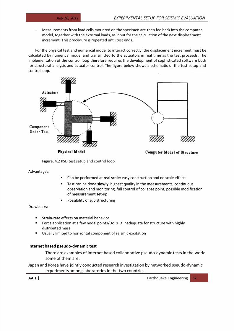
For the physical test and numerical model to interact correctly, the displacement increment must be
calculated by numerical model and transmitted to the actuators in real time as the test proceeds. The
implementation of the control loop therefore requires the development of sophisticated software both
for structural analysis and actuator control. The figure below shows a schematic of the test setup and
control loop.
Figure, 4.2 PSD test setup and control loop
Advantages:
Can be performed at real scale: easy construction and no scale effects
Test can be done slowly: highest quality in the measurements, continuous
observation and monitoring, full control of collapse point, possible modification
of measurement set-up
Possibility of sub structuring
Drawbacks:
Strain-rate effects on material behavior
Force application at a few nodal points/DoFs → inadequate for structure with highly
distributed mass
Usually limited to horizontal component of seismic excitation
Internet based pseudo-dynamic test
There are examples of internet based collaborative pseudo-dynamic tests in the world
some of them are:
Japan and Korea have jointly conducted research investigation by networked pseudo-dynamic
experiments among laboratories in the two countries.

8/17/2019 Experimental Setup for Seismic Evaluation.pdf
http://slidepdf.com/reader/full/experimental-setup-for-seismic-evaluationpdf 31/33
July 18, 2011 EXPERIMENTAL SETUP FOR SEISMIC EVALUATION
AAiT | Earthquake Engineering 33
The NEES (Network for Earthquake Engineering Simulation) project which has been launched by
the National Science Foundation of USA, aims at exploring the tremendous benefits of
sharing and integrating laboratory resources, including expensive equipments,
experiment data and simulation code via network.
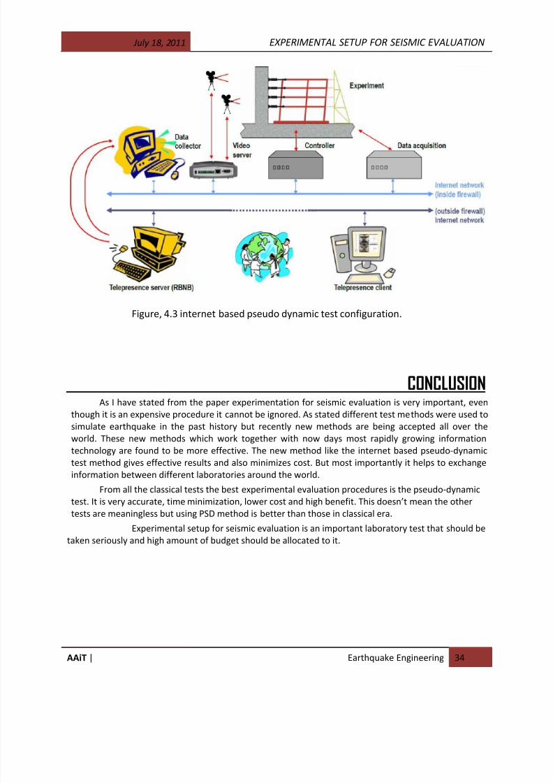
A prototype of an Internet based cooperative structural experimental environment, called ISEE
(internet- based simulations for earthquake Engineering), is constructed as the platform for a distributed pseudo-dynamic experiment. ISEE consists of three major parts:
The data center
The facility controller
The analysis engine
The details are introduced below.
The data center serves as a data exchange hub and repository in a collaborative experiment.
It is based on a database server, which allows exchanging experimental or analysis data among
the distributed laboratories. The data viewer allows researchers to setup their experimentalparameters through a www interface before the experiment starts. A data viewer is actually a
www browser, such as Microsoft internet explorer or Mozilla. Anyone on the internet can
access the experimental data through an internet without installing any additional software.
The cameras are set up in the laboratories to capture the video images of specimens during an
experiment, and the images are sent to a video server. The data center is linked to the video
server and shares the images via www server, so that the data viewer can witness the
experimental response and the video images in real time during the actual test.
The facility controller is the software bridge between the experimental facility in a
laboratory and the data center. In a typical pseudo-dynamic test, it receives the deformationdata from the data center and forwards them to the experimental facilities( servo hydraulic
actuator controller), then receives restoring force data and sends them back to the data center.
The analysis engine computes the dynamic responses of a structure by considering both the
finite element analytical responses and the experimental responses of the specimen. In a
distributed pseudo-dynamic test, the analysis engine performs a finite element dynamic
analysis, in which the resisting forces of one or more elements are obtained from the measured
forces from the laboratory. The analysis engine iteratively sends the target displacements to
the data center, to share with the facility controllers of the distributed laboratories or data
viewers.
8/17/2019 Experimental Setup for Seismic Evaluation.pdf
http://slidepdf.com/reader/full/experimental-setup-for-seismic-evaluationpdf 32/33
July 18, 2011 EXPERIMENTAL SETUP FOR SEISMIC EVALUATION
AAiT | Earthquake Engineering 34
Figure, 4.3 internet based pseudo dynamic test configuration.
CONCLUSIONAs I have stated from the paper experimentation for seismic evaluation is very important, even
though it is an expensive procedure it cannot be ignored. As stated different test methods were used tosimulate earthquake in the past history but recently new methods are being accepted all over the
world. These new methods which work together with now days most rapidly growing information
technology are found to be more effective. The new method like the internet based pseudo-dynamic
test method gives effective results and also minimizes cost. But most importantly it helps to exchange
information between different laboratories around the world.
From all the classical tests the best experimental evaluation procedures is the pseudo-dynamic
test. It is very accurate, time minimization, lower cost and high benefit. This doesn’t mean the other
tests are meaningless but using PSD method is better than those in classical era.
Experimental setup for seismic evaluation is an important laboratory test that should be
taken seriously and high amount of budget should be allocated to it.

8/17/2019 Experimental Setup for Seismic Evaluation.pdf
http://slidepdf.com/reader/full/experimental-setup-for-seismic-evaluationpdf 33/33
July 18, 2011 EXPERIMENTAL SETUP FOR SEISMIC EVALUATION
REFERENCE
1. Development of Remote Pseudo-Dynamic Test Method via Internet , Hyung Tae KIM,
Yong Doo KIM and Jae Kwan KIM, Division of Structural Engineering, Hyundai Institute of Construction
Technology. 2. Vibration and Shock Handbook, Clarence W. de Silva, TAYLOR &FRANCIS GROUP, 2005.
3. Seismic Engineering Research Infrastructures for European Synergies. SERIES,
commission of the European communities.
4. http//:www.series.upatrs.gr/course.JRC, web reference.