experimental study of active vibration suppression of flexible structure using modular control patc
TRANSCRIPT
Experimental Study of Active Vibration Suppression Structure Using Modular Control Patch*
Gangbing Song Steve P. Schmidt Brij. N. Agrawal
Spacecraft Research and Design Center Department of Aeronautics and Astronautics
U.S. Naval Postgraduate School Monterey, CA 93943
ABSTRACT - This paper presents experimental results of vibration suppressicln of a flexible structure using a miniaturized digital controller, called Modular Control Patch (MCP). The h4CP employs a TIC30 digital signal processor and was developed by TRW for the United States Air Force for future space vibration control. In this research, the MCP is used to implement different control algorithms for vibration suppression of a cantilevered aluminum beam with piezoceramic sensors and actuators. Positive Position Feedback (PPF) control, Strain Rate Feedback (SRF) control, and their combinations were implemented. Expenments found that PPF control is most effective for single- mode vibration suppression, and two PPF filters in parallel are most effective for multi-mode vibration suppression. Further experiments demonstrated the robustness of PPF control. PPF can achieve effective vibration suppression when there is a 20% error in modal frequency.
TAElLE OF CONTENT
1. INTRODUCTION
2. EXPERIMENTAL SETUP
3. MODULAR CONTROL PATCH
4. METHODS €OR VIBRATION SUPPRESSION
5. EXPERIMENTAL RESULTS OF SINGLE MODE vIBRAnora SUPPRESSION
6. EXPERIMENTS ON MULTI-MODE VIBRATION SUPPRESSION
7. CONCLUSIClN
All authors of this work are employees of US Govemment and performed this work as part of their official duty and this work is therefore not subject to US copyright protection.
of Flexible
1. INTRODUCTION
The current trend of spacecraft design is to use large, complex, and light weight space structures to achieve increased functionality at a reduced launch cost. The combination of large and light weight design results in these space structures being extremely flexible and having low fundamental vibration modes. Active vibration control has been increasingly used as a solution for spacecraft structures to achieve the degree of vibration suppression required for precision pointing accuracy. This paper examines the effectiveness and suitability of the Modular Control Patch (MCP) to implement various control algorithms to achieve active vibration control on flexible structures with embedded piezoceramic sensors and actuators.
The MCP is a miniaturized digital controller for future space applications in vibration suppression. The MCP was developed by TRW for the United States Air Force and uses a digital microprocessor to implement control algorithms. In this research, the MCP is used for vibration suppression of a cantilevered beam. The first two modes of the beam are found to be dominant. The cantilevered beam has piezoceramic sensors and piezoceramic actuators. Piezoceramics have several desirable characteristics for this type of application. These include high strain sensitivity, high stiffhess, low noise, good linearity, temperature insensitivity, ease of implementation, and low power consumption [l , 21.
Positive Position Feedback (PPF) control [3, 41 and Strain Rate Feedback (SRF) control [5] were designed and implemented using the MCP. These control laws were used independently and in combination in order to effectively suppress vibrations of the first two modal frequencies of the cantilevered beam. The PPF was found to be most effective for single mode vibration suppression. Two PPF filters in parallel provides the most effective multi-mode
189
Authorized licensed use limited to: Naval Postgraduate School. Downloaded on June 3, 2009 at 11:44 from IEEE Xplore. Restrictions apply.
damping. Further experiments tested the robustness of the PPF control. In the robustness analysis, the modal frequency used for control design is varied from 20% of the real value to 400% to study PPF's robustness to unknown modal frequency. Robustness of the PPF controllers for single-mode and multi-mode vibration suppression are studied. Experiments show that PPF is robust to variations of the modal frequency of the flexible structure. PPF can achieve effective vibration suppression when there is as much as 40% error in modal frequency. The robustness of a PPF controller can also be increased by using a larger compensator damping ratio.
2. EXPERIMENTAL SETUP
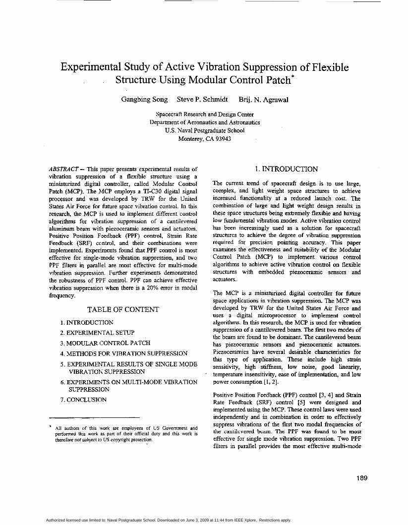
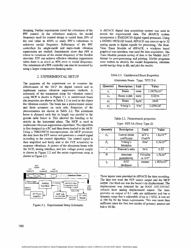
The purposes of the experiment are to examine the effectiveness of the MCP for digital control and to implement various vibration suppression methods. A schematic of the equipment setup for vibration control using MCP is shown in Figure 2.1. A cantilevered beam (its properties are shown in Table 2.1) is used as the object for vibration control. The beam has a piezoceramic sensor and three actuators on each side. Properties of the piezoceramics are shown in Table 2.2. The aluminum beam is clamped such that its length was parallel to the granite table below it. This allowed the bending to be strictly in the horizontal plane. The MCP is used to implement vibration suppression algorithms. The algorithm is f is t designed in a PC and then down-loaded to the MCP. Using a TMS320C30 microprocessor, the MCP processes the data from the PZT sensor and generates a control signal according to the control algorithm. The control signal is then amplified and lastly sent to the PZT actuator(s) to suppress vibrations. A picture of the aluminum beam with the MCP, analog interface, and low voltage power supply is shown in Figure 2.2 and the entire experiment setup is shown in Figure 2.3.
PZT Sensor
PZT PZT PZT Achvltor b'I Actnuor #2 Achvltm #3
"
PC with Dmito;Jd Matlab
MCP with Amplifier T K 3 0 DSP
Controller
Figure 2.1. Experimental Setup Schematic
A dSPACE digital data acquisition system was used to record the experimental data. The dSAPCE system incorporates a TMS320C40 digital signal processer. Using a DS2003 W A D board, dSPACE can convert up to 32 analog inputs to digital signals for processing. The Real- Time Trace Module of dSPACE, a windows based graphical user interface, was used for data acquisition. The Trace Module permits saving of data in the Matlab .MAT format for post-processing and plotting. Matlab programs were written to identify the modal frequencies, calculate modal energy drop in dB, and plot the results.
Table 2.1. Cantilevered Beam Properties
Aluminum Beam Type: 7075 T-6
Table 2.2. Piezoceramic properties
Type: PZT-SA (Navy Type 11)
Quantity Description Value
Three inputs were provided to dSPACE for data recording. The first two were the PZT sensor output and the MCP output. The third one was the beam's tip displacement. The displacement was detected by an NAiS ANL1651AC infrared laser analog displacement sensor. The laser provides an output of 0.1 volts per millimeter and has a dynamic range that is adjustable of up to 1 kHZ. It was set at 100 Hz for the beam experiments. This was more than sufficient since the fist two modes of primary interest are below 10 Hz.
190
Authorized licensed use limited to: Naval Postgraduate School. Downloaded on June 3, 2009 at 11:44 from IEEE Xplore. Restrictions apply.
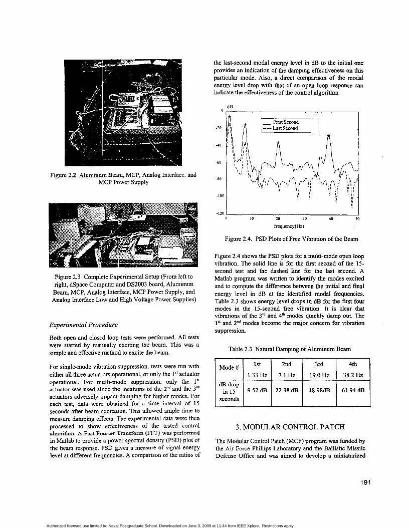
Figure 2.2 Aluminum Beam, MCP, Analog Interface, and MCP Power Supply
Figure 2.3 Complete Experimental Setup (From left to right, dSpace Computer and DS2003 board, Aluminum Beam, MCP, Analog Interface, MCP Power Supply, and Analog Interface Low and High Voltage Power Supplies)
Experimental Procedure
Both open and closed loop tests were performed. All tests were started by maiiually exciting the beam. This was a simple and effective method to excite the beam.
For single-mode vibration suppression, tests were run with either all three actualors operational, or only the 1" actuator operational. For multi-mode suppression, only the 1" actuator was used since the locations of the 2nd and the 3'' actuators adversely impact damping for higher modes. For each test, data wer'e obtained for a time interval of 15 seconds after beam excitation. This allowed ample time to measure damping effects. The experimental data were then processed to show effectiveness of the tested control algorithm. A Fast Fourier Transform (FFT) was performed in Matlab to provide a power spectral density (PSD) plot of the beam response. PSD gives a measure of signal energy level at different frequencies. A comparison of the ratios of
the last-second modal energy level in dB to the initial one provides an indication of the damping effectiveness on this particular mode. Also, a direct comparison of the modal energy level drop with that of an open loop response can indicate the effectiveness of the control algorithm.
dB I
-120 I 0 10 20 30 40 50
frequency(Hz)
Figure 2.4. PSD Plots of Free Vibration of the Beam
Figure 2.4 shows the PSD plots for a multi-mode open loop vibration. The solid line is for the first second of the 15- second test and the dashed line for the last second. A Matlab program was written to identify the modes excited and to compute the difference between the initial and final energy level in dB at the identified modal frequencies. Table 2.3 shows energy level drops in dE3 for the first four modes in the 15-second fiee vibration. It is clear that vibrations of the 3'd and 4h modes quickly damp out. The 1" and 2"d modes become the major concern for vibration suppression.
Table 2.3 Natural Damping of Aluminum Beam
1st 2nd 3rd 4th 1 1.33Hz 1 7.1 Hz 1 19.0Hz 1 38.2Hz 1 Mode # I seconds
3. MODULAR CONTROL PATCH
The Modular Control Patch (MCP) program was funded by the Air Force Phillips Laboratory and the Ballistic Missile Defense Office and was aimed to develop a miniaturized
191
Authorized licensed use limited to: Naval Postgraduate School. Downloaded on June 3, 2009 at 11:44 from IEEE Xplore. Restrictions apply.
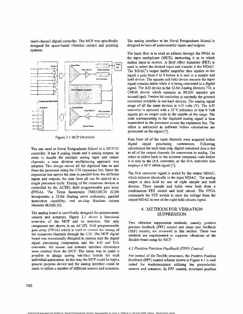
multi-channel dgital controller. The MCP was specifically designed for space-based vibration control and pointing systems.
d
a
ux
Gam MDAC
V I Digital Board -- Figure 3.1 MCP Overview
The one used at Naval Postgraduate School is a MCP-I11 controller. It has 8 analog inputs and 6 analog outputs. In order to handle the multiple analog input and output channels, a time division multiplexing approach was adopted. This design moves all the digitized data to and from the processor using the C30 expansion bus. Since the expansion bus moves the data in parallel from the different inputs and outputs, the data from all can be moved in a single processor cycle. Timing of the numerous devices is controlled by the ACTEL field programmable gate array (FPGA). The Texas Instrument TMS320C30 (C30) incorporates a 32-bit floating point arithmetic, parallel instruction capability, and on-chip Random Access Memory (RAM) [6] .
The analog board is specifically designed for piezoceramic sensors and actuators. Figure 2.1 shows a functional overview of the MCP and its interface. The only component not shown is an ACTEL field programmable gate array (FPGA) which is used to control the timing of the numerous channels through the C30. The MCP digital board was intentionally designed to contain only the digital signal processing components and the A/D and DIA converter. All sensor and actuator interface electronics were omitted from the MCP. The intent was to make it possible to design analog interface boards for each individual application. In this way the MCP could be kept a general purpose device and the analog interface could be made to utilize a number of different sensors and actuators.
The analog interface at the Naval Postgraduate School is designed to have all piezoceramic inputs and outputs.
The basic flow is to send an address through the FPGA to the input multiplexer (MUX), instructing it as to which analog input to receive. A field effect transistor (FET) is used to select the desired input and transfer it the MDAC. The MDAC’s output buffer amplifier then applies to the signal a gain from 0 to 9 before it is sent to a sample and hold device. The sample and hold device ensures the input signal remains stable while it is being converted to a digital signal. The A/D device is the 1Zbit Analog Devices 774, a CMOS device which operates at 80,000 samples per second (sps). Twelve bit resolution is currently the greatest resolution available in rad-hard devices. The analog signal range of all the input devices is +IO volts (V). The AID converter is operated with a 10 V reference so that 0 Volt signals get an output code in the middle of the range. The code corresponding to the digitized analog signal is then transmitted to the processor across the expansion bus. The offset is subtracted in software before calculations are performed on the signal [7].
Data from all of the input channels were acquired before digital signal processing commences. Following calculations for each time step, digital command data is fed to all of the output channels for conversion to analog. The offset is added back to the actuator command code before it is sent to the D/A converter, as the DIA converter also employs a 10 V offset signal [7].
The DIA converter signal is scaled by the output MDAC, which behaves identically to the input MDAC. The analog output is then held by one of eight sample and hold devices. These sample and holds were built from a combination FET switch and hold circuit. The FPGA commands the FET switch to steer the voltage from the output MDAC to one of the eight hold circuits signal.
4. METHODS FOR VIBRATION SUPPRESSION
Two vibration suppression methods, namely positive position feedback (PPF) control and strain rate feedback (SRF) control, are reviewed in this section. These two methods are implemented to suppress vibrations of the flexible beam using the MCP.
4. I Positive Position Feedback (PPF) Control
For control of the flexible structures, the Positive Position Feedback (PPF) control scheme shown in Figure 4.1 is well suited for implementation utilizing the piezoelectric sensors and actuators. In PPF control, structural position
192
Authorized licensed use limited to: Naval Postgraduate School. Downloaded on June 3, 2009 at 11:44 from IEEE Xplore. Restrictions apply.

information is fed to a compensator. The output of the compensator, magnified by a gain, is fed directly back to the structure. The equations describing PPF operation are given as .
where 5 is a coordinate describing displacement of the structure, is the damping ratio of the structure, w is the natural frequency of the structure, G is a feedback gain, q is the compensator coordinate, & is the compensator damping ratio, and w, is the frequency of the compensator.
Figure 4.1 Positive Position Feedback block diagram
Assuming a single degree-of-freedom vibration of the beam is in the form of
and the phase angle c) is given by
(4.5)
When the structure vibrates at a frequency much lower than the compensator natural frequency, the phase angle approaches zero. Substituting Eq.4.4 with $=O into Eq.4.1 results in
j f +2qw5 + ( w 2 -Gpw2)< = 0 (4.6)
This results in the stiffness term being decreased. When the compensator and the structure have the same natural frequency, the phase is 7d2. In this case, the structural equation is
6 + (2qw + G P w ) ~ + w2G = 0 (4.7)
This case shows an increase in the damping term. When the compensator frequency is greater than the structure, the phase angle approaches 7 ~ . This results in a structure equation of
C ~ + ~ ~ W ~ + ( W ~ + G ~ W ~ ) E , = O (4.8)
- 0 1 4 ,/ IC- Active Damping M I 4 i
_--e __ -- b o=oc 0 -
Figure 4.2 PPF Phase Angle Plot
This results in an increase in the stiffness term. A plot of the phase angle versus frequency is shown in Figure 4.2. As can be seen from the figure, to achieve maximum damping, w, should be closely matched to w. Also any structural natural mode below w, will experience increased flexibility.
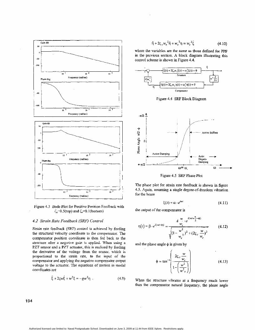
The effect of the damping ratio, t;, is discussed as follows. Larger values of the damping ratio, will result in a less steep slope thereby increasing the region of active damping. Figure 4.3 shows the bode plot for L4.5 and for t;=O.l. The difference in the slopes of the phase angle can easily be seen. A larger value of ensures a larger region of active damping and therefore will increase the robustness of the compensator with respect to uncertain modal frequencies. However, it is expected to result in slightly less effective damping and result in increased flexibility at lower modes as a trade-off. To study the impact of compensator damping ratio on compensator robustness and on possible increased flexibility at lower modes is one of the purposes for the experiments.
193
Authorized licensed use limited to: Naval Postgraduate School. Downloaded on June 3, 2009 at 11:44 from IEEE Xplore. Restrictions apply.
Gain dB 50 1
I I 10 I 10 2 I O
Frequency (radlsec) Phase deg
c I 10 1 10 10
Frequency ( r d s e c )
50 1
I I 10 ' 10 10 3
Frequency (radlsec) Phare deg
IO I 10 2 10 ' Frequency (radlsec)
Figure 4.3 Bode Plot for Positive Position Feedback with L=0.5(top) and k=O.l(bottom)
4.2 Strain Rate Feedback (SW) Control
Strain rate feedback (SRF) control is achieved by feeding the structural velocity coordinate to the compensator. The compensator position coordinate is then fed back to the structure after a negative gain is applied. When using a PZT sensor and a PZT actuator, this is realized by feeding the derivative of the voltage from the sensor, which is proportional to the strain rate, to the input of the compensator and applying the negative compensator output voltage to the actuator. The equations of motion in modal coordinates are
i j + 25 c ~ , 2 i + wC2q = wcZi (4.10)
where the variables are the same as those defied for PPF in the previous section. A block diagram illustrating this contxol scheme is shown in Figure 4.4.
i ( t ) + Zr,w,&t) + wi<(t) = 0
Compcnsator
Figure 4.4 SRF Block Diagram
Figure 4.5 SRF Phase Plot
The phase plot for strain rate feedback is shown in figure 4.5. Again, assuming a single degree-of-freedom vibration for the beam
c ( t ) = a .eiW' (4.1 1 )
the output of the compensator is
w i(wt+X-+)
wl- A - - . e 2
(4.12)
and the phase angle $ is given by
(4.13)
When the structure vibrates at a frequency much lower than the compensator natural frequency, the phase angle
194
Authorized licensed use limited to: Naval Postgraduate School. Downloaded on June 3, 2009 at 11:44 from IEEE Xplore. Restrictions apply.
approaches d2 . Substituting Eq.4.12 with +=O back into Eq.4.9 results in
+(2p+Gpw2)5 + w2t = 0 (4.14)
This results in an increase in the damping. When the compensator and the structure have the same natural frequency, the phase is 0". In this case, the structural equation is
5 + 2 p ~ 1 5 + ( w ~ +Gpw2)5 = O (4.15)
This case shows an increase in the stiffness term. When the compensator frequency is greater than the structure, the phase angle approaches ( 4 2 ) . This results in a structure equation of
e + (2qw - Gpw)( + w2k = 0 (4.16)
This results in a decrease in the damping term. Thus, in implementing SRF, lhe compensator should be designed so the targeted fkequencies are below the compensator frequencies.
Target Mode
1
1
2
2
SRF has a much wider active damping region which gives a designer some flexibility. Selecting a precise compensator frequency for SRF is not as critical as for PPF. As long as the compensator frequency is greater than the structural frequency, a certain amount of damping will be provided. A big limitation to SRF is that the magnitude of the transfer furiction in the active damping region becomes extremely small very quickly. Therefore, the amount of damping provided over a certain range is limited.
Parameters Modal dB %
fc=l .3 Hz, 44.20 dB 364%
Drop Change
&=0.5, gain = 4
fc=1.3 Hz, 61.89 dB 550% L=O.5, gain = 6
fc=7.1 Hz, 34.81 dB 55% L=0.5, gain = 2
&=0.5, gain = 6 fc=7.1 Hz, 44.00 dB 97%
5. EXPERIMENTAL RESULTS OF SINGLE MODE VII3RATION SUPPRESSION
5.1 PPF Experimlental Results
PPF control was implemented using the MCP to suppress the vibration of lst and 2nd modes, respectively. Experimental resultlj. of the PPF implementation are shown in Table 5.1. The last column shows the percent ratio of achieved modal energy drop in dB to that of the free vibration. Different gain values were tested. Table 5.1 shows higher gains achieved high vibration reduction. However, experiments found that larger gains were more likely to cause instalbility. The compensator damping ratio, C, was set to 0.5. This was chosen as a compromise between damping effectiveness and robustness.
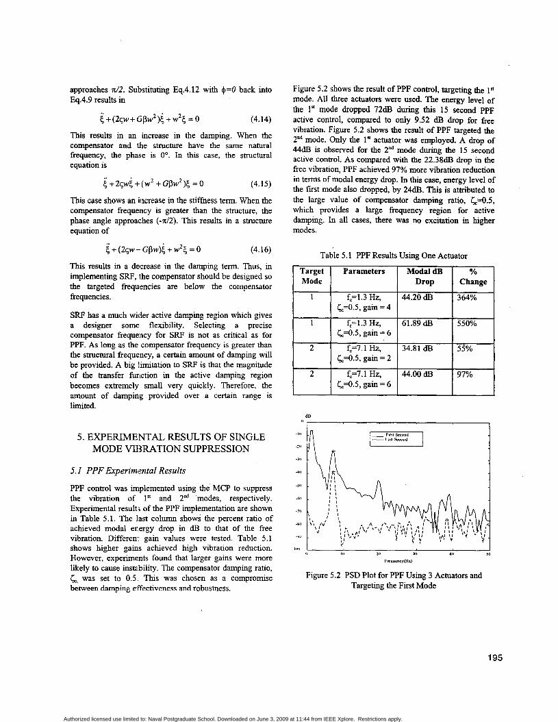
Figure 5.2 shows the result of PPF control, targeting the I* mode. All three actuators were used. The energy level of the 1' mode dropped 72dB during this 15 second PPF active control, compared to only 9.52 dB drop for free vibration. Figure 5.2 shows the result of PPF targeted the 2"d mode. Only the 1* actuator was employed. A drop of 44dB is observed for the 2"d mode during the 15 second active control. As compared with the 22.38dB drop in the free vibration, PPF achieved 97% more vibration reduction in terms of modal energy drop. In this case, energy level of the first mode also dropped, by 24dB. This is attributed to the large value of compensator damping ratio, &=OS, which provides a large frequency region for active damping. In all cases, there was no excitation in higher modes.
Table 5.1 PPF Results Using One Actuator
i 0 I II 20 30 40 50
FrrqurneyMz)
Figure 5.2 PSD Plot for PPF Using 3 Actuators and Targeting the First Mode
195
Authorized licensed use limited to: Naval Postgraduate School. Downloaded on June 3, 2009 at 11:44 from IEEE Xplore. Restrictions apply.
0
-20
-40
do
-80
-100
-120
dB
I
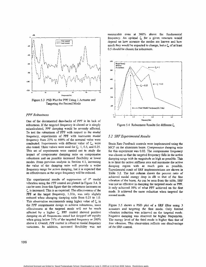
Figure 5.3 PSD Plot for PPF Using 1 Actuator and Targeting the Second Mode
measurable even at 300% above the fundamental frequency. An optimal & for a given structure would depend on how accurate the modes are known and how much they would be expected to change, but a r, of at least 0.5 should be chosen for robustness.
\
PPF Robustness
One of the documented drawbacks of PPF is its lack of robustness. If the targeted frequency is altered or is simply miscalculated, PPF damping would be severely affected. To test the robustness of PPF with respect to the modal frequency, experiments of PPF with inaccurate modal frequency from 25% to 400% of the nominal value were conducted. Experiments with different value of 6 , were also tested. Three values were used fork : 1, 0.5, and 0.25. This set of experiments were carried out to study the impact of compensator damping ratio on compensator robustness and on possible increased flexibility at lower modes. From previous analysis in Section 4.1, increasing the value of the damping ratio will provide a wider frequency range for active damping, but it is expected that its effectiveness at the target frequency will be reduced.
The experimental results of suppression of I" modal vibration using the PPF control are plotted in Figure 5.4. It can be seen from this figure that the robustness increases as r, is increased. This is as expected. The effectiveness of the PPF at the target frequency, 1.3Hz, was only slightly reduced when changing damping ratio from 0.25 to 1.0. This observation recommends using higher value of C, in the PPF compensator design to achieve robustness, since effectiveness at the targeted mode will not be much affected by a higher Cc. PPF control showed positive damping on all frequencies tested but dropped off rapidly when going below 75% of the targeted frequency or 200% above it. Overall, PPF control is robust to modal frequency variations. In addition, increased flexibility was not
I
0
~=cyo lz )
Figure 5.4 Robustness Results for different k
5.2 SRF Experimental Results
Strain Rate Feedback controls were implemented using the MCP on the aluminum beam. Compensator damping ratio for this experiment was 0.02. The compensator frequency was chosen so that the targeted frequency falls in the active damping range with its magnitude as high as possible. This is to limit the active stiffness area and maximize the active damping region with as much gain as possible. Experimental result of SRF implementations are shown in Table 5.2. The last column shows the percent ratio of achieved modal energy drop in dB to that of the free vibration of the beam. As can be seen from the table, SRF was not as effective in damping the targeted mode as PPF. It only achieved 50% of what PPF achieved on the first mode. It achieved the same reduction when targeted the second mode.
Figure 5.5 shows a PSD plot of a SRF filter using 3 actuators and targeting the first mode. Only limited vibration reduction was achieved on the targeted mode. Negative damping was observed for hlgher frequencies. The energy level of the third mode is higher than that of free vibration. This observation reflects one disadvantage of the SRF control.
196
Authorized licensed use limited to: Naval Postgraduate School. Downloaded on June 3, 2009 at 11:44 from IEEE Xplore. Restrictions apply.
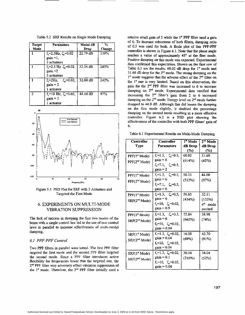
Table 5.2 SRF Results on Single Mode Damping
Target Mode
1
1
1
2
Parameters Modal dB YO
fc=2.5Hz, L=0.02 22.79 dB 139% gain = I , 3 actuators fc=2.5 Hz., &=0.02, 32.34 dl3 240% gain =2 3 actuators fc=2Hz, L4.02, 32.60 dI3 242% gain = 2 1 actuator fc=10 Hz, &=0.02, 44.10 dI3 97%
Drop Change
gain = 2
Controller Parameters
f1=1.3, &=OS, gain = 6 f ~ ~ 7 . 1 , L=0.5, gain = 2 f,=1.3, L=0.5, gain = 6 f2=7.1, L=0.5, gain = 6
dB
1" Mode dB Drop
68.02 (614%)
(%)
58.33 (513%)
0
f1=1.3, &=OS, gain = 6 f,=lO, &=0.02, gain = 0.9
I
50.85 (434%)
I 0 20 30 40 50 I O
Frrqucng(Hz)
-120 h
f1=1.3, &=0.5, gain = 6
gain = 0.04 f,=1.3, &=0.02, gain = 0.04
gain = 0.04 f1=1.3, &=0.02, gain = 0.1
gain = 0.04
f,=lO, &=0.02,
f*=IO, &=0.02,
f,=lO, L=0.02,
Figure 5.5 PSD Plot for SRF with 3 Actuators and Targeted the First Mode
72.84 (665%)
16.09 (69%)
30.04 (2 16%)
6 . EXPERIMENTS ON MULTI-MODE VIBRATION SUPPRESSION
The lack of success in damping the fust two modes of the beam with a single control law led to the use of two control laws in parallel to increase effectiveness of multi-modal damping.
6. I PPF-PPF Control
Two PPF filters in parallel were tested. The first PPF filter targeted the first mode and the second PPF filter targeted the second mode. Since a PPF filter introduces active flexibility for frequencies lower that the targeted one, the 2nd PPF filter may adversely effect vibqation suppression of the 1" mode. ThereFore, the 2nd PPF filter initially used a
relative small gain of 2 while the lS PPF filter used a gain of 6. To increase robustness of both filters, damping ratio of 0.5 was used for both. A Bode plot of this PPF-PPF controller is shown in Figure 6.1. Note that the phase angle reaches a value of approximately 45O at the first mode. Positive damping on this mode was expected. Experimental data confi ied this expectation. Shown on the first row of Table 6.1 are the results: 68.02 dF3 drop for lS mode and 3 1.68 dB drop for the 2"d mode. The strong damping on the 1" mode suggests that the adverse effect of the Td filter on the 1" one is very limited. Based on this observation, the gain for the 2nd PPF filter was increased to 6 to increase damping on 2nd mode. Experimental data verified that increasing the 2nd filter's gain from 2 to 6 increased damping on the 2nd mode. Energy level on 2nd mode further dropped to 44.0 dI3. Although this did lessen the damping on the first mode slightly, it doubled the percentage damping on the second mode resulting in a more effective controller. Figure 6.2 is a PSD plot showing the effectiveness of the controller with both PPF filters' gain of 6.
Table 6.1 Experimental Results on Multi-Mode Damping
Controller Type
PPF( 1" Mode) PPF(2nd Mode)
PPF( 1 Mode)
PPF(2nd Mode)
PPF( 1 " Mode) SRF(2"d Mode)
PPF( 1 " Mode)
SRF(2nd Mode)
SRF( 1'' Mode) SRF(2nd Mode)
SFW( 1" Mode) SRF(2"d Mode)
2Dd Mode dB Drop
31.68 (42%)
44.00 (97%)
52.11 (133%) 4"' mode excited 38.98 (74%)
42.70 (91%)
34.04 (52%)
197
Authorized licensed use limited to: Naval Postgraduate School. Downloaded on June 3, 2009 at 11:44 from IEEE Xplore. Restrictions apply.
-80 t IO I 10
Frequency (radkec) ~ Phasedeg
IO ' IO IO Frequency (radkec)
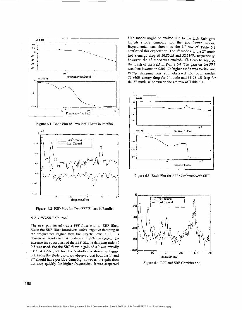
Figure 6.1 Bode Plot of Two PPF Filters in Parallel
dB 0
-20
-40
-60
-80
-100
-120
I
1 Y
J IO 20 30 40 50
frequency(&)
Figure 6.2 PSD Plot for Two PPF Filters in Parallel
6.2 PPF-SRF Control
The next pair tested was a PPF filter with an SRF filter. Since the SRF filter introduces active negative damping at the frequencies higher than the targeted one, a PPF is chosen to target the first mode and a SRF the second. To increase the robustness of the PPF filter, a damping ratio of 0.5 was used. For the SRF filter, a gain of 0.9 was initially used. A Bode plot for this controller is shown in Figure 6.3. From the Bode plots, we observed that both the 1" and Znd should have positive damping, however, the gain does not drop quickly for higher frequencies. It was suspected
high modes might be excited due to the high SRF gain though strong damping for the two lower modes. Experimental data shown on the 3"' row of Table 6.1 confirmed this expectation. The lSt mode and the 2nd mode had a energy drop of 50.85d.B and 52.11dB, respectively, however, the 4" mode was excited.. This can be seen on the graph of the PSD in Figure 6.4. The gain on the SRF was then lowered to 0.04. No higher mode was excited and strong damping was still observed for both modes: 72.84dl3 energy drop for 1" mode and 38.98 dE3 drop for the 2"d mode, as shown on the 4th row of Table 6.1.
"4 -100 i
-270 1- , , , 1 10 1 10 2
Frequency (rad/=)
Figure 6.3 Bode Plot for PPF Combined with SRF
-1 00 Ill 0 10 20 30 40 50
Frequency (Hz)
Figure 6.4 PPF and SRF Combination
198
Authorized licensed use limited to: Naval Postgraduate School. Downloaded on June 3, 2009 at 11:44 from IEEE Xplore. Restrictions apply.

6.3 SRF-SRF Control
The next combination tested was a controller using two SRF filters. Since the SRF filter introduces active negative damping at the frequencies higher than the targeted one, the la SRF filter will adversely effect the performance of the Yd SRF one. Therefore, SRF-SRF control is not expected very effective. Table 6.1 shows two cases of SRF-SRF control. A Bode plot for SRF-RSF control is shown in Figure 6.5. The gain was initially set at 0.04 for both filters. This produced effective damping on the second mode but very little on the first. For the Yd case, the gain was increased to 1 for the first filter to improve the damping on the 1" mode. First mode energy drop was increased from 16.09d.B to 3O.04dB7 but the increased gain also increased the active negative damping from the first filter and thus the second mode energy drop decreased from 42.7dB to 34.04idB. This can be seen on the PSD plot in Figure 6.6. As compared with the PPF-PPF control cases, the SRF-SRF control are not effective in damping out multi-mode vibrations.
Figure 6.5 Bode Plot for Two SRF Filters Combined
dB 0
-100 0 10 20 30 40 50
frequency(W
Figure 6.6 PSD Plot for Two SRF Filters Combined
6.4 Robustness Analysis of PPF-PPF Control
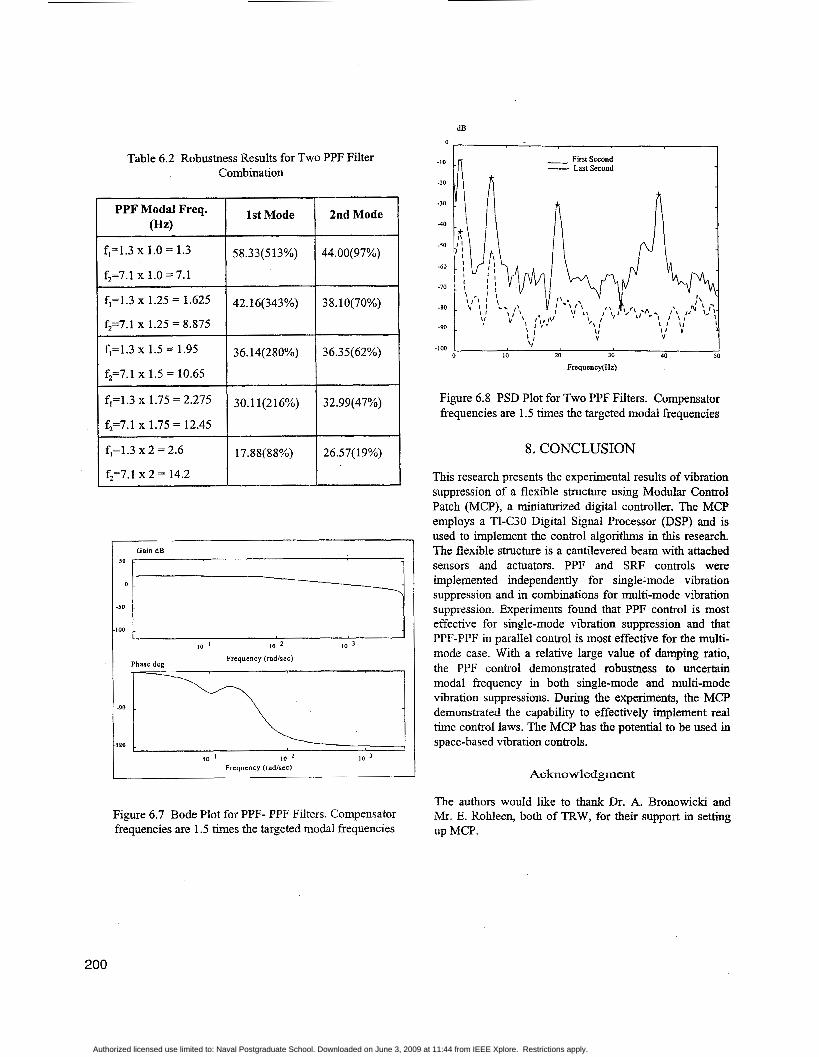
Given the effectiveness of PPF-PPF filters, tests were conducted to investigate the robustness of this type of controller. Table 6.2 shows the test results. A of 0.5 and a gain of 6 are used for both filters. Both compensator frequencies are moved progressively higher than the targeted natural frequency. As seen from the table, the first mode damping falls off much quicker than the second mode. Part of the reason for this is the increased stiffness region of the first filter is moving closer to the second mode thereby helping to increase the damping effect. Just as in the single PPF case, the PPF combination shows good robustness for both modes. These results suggest that along with being robust, the two PPF filter combination is effective in damping multiple modes over a range of frequencies. A Bode plot of the controller with both compensator frequencies set at 1.5 times the targeted modal frequencies is shown in Figure 6.7. A PSD plot for the same controller graphically illustrating damping effectiveness is shown in Figure 6.8.
199
Authorized licensed use limited to: Naval Postgraduate School. Downloaded on June 3, 2009 at 11:44 from IEEE Xplore. Restrictions apply.
dB 0
1
Table 6.2 Robustness Results for Two PPF Filter Combination
1 PPF M g ; Freq. 1 IstMode
fl=1.3 x 1.0 = 1.3
f2=7.1 x 1.0 = 7.1
5 8.3 3 (5 1 3%)
fl=1.3 x 1.25 = 1.625
f2=7.1 x 1.25 = 8.875
42.16(343%)
fl=1.3 X 1.5 = 1.95 36.14(280%)
f2=7.1 x 1.5 = 10.65
fl=1.3 X 1.75 =2.275 30.11(216%)
f2=7.1 x 1.75 = 12.45
fl=1.3 x 2 = 2.6
f2=7.1 x 2 = 14.2
17.88( 88%)
2nd Mode
44.00(97%)
38.10(70%)
26.57( 19%)
Gain dB 50 1
100 -50 t 10 ' 10 2 10 3
Frequency (radlrec) Phase deg
Frequcocy (radlscc)
Figure 6.7 Bode Plot for PPF- PPF Filters. Compensator frequencies are 1.5 times the targeted modal frequencies
-1w I I I 0 10 20 30 40 50
Frequency(Hz)
Figure 6.8 PSD Plot for Two PPF Filters. Compensator frequencies are 1.5 times the targeted modal frequencies
8. CONCLUSION
This research presents the experimental results of vibration suppression of a flexible structure using Modular Control Patch (MCP), a miniaturized digital controller. The MCP employs a TI-C30 Digital Signal Processor (DSP) and is used to implement the control algorithms in this research. The flexible structure is a cantilevered beam with attached sensors and actuators. PPF and SRF controls were implemented independently for single-mode vibration suppression and in combinations for multi-mode vibration suppression. Experiments found that PPF control is most effective for single-mode vibration suppression and that PPF-PPF in parallel control is most effective for the multi- mode case. With a relative large value of damping ratio, the PPF control demonstrated robustness to uncertain modal frequency in both single-mode and multi-mode vibration suppressions. During the experiments, the MCP demonstrated the capability to effectively implement real time control laws. The MCP has the potential to be used in space-based vibration controls.
Acknowledgment
The authors would like to thank Dr. A. Bronowicki and Mr. E. Rohleen, both of TRW, for their support in setting up MCP.
200
Authorized licensed use limited to: Naval Postgraduate School. Downloaded on June 3, 2009 at 11:44 from IEEE Xplore. Restrictions apply.

1.
2.
3.
4.
5.
6.
7.
REFERENCES
Won, C.C., Sulla, J.L., Sparks Jr, D.W., and Belvin, W.K., “Application of Piezoelectric Devices to Vibration Suppression,’’ Journal of Guidance, Control, and Dynamics, Vol. 17, No. 6, November-December,
Chaudhry Z. and Rogers, C., Actuators for Smart Structures, Fiber Optic Smart Structures, John Wiley & Sons, Inc., New York, 1995.
Fanson, J.L. and Caughey, T.K., “Positive Position Feedback Contrcil for Large Space Structure,” AIAA Journal, Vol. 28, No. 4, April, 1990, pp.717-724.
Agrawal, B. N., Bang, H., and Jones, E., “Application of Piezoelectric Actuators and Sensors in the Vibration Control of Flexible Spacecraft Structures,” Forty Third Congress of the International Astronautical Federation, Washington, D.C., September, 1992
Agrawal, B. N., and Bang, H., “Active Vibration Control of Flexible Space Structures by using Piezoelectric Sensors and Actuators, Proceedings for the 14* Biennial ASME Conference, Albuquerque, NM, September, 1993.
Texas Instrumerits, Inc., TMS32OC3x, User’s Guide, 1992.
Bronowicki, A. J. and Rohleen E., Modular Control Patch (MCP), Final Report, TRW Space and Electronics Group, Redondo Beach, CA.
1994, pp.1333-1338.
Dr. Gangbing Song is an Assistant Research Professor in the Department of Aeronautics and Astronautics (AA) at US Naval Postgraduate School (NPS) since 1996. Before joining AA, Dr. Song was a research associate in Mechanical Engineering Department at NPS for one year. Prior to NPS, Dr. Song studied for
Ph.D. in the department of Mechanical Engineering at Columbia Universiiy in the City of New York from 1991 to 1995. Dr. Song received his M.S. degree in 1991, also from Columbia University, and his B.S. degree in 1989 from Zhejing University, P.R.China. Dr. Song is a member of AIAA and ASME. His research interests include robust control, adaptive control, neural network and their applications in robotics, vibration control and smart
LCDR Schmidt has served 14 years in the U.S. Navy and is currently assigned as the F-14 Program Integrator at Northrop Grumman Corporation’s production facility in St Augustine FL.. He is responsible for supervising the manufacturing, production, and flight test and evaluation of completed aircraft.
LCDR Schmidt received his B.S. in Electrical Engineering from the University of Illinois in 1984. He earned his M.S. and Engineer’s Degree in Aeronautical and Astronautical Engineering from the Naval Postgraduate School in 1997. His thesis research focused on the vibration suppression of flexible spacecraft structures. LCDR Schmidt is a graduate of the U.S. Navy Fighter Weapons School, the U.S. Naval Test Pilot School, and is a member of the American Institute of Aeronautics and Astronautics.
Dr. Brij N. Agrawal is a Professor in the Department of Aeronautics and Astronautics and Director of the Spacecraft Research and Design Center. Professor Agrawal came to NPS in 1989 and has since initiated a new M.S. curriculum in Astronautical Engineering in addition to
establishing the Spacecraft Research and Design Center. He has also developed research programs in attitude control of flexible spacecraft, “Smart” structures, and space robotics. Prior to NPS he worked for Communications Satellite Corporation (COMSAT) and International Telecommunications Satellite Organization (INTELSAT) where he conducted research in spacecraft attitude dynamics, structural dynamics, and spacecraft testing. He has participated in the development of INTELSAT IV, IV- A, V, VI, and VII, COMSTAR, and MARISAT satellites. Professor Agrawal has written an industry recognized textbook “Design of Geosynchronous Spacecraft”, has over 40 technical papers, and has a patent for an attitude pointing error correction system for geosynchronous satellites. Professor Agrawal received his Ph.D. in Mechanical Engineering from Syracuse University in 1970 and his M.S. in Mechanical Engineering from McMaster University in 1968. He has received the NPS Outstanding Teacher Award, an AIAA Space Design Award, and the INTELSAT Award for Inventiveness and Technological Contribution. Professor Agrawal is an Associate Fellow of the American Institute of Aeronautics and Astronautics and a registered P.E. in the state of Maryland.
structures.
201
Authorized licensed use limited to: Naval Postgraduate School. Downloaded on June 3, 2009 at 11:44 from IEEE Xplore. Restrictions apply.