experimental study of blasting excavation for large cross
TRANSCRIPT

Experimental Study of Blasting Excavation for LargeCross-Section Tunnel in Horizontal Layered RockMassJie Mei
Geotechnical and Structural Engineering Research Center, Shandong UniversityWanzhi Zhang ( [email protected] )
School of Transportation and Civil Engineering, Shandong Jiaotong UniversityBangshu Xu
Geotechnical and Structural Engineering Research Center,Shandong UniversityYongxue Zhu
China Railway Tunnel Group No.2 Co LtdBingkun Wang
China Railway Tunnel Group No.2 Co Ltd
Original Paper
Keywords: large cross-section tunnel, horizontal layered rock mass, blasting excavation, �eld test,optimization of blasting parameters
Posted Date: February 9th, 2021
DOI: https://doi.org/10.21203/rs.3.rs-180296/v1
License: This work is licensed under a Creative Commons Attribution 4.0 International License. Read Full License
1
Experimental study of blasting excavation for large cross-section 1
tunnel in horizontal layered rock mass 2
Jie Mei 1, Wanzhi Zhang 2 , Bangshu Xu 1, Yongxue Zhu 3, Bingkun Wang 3 3
1 Geotechnical and Structural Engineering Research Center, Shandong University, Jinan 250061, China 4
2 School of Transportation and Civil Engineering, Shandong Jiaotong University, Jinan 250357, China 5
3 China Railway Tunnel Group No. 2 Co Ltd, Langfang 065201, China 6
* CORRESPONDENCE: Wanzhi Zhang; Email: [email protected] 7
Abstract The drilling and blasting method is still the main method in mountain tunnel excavation. For large cross-8
section tunnel in horizontal layered rock mass, tunnel blasting often causes serious overbreak and underbreak. In this 9
study, blasting excavation tests of tunnel upper face were conducted and failure mechanisms of surrounding rocks with 10
weak beddings and joints were analyzed based on the Panlongshan tunnel. Then, the blasthole pattern, the cut mode, a 11
variety of peripheral holes, the charge structure and the maximum single-hole charge were optimized. Compared with 12
the failure characteristics, overbreak and underbreak, and deformations of surrounding rocks before and after 13
optimization, the latter was better in tunnel contour forming and surrounding rock stability. The results show that after 14
optimization, the large-area separation of vault rock mass is solved, the step-like overbreak of spandrel rock mass is 15
reduced and the large-size rock blocks and underbreak are avoided. The maximum linear overbreak of vault, spandrel, 16
and haunch surrounding rocks is decreased by 42.3%, 53.7% and 45.1%, respectively. The underbreak at the bottom of 17
the upper face is reduced from -111.5 to - 16.5 cm. The average overbreak area is decreased by 61.1%. In addition, the 18
displacements after optimization finally converge to the smaller values. The arch crown settlement and the horizontal 19
convergence of haunch are reduced by about 21.6% and 18.3%, respectively. Furthermore, from the completion of 20
blasting excavation to the stabilization of surrounding rock, it takes less time by using the optimized blasting scheme. 21
Keywords large cross-section tunnel; horizontal layered rock mass; blasting excavation; field test; optimization of 22
blasting parameters 23
1. Introduction 24
In railway, highway and subway engineering, advanced controlled blasting techniques are the most 25
commonly used methods of tunnel excavation for rapid tunnelling (Adhikari et al. 1999; Fu et al. 2010; 26
Costamagna et al. 2018). Smooth blasting is the most commonly used method and a kind of controlled blasting 27
technique, which meets the design requirements of the smooth contour line by using fine blasting parameters and 28
division and subsection millisecond blasting (Sumiya and Kato 2007; Mandal et al. 2008; Johansson and 29
Ouchterlony 2013). For a smooth blasting design, the damage on surrounding rock is mainly influenced by the 30
geotechnical conditions (e.g. discontinuous beddings and joints, and rock properties) and blasting parameters such 31
as the blasthole pattern and the charge scheme (Ramulu et al. 2009; Johnson 2010). Since tunnel excavation in 32
horizontal layered rock mass is subjected to a large number of bedding planes, there is difficulty in forming a 33
smooth excavation line using smooth blasting. In fact, the propagation of explosion energy is greatly influenced 34
by the weak structural planes (e.g. barrier and leakage), leading to large overbreak or even collapse of surrounding 35
rock. Therefore, the influence of weak structural planes on the smooth blasting excavation are required to be 36
investigated systematically. Based on this, the protective blasting parameters to forming smooth tunnel contour 37
line need to be proposed urgently. 38
In a tunnel face, according to the sequence of firing charges, the blasting excavation is occurred layer by 39
layer from the center to the outside. First, the cut blasting occurs to break rock mass and throw broken stones to 40
create a new free surface. Then, the relief blasting is carried out step by step to form larger blasting cavity. Finally, 41

2
the smooth blasting is conducted to create a smooth contour line. To date, many researches related to fine blasthole 42
patterns and charge schemes for decreasing overbreak have been carried out. Shuifer and Azarkovich (1982) 43
proposed the maximum permissible linear mass of the contour charge through formula derivation. Hinzen (1998) 44
carried out a comparison between the measured seismic energy and the total explosive energy based on five smooth 45
production blasting tests and claimed that the explosive performance and electronic initiation system contributed 46
to the success of the smooth contour. Li et al. (2017) studied the smooth blasting fracture mechanisms from the 47
timing sequence control techniques. Taking into account the specified control indices, including the arch crown 48
settlement, thickness of the blasting damage zone, Liu and Liu (2017) put forward an intelligent optimization 49
method of smooth blasting parameters for mountain tunnels by using a GA and ISVR coupling algorithm. Salum 50
and Murthy (2019) suggested overbreak control methods by means of optimizing blasthole distance and the 51
thickness of smooth blasting rock layer, as well as the charge of peripheral hole. 52
Tunnel excavation in the horizontal layered rock mass is highly influenced by the complex weak structural 53
planes (Solak 2009; Deng et al. 2014). Some related studies indicate that under this geological structure, the 54
explosive stress wave will be blocked from the structural planes, causing damage to the remaining rock mass out 55
of excavation contour. Li and Ma (2009) employed an experimental technique to study the stress wave propagation 56
across jointed rock mass and found that the joint width has a significant effect on the dynamic behavior of rock 57
mass. Xie et al. (2016) developed the compression-shear damage model by considering damage patterns of rock 58
mass and presented that the superposition of stress wave and the reflected tension waves from free surfaces 59
contribute to the rock damage by using the finite element program. Deng et al. (2017) analyzed the mechanism of 60
horizontal bedding in the process of propagation of explosive stress wave and theoretically explained the causes 61
for overbreak on vault rock of tunnel. 62
Although there are many studies focused on the overbreak control for tunnels in jointed rock mass by proper 63
blasting parameters design. Unfortunately, as a result of the complexity of influencing factors of tunnel blasting 64
excavation and lack of understanding of the weak structural planes, there are no specific criterions and methods to 65
determining the fine blasting parameters. For the large cross-section tunnel in the horizontal layered rock mass, it 66
is necessary to study the practical blasting parameters in terms of the combined actions of horizontal beddings and 67
joints and failure mechanism of surrounding rock. In this study, the Panlongshan tunnel project of the Taian-68
Feicheng expressway in the Shandong province of China was taken as an engineering case. The damage 69
characteristics and overbreak of surrounding rock under the original blasting scheme (without taking into account 70
the impact of bedding and joints) are first collected. Then, the mechanism analysis of weak structural planes on 71
smooth blasting results was conducted and the causes of the severe overbreak are discussed systematically. Finally, 72
the optimized controlled blasting parameters for tunnel excavation are proposed, and the applicability is proved 73
by the next field blasting tests. 74
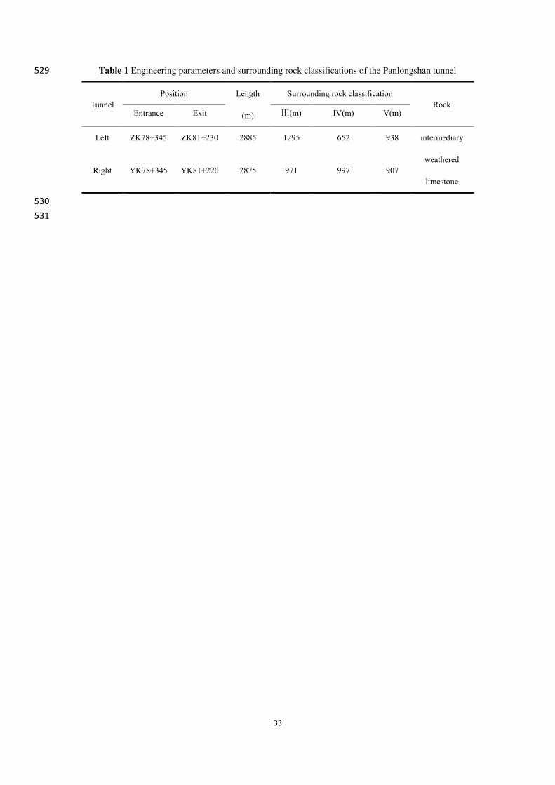
2. Panlongshan tunnel project 75
2.1 Engineering background and excavation method 76
The Panlongshan tunnel is a two-way separation-type tunnel located in the Taian-Feicheng expressway in 77
the Shandong province of China. The lengths of the left and right tunnels are 2885 and 2875 m, respectively. The 78
maximum cover depth of the tunnel is 160 m. Details of the tunnel engineering parameters and surrounding rock 79
classifications are listed in Table 1. The surrounding rock of the tunnel is dolomitic intermediary weathered 80
limestone with horizontal layered structure. The strike direction of the beddings is approximately parallel to the 81

3
axial direction of the tunnel. The geological longitudinal section along the tunnel axis is shown in Fig. 1. 82
Remarkably, joints and fissures are also developed in the rock mass, which are filled with mud. 83
As shown in Fig. 2, the width and height of the standard cross-section of Class-IV surrounding rock are 17.56 84
and 12.44 m, respectively. 85
[Table 1 near here] 86
[Figure 1 near here] 87
[Figure 2 near here] 88
Bench excavation method is used in the Class-IV surrounding rock. According to the field investigation and 89
monitoring measurement, overbreak and underbreak often occurs in the upper face due to the large excavation section 90
(see Fig. 3). Therefore, the blasting excavation tests are carried out on the upper face. The excavation width, height, 91
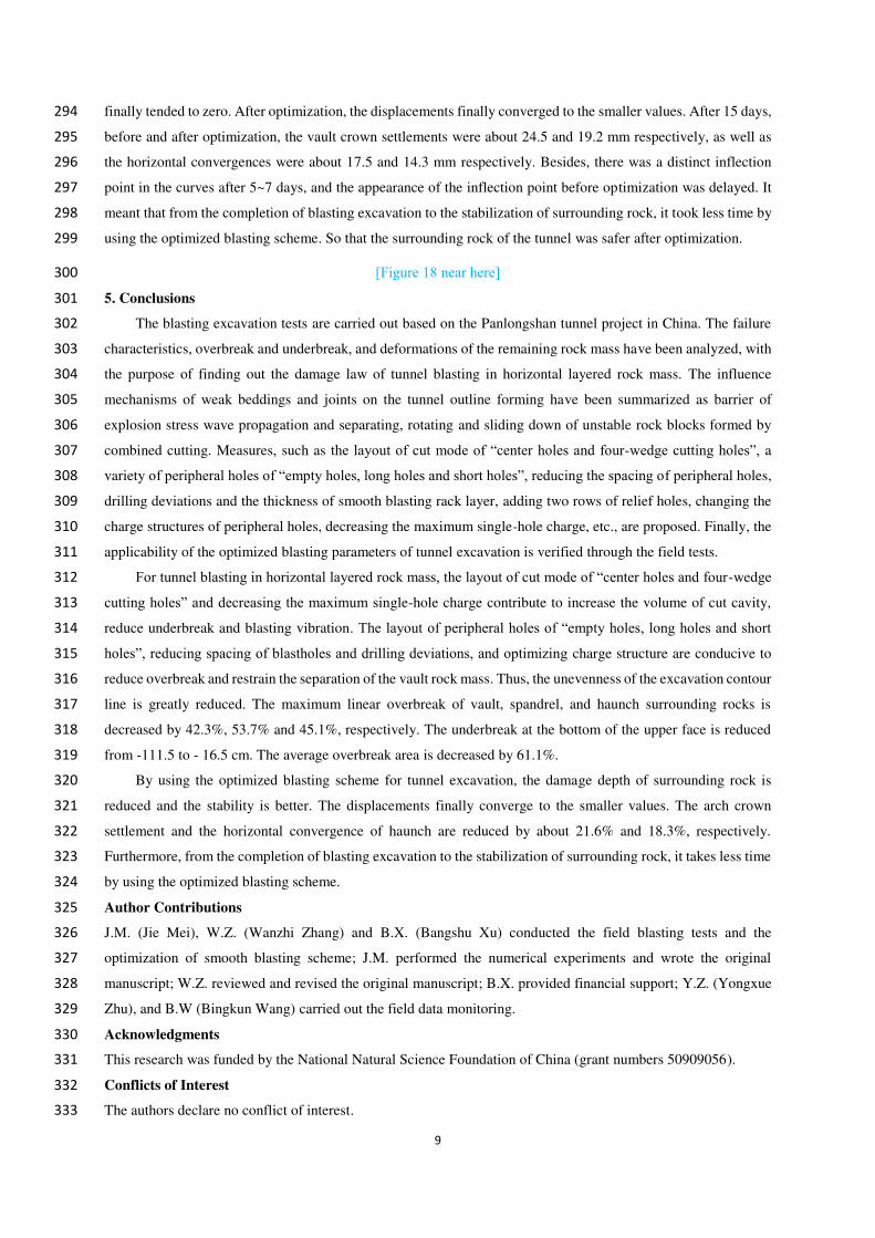
and area of the upper face are about 17.0 m, 7.5 m, and 101.3 m2, respectively. 92
[Figure 3 near here] 93
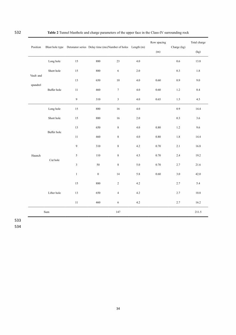
2.2 Blasting scheme of the upper face 94
2.2.1 Blasthole pattern 95
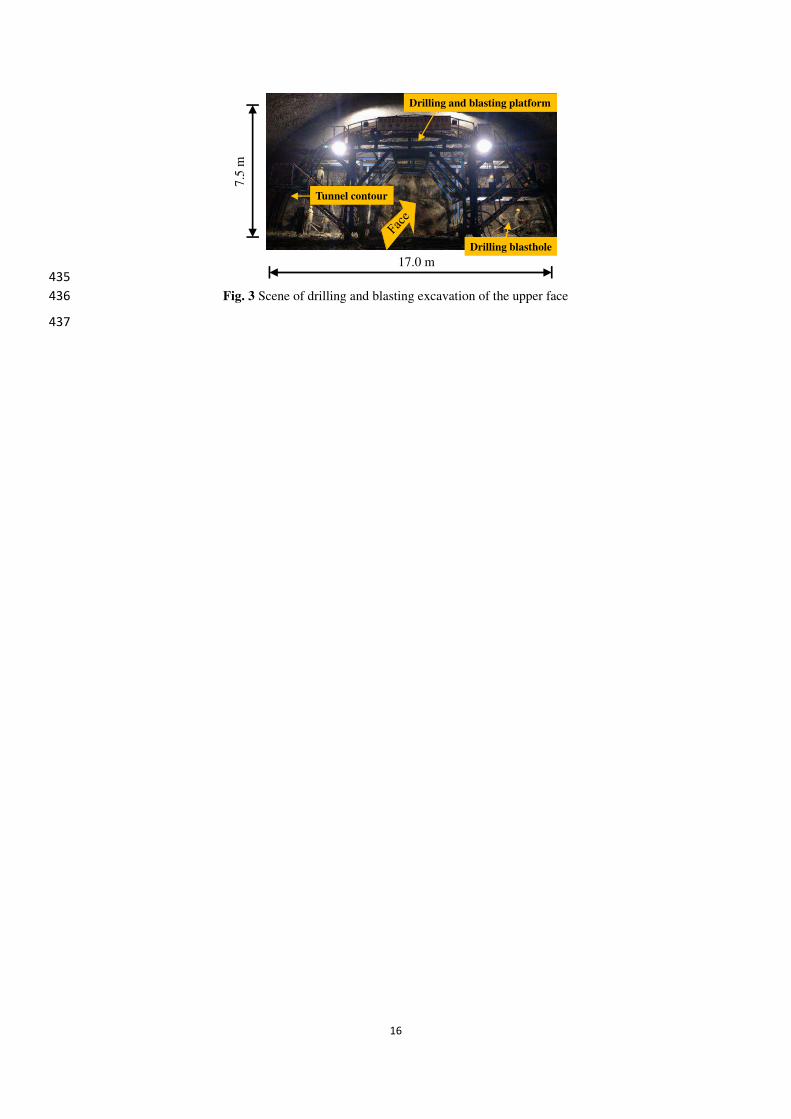
As shown in Fig. 3, the face is divided into three sub-sections based on the structure of the drilling and 96
blasting platform. As shown in Fig. 4(a), the sections A, B and C are the areas of wedge cutting blasting, relief 97
blasting and smooth blasting, respectively. The timing sequence of the blasting is from A to B to C. Fig. 4(b) 98
presents the design of the blasthole pattern and its parameters. The diameter of the holes is 42 mm, the length of 99
each round excavation is about 4.0 m and the electronic detonator series are from 1 to 15. Since the width of the 100
cutting blasting is about 8 m, in order to form an ideal cavity, the four-wedge cutting design is adopted. The spacing 101
of one-wedge cut holes is 0.6 m and that of the two-, three- and four-wedge cut holes is around 0.9 m. The lengths 102
and angles of these cut holes are 5.8, 5.0, 4.5 and 4.2 m, and 47°, 55°, 64° and 73°, respectively. 103
Due to the large free surface, the spacing of peripheral holes is 0.65 m at the vault and spandrel. In order to 104
effectively release the constraint of remained rock mass, the spacing of peripheral holes is 0.55 m at the haunch. 105
The thicknesses of smooth blasting rock layers are about 0.7 m at the vault and spandrel, and 0.8 m at the haunch. 106
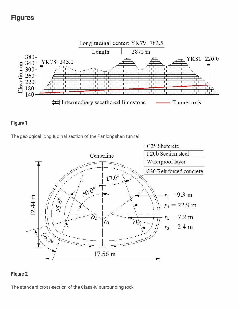
In addition, in order to weaken the influence of horizontal beddings, the interval layout of long holes and short 107
holes of peripheral holes is used. Fig.5. shows the design parameters of the long hole and short hole. The distances 108
of the long hole and short hole move inward from the contour is 20 and 14 cm, respectively. The lengths and look-109
out angles of the long hole and short hole are 4.0 and 2.0 m, and 5°and 8°, respectively. 110
Along the direction of the contour, the relief holes are distributed between the cut holes and peripheral holes 111
and are drilled in a staggered manner. The spacing of the relief holes are 1.0~1.5 m at the vault and spandrel, and 112
0.8~0.9 m at the haunch. 113
The bottom holes are located at the interface between the upper and lower faces with a distance about 1.3 m. 114
[Figure 4 near here] 115
[Figure 5 near here] 116
2.2.2 Charge and blasting network 117
The emulsion explosive with a diameter of 32 mm and a length of 0.3 m is used. The explosive density is 118
1125 kg/m3 and the velocity of detonation is 3200 m/s. The uncoupled charge with an uncoupled coefficient of 119
4
1.31 is used in the transverse direction, whereas in the longitudinal direction, the concentrated charge at the bottom 120
of blasthole is adopted. 121
A typical millisecond-delay blasting sequence is used. The cut holes are firstly detonated, followed by the 122
relief holes and the peripheral holes with delay intervals of 50 ~ 100 ms. The delay time is controlled by electronic 123
detonators in odd series (see Fig. 3). The blastholes in the vault are divided into left, middle and right parts, and 124
each part is clustered and detonated by detonators. The blastholes in the haunch is divided into left and right parts, 125
and each part is clustered and detonated by detonators. 126
To sum up, the parameters of blastholes and charges of upper face are listed in Table 2. 127
[Table 2 near here] 128
2.3 Results of blasting excavation 129
2.3.1 Failure characteristics of surrounding rock 130
From ZK80+263.0 to ZK80+239.6, the left tunnel was excavated 6 times by using the above blasting scheme. 131
The failure characteristics of surrounding rock after blasting excavation are shown in Fig. 6. It can be seen from 132
the arch remaining rock mass (Fig.6a, b, c), discontinuous horizontal beddings and vertical joints are developed. 133
The bedding spacing ranges from a few centimeters to tens of centimeters. These joints are intersected with 134
horizontal beddings, and the joints are filled with mud. Affected by the influence of horizontal beddings and joints, 135
the surrounding rock was badly damaged and the tunnel contour was very irregular. The vault rock mass fell off 136
along a bedding plane, forming a flat outline. At the spandrel, broken rocks slid down along a joint plane, leading 137
to a distinct step-like outline. The maximum height and width of step-like rock fracture surface were 72 and 34 138
cm. 139
It could be seen from the bottom remaining rock mass (Fig.6d, e), the face was roughness and there was 140
underbreak at the bottom. Because the distance of the one-wedge cut holes on the face was about 8.0 m, the cutting 141
blasting generated large-size stone. The length, width, and height of the stone was about 1.8 m × 1.0 m × 1.4 m. 142
In order to realize the transportation of large-size stone, it was necessary to carry out secondary drilling and 143
blasting. 144
[Figure 6 near here] 145
2.3.2 Overbreak and underbreak 146
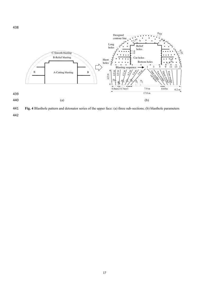
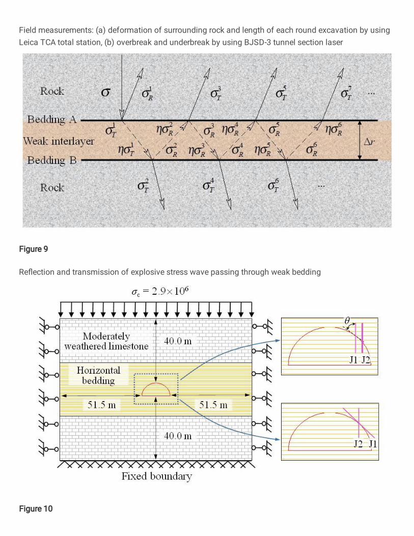
The Leica TCA total station and the BJSD-3 tunnel section laser were used to measure the length of each 147
round excavation, deformation of surrounding rock, overbreak and underbreak, as shown in Fig. 7. 148
The quantitative sizes of overbreak and underbreak of the test sections ZK80+254.2 and ZK80+250.4 are 149
shown in Fig. 8. It could be seen that the overbreak of the tunnel vault and spandrel after blasting excavation was 150
serious, and there was local underbreak at the middle and bottom of the upper face. The maximum linear overbreak 151
of the vault, spandrel and haunch were 39.0, 82.5 and 33.1 cm. The average overbreak area was 8.55 m2. The 152
maximum linear underbreak of the bottom was -111.5 cm. According to JTG F60-2009 (China First Highway 153
Engineering Company Ltd 2009) standard, the permissible overbreak of the tunnel vault and side wall are 250 and 154
100 mm, and underbreak is not allowed in tunnel excavation. Therefore, overbreak of the vault, spandrel and 155
haunch exceeded the standard value by 56.0%, 230.0% and 32.4%, respectively. 156
The average length of each round excavation was 3.65 m. An average blasting efficiency of 91.3 % had been 157
achieved. 158
5
[Figure 7 near here] 159
[Figure 8 near here] 160
2.4 Analysis of tunnel contour forming mechanism of horizontal layered rock mass 161
2.4.1 Barrier effect of beddings on stress wave propagation 162
When explosive stress wave passes through bedding or joint with a thickness of Δr, the reflection and 163
transmission are illustrated in Fig. 9. It is assumed that the stress wave σ is incident from the interface A, then 164
forms reflected wave σR1 and transmitted wave σT1 there. The transmitted wave σT1 is repeatedly reflected and 165
transmitted between interfaces A and B. A series of reflected waves σR and transmitted waves σT are formed, which 166
are expressed as: 167
1
12T T , 1
12R R ; 168
2 1
21T T T , 2 1
21R R T ; 169
3 2
21T T R , 3 2
21R R R ; 170
…… 171
1
21( 1)n n n
T T R , 1 1
21( 1)n n n
R R R (1) 172
where C1 and C2 are the P-wave velocity of rock and bedding; ρ is the density; therefore, (ρ0C)1 and (ρ0C)2 indicate 173
the wave impedance of rock and bedding, respectively; η is the attenuation coefficient of the stress wave as 174
propagating through the bedding. The parameters φT12 and φR12 are the transmission and reflection coefficients as 175
the wave entering from rock to bedding, while φT21 and φR21 are the transmission and reflection coefficients of the 176
reverse incidence, which can be expressed as: 177
0 2
12
0 1 0 2
2( )
( ) ( )T
C
C C, 0 2 0 1
12
0 1 0 2
( ) ( )
( ) ( )R
C C
C C; 178
0 1
21
0 1 0 2
2( )
( ) ( )T
C
C C, 0 1 0 2
21
0 1 0 2
( ) ( )
( ) ( )R
C C
C C (2) 179
The sum of the stress waves entering rock at interfaces A and B can be expressed as: 180
1 3 5 , 1,3,5n
A R T T Tn 181
2 4 6 , 2,4,6n
B T T T Tn (3) 182
The general expressions can be obtained by substituting Eqs. 1 and 2 into Eq. 3: 183
0 2 0 1
0 1 0 2
0 1 0 2 0 1 0 2
0 1 0 2 0 1 0 2 0 1 0 2
2 20 1 0 2
2 0 1 0 2
( ) ( )
( ) ( )
2( ) 2( ) ( ) ( )
( ) ( ) ( ) ( ) ( ) ( )
( ) ( )( 1) ( ) ,
( ) ( )
0,1,2 ; 3,5,7 ; 2 3
A
nm m
i
C C
C C
C C C C
C C C C C C
C C
C C
m n n m
(4) 184

6
0 1 0 2
0 1 0 2 0 1 0 2
20 1 0 2
4 0 1 0 2
2( ) 2( )
( ) ( ) ( ) ( )
( ) ( )1 ( 1) ( ) ,
( ) ( )
1,2,3 ; 4,6,8 ; 2 2
B
nm m
i
C C
C C C C
C C
C C
m n n m
(5) 185
According to Eqs. 4 and 5, the greater the difference of wave impedances between rock and bedding and the 186
smaller the thickness of bedding, the stronger the barrier effect on the explosive stress wave. As reported by Peng 187
(2018), if the stress wave was reflected and transmitted once within a bedding and the wave impedance ratio was 188
(ρ0C)1/(ρ0C)2 = 0.1, only 33.1% of the stress wave passed through the bedding. The bedding spacing of surrounding 189
rock in the test sections of the Panlongshan tunnel ranges from a few centimeters to tens of centimeters. Therefore, 190
there are some weak beddings between two peripheral holes. Besides, the mud within the weak interlayer further 191
strengthens the barrier effect on the explosive stress waves. As a result, more explosive energy propagates along 192
the weak beddings, leading to the blasting fractures, and eventually resulting in severe overbreak. 193
[Figure 9 near here] 194
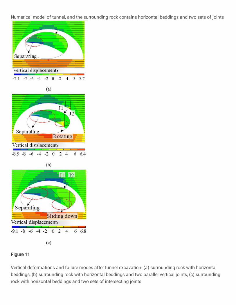
2.4.2 Separating, rotating and sliding down of unstable rock blocks 195
Affected by the cross cutting of beddings and joints and tunnel contour line, unstable rock blocks are formed 196
in the arch of tunnel after excavation(Wu and Chen 2001; Zhang et al. 2012). In our previous work, the failure 197
modes of the unstable rock blocks formed by the intersection of horizontal beddings and one or two sets of joints 198
and the tunnel contour line were studied in detail by using the ubiquitous joint model embedded in FLAC3D 199
(Zhang et al. 2020). Fig.10 shows the numerical model of tunnel. The surrounding rock contains horizontal 200
beddings and two sets of joints (J1 and J2). Based on the geological exploration data and geotechnical tests, normal 201
stiffnesses of 2.0 × 10⁹ Pa/m and 1.1 × 10⁹ Pa/m and shear stiffnesses of 0.8 × 10⁹ Pa/m and 0.5 × 10⁹ Pa/m were 202
used to represent deformability of the beddings and joints, respectively. Fig. 11 shows the deformation and failure 203
characteristics of the unstable rock blocks after the tunnel excavation. It could be seen from Fig. 11(a) that the 204
unstable rock blocks at the vault separated along a horizontal bedding plane under pressures of vault rock load and 205
rock gravity after excavation, causing overbreak. It could be seen from Fig. 11(b) that under the cross cutting of 206
horizontal beddings and two sets of vertical joints, one side of the free face of the unstable rock blocks separated 207
along a horizontal bedding plane, and the other side slid upward along a joint plane. Finally, the unstable rock 208
blocks rotated and fell down, resulting in overbreak. It could be seen from Fig. 11(c) that under the cross cutting 209
of horizontal beddings and two sets of intersecting joints, the unstable rock blocks either separated along a 210
horizontal bedding plane, or slid down along a joint plane, leading to overbreak. 211
[Figure 10 near here] 212
[Figure 11 near here] 213
3. Optimization of blasting scheme 214
3.1 Optimization of blasthole pattern 215
Fig. 12 shows the optimized blasthole pattern and its parameters. In order to enlarge the cut cavity, prevent 216
the underbreak at the bottom of the upper face, and avoid large-size stone produced by cutting blasting, the cutting 217
design is changed to the layout of center holes and four-wedge cutting holes. The spacing of center holes and the 218

7
distance from the bottom boundary are 1.0 m. The spacing of one-wedge cut holes is 0.6 m and that of the two-, 219
three- and four-wedge cut holes is around 0.9 m. The lengths and angles of these cut holes are 5.7, 4.9, 4.4 and 4.1 220
m, and 48°, 57°, 66° and 77°, respectively. 221
Given the barrier effect of weak structural planes on blasting load and the cross cutting of beddings and joints 222
and the tunnel contour line, a variety of peripheral holes with empty holes, long holes and short holes are designed 223
and drilled. According to the research (Li et al. 2018), total reflection occurs when the stress wave propagates to 224
the surface of the empty hole due to the wave impedance ratio of rock to air is close to zero. The reflected wave is 225
conducive to the tensile failure of the rock mass, resulting in the generation of blasting fractures. So the empty 226
holes are added at the spandrel and their spacing is 0.6 m. In addition, according to the JTG F60-2009 standard 227
and the research results (Singh and Xavier 2005; Dey and Murthy 2011; Xu et al. 2019), from soft to medium hard 228
rock, the spacing of peripheral holes ranges from 0.3 to 0.6 m. Thus, the spacing of long holes and short holes was 229
adjusted to 0.6 m. It’s remarkable that due to the interval drilling of empty holes, long holes and short holes, the 230
spacing of peripheral holes at the spandrel and haunch is determined as 0.3 m. 231
Fig. 13 presents the layout parameters of the optimized long hole and short hole. In order to decrease 232
excessive rock damage caused by drilling, the look-out angles of the long hole and short hole are set to 3° and 5°, 233
respectively. In addition, the distances of the long hole and short hole move inward from the contour is 15 and 12 234
cm, respectively. Therefore, the look-out distances from the bottom of the hole outside the contour line are 235
decreased to 6 and 5 cm, respectively. 236
Furthermore, from the haunch to the bottom, due to the large excavation width, four relief holes are added, 237
which are two rows, and are arranged symmetrically on the left and right sides. The horizontal spacing of relief 238
holes is reduced from 0.8 to 0.7 m. At the tunnel vault and spandrel, the spacing of relief holes are adjusted to 239
1.0~1.3 m. 240
[Figure 12 near here] 241
[Figure 13 near here] 242
3.2 Optimization of charge and charge structure 243
First, in order to reduce the vibration of cut blasting, the maximum single-hole charge of cut hole is 244
determined as the following formula: 245
cc
c
q l Sq
N (6) 246
where q represents explosive unit consumption, kg/m3; l is the length of blasthole; Sc represents section area of cut 247
cavity; Nc is the number of cut holes. Sc is expressed as 248
( )
2c
L D dS (7) 249
where L is the length of one side of the cutting cavity, m; D is the maximum spacing of cutting holes, m; d is the 250
spacing between the bottom of cut holes. 251
As shown in Fig. 12, L = 0.6×3, D = 7.8, d = 0.4, l = (4.1×8 + 4.4×8 + 4.9×8 + 5.7×16) / 40 = 4.96 and Nc = 252
40, we can obtain Sc = 7.38 m2. Since the test sections are the Class-IV surrounding rock, the Protodyakonov 253
coefficient f = 6, according to empirical statistics, q = 3.0 kg/m3. Based on the Eq.(6), qc = 2.7 kg. 254
8
Second, according to the Salum and Murthy’s research (Salum and Murthy 2019), the charge of peripheral 255
holes is obtained as follows: 256
0.57ln 0.26y x (8) 257
Where y represents charge of single peripheral hole, kg; x is the length of each round excavation, m. As shown in 258
Fig 14, when x = 4.0 m, y ≈ 1.0 kg. 259
[Figure 14 near here] 260
Third, the eccentric uncouple charge along the transverse direction and the air-deck charge along the 261
longitudinal direction are adopted. Fig. 15 presents charge structures of peripheral holes at different positions. The 262
emulsion explosives are divided into two segments of 0.2 and 0.1 m in length and placed separately in the holes. 263
The detonating cord goes through the entire length of the holes. The opening of the holes was blocked with a length 264
of 250 mm stemming. 265
Finally, the optimized parameters of blastholes and charges of upper face are given in Table 3. 266
[Figure 15 near here] 267
4. Result analysis and discussion 268
4.1 Failure characteristics of surrounding rock 269
From ZK80+235.7 to ZK80+216.7, the left tunnel was excavated 5 times by using the optimized blasting 270
scheme. Fig. 16 presents the failure characteristics of surrounding rock after blasting excavation. It could be 271
observed from Fig.16a, b, c, the unevenness of the excavated contour was significantly reduced compared with 272
the results in Fig.6a, b, c. At the vault, the excavated contour was curved rather than flat. There was no large area 273
of rock mass separation, only a few small-size broken rock blocks fell off. From spandrel to haunch, the excavated 274
contour was jagged instead of the step-like shape. There was no massive unstable rock blocks sliding down. It 275
could be seen from Fig.16d, e, the face was smooth, the bottom was flat and the sizes of the crushed stones were 276
small. The length, width, and height of the largest stone was about 0.8 m × 0.5 m × 0.4 m. The above excavation 277
results indicated that the optimized blasthole pattern and charge were practical. 278
[Figure 16 near here] 279
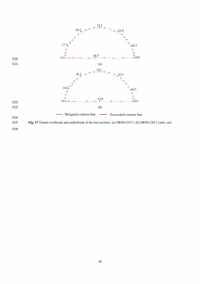
4.2 Overbreak and underbreak 280
The quantitative sizes of overbreak and underbreak of the test sections ZK80+235.7 and ZK80+220.1 are 281
illustrated in Fig. 17. The excavated contour of the tunnel was in good agreement with the designed contour. The 282
maximum linear overbreak at the vault, spandrel, and haunch was 22.5, 38.2, and 17.3 cm, respectively. The above 283
results were decreased by 42.3%, 53.7% and 45.1% compared with the values in Fig. 8. The average overbreak 284
area was 5.12 m2, which was decreased by 61.1%. The underbreak at the bottom of the upper face was reduced to 285
- 16.5 cm. The advantage was that the bottom was flat, which was conducive to the next tunnelling. 286
The average length of each round excavation was 3.76 m. An average blasting efficiency was 94.0%, which 287
was increased by 2.7% through a comparison with the previous result. 288
[Figure 17 near here] 289
4.3 Surrounding rock deformation 290
During the process of blasting excavation, the cumulative displacements of surrounding rock of the vault and 291
haunch before and after optimization are shown in Fig. 18. The displacement measurement was started right after 292
the shotcrete. The results for 17 days shown that the growth rate of the displacements decreased continually and 293
9
finally tended to zero. After optimization, the displacements finally converged to the smaller values. After 15 days, 294
before and after optimization, the vault crown settlements were about 24.5 and 19.2 mm respectively, as well as 295
the horizontal convergences were about 17.5 and 14.3 mm respectively. Besides, there was a distinct inflection 296
point in the curves after 5~7 days, and the appearance of the inflection point before optimization was delayed. It 297
meant that from the completion of blasting excavation to the stabilization of surrounding rock, it took less time by 298
using the optimized blasting scheme. So that the surrounding rock of the tunnel was safer after optimization. 299
[Figure 18 near here] 300
5. Conclusions 301
The blasting excavation tests are carried out based on the Panlongshan tunnel project in China. The failure 302
characteristics, overbreak and underbreak, and deformations of the remaining rock mass have been analyzed, with 303
the purpose of finding out the damage law of tunnel blasting in horizontal layered rock mass. The influence 304
mechanisms of weak beddings and joints on the tunnel outline forming have been summarized as barrier of 305
explosion stress wave propagation and separating, rotating and sliding down of unstable rock blocks formed by 306
combined cutting. Measures, such as the layout of cut mode of “center holes and four-wedge cutting holes”, a 307
variety of peripheral holes of “empty holes, long holes and short holes”, reducing the spacing of peripheral holes, 308
drilling deviations and the thickness of smooth blasting rack layer, adding two rows of relief holes, changing the 309
charge structures of peripheral holes, decreasing the maximum single-hole charge, etc., are proposed. Finally, the 310
applicability of the optimized blasting parameters of tunnel excavation is verified through the field tests. 311
For tunnel blasting in horizontal layered rock mass, the layout of cut mode of “center holes and four-wedge 312
cutting holes” and decreasing the maximum single-hole charge contribute to increase the volume of cut cavity, 313
reduce underbreak and blasting vibration. The layout of peripheral holes of “empty holes, long holes and short 314
holes”, reducing spacing of blastholes and drilling deviations, and optimizing charge structure are conducive to 315
reduce overbreak and restrain the separation of the vault rock mass. Thus, the unevenness of the excavation contour 316
line is greatly reduced. The maximum linear overbreak of vault, spandrel, and haunch surrounding rocks is 317
decreased by 42.3%, 53.7% and 45.1%, respectively. The underbreak at the bottom of the upper face is reduced 318
from -111.5 to - 16.5 cm. The average overbreak area is decreased by 61.1%. 319
By using the optimized blasting scheme for tunnel excavation, the damage depth of surrounding rock is 320
reduced and the stability is better. The displacements finally converge to the smaller values. The arch crown 321
settlement and the horizontal convergence of haunch are reduced by about 21.6% and 18.3%, respectively. 322
Furthermore, from the completion of blasting excavation to the stabilization of surrounding rock, it takes less time 323
by using the optimized blasting scheme. 324
Author Contributions 325
J.M. (Jie Mei), W.Z. (Wanzhi Zhang) and B.X. (Bangshu Xu) conducted the field blasting tests and the 326
optimization of smooth blasting scheme; J.M. performed the numerical experiments and wrote the original 327
manuscript; W.Z. reviewed and revised the original manuscript; B.X. provided financial support; Y.Z. (Yongxue 328
Zhu), and B.W (Bingkun Wang) carried out the field data monitoring. 329
Acknowledgments 330
This research was funded by the National Natural Science Foundation of China (grant numbers 50909056). 331
Conflicts of Interest 332
The authors declare no conflict of interest. 333

10
ORCID 334
Jie Mei: https://orcid.org/0000-0002-5041-6595 335
Wanzhi Zhang: https://orcid.org/0000-0002-4037-1741 336
Bangshu Xu: https://orcid.org/0000-0002-4104-5526 337
References 338
Adhikari GR, Babu AR, Balachander R, Gupta RN (1999) On the application of rock mass quality for blasting in large 339
underground chambers. Tunnelling and Underground Space Technology 14(3):367-375, DOI: 10.1016/s0886-340
7798(99)00052-8 341
Costamagna E, Oggeri C, Segarra P, Castedo R, Navarro J (2018) Assessment of contour profile quality in D&B tunnelling. 342
Tunnelling and Underground Space Technology 75(5):67-80, DOI: 10.1016/j.tust.2018.02.007 343
China First Highway Engineering Company Ltd (2009) Technical Specifications for Construction of Highway Tunnel JTG 344
F60-2009. Standards Press of China: Beijing, China, 13-69 (in Chinese) 345
Deng XF, Zhu JB, Chen SG, Zhao ZY, Zhou YX, Zhao J (2014) Numerical study on tunnel damage subject to blast-induced 346
shock wave in jointed rock masses. Tunnelling and Underground Space Technology 43:88-100, DOI: 347
10.1016/j.tust.2014.04.004 348
Deng XH, Chen JX, Luo YB (2017) Blasting control technology of horizontal stratified rock tunnel. Journal of Chang’an 349
University (Natural Science Edition) 37(2):73-80 (in Chinese) 350
Dey K, Murthy VMSR (2011) Delineating rock mass damage zones in blasting from in-field seismic velocity and peak particle 351
velocity measurement. International Journal of Engineering, Science and Technology 3(2):1-62 352
Fu YH, Li XB, Dong LJ (2010) Analysis of smooth blasting parameters for tunnels in deep damaged rock mass. Rock and Soil 353
Mechanics 31(5):1420–1426 (in Chinese) 354
Hinzen KG (1988) Comparison of seismic and explosive energy in five smooth blasting test rounds. International Journal of 355
Rock Mechanics and Mining Sciences 35(7):957-967, DOI: 10.1016/s0148-9062(98)00159-4 356
Johansson D, Ouchterlony F (2013) Shock wave interactions in rock blasting the use of short delays to improve fragmentation 357
in model-scale. Rock Mechanics and Rock Engineering 46(1):1-8, DOI: 10.1007/s00603-012-0249-7 358
Johnson JC (2010) The Hustrulid bar – a dynamic strength test and its application to the cautious blasting of rock. Ph.D. Thesis, 359
Department of Mining Engineering, University of Utah 360
Li XP, Huang JH, Luo Y, Chen PP (2017) A study of smooth wall blasting fracture mechanisms using the Timing Sequence 361
Control Method. International Journal of Rock Mechanics and Mining Sciences 92:1-8, DOI: 362
10.1016/j.ijrmms.2016.12.001 363
Liu K, Liu B (2017) Optimization of smooth blasting parameters for mountain tunnel construction with specified control indices 364

11
based on a GA and ISVR coupling algorithm. Tunnelling and Underground Space Technology 70:363-374, DOI: 365
10.1016/j.tust.2017.09.007 366
Li JC, Ma GW (2009) Experimental study of stress wave propagation across a filled rock joint. International Journal of Rock 367
Mechanics and Mining Sciences 46:471-478, DOI:10.1016/j.ijrmms.2008.11.006 368
Li M, Zhu Z, Liu R, Liu B, Zhou L, Dong Y (2018) Study of the Effect of Empty Holes on Propagating Cracks under Blasting 369
Loads. International Journal of Rock Mechanics and Mining Sciences 103:186-194, DOI: 10.1016/j.ijrmms.2018.01.043 370
Mandal SK, Singh MM, Dasgupta S (2008) Theoretical concept to understand plan and design smooth blasting pattern. 371
Geotechnical and Geological Engineering 26(4):399-416, DOI: 10.1007/s10706-008-9177-4 372
Peng H (2018) Study on propagation of explosive stress wave in rock mass with layered joints. Master's thesis, School of Civil 373
Engineering and Architecture, Anhui University of Science and Technology, Anhui, China (in Chinese) 374
Ramulu M, Chakraborty A K, Sitharam T G (2009) Damage assessment of basaltic rock mass due to repeated blasting in a 375
railway tunnelling project – A case study. Tunnelling and Underground Space Technology 24(2):208-221, DOI: 376
10.1016/j.tust.2008.08.002 377
Sumiya F, Kato Y (2007) A study on smooth blasting technique using detonating cords. Science and Technology of Energetic 378
Materials 68(6):167-171 379
Shuifer MI, Azarkovich AE (1982) Determination of the parameters of smooth blasting for the preliminary contouring method. 380
Hydrotechnical Construction 16(5):259-267, DOI: 10.1007/bf01427808 381
Salum AH, Murthy VMSR (2019) Optimising blast pulls and controlling blast-induced excavation damage zone in tunnelling 382
through varied rock classes. Tunnelling and Underground Space Technology 85:307-318, DOI:10.1016/j.tust.2018.11.02 383
Solak T (2009) Ground behavior evaluation for tunnels in blocky rock masses. Tunnelling and Underground Space Technology 384
24(3):323–330, DOI: 10.1016/j.tust.2008.10.004 385
Singh SP, Xavier P (2005) Causes, impact and control of overbreak in underground excavations. Tunnelling and Underground 386
Space Technology 20(1):63-71, DOI: 10.1016/j.tust.2004.05.004 387
WU L, Chen JP (2001) Study on smooth-blasting results in jointed and fractured rock. Journal of China University of 388
Geosciences 12(2):145-149 (in Chinese) 389
Xie LX, Lu WB, Zhang QB, Jiang QH, Wang GH, Zhao J (2016) Damage evolution mechanisms of rock in deep tunnels 390
induced by cut blasting. Tunnelling and Underground Space Technology 58:257-270, DOI:10.1016/j.tust.2016.06.004 391
Xu B, Zhang W, Shi W, Hao G, Liu X, Mei J (2019) Experimental study of parameters of tunneling blasting in jointed layered 392
rock mass. Journal of China University of Mining and Technology 48(6):1248-1255 (in Chinese) 393
Zhang ZX, Xu Y, Kulatilake PHSW, Huang X (2012) Physical model test and numerical analysis on the behavior of stratified 394

12
rock masses during underground excavation. International Journal of Rock Mechanics and Mining Sciences 49:134-147, 395
DOI:10.1016/j.ijrmms.2011.11.001 396
Zhang W, Xu B, Mei J, Yue G, Shi W (2020) A numerical study on mechanical behavior of jointed rock masses after tunnel 397
excavation. Arabian Journal of Geosciences 13(11):416, DOI: 10.1007/s12517-020-05358-y 398
399

13
List of Figures 400
Fig. 1 The geological longitudinal section of the Panlongshan tunnel 401
Fig. 2 The standard cross-section of the Class-IV surrounding rock 402
Fig. 3 Scene of drilling and blasting excavation of the upper face 403
Fig. 4 Blasthole pattern and detonator series of the upper face: (a) three sub-sections; (b) blasthole parameters 404
Fig. 5 The layout of the long hole and short hole 405
Fig. 6 The failure characteristics of horizontal layered surrounding rock after blasting excavation under the 406
original blasting scheme: (a) vault, (b) left spandrel to haunch, (c) right spandrel to haunch, (d) rough face and 407
underbreak, (e) large-size stone 408
Fig. 7 Field measurements: (a) deformation of surrounding rock and length of each round excavation by using 409
Leica TCA total station, (b) overbreak and underbreak by using BJSD-3 tunnel section laser 410
Fig. 8 Tunnel overbreak and underbreak of the test sections: (a) ZK80+254.2, (b) ZK80+250.4 (unit: cm) 411
Fig. 9 Reflection and transmission of explosive stress wave passing through weak bedding 412
Fig. 10 Numerical model of tunnel, and the surrounding rock contains horizontal beddings and two sets of joints 413
Fig. 11 Vertical deformations and failure modes after tunnel excavation: (a) surrounding rock with horizontal 414
beddings, (b) surrounding rock with horizontal beddings and two parallel vertical joints, (c) surrounding rock 415
with horizontal beddings and two sets of intersecting joints 416
Fig. 12 The optimized blasthole pattern and detonator series of the upper face 417
Fig. 13 The layout of the optimized peripheral holes 418
Fig. 14 Relation between charge of peripheral hole and each round excavation length 419
Fig. 15 The charge structures of peripheral holes: (a) vault and spandrel, (b) hance 420
Fig. 16 The failure characteristics of horizontal layered surrounding rock after blasting excavation under the 421
optimized blasting scheme: (a) vault, (b) left spandrel to haunch, (c) right spandrel to haunch, (d) flat face and 422
bottom, (e) crushed stones 423
Fig. 17 Tunnel overbreak and underbreak of the test sections: (a) ZK80+235.7, (b) ZK80+220.1 (unit: cm) 424
Fig. 18 The cumulative displacements of surrounding rock of the test sections: (a) vault crown settlement, (b) 425
haunch horizontal convergence 426
427
428

14
429
Fig. 1 The geological longitudinal section of the Panlongshan tunnel 430
431
YK78+345.0YK81+220.0
Intermediary weathered limestone Tunnel axis
260300340380
Ele
vat
ion /
m
220180140
Longitudinal center: YK79+782.5
Length 2875 m

15
432
Fig. 2 The standard cross-section of the Class-IV surrounding rock 433
434
o1
o2
o3
I 20b Section steel
Waterproof layer
C30 Reinforced concrete
C25 Shotcrete
Centerline
r1 = 9.3 m
r4 = 22.9 m
r2 = 7.2 m
r3 = 2.4 m
50.0°
55.6
°
56.7°
12.4
4 m
17.56 m
17.6°
16
435
Fig. 3 Scene of drilling and blasting excavation of the upper face 436
437
17.0 m
7.5
m
Tunnel contour
Drilling blasthole
Drilling and blasting platform
17
438
439
(a) (b) 440
Fig. 4 Blasthole pattern and detonator series of the upper face: (a) three sub-sections; (b) blasthole parameters 441
442
Blasting sequence
B
B-Relief blasting
C-Smooth blasting
BA-Cutting blasting
90°
5.0
m
4.5
m
4.2
m
4.0
m
4.0
m
47°
4.0
m
5.8
m
55°
64°
73°
85°
95°
7.9 m
One-w
edge
cut holesT
wo-w
edgeT
hree-wedge
Four-w
edge
17.0 m
0.2 m0.8m×2 0.7m×3 0.65m
Designed
contour line
Long
holes
Cut holesShort
holes
15
Bottom holes
Relief
holes
13119531
0.65
0.550.6
0.9
1.51.0
1.3

18
443
Fig. 5 The layout of the long hole and short hole 444
445
Designed
contour line
I20b
section steel
Short hole, look-out angle = 8°
Face
15cm14cm
Long hole, look-out angle = 5°
Layered rock mass
20cm

19
446
(a) (b) (c) 447
448
(d) (e) 449
450
Fig. 6 The failure characteristics of horizontal layered surrounding rock after blasting excavation under the original 451
blasting scheme: (a) vault, (b) left spandrel to haunch, (c) right spandrel to haunch, (d) rough face and underbreak, 452
(e) large-size stone 453
454
Flat vault Step-like spandrel
72 cmJoint with mud 51 cm
Step-like spandrel
Joint with mud
Roughness
Underbreak
Large-size stone
Drilling rod
Designed contour line Excavated contour line
20
455
(a) 456
457
(b) 458
Fig. 7 Field measurements: (a) deformation of surrounding rock and length of each round excavation by using 459
Leica TCA total station, (b) overbreak and underbreak by using BJSD-3 tunnel section laser 460
461
TCA total station
Face
BJSD-3 section laser
21
462
463
(a) 464
465
(b) 466
467
Fig. 8 Tunnel overbreak and underbreak of the test sections: (a) ZK80+254.2, (b) ZK80+250.4 (unit: cm) 468
469
62.934.6
66.7
33.130.3
-111.5
-21.5 8.6
39.0
-56.5
81.2
-31.2
82.5
30.6
-14.2
31.5
Designed contour line Excavated contour line

22
470
Fig. 9 Reflection and transmission of explosive stress wave passing through weak bedding 471
472
1
R
3
T
5
T
7
T
1
T
1
T
2
R
2
R3
R
3
R
4
R
4
R
5
R
5
R
6
R
6
R
2
T
4
T
6
T
Bedding A
Bedding B
Weak interlayer
Rock
Rock
Δr
…
…

23
473
Fig. 10 Numerical model of tunnel, and the surrounding rock contains horizontal beddings and two sets of joints 474
475
Fixed boundary
Moderately weathered limestone
Horizontal bedding
σc = 2.9×10⁶
40.0 m
40.0 m
51.5 m 51.5 m
θ
J1 J2
J1J2
24
476
(a) 477
478
(b) 479
480
(c) 481
Fig. 11 Vertical deformations and failure modes after tunnel excavation: (a) surrounding rock with horizontal 482
beddings, (b) surrounding rock with horizontal beddings and two parallel vertical joints, (c) surrounding rock with 483
horizontal beddings and two sets of intersecting joints 484
485
-7.1 -7 -6 -4 -2 0 2 4 5 5.7
Vertical displacement:
Separating
J1J2
RotatingSeparating
-8.9 -8 -6 -4 -2 0 2 4 6 6.4
Vertical displacement:
-9.1 -8 -6 -4 -2 0 2 4 6 6.8
Vertical displacement:
Separating
Sliding down
J1 J2

25
486
Fig. 12 The optimized blasthole pattern and detonator series of the upper face 487
488
Blasting sequence
48°
57°
66°
77°95°
88°
90°
4.0
m
7.8 m 0.6m×40.65 m
4.9
m
4.4
m
4.1
m
4.0
m
4.0
m
5.7
m
4.0
m One-w
edge
cut holesT
wo-w
edgeT
hree-w
edge
Four-w
edge
Cen
ter ho
les0.15 m
17.0 m
0.7m×2
Designed
contour line
Long holes
Short
holes
15
Empty holes
Cut holesBottom
holes
1197531 13
0.6
0.31.3
0.6
0.3
0.9
1.0
Relief
holesCenter
holes
26
489
Fig. 13 The layout of the optimized peripheral holes 490
491
6cm5cm
I20b
section steel
Face
Designed
contour lineShort hole, look-out angle = 5°
Long hole, look-out angle = 3°
Layered rock mass
15cm
27
492
Fig. 14 Relation between charge of peripheral hole and each round excavation length 493
494
0
1.2
0.4
0.6
0.8
1.0
0.2
0.5 1.0 1.5 2.0 2.5 3.0 3.5 4.0 4.50
y = 0.57ln(x) + 0.26
R2
= 0.94
Excavation length ( m )
Cha
rge
( kg
)

28
495
(a) 496
497
(b) 498
Fig. 15 The charge structures of peripheral holes: (a) vault and spandrel, (b) hance 499
500
0.5
4.0
0.2 1.0 1.0Detonating cord
0.1
Φ32 mmEmulsion explosive
0.2
Stemming
0.10.9
0.2 0.6 0.2 0.7 0.1 0.5Detonating cord
0.2 0.7 0.6
4.0
Stemming
Φ32mm
Emulsion explosive
0.2

29
501
(a) (b) (c) 502
503
(d) (e) 504
505
Fig. 16 The failure characteristics of horizontal layered surrounding rock after blasting excavation under the 506
optimized blasting scheme: (a) vault, (b) left spandrel to haunch, (c) right spandrel to haunch, (d) flat face and 507
bottom, (e) crushed stones 508
509
Arched vault Jagged Jagged
Flat face and bottom Crushed stone
Designed contour line Excavated contour line
30
510
(a) 511
512
(b) 513
514
Fig. 17 Tunnel overbreak and underbreak of the test sections: (a) ZK80+235.7, (b) ZK80+220.1 (unit: cm) 515
516
35.4
10.89.7
16.117.3
38.2
22.5
-16.5
32.5
8.67.6
16.514.5
36.3
19.1
-14.8
Designed contour line Excavated contour line

31
517
(a) 518
519
(b) 520
Fig. 18 The cumulative displacements of surrounding rock of the test sections: (a) vault crown settlement, (b) 521
haunch horizontal convergence 522
523
0 1 2 3 4 5 6 7 8 9 10 11 12 13 14 15 16 170
5
10
15
20
25
30
35
ZK80+220.1 (After)
ZK80+235.7 (After)
ZK80+250.4 (Before)
ZK80+254.2 (Before)
Vau
lt c
row
n s
ettl
emen
t /m
m
Monitoring days /d
0 1 2 3 4 5 6 7 8 9 10 11 12 13 14 15 16 170
5
10
15
20
25
ZK80+220.1 (After)
ZK80+235.7 (After)
ZK80+250.4 (Before)
ZK80+254.2 (Before)
Hori
nzo
nta
l co
nver
gen
ce /
mm
Monitoring days /d
32
List of Tables 524
Table 1 Engineering parameters and surrounding rock classifications of the Panlongshan tunnel 525
Table 2 Tunnel blasthole and charge parameters of the upper face in the Class-IV surrounding rock 526
Table 3 The optimized blasthole and charge parameters of the upper face in the Class-IV surrounding rock 527
528
33
Table 1 Engineering parameters and surrounding rock classifications of the Panlongshan tunnel 529
Tunnel Position Length
(m)
Surrounding rock classification
Rock Entrance Exit Ⅲ(m) IV(m) V(m)
Left ZK78+345 ZK81+230 2885 1295 652 938 intermediary
weathered
limestone
Right YK78+345 YK81+220 2875 971 997 907
530
531
34
Table 2 Tunnel blasthole and charge parameters of the upper face in the Class-IV surrounding rock 532
Position Blast hole type Detonator series Delay time (ms) Number of holes Length (m) Row spacing
(m) Charge (kg)
Total charge
(kg)
Vault and
spandrel
Long hole 15 880 23 4.0 0.6 13.8
Short hole 15 880 6 2.0 0.3 1.8
Buffer hole
13 650 10 4.0 0.60 0.9 9.0
11 460 7 4.0 0.60 1.2 8.4
9 310 3 4.0 0.65 1.5 4.5
Haunch
Long hole 15 880 16 4.0 0.9 14.4
Short hole 15 880 16 2.0 0.3 3.6
Buffer hole
13 650 8 4.0 0.80 1.2 9.6
11 460 8 4.0 0.80 1.8 14.4
Cut hole
9 310 8 4.2 0.70 2.1 16.8
5 110 8 4.5 0.70 2.4 19.2
3 50 8 5.0 0.70 2.7 21.6
1 0 14 5.8 0.60 3.0 42.0
Lifter hole
15 880 2 4.2 2.7 5.4
13 650 4 4.2 2.7 10.8
11 460 6 4.2 2.7 16.2
Sum 147 211.5
533
534

35
Table 3 The optimized blasthole and charge parameters of the upper face in the Class-IV surrounding rock 535
Position
Blast hole
type
Detonator series Delay time (ms) Number of holes Length (m) Row spacing
(m) Charge (kg)
Total charge
(kg)
Vault and
spandrel
Long hole 15 880 25 4.0 0.6 15
Short hole 15 880 10 2.0 0.15 1.5
Empty hole 8 4.0
Buffer hole
13 650 11 4.0 0.60 0.9 9.9
11 460 9 4.0 0.60 0.9 8.1
7 310 3 4.0 0.60 1.2 3.6
Hanch
Long hole 15 880 18 4.0 0.8 14.4
Short hole 15 880 20 2.0 0.15 3.0
Buffer hole
13 650 8 4.0 0.70 1.2 9.6
11 460 8 4.0 0.70 1.5 12
9 310 4 4.0 0.65 1.8 7.2
Cut hole
7 200 8 4.1 0.60 1.8 14.4
5 110 8 4.4 0.60 2.1 16.8
3 50 8 4.9 0.60 2.4 19.2
1 0 16 5.7 0.60 2.4 38.4
Center hole 3 50 3 4.0 1.2/1.8/2.4 5.4
Lifter hole
15 880 2 4.2 2.4 4.8
13 650 4 4.2 2.4 9.6
11 460 6 4.2 2.4 14.4
Sum 179 207.3
536
537
Figures
Figure 1
The geological longitudinal section of the Panlongshan tunnel
Figure 2
The standard cross-section of the Class-IV surrounding rock

Figure 3
Scene of drilling and blasting excavation of the upper face
Figure 4
Blasthole pattern and detonator series of the upper face: (a) three sub-sections; (b) blasthole parameters
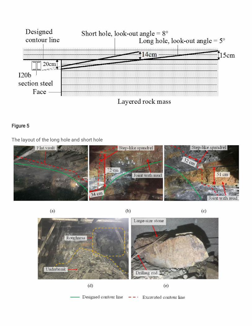
Figure 5
The layout of the long hole and short hole

Figure 6
The failure characteristics of horizontal layered surrounding rock after blasting excavation under theoriginal blasting scheme: (a) vault, (b) left spandrel to haunch, (c) right spandrel to haunch, (d) roughface and underbreak, (e) large-size stone
Figure 7
Field measurements: (a) deformation of surrounding rock and length of each round excavation by usingLeica TCA total station, (b) overbreak and underbreak by using BJSD-3 tunnel section laser
Figure 9
Re�ection and transmission of explosive stress wave passing through weak bedding
Figure 10
Numerical model of tunnel, and the surrounding rock contains horizontal beddings and two sets of joints
Figure 11
Vertical deformations and failure modes after tunnel excavation: (a) surrounding rock with horizontalbeddings, (b) surrounding rock with horizontal beddings and two parallel vertical joints, (c) surroundingrock with horizontal beddings and two sets of intersecting joints
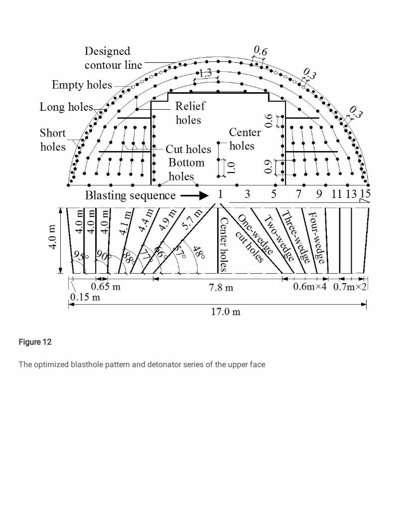
Figure 12
The optimized blasthole pattern and detonator series of the upper face

Figure 13
The layout of the optimized peripheral holes
Figure 14
Relation between charge of peripheral hole and each round excavation length
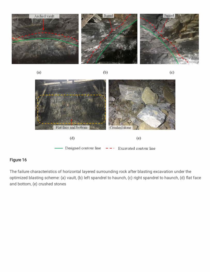
Figure 16
The failure characteristics of horizontal layered surrounding rock after blasting excavation under theoptimized blasting scheme: (a) vault, (b) left spandrel to haunch, (c) right spandrel to haunch, (d) �at faceand bottom, (e) crushed stones

Figure 17
Tunnel overbreak and underbreak of the test sections: (a) ZK80+235.7, (b) ZK80+220.1 (unit: cm)
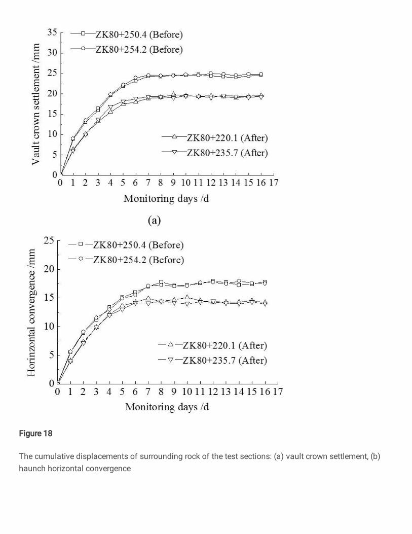
Figure 18
The cumulative displacements of surrounding rock of the test sections: (a) vault crown settlement, (b)haunch horizontal convergence