experimental study on vibration control of shape memory
TRANSCRIPT

EXPERIMENTAL STUDY ON VIBRATION CONTROL OF
SHAPE MEMORY ALLOY ACTUATED FLEXIBLE BEAM
K Dhanalakshmi Aditya Avinash M Umapathy M Marimuthu
Department of Instrumentation and Control Engineering
National Institute of Technology Tiruchirappalli ndash 620 015 TN INDIA
Emails dhanlaknittedu adityaavinash04gmailcom umapathynittedu
Abstract- This paper describes the development of an experimental platform which analyzes
and controls the vibration of a Shape Memory Alloy (SMA) actuated and piezo sensed flexible
beam The vibration is controlled using the interactive force of a pair of almost identical SMA
wires connected in an antagonistic manner arranged in parallel to and on both sides of the
cantilever beam structure Data acquisition and control are implemented using a PCI data
acquisition card and LabVIEW Standard P PI ON-OFF controllers have been used to
control the first mode of vibration of the flexible beam Experimental results are used to
demonstrate the effectiveness of the controllers designed and usefulness of the proposed test
platform by exciting the structure at resonance
Index terms Smart structure Shape Memory Alloy Vibration Control LabVIEW P PI and ON-OFF
controller
I INTRODUCTION
Flexible structures usually have low flexible rigidity and small material damping ratio A little
excitation may lead to destructive large amplitude vibration and long vibration decay time These
can result in fatigue instability and poor operation of the structures Vibration control of flexible
structures is an important issue in many engineering applications especially for the precise
operation performances in aerospace systems satellites flexible manipulators etc [1 2]
Advances in smart materials have produced smaller and effective actuators and sensors with high
integrity in structures
INTERNATIONAL JOURNAL ON SMART SENSING AND INTELLIGENT SYSTEMS VOL 3 NO 2 JUNE 2010
156
Smart material systems offer great possibilities in terms of providing novel and economical
solutions to engineering problems since they offer potential technological advantages over
traditional ones Smart materials such as piezoelectric materials shape memory alloys (SMA)
and magneto- and electro- rheological fluids have been used in diverse areas Varieties of
actuators are developed from smart materials but the more promising are the ones based on
piezoelectric effect of some ceramic materials and secondly the shape memory effect of metallic
alloys Nitinol is the most widely used shape memory alloy due to its superior properties that are
suitable for actuation The significant advantages of SMA wires in comparison to that of
laminated piezoelectric actuator are the relatively low voltage to generate a displacement larger
recovery force generated per unit volume by phase transformation small size high output
excitation actuation for vibration control its large displacement the complete recovery
deformation high stiffness and electrical heating SMA wires have the property of shortening
when heated and thus are able to apply forces This phenomenon called the Shape Memory Effect
(SME) occurs when the material is heated above a certain transition temperature changing its
crystalline phase from martensite to austenite A typical method to trigger the transformations in
SMA includes Joule heating for martensite to austenite transition and air convection cooling for
the reverse transition One of its characteristic being small bandwidth makes it suitable for low
frequency vibration control application [3 - 6]
The efficiency of a shape memory actuator depends on the accuracy of its controls which in turn
depends on the mathematical model of the SMA In structural control applications the SMA wire
linear actuators can be incorporated internal or externally to the structure However external
actuators have better control authority since the actuator can be placed at different offset
distances from the structure The distinctive feature of smart structures is that the actuators and
sensors are often distributedsbquo and have a high degree of integration with the structuresbquo modeling
is thus challenging The dynamics of SMA actuated structures are modeled by using the finite
element method and through system identification [7 8] The model integrates the structural
dynamics with the dynamic characteristics of the SMA and the controller Standard P PI ON-
OFF controllers have been used to control the first mode of vibration of the flexible beam
LabVIEW is highly suitable for virtual instrumentation as very useful user interface can be
designed Using LabVIEW one can create test and measurement data acquisition instrument
control data logging measurement analysis and report generation applications and can also
157
K Dhanalakshmi Aditya Avinash M Umapathy M Marimuthu Experimental Study on Vibration Control of Shape Memory Alloy Actuated Flexible Beam
create stand-alone executables and shared libraries like DLLs because LabVIEW is a true 32-bit
compiler LabVIEW programs are called virtual instruments (VIs) VIs contain three main
components - the front panel the block diagram and the icon and connector pane LabVIEW
provides a good platform for controller design and implementation as it has exclusive toolkits for
control applications and provides an efficient way to design user interfaces for such applications
LabVIEW 86 and its toolkits for control applications like PID control toolkit and control design
and simulation toolkit have been used for computer simulation and for implementation of the
designed controller in real time [9] Data acquisition (DAQ) card PCI 6024E and corresponding
device driver are used to interface the given cantilever beam structure with LabVIEW Standard
P PI ON-OFF controllers have been used to control the first mode of vibration of the flexible
beam P and PI controllers have been implemented using LabVIEW PID control tool kit All the
PID control VIs are reentrant Multiple calls from high-level VIs use separate and distinct data
The organization of this paper is as follows in section 2 the experimental set up of the smart
structure employed for identification and control is described The system models are given in
Section 3 Controller designs and simulation results are reported in Section 4 The experimental
implementation and results are presented in Section 5 followed by the conclusions in Section 6
II THE EXPERIMENTAL SYSTEM
In order to verify the effectiveness of vibration control strategies the experimental setup shown
in Figure 1 (a) is designed and built The setup consists of the following three main parts i) the
beam under test with the PZT elements bonded to its surface and externally connected SMA wire
actuators and the fixture ii) the instrumentation setup ndash a charge amplifier and a voltage
amplifier for the PZT sensor and disturbance actuator current amplifiers for the SMA wire
actuators and the data acquisition board iii) the software interface ndash the visuals and the control
algorithm to process the measured signal and issue the appropriate control signal
A clamped-free aluminum beam fixed vertically along its width is considered in this work Two
collocated piezoceramic patches are surface bonded at a distance of 8 mm from the fixed end the
beam is excited using one piezoceramic patch and the response is sensed using another
Symmetrically mounted antagonistic pair of SMA (NiTiNOL) wires is attached externally to the
beam on both sides to function as control actuators The dimensions and material properties of
INTERNATIONAL JOURNAL ON SMART SENSING AND INTELLIGENT SYSTEMS VOL 3 NO 2 JUNE 2010
158
the beam piezoceramic patches and NiTiNOL wires are listed in Table 1 Table 2 and Table 3
respectively PZT (Lead Zirconate Titanate) of type SP-5H which is equivalent to NAVY TYPE
VI the product from Sparkler Ceramics Pvt Ltd India are used as the sensor and disturbance
actuator Nitinol wires under the trade name Flexinolreg procured from Dynalloy Inc USA are
designed and used as control actuators Flexinol is a binary alloy (Ni-Ti 505ndash495) with a one-
way shape memory effect The arrangement of Nitinol wire actuators is shown in Figure 1 (b)
On each side of the beam a NiTi SMA wire (90C Flexinol) is strung between two terminal points
at the fixed end of the beam and a stub with an offset anchored at the midpoint of the beam
creating two 565 cm parallel lengths of wire In effect each SMA wire is electrically single while
it forms two mechanically parallel wires in equivalent This provides ease of electrical connection
to the SMA wires Such mechanically parallel but electrically serial wires provide the benefit of
producing high output force The usage of two actuator wires allows their alternate heating
and cooling thereby permitting continuous actuation through joule heating Current through
them is routed by software switching so that RMS value of the positive current heats one wire
and the RMS value of negative current commands the other The locations of the sensor and the
actuators have been selected for the best performance
(a)
159
K Dhanalakshmi Aditya Avinash M Umapathy M Marimuthu Experimental Study on Vibration Control of Shape Memory Alloy Actuated Flexible Beam
(b)
Figure 1 Experimental setup (a) Schematic diagram (b) Actuatorsensor location
Table 1 Dimensions and properties of the aluminum beam
Length (m) bl 11
Width (m) bb 00254
Thickness (m) bt
000316
Youngrsquos Modulus (GPa) bE 76
Density (kgm3)
b 29623
First Natural Frequency (Hz) 1f 213
Table 2 Dimensions and properties of the piezoceramic sensoractuator
Length (m) l p 00762
Width (m) pb 00254
Thickness (m) pt 0001
Youngrsquos Modulus (GPa) pE 4762
Density (kgm3)
p 7500
Piezoelectric Strain Constant (m V-1
) 31d
-247x10-12
The excitation signal to the disturbance actuator is applied using an arbitrary waveform generator
(Agilent 33220A) The sensor output signal is conditioned using a piezo sensing system and is
given to the analog input channel of the PCI 6024E DAQ card through SCB 68 connector The
inputs and outputs from the cantilever system are connected to the DAQ card using the SCB 68
connector The input signal is received by the DAQ card and it is sent to the running LabVIEW
program with the help of NI device driver The LabVIEW program receives the sensor output in
appropriate form and it takes the control action based on the input value and control algorithm
INTERNATIONAL JOURNAL ON SMART SENSING AND INTELLIGENT SYSTEMS VOL 3 NO 2 JUNE 2010
160
implemented in the program Controller outputs available at the DAQ card through its two analog
output channels are in terms of voltage The voltage outputs are given to two voltage to current
convertors These V to I convertors supply electrical power to the SMA wires for the control
action The SMA wires used in the experiment should not be heated continuously for more than 1
second So the LabVIEW programs have been designed such that the controllers act alternatively
hence each output channel of DAQ card can send the output for one second and then it remains
inactive for the next one second Photographs of the experimental setup are shown in Figure 2 (a)
and (b) The SMA wires are too thin (01 mm diameter) to be visible in the photograph in Figure
2 (a)
Table 3 Dimensions and properties of the NiTiNOL wire actuator
Length (m) ls 113
Diameter (m) sd 0000127
Transition Temperature (o C)
tT 90
Martensite Start Temperature (o C)
Martensite Finish Temperature (o C)
Austenite Start Temperature (o C)
Austenite Finish Temperature (o C)
sM
fM
sA
fA
72
62
88
98
Youngrsquos modulus (GPa)
Martensite
Austenite
ME
AE
28
75
Resistance (ohmm) sR 70866
Approximate Current at room temperature (A) sI 025
Contraction Time (s) contt 1
Off Time (s) offt 09
Maximum Pull Force (kg) Fmax 0230
161
K Dhanalakshmi Aditya Avinash M Umapathy M Marimuthu Experimental Study on Vibration Control of Shape Memory Alloy Actuated Flexible Beam
(a)
(b)
Figure 2 Photographs of the experimental setup
(a) Structure with electronics (b) PC with LabVIEW and interfacing device
III MODEL OF SYSTEM DYNAMICS
The linear dynamic model of SMA actuated cantilever beam is obtained using online Recursive
Least Square (RLS) parameter estimation as in [10 11] The unknown parameters of the smart
Piezo
sensing
system
Beam
SMA actuation
circuit
SCB 68
Connector
PC with
running
LabVIEW
program
GUI of
the
LabVIEW
program
PCI 6024E
DAQ Card
Control
signals to
SMA wires
PZT sensor
INTERNATIONAL JOURNAL ON SMART SENSING AND INTELLIGENT SYSTEMS VOL 3 NO 2 JUNE 2010
162
structure dynamics are estimated using online identification method since it is proven to be more
universal and feasible than analytical and numerical models for the present system In addition
the RLS method based on Auto-Regressive (ARX) model is used for linear system identification
which is easy to implement and has fast parameter convergence
The ARX model for the system shown in figure 1 is given as
1 11
1
b 11 b
b22 b
n 1
2 2
aay(k) a y(k -1) a y(k - n ) b1 u (k -1) b1 u (k - n ) n
b2 u (k -1) b2 u (k - n )n
1 n e e d(k -1) e d(k - n ) d(k)e
(1)
where 1u (k) and 2u (k) are the input signals y(k) is the piezo sensor output e(k) is the
disturbance input and na b1n
b2n and ne determine the model order
The natural frequency of the structure is measured experimentally as 2355 Hz The first mode
frequency of the structure is measured by sweeping the excitation signal frequency applied to
disturbance actuator from zero until the resonance is observed To identify the parameters online
the structure is excited by a sinusoidal signal through the disturbance actuator and a square wave
signal as input to the control actuators The disturbance signal is in the frequency range of 0 to 20
Hz which includes first two natural frequencies Control actuator (SMA) 1 is excited for a period
of 1 second and for the next 1 second control actuator 2 is actuated by the same square wave
signal The input-output data is then collected The sampling time is set to provide approximately
five measurements per cycle The excitation signal Root Mean Square (RMS) values of the input
signals and sensor output are given to MATLABSimulinkTM
through Analog to Digital
Converter (ADC) port of dSPACE DS1104 system The RLS algorithm is implemented by
writing a C-file S-function be used with Real Time Workshop of MATLABSimulinkTM
The
algorithm is run dynamically until all the parameter values settle down to a final steady value
The model is identified to represent the first vibration mode (second order model) The
continuous time transfer function models derived from the identified second order ARX model
are as follows
Transfer function between output (Y) and control input from SMA actuator 1 (U1) is
ndash 00830 s ndash 56121
------------------------------ (2)
s2
+ 05587 s + 2199986
Transfer function between output (Y) and control input from SMA actuator 2 (U2) is
163
K Dhanalakshmi Aditya Avinash M Umapathy M Marimuthu Experimental Study on Vibration Control of Shape Memory Alloy Actuated Flexible Beam
ndash 00650 s ndash 59204
------------------------------ (3)
s2
+ 05587 s + 2199986
The model has been validated and it is found that the mode frequency obtained from the
identified model is 23379 Hz and is close to the experimentally measured mode frequency 236
Hz
IV DESIGN OF CONTROLLERS
To suppress the amplitude of the vibration at resonance of an SMA actuated cantilever beam the
basic control schemes like the On-Off control proportional control and proportional plus integral
control are designed and simulated The design involves control of the first mode of vibration
using the second order model
a OnOff Controller
In the On-Off controller the controller input is given to the system only when the sensor output
exceeds the given offset The offset value is set on the basis of tolerance value and the system
response to the controller In this controller one SMA wire suppresses the vibrations when the
sensor output is greater than 005 volt while the other SMA wire suppresses the vibrations when
the sensor output is less than ndash 005 volt The two controllers act alternatively with a switching
time of one second The simulation Block Diagram of On-Off controller is shown in Figure 3
(a) The open loop response response with On-Off control and its control signal obtained through
simulation are shown in Figure 3 (b)
INTERNATIONAL JOURNAL ON SMART SENSING AND INTELLIGENT SYSTEMS VOL 3 NO 2 JUNE 2010
164
Figure 3 (a) Block Diagram of On-Off controller (simulation)
Figure 3 (b) Front Panel of On-Off control showing responses and control signals (simulation)
165
K Dhanalakshmi Aditya Avinash M Umapathy M Marimuthu Experimental Study on Vibration Control of Shape Memory Alloy Actuated Flexible Beam
b) Proportional plus Integral (PI) Controller and Proportional (P) Controller
A PI controller is designed to control the actuating force of the SMA wires Figure 7 (a) shows a
conceptual diagram of the closed loop control system including the controller The gain value of
the designed controller was obtained by the pole placement method [10] The damping factor of
the original system is 001884 which is too small Hence the closed loop poles are placed such
that the damping factor is improved to be 06 The designed values are K = 171 Ki = 00161 and
Kd = 0000029 Since Kd is very small the control action is selected to be a PI controller with K =
171 and Ki = 00161 Also the effect of the P controller alone is obtained for only P control
action with the proportional gain K = 171
For simulation of P and PI controller the PID VI is used which is available in the PID control
toolkit The PID gains are set on the front panel The two inputs to the PID VI are PID gains and
the output of the transfer function model The controller output of the PID VI is sent to the M
script code The code inside the M script is responsible for the alternate action of the two
controllers Controller outputs pass through saturation blocks to limit the outputs between 0 to 3
volts The outputs of the simulation blocks are then given to the transfer function model The
controller outputs as well as output of the transfer function model are stored in the excel sheets
during program runtime The front panel displays the open loop response response with
proportional control and its control signals obtained through simulation are shown in Figure 4
INTERNATIONAL JOURNAL ON SMART SENSING AND INTELLIGENT SYSTEMS VOL 3 NO 2 JUNE 2010
166
Figure 4 Front Panel of proportional control showing responses and control signals (simulation)
The open loop response response with PI control and its control signal obtained through
simulation are displayed in the front panel as in Figure 5
167
K Dhanalakshmi Aditya Avinash M Umapathy M Marimuthu Experimental Study on Vibration Control of Shape Memory Alloy Actuated Flexible Beam
Figure 5 Front Panel of PI controller showing responses and control signals (simulation)
V EXPERIMENTAL IMPLEMENTATION
Evaluation of the performance of the controller through experiment is an essential part of the
design To substantiate the design and simulation results the controller designed for the second
order system is implemented using the experimental facility shown in Figure 1 The structure is
made to vibrate at its first mode frequency (236 Hz) by applying a sinusoidal excitation signal
of 1 volt peak to peak to the disturbance actuator from an arbitrary waveform generator (Agilent
33220A) This vibration is sensed by the piezo sensor which gives a corresponding voltage
output This output is connected to the analog input channel of the DAQ card through SCB 68
connector The DAQ assistance VI in the LabVIEW program receives the output of the piezo-
sensing system and it sends the signal to the On-OffPID VI The offset of the On-Off VI and
gains of the PID VI are set on the front panel The controller output is sent to the M script which
implements the alternation action of the two controllers The controller outputs are sent to the
saturation blocks to limit the controller output to the desired range The output of the saturation
blocks are sent to the two DAQ assistance VIs The controller outputs are available from the
INTERNATIONAL JOURNAL ON SMART SENSING AND INTELLIGENT SYSTEMS VOL 3 NO 2 JUNE 2010
168
DAQ card through its two analog output channels and are sent to the V to I convertors through
SCB 68 connector The control signal generated by the controller 1 is applied to actuator 1 at
alternate 1 s while the control signal generated by controller 2 is applied to actuator 2 at the other
alternate 1 second Switching between the controllers is cycled at every consecutive period of 1
second while continuous actuation is provided to the system by the alternate actuators The
controller outputs and the piezo-sensor output are also stored in the excel sheet The plots on the
front panel show the sensor output and the controller outputs The controller is thus implemented
by developing a real time LabVIEW program The open loop response closed loop response with
On-Off control and the corresponding control signals are shown in Figure 6 (a) and (b) The
frequency responses of the system acquired using Digital Storage Oscilloscope (DSO) (Agilent
54621A) are shown in Figure 6 (c)
(a)
169
K Dhanalakshmi Aditya Avinash M Umapathy M Marimuthu Experimental Study on Vibration Control of Shape Memory Alloy Actuated Flexible Beam
(b)
(c)
Figure 6 Experimental implementation and results with On-Off controller
(a) amp (b) Uncontrolled and controlled responses with On-Off controller and control signals
(c) Frequency responses with and without On-Off controller
INTERNATIONAL JOURNAL ON SMART SENSING AND INTELLIGENT SYSTEMS VOL 3 NO 2 JUNE 2010
170
The block diagram model shown in Figure 7 (a) is developed using LabVIEW for implementing
the PI controller in real time The open loop response closed loop response with proportional
control and the control signals are shown in Figure 7 (b) and the frequency responses of the
system acquired using DSO are shown in Figure 7 (c)
(a)
Data
acquisition
VIs
PID VI
used for PI
controller
Simulation
Loop
VI to save the
data in excel
sheets
Data
aquition
VIs
171
K Dhanalakshmi Aditya Avinash M Umapathy M Marimuthu Experimental Study on Vibration Control of Shape Memory Alloy Actuated Flexible Beam
(b)
(c)
Figure 7 Experimental implementation and results with P controller
(a) Real-time block diagram for PI controller in LabVIEW
(b) Uncontrolled and controlled responses with proportional controller and control signals
(c) Frequency responses with and without proportional controller
Similarly the open loop response closed loop response with proportional plus integral control
and the control signals are shown in Figure 8 (a) and its frequency response is shown in Figure 8
(b)
INTERNATIONAL JOURNAL ON SMART SENSING AND INTELLIGENT SYSTEMS VOL 3 NO 2 JUNE 2010
172
(a)
(b)
Figure 8 (a) Experimental results with proportional plus integral controller
(b) Frequency responses with and without PI controller
173
K Dhanalakshmi Aditya Avinash M Umapathy M Marimuthu Experimental Study on Vibration Control of Shape Memory Alloy Actuated Flexible Beam
VI CONCLUSIONS
The second order model of SMA actuated and piezoelectric sensed cantilever beam structure
excited at its first mode of resonant frequency has been identified using online ARX RLS system
identification approach The On-Off P and PI controllers have been designed and implemented
experimentally using LabVIEW 86 for the system model Controllers like the On-off which is
the simplest form of control proportional controller which attempts to perform better than the
On-Off type and the PI form of PID controller are designed simulated and implemented on the
system developed to demonstrate the vibration control strategies The closed loop responses
obtained through simulation with these control actions closely matches with that of the
experimental results for the system The closeness depends on suitable design and the selection of
control parameters For a sinusoidal excitation of 1 volt peak to peak an uncontrolled response of
0225 V peak to peak is obtained In the problem of first mode vibration control the following
reduction in amplitude of vibration is through simulation and experimentally
Control
Vibration reduction
Simulation Experiment
On-Off 80 78
Proportional 79 77
PI 82 80
The simulation and experimental results demonstrate the performance and practical simplicity of
the controller design and implementation using LabVIEW Experimental results show that the
closed loop response obtained with these control schemes exhibits substantial reduction in the
amplitude of flexural vibration at its first mode resonance The application programs made here
in LabVIEW use the software timing for timing related requirements But software timing is
affected by various factors like other processes run by operating system system hardware
specifications user interference etc Hence better vibration control can be achieved by
implementing hardware timing and by the use of real time systems like Compact RIO controller
[9] In this paper only basic controllers have been implemented which have various inherent
limitations hence advanced controllers can be implemented During the experimental study it has
been found that LabVIEW provides a very good platform to develop controllers and to
implement the designed controllers in real time very easily and efficiently
INTERNATIONAL JOURNAL ON SMART SENSING AND INTELLIGENT SYSTEMS VOL 3 NO 2 JUNE 2010
174
ACKNOWLEDGEMENT
The authors wish to acknowledge the funding from Indian Space Research Organization (ISRO)
RESPOND scheme for the support of this research
REFERENCES
[1] A Srinivasan and D McFarland ldquoSmart Structure Analysis and Designrdquo Cambridge
University Press 2001
[2] T Waram ldquoActuator design using Shape Memory Alloysrdquo Mondotronics Inc Canada
second edition 1993
[3] A Baz K Imam and J McCoy ldquoActive Vibration Control of Flexible Beams using Shape
Memory Actuatorsrdquo Journal of Sound and Vibration Vol 140 Issue 3 1990 pp 437 ndash 456
[4] Seung-Bok Choi and Chae-Cheon Cheong ldquoVibration control of a Flexible Beam using
Shape Memory Alloy Actuatorsrdquo Journal of Guidance Control and Dynamics Vol 19 Issue 5
1996 pp1178 ndash 1180
[5] Stefan Seelecke and Ingo Muller ldquoShape memory alloy actuators in smart structures
Modeling and Simulationrdquo ASME Vol 57 Issue 1 2004 pp 23 ndash 46
[6] J W Sohn Y M Han and S B Choi ldquoVibration and position tracking control of flexible
beam using SMA wire actuatorsrdquo Journal of Vibration and Control Vol 15 Issue 2 2009 pp
263-281
[7] Kyoung Kwan Ahn and Nguyen Bao Kha ldquoPredictive control for shape memory alloy
actuatorsrdquo Proceedings of the International Symposium on Electrical and Electronics
Engineering HCM City Vietnam 11-12 October 2005 pp 30-35
[8] D Ezhilarasi M Umapathy and BBandyopadhyay ldquoDesign and experimental evaluation of
piecewise output feedback control for structural vibration suppression using PZT patchesrdquo
Journal of Smart Materials and Structures Vol 15 2006 pp 1927 ndash 1938
[9] LabVIEW 86 User Manual NI LabVIEW Data Acquisition manual NI LabVIEW
Simulation and Design Toolkit Manual NI LabVIEW PID Control Toolkit Manual National
Instruments web portal (httpwwwnicom)
[10] Karl J Astrom and Tore Hagglund ldquoPID Controllers Theory Design and Tuningrdquo
International Society for Measurement and Control 2nd Sub edition 1995
175
K Dhanalakshmi Aditya Avinash M Umapathy M Marimuthu Experimental Study on Vibration Control of Shape Memory Alloy Actuated Flexible Beam

(b)
Figure 1 Experimental setup (a) Schematic diagram (b) Actuatorsensor location
Table 1 Dimensions and properties of the aluminum beam
Length (m) bl 11
Width (m) bb 00254
Thickness (m) bt
000316
Youngrsquos Modulus (GPa) bE 76
Density (kgm3)
b 29623
First Natural Frequency (Hz) 1f 213
Table 2 Dimensions and properties of the piezoceramic sensoractuator
Length (m) l p 00762
Width (m) pb 00254
Thickness (m) pt 0001
Youngrsquos Modulus (GPa) pE 4762
Density (kgm3)
p 7500
Piezoelectric Strain Constant (m V-1
) 31d
-247x10-12
The excitation signal to the disturbance actuator is applied using an arbitrary waveform generator
(Agilent 33220A) The sensor output signal is conditioned using a piezo sensing system and is
given to the analog input channel of the PCI 6024E DAQ card through SCB 68 connector The
inputs and outputs from the cantilever system are connected to the DAQ card using the SCB 68
connector The input signal is received by the DAQ card and it is sent to the running LabVIEW
program with the help of NI device driver The LabVIEW program receives the sensor output in
appropriate form and it takes the control action based on the input value and control algorithm
INTERNATIONAL JOURNAL ON SMART SENSING AND INTELLIGENT SYSTEMS VOL 3 NO 2 JUNE 2010
160
implemented in the program Controller outputs available at the DAQ card through its two analog
output channels are in terms of voltage The voltage outputs are given to two voltage to current
convertors These V to I convertors supply electrical power to the SMA wires for the control
action The SMA wires used in the experiment should not be heated continuously for more than 1
second So the LabVIEW programs have been designed such that the controllers act alternatively
hence each output channel of DAQ card can send the output for one second and then it remains
inactive for the next one second Photographs of the experimental setup are shown in Figure 2 (a)
and (b) The SMA wires are too thin (01 mm diameter) to be visible in the photograph in Figure
2 (a)
Table 3 Dimensions and properties of the NiTiNOL wire actuator
Length (m) ls 113
Diameter (m) sd 0000127
Transition Temperature (o C)
tT 90
Martensite Start Temperature (o C)
Martensite Finish Temperature (o C)
Austenite Start Temperature (o C)
Austenite Finish Temperature (o C)
sM
fM
sA
fA
72
62
88
98
Youngrsquos modulus (GPa)
Martensite
Austenite
ME
AE
28
75
Resistance (ohmm) sR 70866
Approximate Current at room temperature (A) sI 025
Contraction Time (s) contt 1
Off Time (s) offt 09
Maximum Pull Force (kg) Fmax 0230
161
K Dhanalakshmi Aditya Avinash M Umapathy M Marimuthu Experimental Study on Vibration Control of Shape Memory Alloy Actuated Flexible Beam
(a)
(b)
Figure 2 Photographs of the experimental setup
(a) Structure with electronics (b) PC with LabVIEW and interfacing device
III MODEL OF SYSTEM DYNAMICS
The linear dynamic model of SMA actuated cantilever beam is obtained using online Recursive
Least Square (RLS) parameter estimation as in [10 11] The unknown parameters of the smart
Piezo
sensing
system
Beam
SMA actuation
circuit
SCB 68
Connector
PC with
running
LabVIEW
program
GUI of
the
LabVIEW
program
PCI 6024E
DAQ Card
Control
signals to
SMA wires
PZT sensor
INTERNATIONAL JOURNAL ON SMART SENSING AND INTELLIGENT SYSTEMS VOL 3 NO 2 JUNE 2010
162
structure dynamics are estimated using online identification method since it is proven to be more
universal and feasible than analytical and numerical models for the present system In addition
the RLS method based on Auto-Regressive (ARX) model is used for linear system identification
which is easy to implement and has fast parameter convergence
The ARX model for the system shown in figure 1 is given as
1 11
1
b 11 b
b22 b
n 1
2 2
aay(k) a y(k -1) a y(k - n ) b1 u (k -1) b1 u (k - n ) n
b2 u (k -1) b2 u (k - n )n
1 n e e d(k -1) e d(k - n ) d(k)e
(1)
where 1u (k) and 2u (k) are the input signals y(k) is the piezo sensor output e(k) is the
disturbance input and na b1n
b2n and ne determine the model order
The natural frequency of the structure is measured experimentally as 2355 Hz The first mode
frequency of the structure is measured by sweeping the excitation signal frequency applied to
disturbance actuator from zero until the resonance is observed To identify the parameters online
the structure is excited by a sinusoidal signal through the disturbance actuator and a square wave
signal as input to the control actuators The disturbance signal is in the frequency range of 0 to 20
Hz which includes first two natural frequencies Control actuator (SMA) 1 is excited for a period
of 1 second and for the next 1 second control actuator 2 is actuated by the same square wave
signal The input-output data is then collected The sampling time is set to provide approximately
five measurements per cycle The excitation signal Root Mean Square (RMS) values of the input
signals and sensor output are given to MATLABSimulinkTM
through Analog to Digital
Converter (ADC) port of dSPACE DS1104 system The RLS algorithm is implemented by
writing a C-file S-function be used with Real Time Workshop of MATLABSimulinkTM
The
algorithm is run dynamically until all the parameter values settle down to a final steady value
The model is identified to represent the first vibration mode (second order model) The
continuous time transfer function models derived from the identified second order ARX model
are as follows
Transfer function between output (Y) and control input from SMA actuator 1 (U1) is
ndash 00830 s ndash 56121
------------------------------ (2)
s2
+ 05587 s + 2199986
Transfer function between output (Y) and control input from SMA actuator 2 (U2) is
163
K Dhanalakshmi Aditya Avinash M Umapathy M Marimuthu Experimental Study on Vibration Control of Shape Memory Alloy Actuated Flexible Beam
ndash 00650 s ndash 59204
------------------------------ (3)
s2
+ 05587 s + 2199986
The model has been validated and it is found that the mode frequency obtained from the
identified model is 23379 Hz and is close to the experimentally measured mode frequency 236
Hz
IV DESIGN OF CONTROLLERS
To suppress the amplitude of the vibration at resonance of an SMA actuated cantilever beam the
basic control schemes like the On-Off control proportional control and proportional plus integral
control are designed and simulated The design involves control of the first mode of vibration
using the second order model
a OnOff Controller
In the On-Off controller the controller input is given to the system only when the sensor output
exceeds the given offset The offset value is set on the basis of tolerance value and the system
response to the controller In this controller one SMA wire suppresses the vibrations when the
sensor output is greater than 005 volt while the other SMA wire suppresses the vibrations when
the sensor output is less than ndash 005 volt The two controllers act alternatively with a switching
time of one second The simulation Block Diagram of On-Off controller is shown in Figure 3
(a) The open loop response response with On-Off control and its control signal obtained through
simulation are shown in Figure 3 (b)
INTERNATIONAL JOURNAL ON SMART SENSING AND INTELLIGENT SYSTEMS VOL 3 NO 2 JUNE 2010
164
Figure 3 (a) Block Diagram of On-Off controller (simulation)
Figure 3 (b) Front Panel of On-Off control showing responses and control signals (simulation)
165
K Dhanalakshmi Aditya Avinash M Umapathy M Marimuthu Experimental Study on Vibration Control of Shape Memory Alloy Actuated Flexible Beam
b) Proportional plus Integral (PI) Controller and Proportional (P) Controller
A PI controller is designed to control the actuating force of the SMA wires Figure 7 (a) shows a
conceptual diagram of the closed loop control system including the controller The gain value of
the designed controller was obtained by the pole placement method [10] The damping factor of
the original system is 001884 which is too small Hence the closed loop poles are placed such
that the damping factor is improved to be 06 The designed values are K = 171 Ki = 00161 and
Kd = 0000029 Since Kd is very small the control action is selected to be a PI controller with K =
171 and Ki = 00161 Also the effect of the P controller alone is obtained for only P control
action with the proportional gain K = 171
For simulation of P and PI controller the PID VI is used which is available in the PID control
toolkit The PID gains are set on the front panel The two inputs to the PID VI are PID gains and
the output of the transfer function model The controller output of the PID VI is sent to the M
script code The code inside the M script is responsible for the alternate action of the two
controllers Controller outputs pass through saturation blocks to limit the outputs between 0 to 3
volts The outputs of the simulation blocks are then given to the transfer function model The
controller outputs as well as output of the transfer function model are stored in the excel sheets
during program runtime The front panel displays the open loop response response with
proportional control and its control signals obtained through simulation are shown in Figure 4
INTERNATIONAL JOURNAL ON SMART SENSING AND INTELLIGENT SYSTEMS VOL 3 NO 2 JUNE 2010
166
Figure 4 Front Panel of proportional control showing responses and control signals (simulation)
The open loop response response with PI control and its control signal obtained through
simulation are displayed in the front panel as in Figure 5
167
K Dhanalakshmi Aditya Avinash M Umapathy M Marimuthu Experimental Study on Vibration Control of Shape Memory Alloy Actuated Flexible Beam
Figure 5 Front Panel of PI controller showing responses and control signals (simulation)
V EXPERIMENTAL IMPLEMENTATION
Evaluation of the performance of the controller through experiment is an essential part of the
design To substantiate the design and simulation results the controller designed for the second
order system is implemented using the experimental facility shown in Figure 1 The structure is
made to vibrate at its first mode frequency (236 Hz) by applying a sinusoidal excitation signal
of 1 volt peak to peak to the disturbance actuator from an arbitrary waveform generator (Agilent
33220A) This vibration is sensed by the piezo sensor which gives a corresponding voltage
output This output is connected to the analog input channel of the DAQ card through SCB 68
connector The DAQ assistance VI in the LabVIEW program receives the output of the piezo-
sensing system and it sends the signal to the On-OffPID VI The offset of the On-Off VI and
gains of the PID VI are set on the front panel The controller output is sent to the M script which
implements the alternation action of the two controllers The controller outputs are sent to the
saturation blocks to limit the controller output to the desired range The output of the saturation
blocks are sent to the two DAQ assistance VIs The controller outputs are available from the
INTERNATIONAL JOURNAL ON SMART SENSING AND INTELLIGENT SYSTEMS VOL 3 NO 2 JUNE 2010
168
DAQ card through its two analog output channels and are sent to the V to I convertors through
SCB 68 connector The control signal generated by the controller 1 is applied to actuator 1 at
alternate 1 s while the control signal generated by controller 2 is applied to actuator 2 at the other
alternate 1 second Switching between the controllers is cycled at every consecutive period of 1
second while continuous actuation is provided to the system by the alternate actuators The
controller outputs and the piezo-sensor output are also stored in the excel sheet The plots on the
front panel show the sensor output and the controller outputs The controller is thus implemented
by developing a real time LabVIEW program The open loop response closed loop response with
On-Off control and the corresponding control signals are shown in Figure 6 (a) and (b) The
frequency responses of the system acquired using Digital Storage Oscilloscope (DSO) (Agilent
54621A) are shown in Figure 6 (c)
(a)
169
K Dhanalakshmi Aditya Avinash M Umapathy M Marimuthu Experimental Study on Vibration Control of Shape Memory Alloy Actuated Flexible Beam
(b)
(c)
Figure 6 Experimental implementation and results with On-Off controller
(a) amp (b) Uncontrolled and controlled responses with On-Off controller and control signals
(c) Frequency responses with and without On-Off controller
INTERNATIONAL JOURNAL ON SMART SENSING AND INTELLIGENT SYSTEMS VOL 3 NO 2 JUNE 2010
170
The block diagram model shown in Figure 7 (a) is developed using LabVIEW for implementing
the PI controller in real time The open loop response closed loop response with proportional
control and the control signals are shown in Figure 7 (b) and the frequency responses of the
system acquired using DSO are shown in Figure 7 (c)
(a)
Data
acquisition
VIs
PID VI
used for PI
controller
Simulation
Loop
VI to save the
data in excel
sheets
Data
aquition
VIs
171
K Dhanalakshmi Aditya Avinash M Umapathy M Marimuthu Experimental Study on Vibration Control of Shape Memory Alloy Actuated Flexible Beam
(b)
(c)
Figure 7 Experimental implementation and results with P controller
(a) Real-time block diagram for PI controller in LabVIEW
(b) Uncontrolled and controlled responses with proportional controller and control signals
(c) Frequency responses with and without proportional controller
Similarly the open loop response closed loop response with proportional plus integral control
and the control signals are shown in Figure 8 (a) and its frequency response is shown in Figure 8
(b)
INTERNATIONAL JOURNAL ON SMART SENSING AND INTELLIGENT SYSTEMS VOL 3 NO 2 JUNE 2010
172
(a)
(b)
Figure 8 (a) Experimental results with proportional plus integral controller
(b) Frequency responses with and without PI controller
173
K Dhanalakshmi Aditya Avinash M Umapathy M Marimuthu Experimental Study on Vibration Control of Shape Memory Alloy Actuated Flexible Beam
VI CONCLUSIONS
The second order model of SMA actuated and piezoelectric sensed cantilever beam structure
excited at its first mode of resonant frequency has been identified using online ARX RLS system
identification approach The On-Off P and PI controllers have been designed and implemented
experimentally using LabVIEW 86 for the system model Controllers like the On-off which is
the simplest form of control proportional controller which attempts to perform better than the
On-Off type and the PI form of PID controller are designed simulated and implemented on the
system developed to demonstrate the vibration control strategies The closed loop responses
obtained through simulation with these control actions closely matches with that of the
experimental results for the system The closeness depends on suitable design and the selection of
control parameters For a sinusoidal excitation of 1 volt peak to peak an uncontrolled response of
0225 V peak to peak is obtained In the problem of first mode vibration control the following
reduction in amplitude of vibration is through simulation and experimentally
Control
Vibration reduction
Simulation Experiment
On-Off 80 78
Proportional 79 77
PI 82 80
The simulation and experimental results demonstrate the performance and practical simplicity of
the controller design and implementation using LabVIEW Experimental results show that the
closed loop response obtained with these control schemes exhibits substantial reduction in the
amplitude of flexural vibration at its first mode resonance The application programs made here
in LabVIEW use the software timing for timing related requirements But software timing is
affected by various factors like other processes run by operating system system hardware
specifications user interference etc Hence better vibration control can be achieved by
implementing hardware timing and by the use of real time systems like Compact RIO controller
[9] In this paper only basic controllers have been implemented which have various inherent
limitations hence advanced controllers can be implemented During the experimental study it has
been found that LabVIEW provides a very good platform to develop controllers and to
implement the designed controllers in real time very easily and efficiently
INTERNATIONAL JOURNAL ON SMART SENSING AND INTELLIGENT SYSTEMS VOL 3 NO 2 JUNE 2010
174
ACKNOWLEDGEMENT
The authors wish to acknowledge the funding from Indian Space Research Organization (ISRO)
RESPOND scheme for the support of this research
REFERENCES
[1] A Srinivasan and D McFarland ldquoSmart Structure Analysis and Designrdquo Cambridge
University Press 2001
[2] T Waram ldquoActuator design using Shape Memory Alloysrdquo Mondotronics Inc Canada
second edition 1993
[3] A Baz K Imam and J McCoy ldquoActive Vibration Control of Flexible Beams using Shape
Memory Actuatorsrdquo Journal of Sound and Vibration Vol 140 Issue 3 1990 pp 437 ndash 456
[4] Seung-Bok Choi and Chae-Cheon Cheong ldquoVibration control of a Flexible Beam using
Shape Memory Alloy Actuatorsrdquo Journal of Guidance Control and Dynamics Vol 19 Issue 5
1996 pp1178 ndash 1180
[5] Stefan Seelecke and Ingo Muller ldquoShape memory alloy actuators in smart structures
Modeling and Simulationrdquo ASME Vol 57 Issue 1 2004 pp 23 ndash 46
[6] J W Sohn Y M Han and S B Choi ldquoVibration and position tracking control of flexible
beam using SMA wire actuatorsrdquo Journal of Vibration and Control Vol 15 Issue 2 2009 pp
263-281
[7] Kyoung Kwan Ahn and Nguyen Bao Kha ldquoPredictive control for shape memory alloy
actuatorsrdquo Proceedings of the International Symposium on Electrical and Electronics
Engineering HCM City Vietnam 11-12 October 2005 pp 30-35
[8] D Ezhilarasi M Umapathy and BBandyopadhyay ldquoDesign and experimental evaluation of
piecewise output feedback control for structural vibration suppression using PZT patchesrdquo
Journal of Smart Materials and Structures Vol 15 2006 pp 1927 ndash 1938
[9] LabVIEW 86 User Manual NI LabVIEW Data Acquisition manual NI LabVIEW
Simulation and Design Toolkit Manual NI LabVIEW PID Control Toolkit Manual National
Instruments web portal (httpwwwnicom)
[10] Karl J Astrom and Tore Hagglund ldquoPID Controllers Theory Design and Tuningrdquo
International Society for Measurement and Control 2nd Sub edition 1995
175
K Dhanalakshmi Aditya Avinash M Umapathy M Marimuthu Experimental Study on Vibration Control of Shape Memory Alloy Actuated Flexible Beam
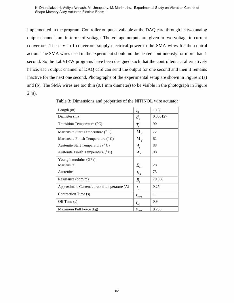
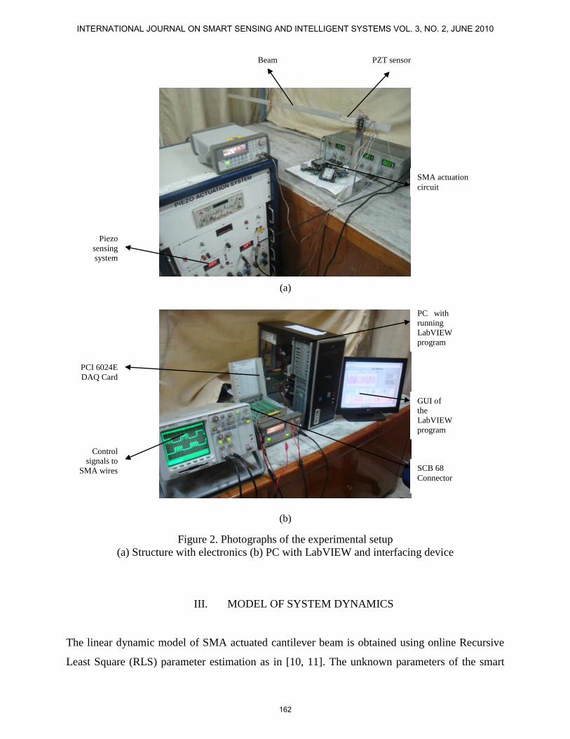
(a)
(b)
Figure 2 Photographs of the experimental setup
(a) Structure with electronics (b) PC with LabVIEW and interfacing device
III MODEL OF SYSTEM DYNAMICS
The linear dynamic model of SMA actuated cantilever beam is obtained using online Recursive
Least Square (RLS) parameter estimation as in [10 11] The unknown parameters of the smart
Piezo
sensing
system
Beam
SMA actuation
circuit
SCB 68
Connector
PC with
running
LabVIEW
program
GUI of
the
LabVIEW
program
PCI 6024E
DAQ Card
Control
signals to
SMA wires
PZT sensor
INTERNATIONAL JOURNAL ON SMART SENSING AND INTELLIGENT SYSTEMS VOL 3 NO 2 JUNE 2010
162
structure dynamics are estimated using online identification method since it is proven to be more
universal and feasible than analytical and numerical models for the present system In addition
the RLS method based on Auto-Regressive (ARX) model is used for linear system identification
which is easy to implement and has fast parameter convergence
The ARX model for the system shown in figure 1 is given as
1 11
1
b 11 b
b22 b
n 1
2 2
aay(k) a y(k -1) a y(k - n ) b1 u (k -1) b1 u (k - n ) n
b2 u (k -1) b2 u (k - n )n
1 n e e d(k -1) e d(k - n ) d(k)e
(1)
where 1u (k) and 2u (k) are the input signals y(k) is the piezo sensor output e(k) is the
disturbance input and na b1n
b2n and ne determine the model order
The natural frequency of the structure is measured experimentally as 2355 Hz The first mode
frequency of the structure is measured by sweeping the excitation signal frequency applied to
disturbance actuator from zero until the resonance is observed To identify the parameters online
the structure is excited by a sinusoidal signal through the disturbance actuator and a square wave
signal as input to the control actuators The disturbance signal is in the frequency range of 0 to 20
Hz which includes first two natural frequencies Control actuator (SMA) 1 is excited for a period
of 1 second and for the next 1 second control actuator 2 is actuated by the same square wave
signal The input-output data is then collected The sampling time is set to provide approximately
five measurements per cycle The excitation signal Root Mean Square (RMS) values of the input
signals and sensor output are given to MATLABSimulinkTM
through Analog to Digital
Converter (ADC) port of dSPACE DS1104 system The RLS algorithm is implemented by
writing a C-file S-function be used with Real Time Workshop of MATLABSimulinkTM
The
algorithm is run dynamically until all the parameter values settle down to a final steady value
The model is identified to represent the first vibration mode (second order model) The
continuous time transfer function models derived from the identified second order ARX model
are as follows
Transfer function between output (Y) and control input from SMA actuator 1 (U1) is
ndash 00830 s ndash 56121
------------------------------ (2)
s2
+ 05587 s + 2199986
Transfer function between output (Y) and control input from SMA actuator 2 (U2) is
163
K Dhanalakshmi Aditya Avinash M Umapathy M Marimuthu Experimental Study on Vibration Control of Shape Memory Alloy Actuated Flexible Beam
ndash 00650 s ndash 59204
------------------------------ (3)
s2
+ 05587 s + 2199986
The model has been validated and it is found that the mode frequency obtained from the
identified model is 23379 Hz and is close to the experimentally measured mode frequency 236
Hz
IV DESIGN OF CONTROLLERS
To suppress the amplitude of the vibration at resonance of an SMA actuated cantilever beam the
basic control schemes like the On-Off control proportional control and proportional plus integral
control are designed and simulated The design involves control of the first mode of vibration
using the second order model
a OnOff Controller
In the On-Off controller the controller input is given to the system only when the sensor output
exceeds the given offset The offset value is set on the basis of tolerance value and the system
response to the controller In this controller one SMA wire suppresses the vibrations when the
sensor output is greater than 005 volt while the other SMA wire suppresses the vibrations when
the sensor output is less than ndash 005 volt The two controllers act alternatively with a switching
time of one second The simulation Block Diagram of On-Off controller is shown in Figure 3
(a) The open loop response response with On-Off control and its control signal obtained through
simulation are shown in Figure 3 (b)
INTERNATIONAL JOURNAL ON SMART SENSING AND INTELLIGENT SYSTEMS VOL 3 NO 2 JUNE 2010
164
Figure 3 (a) Block Diagram of On-Off controller (simulation)
Figure 3 (b) Front Panel of On-Off control showing responses and control signals (simulation)
165
K Dhanalakshmi Aditya Avinash M Umapathy M Marimuthu Experimental Study on Vibration Control of Shape Memory Alloy Actuated Flexible Beam
b) Proportional plus Integral (PI) Controller and Proportional (P) Controller
A PI controller is designed to control the actuating force of the SMA wires Figure 7 (a) shows a
conceptual diagram of the closed loop control system including the controller The gain value of
the designed controller was obtained by the pole placement method [10] The damping factor of
the original system is 001884 which is too small Hence the closed loop poles are placed such
that the damping factor is improved to be 06 The designed values are K = 171 Ki = 00161 and
Kd = 0000029 Since Kd is very small the control action is selected to be a PI controller with K =
171 and Ki = 00161 Also the effect of the P controller alone is obtained for only P control
action with the proportional gain K = 171
For simulation of P and PI controller the PID VI is used which is available in the PID control
toolkit The PID gains are set on the front panel The two inputs to the PID VI are PID gains and
the output of the transfer function model The controller output of the PID VI is sent to the M
script code The code inside the M script is responsible for the alternate action of the two
controllers Controller outputs pass through saturation blocks to limit the outputs between 0 to 3
volts The outputs of the simulation blocks are then given to the transfer function model The
controller outputs as well as output of the transfer function model are stored in the excel sheets
during program runtime The front panel displays the open loop response response with
proportional control and its control signals obtained through simulation are shown in Figure 4
INTERNATIONAL JOURNAL ON SMART SENSING AND INTELLIGENT SYSTEMS VOL 3 NO 2 JUNE 2010
166
Figure 4 Front Panel of proportional control showing responses and control signals (simulation)
The open loop response response with PI control and its control signal obtained through
simulation are displayed in the front panel as in Figure 5
167
K Dhanalakshmi Aditya Avinash M Umapathy M Marimuthu Experimental Study on Vibration Control of Shape Memory Alloy Actuated Flexible Beam
Figure 5 Front Panel of PI controller showing responses and control signals (simulation)
V EXPERIMENTAL IMPLEMENTATION
Evaluation of the performance of the controller through experiment is an essential part of the
design To substantiate the design and simulation results the controller designed for the second
order system is implemented using the experimental facility shown in Figure 1 The structure is
made to vibrate at its first mode frequency (236 Hz) by applying a sinusoidal excitation signal
of 1 volt peak to peak to the disturbance actuator from an arbitrary waveform generator (Agilent
33220A) This vibration is sensed by the piezo sensor which gives a corresponding voltage
output This output is connected to the analog input channel of the DAQ card through SCB 68
connector The DAQ assistance VI in the LabVIEW program receives the output of the piezo-
sensing system and it sends the signal to the On-OffPID VI The offset of the On-Off VI and
gains of the PID VI are set on the front panel The controller output is sent to the M script which
implements the alternation action of the two controllers The controller outputs are sent to the
saturation blocks to limit the controller output to the desired range The output of the saturation
blocks are sent to the two DAQ assistance VIs The controller outputs are available from the
INTERNATIONAL JOURNAL ON SMART SENSING AND INTELLIGENT SYSTEMS VOL 3 NO 2 JUNE 2010
168
DAQ card through its two analog output channels and are sent to the V to I convertors through
SCB 68 connector The control signal generated by the controller 1 is applied to actuator 1 at
alternate 1 s while the control signal generated by controller 2 is applied to actuator 2 at the other
alternate 1 second Switching between the controllers is cycled at every consecutive period of 1
second while continuous actuation is provided to the system by the alternate actuators The
controller outputs and the piezo-sensor output are also stored in the excel sheet The plots on the
front panel show the sensor output and the controller outputs The controller is thus implemented
by developing a real time LabVIEW program The open loop response closed loop response with
On-Off control and the corresponding control signals are shown in Figure 6 (a) and (b) The
frequency responses of the system acquired using Digital Storage Oscilloscope (DSO) (Agilent
54621A) are shown in Figure 6 (c)
(a)
169
K Dhanalakshmi Aditya Avinash M Umapathy M Marimuthu Experimental Study on Vibration Control of Shape Memory Alloy Actuated Flexible Beam
(b)
(c)
Figure 6 Experimental implementation and results with On-Off controller
(a) amp (b) Uncontrolled and controlled responses with On-Off controller and control signals
(c) Frequency responses with and without On-Off controller
INTERNATIONAL JOURNAL ON SMART SENSING AND INTELLIGENT SYSTEMS VOL 3 NO 2 JUNE 2010
170
The block diagram model shown in Figure 7 (a) is developed using LabVIEW for implementing
the PI controller in real time The open loop response closed loop response with proportional
control and the control signals are shown in Figure 7 (b) and the frequency responses of the
system acquired using DSO are shown in Figure 7 (c)
(a)
Data
acquisition
VIs
PID VI
used for PI
controller
Simulation
Loop
VI to save the
data in excel
sheets
Data
aquition
VIs
171
K Dhanalakshmi Aditya Avinash M Umapathy M Marimuthu Experimental Study on Vibration Control of Shape Memory Alloy Actuated Flexible Beam
(b)
(c)
Figure 7 Experimental implementation and results with P controller
(a) Real-time block diagram for PI controller in LabVIEW
(b) Uncontrolled and controlled responses with proportional controller and control signals
(c) Frequency responses with and without proportional controller
Similarly the open loop response closed loop response with proportional plus integral control
and the control signals are shown in Figure 8 (a) and its frequency response is shown in Figure 8
(b)
INTERNATIONAL JOURNAL ON SMART SENSING AND INTELLIGENT SYSTEMS VOL 3 NO 2 JUNE 2010
172
(a)
(b)
Figure 8 (a) Experimental results with proportional plus integral controller
(b) Frequency responses with and without PI controller
173
K Dhanalakshmi Aditya Avinash M Umapathy M Marimuthu Experimental Study on Vibration Control of Shape Memory Alloy Actuated Flexible Beam
VI CONCLUSIONS
The second order model of SMA actuated and piezoelectric sensed cantilever beam structure
excited at its first mode of resonant frequency has been identified using online ARX RLS system
identification approach The On-Off P and PI controllers have been designed and implemented
experimentally using LabVIEW 86 for the system model Controllers like the On-off which is
the simplest form of control proportional controller which attempts to perform better than the
On-Off type and the PI form of PID controller are designed simulated and implemented on the
system developed to demonstrate the vibration control strategies The closed loop responses
obtained through simulation with these control actions closely matches with that of the
experimental results for the system The closeness depends on suitable design and the selection of
control parameters For a sinusoidal excitation of 1 volt peak to peak an uncontrolled response of
0225 V peak to peak is obtained In the problem of first mode vibration control the following
reduction in amplitude of vibration is through simulation and experimentally
Control
Vibration reduction
Simulation Experiment
On-Off 80 78
Proportional 79 77
PI 82 80
The simulation and experimental results demonstrate the performance and practical simplicity of
the controller design and implementation using LabVIEW Experimental results show that the
closed loop response obtained with these control schemes exhibits substantial reduction in the
amplitude of flexural vibration at its first mode resonance The application programs made here
in LabVIEW use the software timing for timing related requirements But software timing is
affected by various factors like other processes run by operating system system hardware
specifications user interference etc Hence better vibration control can be achieved by
implementing hardware timing and by the use of real time systems like Compact RIO controller
[9] In this paper only basic controllers have been implemented which have various inherent
limitations hence advanced controllers can be implemented During the experimental study it has
been found that LabVIEW provides a very good platform to develop controllers and to
implement the designed controllers in real time very easily and efficiently
INTERNATIONAL JOURNAL ON SMART SENSING AND INTELLIGENT SYSTEMS VOL 3 NO 2 JUNE 2010
174
ACKNOWLEDGEMENT
The authors wish to acknowledge the funding from Indian Space Research Organization (ISRO)
RESPOND scheme for the support of this research
REFERENCES
[1] A Srinivasan and D McFarland ldquoSmart Structure Analysis and Designrdquo Cambridge
University Press 2001
[2] T Waram ldquoActuator design using Shape Memory Alloysrdquo Mondotronics Inc Canada
second edition 1993
[3] A Baz K Imam and J McCoy ldquoActive Vibration Control of Flexible Beams using Shape
Memory Actuatorsrdquo Journal of Sound and Vibration Vol 140 Issue 3 1990 pp 437 ndash 456
[4] Seung-Bok Choi and Chae-Cheon Cheong ldquoVibration control of a Flexible Beam using
Shape Memory Alloy Actuatorsrdquo Journal of Guidance Control and Dynamics Vol 19 Issue 5
1996 pp1178 ndash 1180
[5] Stefan Seelecke and Ingo Muller ldquoShape memory alloy actuators in smart structures
Modeling and Simulationrdquo ASME Vol 57 Issue 1 2004 pp 23 ndash 46
[6] J W Sohn Y M Han and S B Choi ldquoVibration and position tracking control of flexible
beam using SMA wire actuatorsrdquo Journal of Vibration and Control Vol 15 Issue 2 2009 pp
263-281
[7] Kyoung Kwan Ahn and Nguyen Bao Kha ldquoPredictive control for shape memory alloy
actuatorsrdquo Proceedings of the International Symposium on Electrical and Electronics
Engineering HCM City Vietnam 11-12 October 2005 pp 30-35
[8] D Ezhilarasi M Umapathy and BBandyopadhyay ldquoDesign and experimental evaluation of
piecewise output feedback control for structural vibration suppression using PZT patchesrdquo
Journal of Smart Materials and Structures Vol 15 2006 pp 1927 ndash 1938
[9] LabVIEW 86 User Manual NI LabVIEW Data Acquisition manual NI LabVIEW
Simulation and Design Toolkit Manual NI LabVIEW PID Control Toolkit Manual National
Instruments web portal (httpwwwnicom)
[10] Karl J Astrom and Tore Hagglund ldquoPID Controllers Theory Design and Tuningrdquo
International Society for Measurement and Control 2nd Sub edition 1995
175
K Dhanalakshmi Aditya Avinash M Umapathy M Marimuthu Experimental Study on Vibration Control of Shape Memory Alloy Actuated Flexible Beam
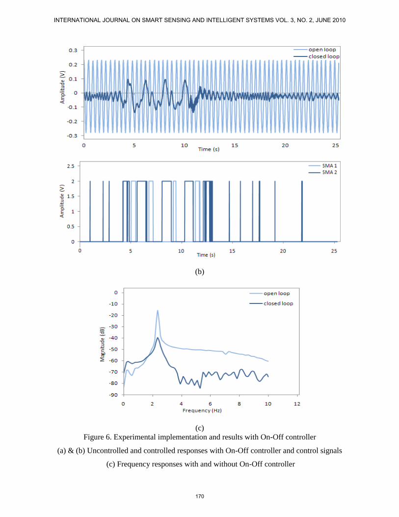
(b)
(c)
Figure 6 Experimental implementation and results with On-Off controller
(a) amp (b) Uncontrolled and controlled responses with On-Off controller and control signals
(c) Frequency responses with and without On-Off controller
INTERNATIONAL JOURNAL ON SMART SENSING AND INTELLIGENT SYSTEMS VOL 3 NO 2 JUNE 2010
170
The block diagram model shown in Figure 7 (a) is developed using LabVIEW for implementing
the PI controller in real time The open loop response closed loop response with proportional
control and the control signals are shown in Figure 7 (b) and the frequency responses of the
system acquired using DSO are shown in Figure 7 (c)
(a)
Data
acquisition
VIs
PID VI
used for PI
controller
Simulation
Loop
VI to save the
data in excel
sheets
Data
aquition
VIs
171
K Dhanalakshmi Aditya Avinash M Umapathy M Marimuthu Experimental Study on Vibration Control of Shape Memory Alloy Actuated Flexible Beam
(b)
(c)
Figure 7 Experimental implementation and results with P controller
(a) Real-time block diagram for PI controller in LabVIEW
(b) Uncontrolled and controlled responses with proportional controller and control signals
(c) Frequency responses with and without proportional controller
Similarly the open loop response closed loop response with proportional plus integral control
and the control signals are shown in Figure 8 (a) and its frequency response is shown in Figure 8
(b)
INTERNATIONAL JOURNAL ON SMART SENSING AND INTELLIGENT SYSTEMS VOL 3 NO 2 JUNE 2010
172
(a)
(b)
Figure 8 (a) Experimental results with proportional plus integral controller
(b) Frequency responses with and without PI controller
173
K Dhanalakshmi Aditya Avinash M Umapathy M Marimuthu Experimental Study on Vibration Control of Shape Memory Alloy Actuated Flexible Beam
VI CONCLUSIONS
The second order model of SMA actuated and piezoelectric sensed cantilever beam structure
excited at its first mode of resonant frequency has been identified using online ARX RLS system
identification approach The On-Off P and PI controllers have been designed and implemented
experimentally using LabVIEW 86 for the system model Controllers like the On-off which is
the simplest form of control proportional controller which attempts to perform better than the
On-Off type and the PI form of PID controller are designed simulated and implemented on the
system developed to demonstrate the vibration control strategies The closed loop responses
obtained through simulation with these control actions closely matches with that of the
experimental results for the system The closeness depends on suitable design and the selection of
control parameters For a sinusoidal excitation of 1 volt peak to peak an uncontrolled response of
0225 V peak to peak is obtained In the problem of first mode vibration control the following
reduction in amplitude of vibration is through simulation and experimentally
Control
Vibration reduction
Simulation Experiment
On-Off 80 78
Proportional 79 77
PI 82 80
The simulation and experimental results demonstrate the performance and practical simplicity of
the controller design and implementation using LabVIEW Experimental results show that the
closed loop response obtained with these control schemes exhibits substantial reduction in the
amplitude of flexural vibration at its first mode resonance The application programs made here
in LabVIEW use the software timing for timing related requirements But software timing is
affected by various factors like other processes run by operating system system hardware
specifications user interference etc Hence better vibration control can be achieved by
implementing hardware timing and by the use of real time systems like Compact RIO controller
[9] In this paper only basic controllers have been implemented which have various inherent
limitations hence advanced controllers can be implemented During the experimental study it has
been found that LabVIEW provides a very good platform to develop controllers and to
implement the designed controllers in real time very easily and efficiently
INTERNATIONAL JOURNAL ON SMART SENSING AND INTELLIGENT SYSTEMS VOL 3 NO 2 JUNE 2010
174
ACKNOWLEDGEMENT
The authors wish to acknowledge the funding from Indian Space Research Organization (ISRO)
RESPOND scheme for the support of this research
REFERENCES
[1] A Srinivasan and D McFarland ldquoSmart Structure Analysis and Designrdquo Cambridge
University Press 2001
[2] T Waram ldquoActuator design using Shape Memory Alloysrdquo Mondotronics Inc Canada
second edition 1993
[3] A Baz K Imam and J McCoy ldquoActive Vibration Control of Flexible Beams using Shape
Memory Actuatorsrdquo Journal of Sound and Vibration Vol 140 Issue 3 1990 pp 437 ndash 456
[4] Seung-Bok Choi and Chae-Cheon Cheong ldquoVibration control of a Flexible Beam using
Shape Memory Alloy Actuatorsrdquo Journal of Guidance Control and Dynamics Vol 19 Issue 5
1996 pp1178 ndash 1180
[5] Stefan Seelecke and Ingo Muller ldquoShape memory alloy actuators in smart structures
Modeling and Simulationrdquo ASME Vol 57 Issue 1 2004 pp 23 ndash 46
[6] J W Sohn Y M Han and S B Choi ldquoVibration and position tracking control of flexible
beam using SMA wire actuatorsrdquo Journal of Vibration and Control Vol 15 Issue 2 2009 pp
263-281
[7] Kyoung Kwan Ahn and Nguyen Bao Kha ldquoPredictive control for shape memory alloy
actuatorsrdquo Proceedings of the International Symposium on Electrical and Electronics
Engineering HCM City Vietnam 11-12 October 2005 pp 30-35
[8] D Ezhilarasi M Umapathy and BBandyopadhyay ldquoDesign and experimental evaluation of
piecewise output feedback control for structural vibration suppression using PZT patchesrdquo
Journal of Smart Materials and Structures Vol 15 2006 pp 1927 ndash 1938
[9] LabVIEW 86 User Manual NI LabVIEW Data Acquisition manual NI LabVIEW
Simulation and Design Toolkit Manual NI LabVIEW PID Control Toolkit Manual National
Instruments web portal (httpwwwnicom)
[10] Karl J Astrom and Tore Hagglund ldquoPID Controllers Theory Design and Tuningrdquo
International Society for Measurement and Control 2nd Sub edition 1995
175
K Dhanalakshmi Aditya Avinash M Umapathy M Marimuthu Experimental Study on Vibration Control of Shape Memory Alloy Actuated Flexible Beam

(b)
(c)
Figure 7 Experimental implementation and results with P controller
(a) Real-time block diagram for PI controller in LabVIEW
(b) Uncontrolled and controlled responses with proportional controller and control signals
(c) Frequency responses with and without proportional controller
Similarly the open loop response closed loop response with proportional plus integral control
and the control signals are shown in Figure 8 (a) and its frequency response is shown in Figure 8
(b)
INTERNATIONAL JOURNAL ON SMART SENSING AND INTELLIGENT SYSTEMS VOL 3 NO 2 JUNE 2010
172
(a)
(b)
Figure 8 (a) Experimental results with proportional plus integral controller
(b) Frequency responses with and without PI controller
173
K Dhanalakshmi Aditya Avinash M Umapathy M Marimuthu Experimental Study on Vibration Control of Shape Memory Alloy Actuated Flexible Beam
VI CONCLUSIONS
The second order model of SMA actuated and piezoelectric sensed cantilever beam structure
excited at its first mode of resonant frequency has been identified using online ARX RLS system
identification approach The On-Off P and PI controllers have been designed and implemented
experimentally using LabVIEW 86 for the system model Controllers like the On-off which is
the simplest form of control proportional controller which attempts to perform better than the
On-Off type and the PI form of PID controller are designed simulated and implemented on the
system developed to demonstrate the vibration control strategies The closed loop responses
obtained through simulation with these control actions closely matches with that of the
experimental results for the system The closeness depends on suitable design and the selection of
control parameters For a sinusoidal excitation of 1 volt peak to peak an uncontrolled response of
0225 V peak to peak is obtained In the problem of first mode vibration control the following
reduction in amplitude of vibration is through simulation and experimentally
Control
Vibration reduction
Simulation Experiment
On-Off 80 78
Proportional 79 77
PI 82 80
The simulation and experimental results demonstrate the performance and practical simplicity of
the controller design and implementation using LabVIEW Experimental results show that the
closed loop response obtained with these control schemes exhibits substantial reduction in the
amplitude of flexural vibration at its first mode resonance The application programs made here
in LabVIEW use the software timing for timing related requirements But software timing is
affected by various factors like other processes run by operating system system hardware
specifications user interference etc Hence better vibration control can be achieved by
implementing hardware timing and by the use of real time systems like Compact RIO controller
[9] In this paper only basic controllers have been implemented which have various inherent
limitations hence advanced controllers can be implemented During the experimental study it has
been found that LabVIEW provides a very good platform to develop controllers and to
implement the designed controllers in real time very easily and efficiently
INTERNATIONAL JOURNAL ON SMART SENSING AND INTELLIGENT SYSTEMS VOL 3 NO 2 JUNE 2010
174
ACKNOWLEDGEMENT
The authors wish to acknowledge the funding from Indian Space Research Organization (ISRO)
RESPOND scheme for the support of this research
REFERENCES
[1] A Srinivasan and D McFarland ldquoSmart Structure Analysis and Designrdquo Cambridge
University Press 2001
[2] T Waram ldquoActuator design using Shape Memory Alloysrdquo Mondotronics Inc Canada
second edition 1993
[3] A Baz K Imam and J McCoy ldquoActive Vibration Control of Flexible Beams using Shape
Memory Actuatorsrdquo Journal of Sound and Vibration Vol 140 Issue 3 1990 pp 437 ndash 456
[4] Seung-Bok Choi and Chae-Cheon Cheong ldquoVibration control of a Flexible Beam using
Shape Memory Alloy Actuatorsrdquo Journal of Guidance Control and Dynamics Vol 19 Issue 5
1996 pp1178 ndash 1180
[5] Stefan Seelecke and Ingo Muller ldquoShape memory alloy actuators in smart structures
Modeling and Simulationrdquo ASME Vol 57 Issue 1 2004 pp 23 ndash 46
[6] J W Sohn Y M Han and S B Choi ldquoVibration and position tracking control of flexible
beam using SMA wire actuatorsrdquo Journal of Vibration and Control Vol 15 Issue 2 2009 pp
263-281
[7] Kyoung Kwan Ahn and Nguyen Bao Kha ldquoPredictive control for shape memory alloy
actuatorsrdquo Proceedings of the International Symposium on Electrical and Electronics
Engineering HCM City Vietnam 11-12 October 2005 pp 30-35
[8] D Ezhilarasi M Umapathy and BBandyopadhyay ldquoDesign and experimental evaluation of
piecewise output feedback control for structural vibration suppression using PZT patchesrdquo
Journal of Smart Materials and Structures Vol 15 2006 pp 1927 ndash 1938
[9] LabVIEW 86 User Manual NI LabVIEW Data Acquisition manual NI LabVIEW
Simulation and Design Toolkit Manual NI LabVIEW PID Control Toolkit Manual National
Instruments web portal (httpwwwnicom)
[10] Karl J Astrom and Tore Hagglund ldquoPID Controllers Theory Design and Tuningrdquo
International Society for Measurement and Control 2nd Sub edition 1995
175
K Dhanalakshmi Aditya Avinash M Umapathy M Marimuthu Experimental Study on Vibration Control of Shape Memory Alloy Actuated Flexible Beam