experimenting with hybrid control r
TRANSCRIPT

Experimenting withHybrid Control
By Dimitrios Hristu-Varsakelis and Roger W. Brockett
Recently developed experimental and numeri-cal environments have helped breathe lifeinto the various control theories found intextbooks and have thereby greatly changedthe educational experience of students of au-tomatic control. Nonlinear balance beams,
inverted pendulums, and distributed parameter thermalsystems are now widely available for hands-on experimenta-tion. Many students react quite positively to this additional
dose of realism. Because the models selected for such ex-periments are usually accurately described by relativelysimple differential equations, the laboratory experience re-inforces both the textbook analysis and the value of numeri-cal simulation.
At the same time, there is a growing realization among ed-ucators and employers that students of automatic controlshould be encouraged to think of the subject in broaderterms. The systems approach should embrace communica-
82 IEEE Control Systems Magazine February 20020272-1708/02/$17.00©2002IEEE
Hristu-Varsakelis ([email protected]) is with the University of Maryland, 176 Glenn L. Martin Hall, College Park, MD 20742, U.S.A.Brockett is with Maxwell Dworkin Lab, Harvard University, Cambridge, MA 02138, U.S.A.
©E
YE
WIR
E.C
OM
tion requirements, signal processing, data logging, and soon, all the way up to and including the level of complexitysuggested by the phrase “enterprise control.” Designing acontrol experiment that is illustrative and instructional inthis broader sense presents several challenges beyondthose discussed above. The systems under considerationmust be very flexible. They should also re-flect the complexity of purpose and the pos-sibility of multimodal operation that oneexpects to find in complex systems. Ofcourse, the hardware must continue to be re-liable and relatively easy to understand at anintuitive level.
With these qualities in mind, we have as-sembled and extensively exercised an exper-imental hybrid control system for use in aninstructional/research laboratory at Har-vard. Our goal in this article is to describethe structure of the system and to present a sample of theexperiments that were facilitated by it.
An important feature of the facility we describe is that ituses several types of sensing modalities, including positionsensing, tactile sensing, and more conventional vision sens-ing. It can interact with objects of different complexity and issubject to communication constraints arising in a com-pletely natural and generic way. In constructing it, we haveused off-the-shelf components wherever possible and madechoices with an eye toward flexibility and reliability.
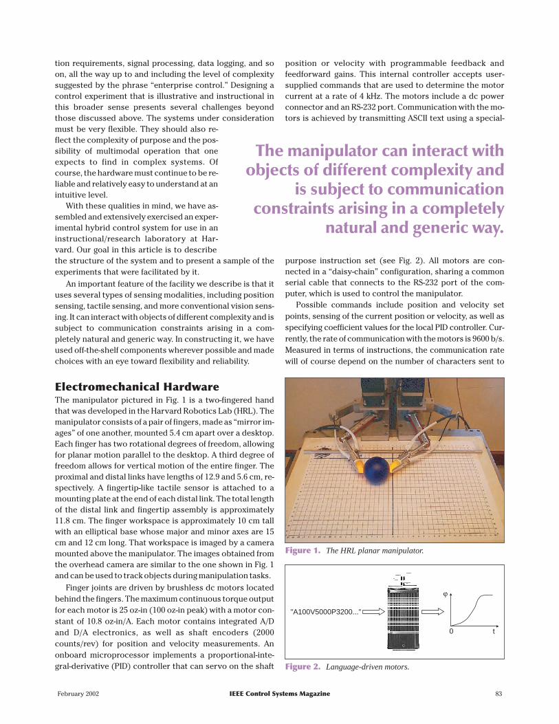
Electromechanical HardwareThe manipulator pictured in Fig. 1 is a two-fingered handthat was developed in the Harvard Robotics Lab (HRL). Themanipulator consists of a pair of fingers, made as “mirror im-ages” of one another, mounted 5.4 cm apart over a desktop.Each finger has two rotational degrees of freedom, allowingfor planar motion parallel to the desktop. A third degree offreedom allows for vertical motion of the entire finger. Theproximal and distal links have lengths of 12.9 and 5.6 cm, re-spectively. A fingertip-like tactile sensor is attached to amounting plate at the end of each distal link. The total lengthof the distal link and fingertip assembly is approximately11.8 cm. The finger workspace is approximately 10 cm tallwith an elliptical base whose major and minor axes are 15cm and 12 cm long. That workspace is imaged by a cameramounted above the manipulator. The images obtained fromthe overhead camera are similar to the one shown in Fig. 1and can be used to track objects during manipulation tasks.
Finger joints are driven by brushless dc motors locatedbehind the fingers. The maximum continuous torque outputfor each motor is 25 oz-in (100 oz-in peak) with a motor con-stant of 10.8 oz-in/A. Each motor contains integrated A/Dand D/A electronics, as well as shaft encoders (2000counts/rev) for position and velocity measurements. Anonboard microprocessor implements a proportional-inte-gral-derivative (PID) controller that can servo on the shaft
position or velocity with programmable feedback andfeedforward gains. This internal controller accepts user-supplied commands that are used to determine the motorcurrent at a rate of 4 kHz. The motors include a dc powerconnector and an RS-232 port. Communication with the mo-tors is achieved by transmitting ASCII text using a special-
purpose instruction set (see Fig. 2). All motors are con-nected in a “daisy-chain” configuration, sharing a commonserial cable that connects to the RS-232 port of the com-puter, which is used to control the manipulator.
Possible commands include position and velocity setpoints, sensing of the current position or velocity, as well asspecifying coefficient values for the local PID controller. Cur-rently, the rate of communication with the motors is 9600 b/s.Measured in terms of instructions, the communication ratewill of course depend on the number of characters sent to
February 2002 IEEE Control Systems Magazine 83
Figure 1. The HRL planar manipulator.
"A100V5000P3200..."
ϕ
0 t
Figure 2. Language-driven motors.
The manipulator can interact withobjects of different complexity and
is subject to communicationconstraints arising in a completely
natural and generic way.

each motor. If a position set point and measurement requestare transmitted to each of the four motors (a total of approxi-mately 60 characters), then the effective communication rateis approximately 20 Hz. Each motor is followed by 10/1 gearreduction. The distal link of each finger is connected to themotor’s gearbox with a chain drive, whereas the proximallink is connected directly to the gearbox. This results in a par-allel linkage mechanism for each finger, so that the rotationsof the distal and proximal links are decoupled.
The manipulator is controlled by a central digital com-puter, which coordinates data gathering and commands thefour actuators. By using joint angle, tactile sensing, and ob-ject position information, the manipulator can locate, grasp,and move objects on the desktop. The manipulator can beviewed as a hybrid system, combining continuous-timerigid-body dynamics and event-driven transitions, to be con-trolled with hybrid, language-driven actuators. These ideaswill be discussed in more detail as we proceed to describe theoperation of the manipulator and report on some of the re-search activities facilitated by our experimental setup.
A Vision-BasedDeformable Tactile SensorOver the last two decades, tactile sensing research has fo-cused on the development of technology and devices that
attempt to endow robots with some of the dexterity that hu-mans possess. Everyday experience, as well as analysis ofthe kinematics of manipulation and grasping [1], [2], sug-gest that contact forces and locations are the most impor-tant geometric parameters for manipulation, and it isprecisely those parameters that most tactile sensors are de-signed to measure.
The limitations of rigid fingertips in the precise and al-gorithmic study of manipulation have been discussed inmany works [3]-[5], some dating back more than a decade.One disadvantage of conventional tactile sensors is thatthey operate solely as force-sensing devices; that is, theymeasure the pressure distribution over their surface butprovide little or no information on possible deformationsof the surface itself. With few exceptions [6], [7], tactile ar-rays are typically mounted against a rigid backing and cov-ered with a thin rubber layer to provide friction. Rigiditylimits the degree to which such sensors can be used in ma-nipulation tasks [3]. Despite that fact, much of the work indexterous manipulation has continued to use the“point-contact” model for finger-object interactions. Infact, most of the existing tactile-sensing technologies, in-cluding tactile arrays ([8], [9], and others) and vi-sion-based tactile sensors [10]-[12], are not adaptable todeformable fingertips. The work in [4] and [13] exploreddifferent ways of constructing nonrigid fingertips; foam,rubber, powder, and gel were investigated. The gel-filledmembrane showed the best overall performance in termsof attenuation of impact forces, conformability, strain dis-sipation, and reality factors. The compliant fingertips de-scribed next most closely resemble the gel-filled fingertipused in [13].
Fig. 3 shows the deformable tactile sensor that has beendeveloped in the Harvard Robotics Lab as a result of a15-year collaborative effort. A more detailed description ofthe sensor and its operation can be found in [14]. The sen-sor consists of a metal housing and a roughly elliptical la-tex membrane that provides an area of contact. A clear,fluidlike gel fills the membrane, sealed off from the rest ofthe assembly by a transparent window. A grid of dots isdrawn at precisely computed locations on the inner sur-face of the membrane. A metal fingernail serves to providesupport for the membrane when the latter is being de-formed by contact. The fingertip is approximately 6.2 cmlong and has a diameter of 2 cm at its base. A schematic isshown in Fig. 4. The sensor’s metal housing holds a camerawith a diameter of 7.5 mm and a fiber-optic cable that illu-minates the interior surface of the membrane. The camerais connected to an image acquisition board, which cap-tures images of the grid of dots on the membrane. Typicalimages are shown in Fig. 5. The image size used was192 120× pixels. The sensor has mechanical properties thatare well suited to manipulation. In particular, the use of afluid-supported membrane [3] allows local deformations(caused by contact with an object) to be distributedthroughout the enclosed volume, because of the constant
84 IEEE Control Systems Magazine February 2002
Figure 3. The tactile sensor.
Housing
Lighting Membrane
Gel
Window
Camera
Figure 4. Tactile sensor schematic.

pressure of the fluid inside. This is in contrast to materialsthat obey Hooke’s law (i.e., rubber-covered rigid finger-tips) and allows the fingerpad to “wrap around” the objectlocally at a contact (see Fig. 6). Mechanically, the sensoracts much like a human fingertip and has been found to bevery effective in providing grasp stability.
An Inverse Problem:Membrane ReconstructionA particularly challenging problem involves the use of im-ages of the grid of dots drawn on the inner surface of themembrane to recover the three-dimensional shape of themembrane. This can be accomplished by a “reconstructionalgorithm,” which we will briefly describe here. Additionaldetails can be found in [15] and [14].
Consider the grid of dots drawn on the membrane. Theundeformed locations of the dots on the membrane areknown a priori. When the fingertip comes in contact withthe environment, the membrane deforms and the cameraobserves a change in the projections of the grid of dotsonto the image plane (as in Fig. 5(b)). A set of imaging op-erations (see Fig. 7) provides us with the two-dimensionalprojection of the deformations of the dots. Projective ge-ometry tells us that there exists an infinity of solutions forthe new three-dimensional coordinates of the dots. Underdeformation, the portion of the membrane that is not incontact will assume a shape that minimizes its elastic en-ergy. In addition, the volume enclosed by the membraneremains constant. These constraints, together with somegenericity assumptions on the grid of dots, are sufficientto obtain a solution for the three-dimensional coordinatesof the grid.
A reconstruction example is shown in Fig. 8, corre-sponding to a human fingertip lightly touching the mem-brane. The reconstruction algorithm uses images such asthe ones in Fig. 5 to produce a three-dimensional approxi-mation to the membrane surface in the form of a 13 13×mesh that corresponds to a 4-cm2 area on the fingerpad.
The coordinates of the grid are measured with respect to aEuclidean frame whose origin is at the center of thecharge-coupled device (CCD) array in the camera andwhose z-axis is perpendicular to that array. “Crossed”points represent the undeformed location of the grid. Theline segment through the grid is drawn through the cen-troid of the area of contact.
February 2002 IEEE Control Systems Magazine 85
(a) (b)
Figure 5. Camera view of membrane: (a) undeformed; (b) incontact with an object.
Figure 6. Grasping with a deformable fingertip.
Z
48
46
44
42
40
38
36
34
32
30−5 0 5
X
(a) (b) (c)
Figure 7. Fingertip operation: (a) image data of the displacement of the pattern of dots is used to interpolate a flow field, (b); the imageflow field, along with other constraints, enables reconstruction of the 3-D shape of the deformed membrane (c).

Tactile Sensor PerformanceBy computing the membrane displacement along the in-ward-pointing normal for each point on the grid, we canidentify the points that are part of a contact. Fig. 9(a) showstypical results obtained with this method when a pencil tipis pressed lightly against the fingerpad. The graph shows apeak forming around the area of contact from which we candetermine that the pencil was pressed about 1 mm into themembrane. The area of contact included 14 grid points withtheir centroid at (−4.5 mm, −3.7 mm, 22.2 mm) measured in acoordinate frame located at the end of the distal link. The
same method can be used to simultaneously detect multipleareas of contact (Fig. 9(b)).
Typically, the reconstructed grid is used to estimatethe maximum deformation and contact coordinates. Theminimum inward displacement that can be detected is 0.5mm. For small deformations of the membrane, the sensorcan localize contact with a maximum error of 1.9 mm,equal to one-half of the distance between neighboringdots on the membrane surface. The availability of an ap-proximation to the fingertip surface allows one to esti-mate the local curvature of objects that come into contactwith the sensor.
The reconstruction algorithm involves a significantamount of computation and image processing. On a dual 400-MHz Pentium PC, the maximum rate of performing this recon-struction is 15 Hz using a 5 5× grid of dots on the membraneand a13 13× interpolated grid to approximate the fingerpadsurface. This rate is lower than what can be achieved withtraditional tactile sensors; however, the deformable sensorprovides a much richer description of a contact.
Additional experimental results involving our tactile sen-sor can be found in [5]. Results on the use of the sensor inmanipulation experiments are presented in [16]. Other ap-plications being explored include the miniaturization of thesensor and its use as a laparoscopic device in minimally in-vasive surgery.
Visual TrackingTogether with tactile information, knowledge of the object’sposition is important during manipulation. An overheadcamera captures images of the manipulator’s workspace.These images are processed to detect and track objects inthat workspace. Tracking software was developed to com-pute the position and orientation of the object relative to aninertial frame fixed on the desktop. To make it easier for thetracking algorithm to locate objects, a pair of black dots ismounted against a light background on the object. Alterna-tively, using simple image thresholding, the tracking algo-rithm can locate any dark-colored object against the lightbackground of the desktop. Images obtained from the over-head camera are similar to that of Fig. 1. In this case, only po-sition information is computed. The overhead camera
provides 192 120× images that corre-spond to an area of 36 cm × 28 cm onthe desktop. Consequently, each pixelimages a 1.9-mm × 2.3-mm area.
Object tracking is made more effi-cient by using an estimate of the ob-ject’s velocity—computed from pasttracking data—to avoid searching theentire scene. If p v ak k k, , ∈R 2 are theposition, velocity, and acceleration ofthe object, then the estimate �pk + 1 ofthe next (expected) object position iscomputed according to
86 IEEE Control Systems Magazine February 2002
40
35
30
25
20
15
10
5
0
Z
Y X
10
5
0
−5−10 −10
0
10
Undeformed versus Deformed Surface
Figure 8. Tactile sensing example.
1.41.2
10.80.60.40.2
010
50
−5−10 −10
010
−55
Z [mm]
1.41.2
10.80.60.40.2
010
50
−5−10 −10
010
−55
Y [mm]X [mm]
(b)(a)
Figure 9. Detection of (a) single and (b) multiple contacts.

�p p v t a t
vp p
t
av v
t
k k k k
kk k
kk k
+
++
++
= + +
=−
=−
12
11
11
12
∆ ∆
∆
∆ (1)
and the tracking algorithm searches a small region around�pk + 1 to find the object and determine pk + 1. The maximumtracking rate is 60 Hz on a dual 400-MHz PC, currently limitedby the maximum rate at which the camera can capture videoframes. Fig. 10 shows the position data ob-tained during a manipulation task superim-posed on a snapshot of the manipulatorduring the task.
Learning to ManipulateHumans use their hands in many everydaytasks with remarkable dexterity and areable to integrate visual and tactile signalsto manipulate various objects with preci-sion, speed, and efficiency. The develop-ment of robotic hands with similar capabil-ities is aimed at producing mechanical andcontrol systems that will be able to per-form many of the tasks that are beyond the capabilities ofconventional robot grippers. However, robotic fingersadd significantly to the complexity of a manipulator, bothin mechanical design and in control and coordination.Multifingered manipulation is difficult in part because itinvolves rolling contact between the object and fingersurfaces. This introduces a nonholonomic constraint intothe kinematics of the object-hand system. As a result, theplanning of finger motions depends on the geometric evo-lution of the object-finger contact(s) [1], [2], [17], [18].The contact evolution is itself dependent on the kine-matic configuration of the hand, the object trajectory, andmost important, the object’s geometry, which is oftenonly approximately known.
Learning can be an effective approach to manipulationbecause it allows the handling of a large class of objects us-ing the same algorithm, rather than having to specify modelparameters for every object that one would like to manipu-late. In addition, precise surface models may be difficult toobtain for all but the simplest of object geometries. A con-trol system that learns would make it possible for the user toabstract from the particulars of system components and in-stead focus on its desired behavior only, while the internaldetails of system dynamics, constraints, and so on, remain“hidden.” Toward that end, consider the following proto-type problem.
• Problem Statement 1: Given an object and a feasibletrajectory that is parametrized by time, find the actua-tor commands that result in the object following thattrajectory as closely as possible.
In this context, a “feasible” trajectory is one that does notrequire the fingers to travel outside their workspace orthrough any singular kinematic configurations.
To solve instances of Problem 1, we choose to decom-pose it into an equivalent pair of problems:
• Problem Statement 2: Given an object and a desiredfeasible trajectory, find the joint trajectories that cor-respond to the object following the desired trajectory.
• Problem Statement 3: Find the actuator commandsthat result in the joints tracking a set of desired trajec-tories “as closely as possible.”
Kinematic Exploration of anObject TrajectoryThe first step toward solving an instance of Problem 1 in-volves “lifting” the object trajectory to the space of joint an-gles. We accomplish this by performing a “kinematicexploration” of the desired object trajectory, as well as bysampling the evolution of the model-dependent effects ofrolling and fingertip compliance along the trajectory. Theuse of feedback and learning while exploring the kinematicsof a particular manipulation task allows us to avoidmodel-based methods [2] that may be computationally ex-pensive and difficult to implement.
Before we proceed, it is useful to review the kinematics ofthe finger/object system. Consider a set of k fingers, each withm degrees of freedom, making contact with an object. Letθ τ, ∈ ⋅Rm k be the vector of the manipulator’s joint angles and
February 2002 IEEE Control Systems Magazine 87
Figure 10. Tracking an object on the desktop.
The actuators used to drive themanipulator are language-drivendevices. This feature allows us to
explore questions of motionplanning and optimal description of a
motion task in the given language.

torques. Also, let v ∈R 6 be the instantaneous object velocityand f ∈R 6 be the total wrench acting about an inertial framefixed on the object. The kinematics of rolling contact can besummarized in the following well-known set of equations [1]:
G v J
J w
f Gw
T
T
===
( )�
( )
,
θ θτ θ
(2)
where J is the manipulator Jacobian and G is the so-calledgrasp matrix. The quantity w denotes the vector of forcesacting at the object/finger contacts. The grasp matrix is de-termined by the coordinates of the object/finger contacts,which are also necessary to specify J . Of course, the evolu-tion of (2) during a manipulation task depends on the geom-etry of the object and fingertips. This dependence is madeexplicit quite elegantly in [2]. We note that the stability of agrasping configuration can be determined from the rank ofG. In addition, the last equality in (2) can be used to selectthe internal forces applied to the object by exerting finger-tip forces that are in the nullspace of G.
The following algorithm (similar to that in [19]) was usedto learn the kinematics of manipulating an unknown objectalong a desired locus of points:
0) Sample spatially the desired object trajectory, using afinite number of set points.
1) Determine a desired incremental motion for the objecttoward the next object trajectory set point.
2) Sense the position/orientation of the object, the coor-dinates of each fingertip/object contact, the force ateach contact, and all joint angles.
3) Compute the fingertip forces necessary to maintain asufficiently tight grasp on the object. If an adjustmentto the grasp is necessary, apply it and repeat step 1.
4) Solve the hand-object kinematics of (2) for the incre-mental change in joint angles based on the desiredchange in object position/orientation.
5) Apply the change in joint angles to the fingers.6) If the desired object set point has been reached, store
the desired joint positions and velocities (computedfrom (2) for a given desired object velocity) for this setpoint. Otherwise repeat from step 2.
7) Repeat from step 1 until the object has attained all tra-jectory set points.
Fig. 11 shows a typical trajectory obtained using theabove algorithm. For this task, a 2-in-diameter spherical ob-ject was used. The apparent “noise” in the actual trajectoryis due to the resolution limit of the overhead camera thatwas used to measure the position of the object.
Software OrganizationIn the present setting, software development required a sig-nificant amount of time, taking approximately 50% of theperson-years invested in this project. For this reason, wethink it is appropriate to describe how the software was or-ganized and to discuss its possible reuse.
Over the last decade, there has emerged an engineeringapproach to the linguistic description of motion controltasks [20]-[23]. The actuators used to drive the HRL manipu-lator are particularly suited for the study of motion descrip-tion languages because they are language-driven devices.This feature allows us to explore questions of motion plan-ning and optimal description of a motion task in the givenlanguage. Using the actuators’ instruction set, together withbasic sensing operations, we have implemented a set of con-trol primitives (akin to the “atoms” and “behaviors” of MDL[24]). These are building blocks in terms of which graspingand manipulation tasks can be described. Our goal was toimplement the beginnings of a motion language for use withmultifingered manipulators. This language should contain,at its highest levels, primitives for grasping and manipula-tion tasks, so that the user needs to specify little or no infor-mation about the object other than its desired trajectory.
There is, of course, a substantial amount of literature onsoftware organization, with no shortage of works emphasiz-ing the power and conceptual advantages of thinking interms of objects, classes, and reusable modules. We referthe reader to standard references on the subject (e.g., [25]).When it comes to the control of electromechanical systems,however, standard object-oriented methods will take on asomewhat special form because the software must interactwith one-of-a-kind hardware and instruction sets. In addi-tion, there are few precedents that could dictate how soft-ware should be organized. We chose to organize softwaremodules according to their interaction with the hardwareand with the outside world.
Software/Hardware InteractionThe use of off-the-shelf hardware implies that the instruc-tion sets are essentially fixed. In our case, there is a givencommand set for the actuators and another for the image ac-quisition board. These sets are treated as assembly code,
88 IEEE Control Systems Magazine February 2002
Y [c
m]
7
6
5
4
3
2
−4 −2 0 2 4
X [cm]
Solid: ActualDash: Desired
Figure 11. Kinematic exploration of a “figure-8" path.

and we designed low-level routines that interface to them.The following is a partial list of the available hard-ware-dependent primitives.
• Sensing: The controller receives joint, tactile, or ob-ject position data by transmitting a request to the ap-propriate sensor. Joint angles are measured byquerying the corresponding motors. Polling a tactilesensor provides a three-dimensionalvector for the contact location (i.e.,the centroid of the area of contact),the maximum deformation depth, aswell as a vector for the surface normalat the point of maximum deformation.
• Actuation: The controller can transmita joint position or velocity commandto a specific motor. The PID controllerresiding in the motor uses the com-mand as a set point and regulates mo-tor current. The controller can modifythe parameters of the PID loop and canspecify upper limits for the angular velocity and accel-eration of the motor.
• Feedforward Control: The controller transmits a pre-defined sequence of control inputs to the motors (inreal time).
Hardware-Independent PrimitivesWe would like motion description languages to have asmuch portability as traditional C++. One could argue thatcurrently there is almost no portability for motion controlprograms. On the other hand, the HRL manipulator hasgiven us a chance to see what such a software environmentmight be like. The following high-level primitives abstractfrom the specifics of the hardware and provide the basicfunctionality necessary for manipulation.
We note that each of the software modules described inthis work must be supplemented by algorithms that are cor-rect in detail. This constitutes an important but tedious pro-cess that is beyond the scope of this article. In the interest ofspace, we omit many of the details; however, we do want toavoid the gross oversimplification sometimes found in AItexts and wish to call attention to the fact that behind eachof the following primitives is a certain amount of mathemati-cal analysis. Primitives are arranged according to the physi-cal complexity of the corresponding task:
• Find Object: Involves image processing, segmentation,and template-based search. This primitive initiates aroutine that obtains an image of the desktop from theoverhead camera and searches that image for an ob-ject. Currently, an object is detected either by its con-trast to the light-colored desktop or by a pair offiducial dots mounted on its surface.
• Grasp Object: The mathematics here have to do withfinger kinematics and Jacobians, as well as the graspmatrix (2) and its rank [17]. After an object has been
located, the controller moves the fingertips closer tothe object using inverse kinematics. Usually, no infor-mation is available on the object’s geometry; there-fore, the controller proceeds by moving the fingertipsslowly toward the known center of the object whilethe tactile sensors are monitored for signs of contact.When contact has occurred, tactile data is used to
check for grasp stability. This is done by examiningthe singular values of the grasp matrix. Finally, the fin-gertips are moved along the surface normal at thecontact(s) to tighten the grasp as desired. The finger-tip forces necessary to apply a desired internal forceto the object can be computed by solving an optimiza-tion problem whose data include a basis for the nullspace of the grasp matrix [1].
• Catch Object: This primitive uses the manipulator’s in-verse kinematics and Jacobian, together with a simpledifference equation (1) that estimates the location of amoving object in the images acquired from the over-head camera. The controller tracks a moving objecton the desktop (e.g., a rolling ball) and guides the fin-gers to follow the object at a fixed prespecified dis-tance on either side. When the object’s velocitydecreases below a specified threshold, the fingers aremoved quickly toward the object until contact occurs.
• Point-to-Point Manipulation: Enables the manipulatorto move an object from one equilibrium configurationto another. Once the object has been securelygrasped, the controller uses joint, tactile, and visualfeedback, together with the kinematics of the manipu-lator, to compute the incremental joint motions re-quired to bring about a desired incremental objectmotion by means of (2) (see also [17]-[19]).
• Teleoperation: The user provides a desired positionfor the object using a pointing device (such as a com-puter mouse) while the controller uses grasping andpoint-to-point manipulation primitives to move theobject according to the user’s commands.
• Kinematic Exploration: The analysis here makes use ofthe manipulator’s Jacobian and kinematics (2) in a feed-back control loop. Given a desired object trajectory (foran object in the manipulator’s workspace), the control-
February 2002 IEEE Control Systems Magazine 89
Lack of time to communicate is animportant constraint compared tolack of computational power. The
HRL manipulator was used to exploreaspects of this “coupling” between
control and communication.

ler uses low-level and point-to-point manipulation primi-tives to move the object to each of a sequence ofconfigurations, all lying on the desired trajectory.
A Note on Software ArchitectureWe do not expect the reader to be interested in coding de-tails (which are available from the authors); however, we dowant to give a general idea of the architecture of our soft-ware, as well as the manner in which primitives interact witheach other. Following the paradigm of MDL [23], [24], [26],each hardware-independent primitive was implemented asa feedback loop that can be interrupted based on sensordata (for example, a vision sensor indicates that an objecthas been located and the manipulator should now move tograsp it). Once a primitive is interrupted, another begins torun. This procedure takes place on a computer (called the“control processor”) that transmits control inputs to the ac-tuators and decides which primitive to run at a given time.
Due to the complexity of our sensor suite, a significantamount of preprocessing must take place before the rawdata (e.g., pixel values) are converted to information thatcan be used by a primitive (e.g., coordinates of an ob-ject-fingertip contact). For this reason, all code that imple-ments sensing operations is executed on a dedicatedsecond processor (called the “sensing processor”). Thesensing processor maintains a polling table with the ad-dresses of some or all of the available sensing routines. Dur-ing each feedback cycle, these routines are executed andtheir output(s) are returned to the control processor. Ofcourse, each primitive might have different requirementswith respect to which sensors must be polled (e.g., tactilesensors only versus tactile sensors and overhead camera)or how the raw data should be processed (e.g., measuringlocal curvature at a contact versus simply detecting con-tact). For this reason, our implementation allows for a primi-tive to dynamically interrupt the sensing processor and
reset its polling schedule to include a new subset of sensors.Such an action causes the sensing processor to begin run-ning a new set of routines and posting the resulting databack to the control processor for use by the primitive thatmade the request. This arrangement makes the software ef-ficient (because a sensor does not consume CPU time ifthere is no demand for its output) and enforces the separa-tion between the hardware-independent algorithm and thedata gathering necessary to drive that algorithm.
As we have indicated, feedback loops running on the con-trol processor are closed by data arriving from the sensingprocessor. Of course, the highest frequency at which sensordata can be generated (and thus the highest rate at which afeedback loop can run) depends on the sensing modalitiesand amount of preprocessing that have been requested bythe corresponding control primitive. In addition, becausethe sensing processor does not run a real-time operatingsystem, there is a slight variability in the time intervals be-tween data arrivals at the control processor. The resulting“jitter” in the feedback loop does not seem to cause a prob-lem in the operating domains we have explored.
Software/Communication InteractionUntil recently, it had been common to “decouple” the com-munication aspects from the underlying dynamics of a con-trol system, as this simplified the analysis and generallyworked well for classical models. In the past few years, how-ever, advances in electronics, communications, and networktechnologies have enabled the development of large-scale,complex systems. This has led to the need to reexaminesome of the fundamental assumptions involving the effects ofcommunication on control. Smart structures, communica-tion networks, robots, and formations of autonomous vehi-cles are all examples of systems that incorporate anunprecedented number of components, all of which must op-erate in a coordinated manner. These systems are distributed
in the sense that their sensors, actua-tors, and computing elements commu-nicate via a shared medium, be it aradio frequency, a computer bus, orpins on a VLSI device. Restrictions onaccess to this medium often have a pro-found effect on the performance of theoverall system, pointing to the neces-sity for analytical tools that bridge com-munication and control.
As the complexity of a system in-creases, simultaneous communicationamong components becomes an unre-alistic assumption. Instead, sensorsand actuators must “share the atten-tion” of the controller. Lack of time tocommunicate is therefore an impor-tant constraint compared to lack ofcomputational power. The HRL manip-
90 IEEE Control Systems Magazine February 2002
Camera
4 kHz
Motor 1 Link
20 Hz
CPU
Motor 4 Link
Tactile/Joint Sensing
Object Position
Figure 12. Low-level control architecture.

ulator was used to explore aspects ofthis “coupling” between control andcommunication.
The manipulator uses actuatorsthat share the computer’s serial portso that the computer can communi-cate with only one motor at a time.Therefore, the coordination of actua-tion and sensing operations requires that the controllerchoose which motors and sensors to exchange informationwith at a particular time. Fig. 12 illustrates the control loopsand communication constraints that govern the operationof the manipulator. The communication constraints govern-ing the operation of the manipulator become importantwhen one requires the manipulator to follow a desired tra-jectory in real time. The controller cannot supply continu-ous inputs to the actuators, nor can it update all actuatorssimultaneously. In the following, we introduce a simplemodel that can be used to analyze this situation and thatcaptures characteristics of a rather general class of hybridcontrol systems.
A Model for LimitedCommunication ControlConsider a continuous-time, linear time-invariant (LTI) sys-tem that is controlled by a digital computer (Fig. 13).
• The controller cannot provide continuous inputs tothe LTI system; instead, commands are sent to the sys-tem every ∆ units of time via a zero-order hold.
• The dimension of the communication bus (b) that car-ries controller-generated inputs may be smaller thanthe input dimension of the LTI plant (m). As a result,the controller must choose which of the input signalsto update at every cycle.
We are interested in control tasks of finite duration; therefore,we consider controller-generated sequences of fixed length N .To fix notation, let �b N( ) denote sequences of length N whoseelements are in R b . The plant is defined by the triple( , , )B A C m n n n n p∈ × ×× × ×R R R , with G s C sI A B( ) ( )= − −1 .Finally, L Tp
2 0[ , ] denotes the space of square-integrable func-tions with finite support, taking values in R p .
The controller can select which input is to be updated ata particular time. This leads to the idea of a “communicationsequence” [27], which can be understood as the order of op-erations for the switch(es) connecting the controller to thevarious parts of the system. We will use the notation
{ }σ σ σ σ σ= − ∈( ( ), ( ),..., ( )) : ( ) { , }0 1 1 0 1N i m
to represent a communication sequence. The vectors σ( )i ofa communication sequence σ are to be interpreted as indica-tors of which of the elements of the system input v t( ) are tobe updated by the controller at t i= ∆, i N= −0 1, ,… . Becauseonlyb inputs can be communicated at one time, we must im-pose a feasibility condition, namely, that Σ j j i bσ ( ) ≤ for
i N= −0 1,..., . It is worth noting that the definition of a com-munication sequence allows us to quantify the amount of“attention” the controller pays to each input and output of acomputer-controlled system.
This model for computer-controlled systems has beenused to understand optimal control problems involving out-put tracking [28] and stabilization [29] in the presence ofcommunication constraints. Here we discuss some of theideas involving the input-output characteristics of com-puter-controlled systems.
Input-Output BehaviorWe ignore for the moment any constraints having to do withthe size of the communication bus (i.e., all m inputs can beupdated at once) and consider the resulting sampled-datasystem as a linear, time-varying map that takes sequences tocontinuous-time outputs: Λ ∆∆( , , ) ( ): ( ) [ , ]G N
m pt N L N� → 2 0 .This map is completely determined by the parameters ofthe underlying LTI plant, the controller’s sampling period,and the duration of the task:
y t t u t k u kG s Nk
N
( ) ( ) ( ) ( )( ( ), , )= = −=
−
∑Λ ∆∆ ∆φ0
1
,
where
φ = ≥
<
∫ −
∆
∆
( ).
( , ) ( )
t Ce Bd t
t
t A t
00
0 0
min τ τ
Now, fix a communication sequence σ according to whichinputs are to be transmitted. The multiplexing action of σcan be expressed as a linear operator M( )σ
M N Nb m: ( ) ( )� �→ .
The operator M is determined by the elements of σ. In fact, ifwe identify elements of �b N( ) with vectors in RN b⋅ , then Mcan be written as an Nm Nb× matrix with binary entries. Thekey to constructing M is to notice that consecutive elements( ′ ′ +σ σ( ), ( )k k 1 for some k) of a sequence ′ ∈σ Range( )M dif-fer in at mostb places (as dictated by σ( )k ). The closed-formexpression for M is rather cumbersome and will not begiven here (see [28]). To summarize, for a fixed communica-tion sequence, the overall input-output map is given by
y Mu= Λ ,
February 2002 IEEE Control Systems Magazine 91
0 ∆
u N( )∈ b��m( )N
ZOHy Cx=
0 N∆
x Ax Bv= +.
y L N[0, ]∈ ∆2p
Figure 13. A computer-controlled system.
where we have suppressed the dependence of Λ and M onthe system parameters.
An Invertibility ExperimentWe now proceed to apply our analysis of computer-con-trolled systems to a class of problems involving real-timetrajectory tracking.
Suppose that we would like to manipulate an object alongthe (planar) real-time trajectory:
x t t
y t t td
d
( ) . ( )
( ) . . sin( ), [ , ]
== + ∈
4 2
4 5 1 7 2 0 1
cos
s. (3)
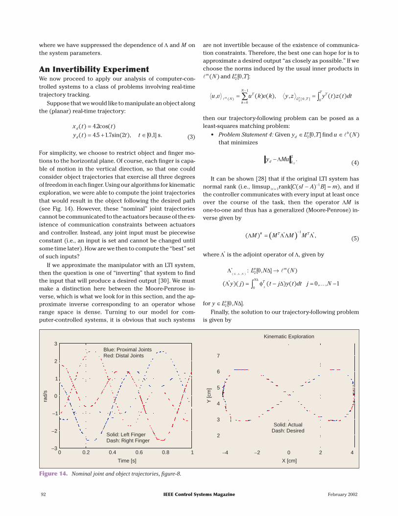
For simplicity, we choose to restrict object and finger mo-tions to the horizontal plane. Of course, each finger is capa-ble of motion in the vertical direction, so that one couldconsider object trajectories that exercise all three degreesof freedom in each finger. Using our algorithms for kinematicexploration, we were able to compute the joint trajectoriesthat would result in the object following the desired path(see Fig. 14). However, these “nominal” joint trajectoriescannot be communicated to the actuators because of the ex-istence of communication constraints between actuatorsand controller. Instead, any joint input must be piecewiseconstant (i.e., an input is set and cannot be changed untilsome time later). How are we then to compute the “best” setof such inputs?
If we approximate the manipulator with an LTI system,then the question is one of “inverting” that system to findthe input that will produce a desired output [30]. We mustmake a distinction here between the Moore-Penrose in-verse, which is what we look for in this section, and the ap-proximate inverse corresponding to an operator whoserange space is dense. Turning to our model for com-puter-controlled systems, it is obvious that such systems
are not invertible because of the existence of communica-tion constraints. Therefore, the best one can hope for is toapproximate a desired output “as closely as possible.” If wechoose the norms induced by the usual inner products in�m N( ) and L Tp
2 0[ , ]:
u v u k v k y z y t z tm pNT
k
N
L TT
T, ( ) ( ), , ( ) ( )
( ) [ , ]�= =
=
−
∑ ∫0
1
0 02dt
then our trajectory-following problem can be posed as aleast-squares matching problem:
• Problem Statement 4: Given y L Tdp∈ 2 0[ , ] find u Nb∈� ( )
that minimizes
y Mud L−Λ
2
2 .(4)
It can be shown [28] that if the original LTI system hasnormal rank (i.e., limsup rank| | [ ( ) ]s C sI A B m=
−− =11 ), and if
the controller communicates with every input at least onceover the course of the task, then the operator ΛM isone-to-one and thus has a generalized (Moore-Penrose) in-verse given by
( )( )# * *Λ ΛΛ ΛM M M MT T=−1
, (5)
where Λ* is the adjoint operator of Λ, given by
Λ ∆
Λ ∆
∆
∆
∗
∆
( , , ): [ , ] ( )
( )( ) ( ) (*
G NL N N
y j t j y t
p m
TN
2
0
0 →
= −∫
�
φ ) , ,dt j N= −0 1…
for y L Np∈ 2 0[ , ]∆ .Finally, the solution to our trajectory-following problem
is given by
92 IEEE Control Systems Magazine February 2002
3
2
1
0
−1
−2
−30 0.2 0.4 0.6 0.8 1
Time [s]
Solid: Left FingerDash: Right Finger
Blue: Proximal JointsRed: Distal Joints
rad/
s
7
6
5
4
3
2
Y [c
m]
Solid: ActualDash: Desired
X [cm]
Kinematic Exploration
−4 −2 0 2 4
Figure 14. Nominal joint and object trajectories, figure-8.

( )u M M M y yT Td ic*
* *( )= −−
ΛΛ Λ1
,
where yic is the effect of the initial conditions of G s( ).Equation (5) can be considered an analog of the
well-known formula for the left pseudo-inverse of an opera-tor K n m:R R→ , with m n> , rank( )K n= :
( )K K K KT T# =−1
.
Trajectory-Following ExperimentsWe modeled the manipulator as a four-input LTI com-puter-controlled system with a communication bus of di-mension 1. Using kinematic exploration, we obtained thenominal joint trajectories required for the object to followthe path given by (3) (shown in Fig. 14). A communicationsequence was selected, and the generalized inverse of (5)was used to compute the optimal input sequence u* (a totalof 20 samples to be sent to the motor per second). That se-quence was transmitted to the actuators, and the actual ob-ject trajectory was recorded. Finally, the L2 tracking error,y Mud −Λ *, was evaluated.
Uniform AttentionWe selected a communication sequence corresponding to“uniform attention”
σ = ( , , , , , , )e e e e e e1 2 3 4 1 4… ,
where ei denotes the standard basis vector in �4 . In this set-ting, the finger joints are labeled as follows: 1—left proximal,2—left distal, 3—right proximal, and 4—right distal. Fig. 15shows the input signals applied to the actuators and the result-ing object trajectory. There is good agreement between the de-sired and actual curves. The L2 tracking error (4) was 5.5.
AveragingTo obtain a basis for comparison, we computed a sequenceof control inputs by averaging the nominal (but infeasible)actuator inputs of Fig. 14. For example, if a control samplewere to be sent at t tk= and then at t tk= + 1, then setu u t dt t tk t
t
k kk
k= −+
∫ +( ) / ( )1
1 . Fig. 16 shows the input/outputpair corresponding to that approach. Tracking performancewas quite poor, with an L2 error of 12.1.
Nonuniform AttentionThe figure-8 tracking experiment was performed again, thistime using a communication sequence that devotes 10%,35%, 15%, and 40% to inputs 1, 2, 3, and 4, respectively:
σ = ( , , , , , , , , ,
, , , , , ,
e e e e e e e e e
e e e e e e e3 4 1 2 4 4 2 4 1
2 4 2 3 4 2 4 , , , , ),e e e e2 3 4 2
again using the standard basis vectors in�4 to specify whichinput gets updated at a particular time. Notice that distaljoints (inputs 2 and 4) are updated more frequently thanproximal joints. We arrived at this choice of communicationsequence by observing the desired joint trajectories (in Fig.14). For each time interval of length ∆ = 0 05. s, we allocatedcommunication cycles using as a guide the amount of rota-tion required by each joint over that interval. Tracking perfor-mance was slightly improved compared to what wasachieved with uniform attention. The L2 error was 3.2 (Fig. 17).
Conclusions and New VistasWe have described an experimental facility designed tostudy aspects of multimodal intelligent control and re-ported on some of the related research activities. The pur-pose of the manipulator is to provide a reliable, versatilecontrol system that will be useful both as an instructionalaid and as a research tool. As the field of intelligent control
February 2002 IEEE Control Systems Magazine 93
0 0.2 0.4 0.6 0.8 1
Time [s]
rad/
s
7
6
5
4
3
2
Y [c
m]
X [cm]
Object Trajectory
−4 −2 0 2 41
2
1.5
1
0.5
0
−0.5
−1
−1.5
Red: u1Blue: u2
Green: u3Teal: u4
Blue: ActualRed: Desired
Figure 15. Optimal inputs (uniform attention) and resulting object trajectory.

gains maturity, new issues are emerging related to our un-derstanding of larger, multicomponent systems and to theinteractions among control, communication, complexity,networks, and signal processing. Our goal in developing ahybrid system of this type was to create a “system of sys-tems” that captures such interactions and in which severalsensing and actuation modalities have to be brought to-gether into the control decisions. The manipulator’s ro-bustness is reflected in the large number of graduate andundergraduate students who have used the system overthe past 15 years. Although the manipulator has under-gone several refinements over time, the use of off-the-shelfcomponents whenever possible has contributed to its longlife and upgradability. Some of the research efforts forwhich the manipulator has proved useful involved me-
chanical design, computer vision, real-time programming,limited communication control, robotic manipulation, andtactile sensing.
Current plans for improving the mechanical characteris-tics of the manipulator include replacing the transmissionchain and gears with a cable drive to decrease joint compli-ance and backlash. Estimating object shape from overheadimages could prove valuable in planning effective grasps. Inaddition, the rich set of data provided by the manipulator’sfingertips could be used to sense slip or in combination withoverhead images for shape estimation. More broadly, it isimportant to understand how sensors and actuators might“best” share the attention of the (centralized) controller.The manipulator allows us to explore problems of this type,which are of interest to a broad spectrum of researchers. In
94 IEEE Control Systems Magazine February 2002
0 0.2 0.4 0.6 0.8 1
Time [s]
rad/
s
7
6
5
4
3
2
Y [c
m]
X [cm]
Object Trajectory
−4 −2 0 2 41
2
1.5
1
0.5
0
−0.5
−1
−1.5
Red: u1Blue: u2
Green: u3Teal: u4
Blue: ActualRed: Desired
−2
2.5
Figure 16. “Average” inputs (uniform attention) and resulting object trajectory.
0 0.2 0.4 0.6 0.8 1
Time [s]
rad/
s
7
6
5
4
3
2
Y [c
m]
X [cm]
Object Trajectory
−4 −2 0 2 4
2
1.5
1
0.5
0
−0.5
−1
−1.5
Red: u1Blue: u2
Green: u3Teal: u4
Blue: ActualRed: Desired
Figure 17. Optimal inputs (nonuniform attention).

fact, issues related to attention, including the interaction ofcontrol and communication, are of particular significance tomodern engineering systems where the presence of a net-work or of a distributed topology is becoming increasinglycommon. We believe that the experimental system pre-sented in this work, together with others like it, can contrib-ute to the ongoing investigation of these questions, as wellas to the education of future engineers. To date, the HRL ma-nipulator has helped shape five doctoral theses and 15 un-dergraduate research projects at Harvard, under thedirection of the second author. It has influenced our teach-ing on a wide variety of topics, as suggested by the refer-ences. We expect that the manipulator will continue toevolve, and we hope that other researchers will find it a use-ful paradigm for intelligent control.
AcknowledgmentThis work was funded by the following grants: Army DAAG55 97 0114, NSF EEC 94 02384, and Army DAAL 03-92-G 0115.
References[1] J. Kerr and B. Roth, “Analysis of multifingered hands,” Int. J. Robot. Res.,vol. 4, no. 4, pp. 3-17, Winter 1986.[2] D.J. Montana, “The kinematics of contact and grasp,” Int. J. Robot. Res., vol.7, no. 3, pp. 17-32, 1988.[3] R.W. Brockett, “Robotic hand with rheological surfaces,” in Proc. 1985 IEEEInt. Conf. Robotics and Automation, 1985, pp. 942-946.[4] K.B. Shimoga and A.A. Goldenberg, “Soft robotic fingertips, part I: A com-parison of construction materials,” Int. J. Robot. Res., vol. 15, no. 4, pp.320-334, 1996.[5] D. Hristu, N.J. Ferrier, and R.W. Brockett, “The performance of a deform-able-membrane tactile sensor: Basic results on geometrically defined tasks,”in Proc. 2000 IEEE Int. Conf. Robotics and Automation, Apr. 2000, pp. 508-513.[6] E.J. Nicolson and R.S. Fearing, “Sensing capabilities of linear elastic cylin-drical fingers,” in Proc. RSJ/IEEE Int. Conf. Intelligent Robots and Systems, 1993,vol. 1, pp. 178-85.[7] R.A. Russell, “Compliant-skin tactile sensor,” in Proc. 1987 IEEE Int. Conf.Robotics and Automation, June 1987, pp. 2221-233.[8] W.D. Hillis, “Active touch sensing,” Int. J. Robot. Res., vol. 1, no. 2, pp. 33-44,1982.[9] R.S. Fearing, “Tactile sensing mechanisms,” Int. J. Robot. Res., vol. 9, no. 3,pp. 3-23, 1990.[10] J. Rebman and K.A. Morris, “A tactile sensor with electrooptictransduction,” in Robot Tactile Sensors, A. Pugh, Ed., vol. 2. Berlin: IFS Publica-tions, Springer-Verlag, 1986, pp. 145-155.[11] S. Begej, “Planar and finger-shaped optical tactile sensors for robotic ma-nipulation,” IEEE Trans. Robot. Automat., vol. 4, no. 5, pp. 472-484, 1988.[12] H. Maekawa, K. Tanie, K. Komoriya, M. Kaneko, C. Horiguchi, and T.Sugawara, “Development of a finger-shaped tactile sensor and its evaluationby active touch,” in Proc.1992 IEEE Int. Conf. Robotics and Automation, June1992, pp. 2221-233.[13] K.B. Shimoga and A.A. Goldenberg, “Soft robotic fingertips, part {II}:Modeling and impedance regulation,” Int. J. Robot. Res., vol. 15, no. 4, pp.335-350, 1996.[14] N. Ferrier, K. Morgansen, and D. Hristu, “Implementation of membraneshape reconstruction,” Harvard Robotics Lab, Harvard Univ., Tech. Rep. 97-1,1997.[15] N.J. Ferrier and R.W. Brockett, “Reconstructing the shape of a deform-able membrane from image data,” Int. J. Robot. Res., vol. 19, pp. 1-22, 2000.[16] D. Hristu, “Optimal control with limited communication,” Ph.D.dissertation, Harvard Univ., Division of Engineering and Applied Sciences,1999.
[17] J. Kerr, “An analysis of multifingered hands,” Ph.D. dissertation, StanfordUniv., Dept. Mechanical Engineering, 1984.[18] D.J. Montana, “Tactile sensing and the kinematics of contact,” Ph.D. dis-sertation, Harvard Univ., Division of Applied Sciences, 1986.[19] H. Maekawa, K. Tanie, and K. Komoriya, “Tactile sensor based manipula-tion of an unknown object by a multifingered hand with rolling contact,” inIEEE Int. Conf. Robotics and Automation, June 1995, pp. 743-750.[20] R.W. Brockett, “On the computer control of movement,” in Proc. 1988IEEE Conf. Robotics and Automation, April 1988, pp. 534-540.[21] R.W. Brockett, “Formal languages for motion description and map mak-ing,” in Robotics, J. Baillieul, D.P. Martin, R.W. Brockett, and B.R. Donald, Eds.American Mathematical Society, 1990, pp. 181-93.[22] R.M. Murray, D.C. Deno, K.S.J. Pister, and S.S. Sastry, “Control primitivesfor robot systems,” IEEE Trans. Syst., Man, Cybernet., vol. 22, no. 1, pp. 183-193,1992.[23] V. Manikonda, P.S. Krishnaprasad, and J. Hendler, “Languages, behaviors,hybrid architectures and motion control,” in Mathematical Control Theory,J.C. Willems and J. Baillieul, Eds. New York: Springer-Verlag, 1998, pp. 199-226.[24] R.W. Brockett, “Language driven hybrid systems,” in Proc. 33rd IEEE Conf.Decision and Control, 1994, pp. 4210-4214.[25] E. Gamma, R. Helm, R. Johnson, J. Vlissides, and G. Booch, Design Pat-terns: Elements of Reusable Object-Oriented Software. Reading, MA: Addi-son-Wesley, 1995.[26] D. Hristu, “The MDLe engine: A software tool for hybrid motion control,”Institute for Systems Res., University of Maryland, Tech. Rep., 2001.[27] R.W. Brockett, “Stabilization of motor networks,” in Proc. 34th IEEE Conf.Decision and Control, 1995, pp. 1484-1488.[28] D. Hristu, “Generalized inverses for finite-horizon tracking,” in Proc. 38thIEEE Conf. Decision and Control, 1999, vol. 2, pp. 1397-402.[29] D. Hristu and K. Morgansen, “Limited communication control,” Syst.Contr. Lett., vol. 37, no. 4, pp. 193-205, 1999.[30] R.W. Brockett, “The invertibility of dynamic systems with application tocontrol,” Ph.D. dissertation, Case Western Reserve Univ., 1964.
Dimitrios Hristu-Varsakelis is an Assistant Professor in theDepartment of Mechanical Engineering and an Affiliate mem-ber of the Institute for Systems Research at the University ofMaryland, College Park. He received the B.S. degree in electri-cal engineering and computer science from the University ofCalifornia, Berkeley, in 1992 and the M.S. degree in electricalengineering from Rensselaer Polytechnic Institute in 1994.From 1994-1999, he was a graduate student in the Division ofEngineering and Applied Sciences at Harvard University andreceived the M.S. degree in applied mathematics and thePh.D. in engineering sciences. His research interests includecontrol with limited communication, hybrid systems, and in-telligent machines. He is a member of the IEEE and a recipientof the 1999 Eliahu Jury award from the Division of Engi-neering and Applied Sciences, Harvard University.
Roger W. Brockett is An Wang Professor of Electrical Engi-neering and Computer Science in the Division of Applied Sci-ences at Harvard University. He has worked on variousaspects of control theory and applications, including recentwork in hybrid systems involving elements of computing aswell as control. He received the American Automatic Con-trol Council’s Richard Bellman Control Heritage Award andthe IEEE’s Control Systems Science and Engineering Award.He is a Fellow of the IEEE and a member of the National Acad-emy of Engineering.
February 2002 IEEE Control Systems Magazine 95