explorer - welcome to the thorn lighting website — new ... · pdf filehelps to guide...
TRANSCRIPT

ExplorerComprehensive testing for emergency lighting

When an incident occurs and power is lost, emergency lighting helps to guide people safely and calmly from the building while enabling the emergency services to do their work
In a modern building environment, light is taken for granted. People trust it as they go about their lives. It promotes comfort, security and efficiency.

�
Emergency lighting testing – Integrated safety provides comfort of use, security and efficiency
Normal Use
The lighting scheme with integrated emergency luminaires is designed for optimal performance, efficiency and comfort. The emergency luminaire versions blend into the overall scene.
Thorn Explorer technology brings intelligence to the emergency lighting system and enables owners and operators to ensure that their emergency lighting system is fully tested and ready to operate at optimum performance.
A comprehensive, integrated emergency lighting package, Explorer, provides the peace of mind and full confidence of regulatory compliance. This fully automatic, economic testing system will satisfy the needs of the most demanding of authorities and produce comprehensive documentation, at the ‘touch of a button’.
PEC Explorer reflects Thorn’s intentions to deliver ‘Performance’, ‘Efficiency’ and ‘Comfort’ (PEC) in all of its products. The PEC programme concentrates on delivering ‘quality’ in a lighting installation.
Performance: The emergency luminaires in the system provide emergency lighting and signage in accordance with EN18�8
Efficiency: The system automatically tests the luminaires in accordance with EN620�4
Comfort: Peace of mind that no manual testing is required and that the test records are automatically stored for two years. Luminaires are automatically identified when repair is required.
MenloSoft SR
Emergency Operation
Emergency luminaires are designed to illuminate anti-panic areas and escape routes to the correct lighting levels and the exit signage to indicate the way out.

4
Explorer SelfTest Explorer Project Explorer Vision
Automatic testing: Yes Yes Yes
EN620�4 compliant: Yes Yes Yes
Fault indication on luminaire: Locally via LED Centrally logged on Control Panel Centrally logged on PC and Control Panels
Fault reports generated: Manually Printed or via SMS text Printed or e-mailed
Max. no of luminaires per system: 1 256 (with extenders) 5000
Communication cabling required: No Yes Yes / Computer network
Programmable: No Yes Yes
Addressable: No Yes Yes
Typical applications: Small areas or refurbishment projects where additional cabling is impractical. For example: offices, small shopping centres, restaurants, public houses, hotels and guest houses, medical centres
Small and medium sized projects where visual inspection of luminaires is impractical or undesirable. For example: universities, schools and colleges, museums, shopping centres, offices, industrial facilities
Large projects where programmable testing of large numbers of luminaires is required. For example: hospitals, universities, museums, airports, supermarkets and hypermarkets, industrial facilities
SelfTestMany challenges – which option is best?
Automated and cost effective testing of Emergency Lighting: Explorer SelfTest, Explorer Project and Explorer Vision
Just like fire protection systems, emergency lighting is potentially life saving but worthless and hazardous if the equipment is not properly maintained. As a consequence there are increasingly stringent legal requirements to regularly inspect, test and maintain emergency lighting in workplaces or public buildings.
Explorer, the Thorn Lighting Emergency Test product range, provides automated testing of emergency luminaires that is fully compliant with European Standards. This offers complete peace of mind and safety without the need for costly and time-consuming manual testing by a competent person, which is required for the most basic of conventional self-contained emergency luminaires.
Your emergency lighting needs to be regularly tested to check that it is working properly (and to conform with the requirements of the regulations). A functional test (where the luminaire changes over to emergency operation) must be performed every month. A full duration test is required annually, to confirm that the battery has sufficient energy to operate the luminaire in the emergency mode for � hours.
The Explorer testing system automatically checks functional testing weekly and duration testing annually, in accordance with the requirements of EN620�4.
Explorer has been designed with three options to suit varying requirements and budgets. Consult the quick comparison table below to help decide which option is best for you.
Summary of benefits• Cost effective compliance
with emergency lighting testing regulations
• Explorer SelfTest performs the testing automatically for you – only requiring you to walk around the building once per month and record that all is ok (or any failures)
• Explorer Project and Vision performs all of the testing and records the results
Project
Vision
121
2
3
4
56
7
8
9
10
11
5
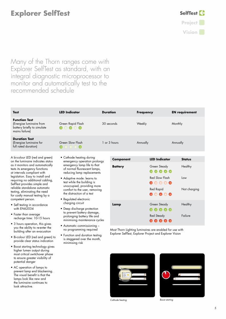
Component LED Indicator Status
Battery Green Steady Healthy
Red Slow Flash Low
Red Rapid Not charging
Lamp Green Steady Healthy
Red Steady Failure
Test LED Indicator Duration Frequency EN requirement
Function Test(Energise luminaire from battery briefly to simulate mains failure)
Green Rapid Flash �0 seconds Weekly Monthly
Duration Test(Energise luminaire for full rated duration)
Green Slow Flash 1 or � hours Annually Annually
Cathode heating Boost starting
A bi-colour LED (red and green) on the luminaire indicates status as it monitors and automatically tests its emergency functions at intervals compliant with legislation. Easy to install and requiring no additional cabling, SelfTest provides simple and reliable standalone automatic testing, eliminating the need for costly manual testing by a competent person.
• Self testing in accordance with EN620�4
• Faster than average recharge time: 10-15 hours
• � hours operation, this gives you the ability to re-enter the building after an evacuation
• Bi-colour LED (red and green) to provide clear status indication
• Boost starting technology gives higher lumen output during most critical switchover phase to ensure greater visibility of potential danger
• AC operation of lamps to prevent lamp end blackening. The visual benefit is that the lamps look like new and the luminaire continues to look attractive.
SelfTest
Project
Vision
Explorer SelfTest
Many of the Thorn ranges come with Explorer SelfTest as standard, with an integral diagnostic microprocessor to monitor and automatically test to the recommended schedule
• Cathode heating during emergency operation prolongs emergency lamp life to that of normal fluorescent lamps, reducing lamp replacements
• Adaptive mode: learns to test while the building is unoccupied, providing more comfort to the user, removing the distraction of a test
• Regulated electronic charging circuit
• Deep discharge protection to prevent battery damage, prolonging battery life and minimising maintenance cycles
• Automatic commissioning – no programming required
• Function and duration testing is staggered over the month, minimising risk
Most Thorn Lighting luminaires are enabled for use with Explorer SelfTest, Explorer Project and Explorer Vision

6
XP128 Controller
DALI
Emergency operation
Explorer ProjectUp to 128 emergency luminaires
Intelligent emergency lighting rises to the challenge
Explorer Project is the perfect emergency lighting monitoring system for medium-size installations where low overheads and full compliance are essential. At the heart of the automatic monitoring system is the XP128 controller which provides quick and easy visual supervision over all emergency luminaires without special training.

L N
Gnd24V XPPSU
PE N L A-D
1
A-D
2
B-D
1
B-D
2
TxD
RxD
Gnd
K11
K12
K14
K21
K22
K24
K31
K32
K34
Gnd
RxD
TxD
Gnd XPGSMExplorer Project GSM Module
24V
�
SelfTest
Project
Vision
• The XP128 controller supervises 128 luminaires over two channels of up to 64 luminaires each
• Touch screen for easy programming
• Can be expanded to 256 luminaires via XPX64 modules (see pages 8 and 9)
• Infra-red port can up-load reports to hand-held printers
• Volt-free contacts enable signalling to remote locations indication or interface to a BMS (building management system)
• GSM module (XPGSM) can report faults via text message to mobile phones and also supports ‘one person commissioning’
The luminaires contain a module that communicates to the XP128 controller which signals over wires to tell them to perform their weekly functional tests and annual duration tests. To maintain integrity, they are asked to do these tests in groups at periods of minimum risk, in accordance with the requirements.
Bus wiring to luminaires and XPX64 expander modules 300m max – use 1.5mm2 twisted pair, equivalent to Belden 9411
Mains
Mains
max. 250m/1.5mm2/ max. 64 Luminaires
Three volt free contacts to signal system status
max. 24V A
C/D
C m
ax.2A
K11-K14 NO K11-K12 NCK21-K24 NO K21-K22 NCK�1-K�4 NO K�1-K�2 NCNO: nomally open (SchlleBer)NC: normally closed (Offner)
Mains Mains Mains Mains MainsMains
max. 250m/1.5mm2/ max. 64 Luminaires
Mains Mains Mains Mains MainsMains
Remote aerial – supplied with 5m lead
PE N L A-D
1
A-D
2
B-D
1
B-D
2
Tx
Rx
Gnd
K11
K12
K14
K21
K22
K24
K31
K32
K34
*) *) *) *) *) *)
*) *) *) *) *) *)
*) *) *) *) *) *)
*) *) *) *) *) *)
*) *) *) *)
out D
1
out D
2
in D
1
N L
in D
2
XPX64
out D
1
out D
2
in D
1
N L
in D
2
XPX64
out D
1
out D
2
in D
1
N L
in D
2
XPX64
*)
*)
*)
...................................
...........................
...........................
...........................
.............................
...............................................................................................................................
......
......
......
......
...
......
......
......
......
......
......
......
......
......
......
......
......
......
......
......
......
......
......
......
......
......
......
......
......
.....
......
......
......
......
......
......
....
......
......
..
................
..........................
...................
XP128 Controller
GSM Module
XP Extender
8
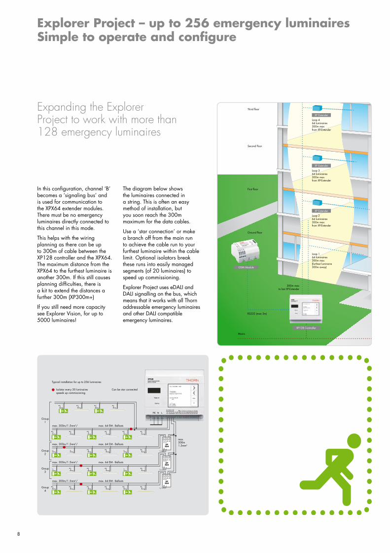
Explorer Project – up to 256 emergency luminaires Simple to operate and configure
Expanding the Explorer Project to work with more than 128 emergency luminaires
In this configuration, channel ‘B’ becomes a ‘signaling bus’ and is used for communication to the XPX64 extender modules. There must be no emergency luminaires directly connected to this channel in this mode.
This helps with the wiring planning as there can be up to �00m of cable between the XP128 controller and the XPX64. The maximum distance from the XPX64 to the furthest luminaire is another �00m. If this still causes planning difficulties, there is a kit to extend the distances a further �00m (XP�00m+)
If you still need more capacity see Explorer Vision, for up to 5000 luminaires!
Third floor
Second floor
First floor
�00m max to last XP-Extender
RS2�2 (max �m)
Mains
Loop 264 luminaires�00m max from XP-Extender
Loop �64 luminaires�00m max from XP-Extender
Loop 464 luminaires�00m max from XP-Extender
GSM Module
XP Extender
XP Extender
XP Extender
XP128 Controller
Loop 164 luminaires�00m max(furthest luminaire �00m away)
Ground floor
The diagram below shows the luminaires connected in a string. This is often an easy method of installation, but you soon reach the �00m maximum for the data cables.
Use a ‘star connection’ or make a branch off from the main run to achieve the cable run to your furthest luminaire within the cable limit. Optional isolators break these runs into easily managed segments (of 20 luminaires) to speed up commissioning.
Explorer Project uses eDALI and DALI signalling on the bus, which means that it works with all Thorn addressable emergency luminaires and other DALI compatible emergency luminaires.
Typical installation for up to 256 luminaires
Isolator every 20 luminaires speeds up commissioning
Can be star connected
max. �00m 1.5mm2
max. �00m/1.5mm2/ max. 64 EM - Ballasts
Group 1
Group 2
Group �
Group 4
max. �00m/1.5mm2/ max. 64 EM - Ballasts
max. �00m/1.5mm2/ max. 64 EM - Ballasts
max. �00m/1.5mm2/ max. 64 EM - Ballasts

LuminairesAddress CallibrationCheck
Luminaire address group 1 (10 luminaires)
Next >
Floor 1, north entry
auto-search . . .
location:
logical
address:
Cancel
assign
< Previous
1
Test
all groups similar
Start function test
start function test now ...
Funct. test Duration test Relay
also see test book
every Thur, Fri16 : 00 : 00at oclock.
?
RelaybuzzerAssignments AssStatus
Rela
y 1
OK
Factory settings
Lamp fault
Battery fault
Comm. problem
Test error, time out
Func. test running
Rela
y 2
Rela
y 3
Buzzer
GS
M
?
Tue, 10.02.2004 16:52
info
?
Explorer Project XP128
Last test result:OK
Quick Menu
info
?
BLOCK system . . .
Start function test . . .
Start duration test . . .
�
SelfTest
Project
Vision
1. Touch screen Used to operate the system. The screens are intuitively arranged for easy use. This first screen gives access to the quick menu or other pages to input data, display test results and so on.
2 and 3. Testing Automatic tests normally run once a week. When a manual or duration test is required, it can be selected here. The block feature is used when selected luminaires (in sensitive areas such as operating theatres) should only be tested manually.
4. Addressing Luminaires are addressed on site after installation. No special programming is required, making the process quick and reliable, with no logistical problems.
5. Assigning relays and GSM Relays can be selected to operate according to the type of test or fault. GSM operations are also configured here.
Summary of benefits• Performs all of the testing and
records the results
• Cost effective compliance with emergency lighting testing regulations
• Test results stored for 2 years
• Explorer Project is for up to 256 emergency luminaires
• XP300m+ gives additional wiring distance
1.
2.
3.
4.
5.

10
* Not supplied
SelfTest
Project
Vision
Explorer VisionUp to 500 luminaires
For up to 500 emergency luminaires, choose the Explorer Vision XV500.
This computer operates monitoring software, that ‘talks’ to the XP128 controllers over a standard computer network cable (up to 100m) to the Nport2 interface. This interface converts the signals from ‘TCP-IP’ to RS232 so that the XP128 controller can understand them. The screen (not provided) shows the status of the emergency luminaires.
If you need a longer distance between the XV500 and the Explorer Project XP128 controllers, use your computer network to perform the connections – see configuration diagram overleaf. You would connect the XV500 in place of the XV5000. Now you can monitor the XV500 from another computer on your local area network (using the software provided). Note: if your building layout needs you to have more than 1m between the XP128 controllers just use an extra Nport2 – see diagram overleaf.
Summary of benefits• Medium system
• Up to 500 emergency luminaires
• Direct connection up to 100m
• Can connect XV500 to your computer network and monitor it from another of your own network computers
Explorer Vision satisfies the needs of larger installations requiring more than 256 emergency luminaires
XV500
Cross-over cable up to 100m
XPX64 Max 3
64max Luminaires
64max Luminaires
64max Luminaires
64max Luminaires
RS232 1m max
300m max1.5mm2 unscreened twisted
pair equivalent to Belden �411
Nport2
XPX64 Max 3
64max Luminaires
64max Luminaires
64max Luminaires
64max Luminaires
300m max1.5mm2 unscreened twisted
pair equivalent to Belden �411
RS232 1m max

11
XV5000 / XV5000D Computer
* Not suppliedUse your computer network to link multiple Explorer Project controllers together to support as many as 5000 emergency luminaires over a 1000m distance.
A larger computer operates the monitoring software, which ‘talks’ to the XP128s over a standard computer network cable via a Nport2 interface. This interface converts the signals from ‘TCP-IP’ to RS232 so that the XP128 can understand them. The screen (not provided) shows the status of the emergency luminaires.
Summary of benefits• Large system
• Up to 5000 luminaires
• Uses computer network for communication
• Use another PC on your computer network to view status of your emergency lighting
• Distances up to 1000m over your computer network
Explorer Vision connects into your computer network and monitors your emergency lighting system
SelfTest
Project
Vision
XV5000
Ethernet (shielded twisted pair cable) CAT5 cable (Limit 100m)
RS232 1m max
Nport2
XPX64 Max 3
64max Luminaires
64max Luminaires
64max Luminaires
64max Luminaires
300m max1.5mm2 unscreened twisted
pair equivalent to Belden �411
Ethernet (shielded twisted pair cable) CAT5 cable (Limit 100m)
Ethernet (shielded twisted pair cable) CAT5 cable (Limit 100m)
Fibre-optic link (Limit 1000m)
Max. 5 Hubs serial from computer or after switch
Ethernet (shielded twisted pair cable) CAT5 cable (Limit 100m)
RS232 1m max
Nport2
RS232 1m max
Nport2
Ethernet (shielded twisted pair cable) CAT5 cable (Limit 100m)
HUB
HUB
SWITCH
SWITCH
For the more challenging application...Up to 5000 luminaires

12
1. 2. 3.
4. 5. 6.
SelfTest
Project
Vision
Explorer Vision – How it works
Monitoring your emergency lighting system
1. Explorer Vision links XP128 controllers together and monitors the status of the emergency luminaires.
2. It is easy to navigate around the installation. Each Explorer Project XP128 is shown along with its four groups (of up to 64 luminaires) e.g. Main building ground floor, west wing. Just click onto an area to get to the luminaires you want to access.
3. Click on the luminaire to get its details.
4. Click on the group and the luminaires are displayed.
5. Faults are indicated by the red luminaire and details are displayed. You can easily monitor the Explorer Vision computer, from another computer connected to the network using the software provided on the disc. Note, the software licence only permits one user, so if the computer is being accessed locally e.g. for maintenance purposes, it is not possible to operate it from a remote station, until the local work has been completed. All functions that are available on the Explorer Project controller XP128 can be accessed from the Explorer Vision computer. It operates like a ‘virtual touch screen’.
6. Here the testing regime for the XP128 is being programmed from the Explorer Vision controller.
Summary of benefits• Checks your emergency
lighting remotely
• All Explorer Project functions can be accessed using the keyboard of the XV500/XV5000/XV5000D
• See your emergency lighting networked system from one screen
Explorer VisionVersion 3.7 (Build 3.7.1.1)
Company: A.N. OtherBuilding: Enterprise HouseLicense code: LMC-0520-5861-2813-7613-7267-0190License limit: local serverReference number: 255975920
Time limit: none
THORN Lighting
www.thornlight.com

13
MenloSoft SR
Voyager Elite SXVoyager Elite Voyager Elite XR
AquaForce Diffusalux II
Quattro T line
SelfTest
Project
Vision
Typical luminaires available as Explorer SelfTest or to work with Explorer Project/Explorer Vision

14
Explorer Project Components SelfTest
Project
Vision
Contact your local sales engineer if you require commissioning for your Explorer Project
XP128 22154297
Controller
High quality controller for monitoring, testing and fault logging for up to 128 emergency or exit sign luminaries. Can be expanded to operate up to 256 using XPX64 extenders. 2 year rolling memory. Din rail mounted.
XPX64 22154301
Extender (adds 64 luminaires)
Module (used on Channel B) extends the Explorer Project Controller capacity by a further 64 luminaire addresses.For up to 1�2 use 2 modules1�3 – 256 use 3 modules. Din rail mounted.
EXPISO 96218105
Isolator
Splits circuits and reduces commissioning time.
XP300m+ 22154567
300m extra wiring
Kit comprises a XV Repeater and DALI Power Supply. Allows for additional 300m wiring from the XPX64 or XP128 controller. Din rail mounted.
XPGSM 22154298
GSM Module
GSM Module facilitating ‘one man’ commissioning of emergency lighting systems using a mobile phone. Also sends SMS messages to maintainer on discovering a fault. SIM card not supplied. Din rail mounted.
XPPSU 22154300
GSM power supply
Required to power the GSM module. Din rail mounted.
XPPRI 22154299
Infra red hand held printer
Used for printing test reports from the log file of the XP128 controller. Power supply by battery, data transfer via infrared interface.

15
SelfTest
Project
Vision
Explorer Vision Components
XV5000 22154562
Computer (Analogue) (Up to 5000 luminaires)
Computer with visualisation package for graphic display and monitoring of up to 5000 emergency or escape sign luminaires. Analogue modem for remote access over telephone line. Complete with mouse and keyboard. Additional software for another PC to monitor if networked (single user licence enabled).
XV5000D 22154569
Computer (Digital) (Up to 5000 luminaires)
Computer with visualisation package for graphic display and monitoring of up to 5000 emergency or escape sign luminaires. Digital modem for remote access over broadband connection. Complete with mouse and keyboard. Additional software for another PC to monitor if networked (single user licence enabled).
XVCOM 22154566
Commissioning for Explorer Vision
XV500 22154561
Computer (Up to 500 luminaires)
Computer with visualisation package for graphic display and monitoring of up to 500 emergency or escape sign luminaires. Complete with mouse and keyboard and 230/24V power supply. Additional software for another PC to monitor if networked (single user licence enabled).
Nport2 72052223
Network Interface
Converts Explorer Vision signals to Explorer Project format (TCP-IP to RS232). Normally one per XP128 controller. (1m max RS232 to XP128) Can be used for up to 2 Explorer Project XP128 controllers.
SC Kabelsatz 72052839 Nport
Pack of 2 cables (each 1m long to connect between the Nport2 and the RS2323 port on the XP128 Controller

Lighting people and places
Thorn Lighting LimitedUKSilver Screens, Elstree Way, Borehamwood, Hertfordshire, WD6 1FE
UK Sales desk - Orders/Stock EnquiriesTel: 08701 610 610 Fax: 08701 610 611Project Enquiries:Tel: 08701 610 710Fax: 08701 610 711
Ireland320 Harold’s Cross Road, Dublin 6W Tel: (353) 1 4�22 877Fax: (353) 1 4�22 724E-mail: [email protected]
Outdoor LightingSilver Screens, Elstree Way, Borehamwood, Hertfordshire, WD6 1FETel: 020 8732 �82�Fax: 020 8732 �825E-mail: [email protected]
Spare PartsTel: 01�1 301 3131Fax: 01�1 301 3038E-mail: [email protected]
Technical SupportTel: 0870 600 8111Fax: 01�1 301 3�07E-mail: [email protected]
Brochureline Answering ServiceBrochures on specific products/rangesTel: 020 8732 �8�8 Fax: 020 8732 �8��E-mail: [email protected]
International Sales Silver Screens, Elstree Way, Borehamwood, Hertfordshire, WD6 1FETel: (44) 20 8732 1�15Fax: (44) 20 8732 1�11E-mail: [email protected]
Thorn Lighting Ltd DubaiAl Shoala Building, Office 301,Block E, PO Box 1200, Deira, Dubai, UAETel: (�71) 4 2�40181Fax: (�71) 4 2�48838E-mail: [email protected]
Thorn Gulf LLCAl Shoala Building, Office 301/2,Block E, PO Box 1200, Deira, Dubai, UAETel: (�71) 4 2�48�38Fax: (�71) 4 2�48838E-mail: [email protected]
Other Offices in:Australia, Austria, China, Czech Republic, Denmark, France, Hong Kong, Italy, New Zealand, Norway, Poland, Russia, Singapore, Sweden and UAE
www.thornlighting.co.uk
Thorn Lighting is constantly developing and improving its products. All descriptions, illustrations, drawings and specifications in this publication present only general particulars and shall not form part of any contract. The right is reserved to change specifications without prior notification or public announcement. All goods supplied by the company are supplied subject to the company’s General Conditions of Sale, a copy of which is available on request. All measurements are in millimetres and weights in kilograms unless otherwise stated.
Publication No: 396 (GB) Publication Date: 02/07
ISO �001:2000Reg: 2�16/0
Manufacturing & DistributionMember of The Lighting
Industry Federation