exploring freecadrknet.pl/student/2013_2014/pg/mat_pom/freecad.pdf · exploring freecad freecad is...
TRANSCRIPT

Exploring FreeCAD
FreeCAD is a 3D CAD/CAE parametric modeling application. It is primarily made for mechanical design, but also serves all other uses where you need to model 3D objects with precision and controlover modeling history.
1. The 3D view, showing the contents of your document
2. The tree view, which shows the hierarchy and construction history of all the objects in your document
3. The properties editor, which allows you to view and modify properties of the selected object(s)
4. The output window, which is where FreeCAD prints messages, warnings and errors
5. The python console, where all the commands executed by FreeCAD are printed, and where you can enter python code
6. The workbench selector, where you select the active workbench
The main concept behind the FreeCAD interface is that it is separated into workbenches. A workbench is a collection of tools suited for a specific task, such as working with meshes, or drawing 2D objects, or constrained sketches. You can switch the current workbench with the workbench selector (6). You can customize the tools included in each workbench, add tools from other workbenches or even self-created tools, that we call macros. There is also a generic workbench which gathers the most commonly used tools from other workbenches, called the complete workbench.

Workbenches
FreeCAD, like many modern design applications such as Revit or CATIA, is based on the concept of Workbench. A workbench can be considered as a set of tools specially grouped for a certain task. In a traditional furniture workshop, you would have a work table for the person who works with wood, another one for the one who works with metal pieces, and maybe a third one for the guy who mounts all the pieces together.
In FreeCAD, the same concept applies. Tools are grouped into workbenches according to the tasks they are related to.
The following workbenches are available:
• The Part Design Workbench for building Part shapes from sketches• The Draft Workbench for doing basic 2D CAD drafting• The Mesh Workbench for working with triangulated meshes• The Part Workbench for working with CAD parts• The Image Workbench for working with bitmap images• The Raytracing Workbench for working with ray-tracing (rendering)• The Drawing workbench for displaying your 3D work on a 2D sheet• The Robot Workbench for studying robot movements• The Sketcher Workbench for working with geometry-constrained sketches• The Arch Workbench for working with architectural elements• The OpenSCAD Workbench for interoperability with OpenSCAD and repairing CSG
model history• The Assembly Workbench for working with multiple shapes, multiple documents,
multiple files, multiple relationships...• The Fem Workbench for Pre- and Post-processing FEM studies• The Ship Workbench FreeCAD-Ship works over Ship entities, that must be created on
top of provided geometry.• The Plot Workbench The Plot module allows to edit and save output plots created from
other modules and tools.
New workbenches are in development, stay tuned!
When you switch from one workbench to another, the tools available on the interface change. Toolbars, command bars and eventually other parts of the interface switch to the new workbench, but the contents of your scene doesn't change. You could, for example, start drawing 2D shapes withthe Draft Workbench, then work further on them with the Part Workbench.
Note that sometimes a Workbench is referred to as a Module. However, Workbenches and Modules are different entities. A Module is any extension of FreeCAD, while a Workbench is a special GUI configuration that groups some toolbars and menus. Usually every Module contains its own Workbench, hence the cross-use of the name.
Document structure
A FreeCAD document contains all the objects of your scene. It can contain groups, and objects made with any workbench. You can therefore switch between workbenches, and still work on the same document. The document is what gets saved to disk when you save your work. You can also open several documents at the same time in FreeCAD, and open several views of the same document.
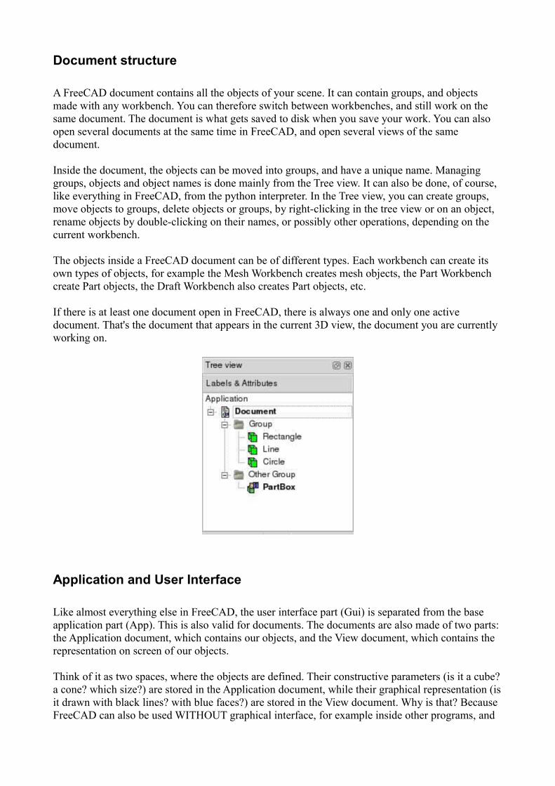
Inside the document, the objects can be moved into groups, and have a unique name. Managing groups, objects and object names is done mainly from the Tree view. It can also be done, of course, like everything in FreeCAD, from the python interpreter. In the Tree view, you can create groups, move objects to groups, delete objects or groups, by right-clicking in the tree view or on an object, rename objects by double-clicking on their names, or possibly other operations, depending on the current workbench.
The objects inside a FreeCAD document can be of different types. Each workbench can create its own types of objects, for example the Mesh Workbench creates mesh objects, the Part Workbench create Part objects, the Draft Workbench also creates Part objects, etc.
If there is at least one document open in FreeCAD, there is always one and only one active document. That's the document that appears in the current 3D view, the document you are currently working on.
Application and User Interface
Like almost everything else in FreeCAD, the user interface part (Gui) is separated from the base application part (App). This is also valid for documents. The documents are also made of two parts: the Application document, which contains our objects, and the View document, which contains the representation on screen of our objects.
Think of it as two spaces, where the objects are defined. Their constructive parameters (is it a cube?a cone? which size?) are stored in the Application document, while their graphical representation (isit drawn with black lines? with blue faces?) are stored in the View document. Why is that? Because FreeCAD can also be used WITHOUT graphical interface, for example inside other programs, and

we must still be able to manipulate our objects, even if nothing is drawn on the screen.
Another thing that is contained inside the View document are 3D views. One document can have several views opened, so you can inspect your document from several points of view at the same time. Maybe you would want to see a top view and a front view of your work at the same time? Then, you will have two views of the same document, both stored in the View document. Creating new views or closing views can be done from the View menu or by right-clicking on a view tab.
Scripting
Documents can be easily created, accessed and modified from the python interpreter. For example:
FreeCAD.ActiveDocument
Will return the current (active) document
FreeCAD.ActiveDocument.Blob
Would access an object called "Blob" inside your document
FreeCADGui.ActiveDocument
Will return the view document associated to the current document
FreeCADGui.ActiveDocument.Blob
Would access the graphical representation (view) part of our Blob object
FreeCADGui.ActiveDocument.ActiveView
Will return the current view
Part Module
The CAD capabilities of FreeCAD are based on the OpenCasCade kernel. The Part module allows FreeCAD to access and use the OpenCasCade objects and functions. OpenCascade is a professional-level CAD kernel, that features advanced 3D geometry manipulation and objects. The Part objects, unlike Mesh Module objects, are much more complex, and therefore permit much more advanced operations, like coherent boolean operations, modifications history and parametric behaviour.
Explaining the concepts
In OpenCasCade terminology, we distinguish between geometric primitives and (topological) shapes. A geometric primitive can be a point, a line, a circle, a plane, etc. or even some more complex types like a B-Spline curve or surface. A shape can be a vertex, an edge, a wire, a face, a solid or a compound of other shapes. The geometric primitives are not made to be directly displayed
on the 3D scene, but rather to be used as building geometry for shapes. For example, an edge can beconstructed from a line or from a portion of a circle.
We could say, to resume, that geometry primitive are "shapeless" building blocks, and shapes are the real spatial geometry built on it.
To get a complete list of all of them refer to the OCC documentation (Alternative: sourcearchive.com) and search for Geom_* (for geometry) and TopoDS_* (for shapes). There you can also read more about the differences between geometric objects and shapes. Please note that unfortunately the official OCC documentation is not available online (you must download an archive) and is mostly aimed at programmers, not at end-users. But hopefully you'll find enough information to get started here.
The geometric types actually can be divided into two major groups: curves and surfaces. Out of the curves (line, circle, ...) you can directly build an edge, out of the surfaces (plane, cylinder, ...) a face can be built. For example, the geometric primitive line is unlimited, i.e. it is defined by a base vector and a direction vector while its shape representation must be something limited by a start andend point. And a box -- a solid -- can be created by six limited planes.
From an edge or face you can also go back to its geometric primitive counter part.
Thus, out of shapes you can build very complex parts or, the other way round, extract all sub-shapesa more complex shape is made of.
Scripting
The main data structure used in the Part module is the BRep data type from OpenCascade. Almost all contents and object types of the Part module are now available to python scripting. This includesgeometric primitives, such as Line and Circle (or Arc), and the whole range of TopoShapes, like Vertexes, Edges, Wires, Faces, Solids and Compounds. For each of those objects, several creation methods exist, and for some of them, especially the TopoShapes, advanced operations like boolean union/difference/intersection are also available. Explore the contents of the Part module, as described in the FreeCAD Scripting Basics page, to know more.
Examples
To create a line element switch to the Python console and type in:
import Part,PartGui doc=App.newDocument() l=Part.Line() l.StartPoint=(0.0,0.0,0.0) l.EndPoint=(1.0,1.0,1.0) doc.addObject("Part::Feature","Line").Shape=l.toShape()
doc.recompute()
Let's go through the above python example step by step:
import Part,PartGui doc=App.newDocument()
loads the Part module and creates a new document
l=Part.Line() l.StartPoint=(0.0,0.0,0.0) l.EndPoint=(1.0,1.0,1.0)
Line is actually a line segment, hence the start and endpoint.
doc.addObject("Part::Feature","Line").Shape=l.toShape()
This adds a Part object type to the document and assigns the shape representation of the line segment to the 'Shape' property of the added object. It is important to understand here that we used ageometric primitive (the Part.Line) to create a TopoShape out of it (the toShape() method). Only Shapes can be added to the document. In FreeCAD, geometry primitives are used as "building structures" for Shapes.
doc.recompute()
Updates the document. This also prepares the visual representation of the new part object.
Note that a Line can be created by specifying its start and endpoint directly in the constructor, for example Part.Line(point1,point2), or we can create a default line and set its properties afterwards, aswe did here.
A circle can be created in a similar way:
import Part doc = App.activeDocument() c = Part.Circle() c.Radius=10.0 f = doc.addObject("Part::Feature", "Circle") f.Shape = c.toShape() doc.recompute()
Note again, we used the circle (geometry primitive) to construct a shape out of it. We can of course still access our construction geometry afterwards, by doing:
s = f.Shape e = s.Edges[0] c = e.Curve
Here we take the shape of our object f, then we take its list of edges. In this case there will be only one because we made the whole shape out of a single circle, so we take only the first item of the Edges list, and we takes its curve. Every Edge has a Curve, which is the geometry primitive it is based on.
Head to the Topological data scripting page if you would like to know more.
FreeCAD Scripting Basics
Python scripting in FreeCAD
FreeCAD is built from scratch to be totally controlled by Python scripts. Almost all parts of FreeCAD, such as the interface, the scene contents, and even the representation of this content in the 3D views, are accessible from the built-in Python interpreter or from your own scripts. As a result, FreeCAD is probably one of the most deeply customizable engineering applications availabletoday.
In its current state however, FreeCAD has very few 'native' commands to interact with your 3D objects, mainly because it is still in the early stages of development, but also because the philosophybehind it is more to provide a platform for CAD development than a specific use application. But the ease of Python scripting inside FreeCAD is a quick way to see new functionality being developed by 'power users', typically users who know a bit of Python programming. Python is one of the most popular interpreted languages, and because it is generally regarded as easy to learn, you too can soon be making your own FreeCAD 'power user' scripts.
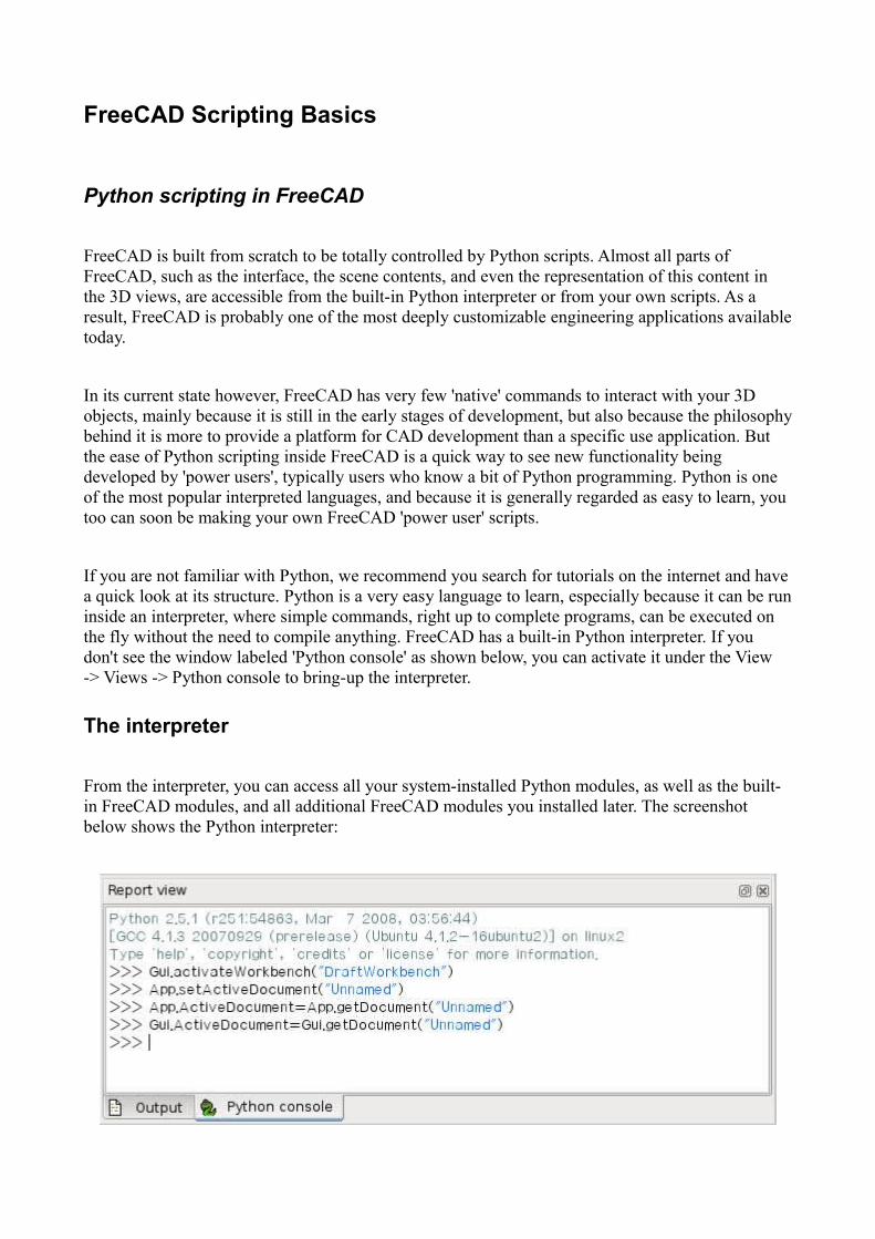
If you are not familiar with Python, we recommend you search for tutorials on the internet and havea quick look at its structure. Python is a very easy language to learn, especially because it can be runinside an interpreter, where simple commands, right up to complete programs, can be executed on the fly without the need to compile anything. FreeCAD has a built-in Python interpreter. If you don't see the window labeled 'Python console' as shown below, you can activate it under the View -> Views -> Python console to bring-up the interpreter.
The interpreter
From the interpreter, you can access all your system-installed Python modules, as well as the built-in FreeCAD modules, and all additional FreeCAD modules you installed later. The screenshot below shows the Python interpreter:
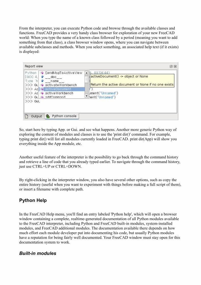
From the interpreter, you can execute Python code and browse through the available classes and functions. FreeCAD provides a very handy class browser for exploration of your new FreeCAD world: When you type the name of a known class followed by a period (meaning you want to add something from that class), a class browser window opens, where you can navigate between available subclasses and methods. When you select something, an associated help text (if it exists) is displayed:
So, start here by typing App. or Gui. and see what happens. Another more generic Python way of exploring the content of modules and classes is to use the 'print dir()' command. For example, typing print dir() will list all modules currently loaded in FreeCAD. print dir(App) will show you everything inside the App module, etc.
Another useful feature of the interpreter is the possibility to go back through the command history and retrieve a line of code that you already typed earlier. To navigate through the command history, just use CTRL+UP or CTRL+DOWN.
By right-clicking in the interpreter window, you also have several other options, such as copy the entire history (useful when you want to experiment with things before making a full script of them),or insert a filename with complete path.
Python Help
In the FreeCAD Help menu, you'll find an entry labeled 'Python help', which will open a browser window containing a complete, realtime-generated documentation of all Python modules available to the FreeCAD interpreter, including Python and FreeCAD built-in modules, system-installed modules, and FreeCAD additional modules. The documentation available there depends on how much effort each module developer put into documenting his code, but usually Python modules have a reputation for being fairly well documented. Your FreeCAD window must stay open for this documentation system to work.
Built-in modules

Since FreeCAD is designed to be run without a Graphical User Interface (GUI), almost all its functionality is separated into two groups: Core functionality, named 'App', and GUI functionality, named 'Gui'. So, our two main FreeCAD built-in modules are called App and Gui. These two modules can also be accessed from scripts outside of the interpreter, by the names 'FreeCAD' and 'FreeCADGui' respectively.
In the App module, you'll find everything related to the application itself, like methods for opening or closing files, and to the documents, like setting the active document or listing their contents.
In the Gui module, you'll find tools for accessing and managing Gui elements, like the workbenches and their toolbars, and, more interestingly, the graphical representation of all FreeCAD content.
Listing all the content of those modules is a bit counter-productive task, since they grow quite fast with FreeCAD development. But the two browsing tools provided (the class browser and the Python help) should give you, at any moment, complete and up-to-date documentation of these modules.
The App and Gui objects
As we said, in FreeCAD, everything is separated between core and representation. This includes the3D objects too. You can access defining properties of objects (called features in FreeCAD) via the App module, and change the way they are represented on screen via the Gui module. For example, acube has properties that define it, (like width, length, height) that are stored in an App object, and representation properties, (like faces color, drawing mode) that are stored in a corresponding Gui object.
This way of doing things allows a very wide range of uses, like having algorithms work only on the definition part of features, without the need to care about any visual part, or even redirect the content of the document to non-graphical application, such as lists, spreadsheets, or element analysis.
For every App object in your document, there exists a corresponding Gui object. Infact the document itself has both App and a Gui objects. This, of course, is only valid when you run FreeCAD with its full interface. In the command-line version no GUI exists, so only App objects are availible. Note that the Gui part of objects is re-generated every time an App object is marked as'to be recomputed' (for example when one of its parameters changes), so changes you might have made directly to the Gui object may be lost.
To access the App part of something, you type:
myObject = App.ActiveDocument.getObject("ObjectName")
where "ObjectName" is the name of your object. You can also type:
myObject = App.ActiveDocument.ObjectName
To access the Gui part of the same object, you type:
myViewObject = Gui.ActiveDocument.getObject("ObjectName")
where "ObjectName" is the name of your object. You can also type:
myViewObject = App.ActiveDocument.ObjectName.ViewObject
If we have no GUI (for example we are in command-line mode), the last line will return 'None'.
The Document objects
In FreeCAD all your work resides inside Documents. A document contains your geometry and can be saved to a file. Several documents can be opened at the same time. The document, like the geometry contained inside, has App and Gui objects. App object contains your actual geometry definitions, while the Gui object contains the different views of your document. You can open several windows, each one viewing your work with a different zoom factor or point of view. These views are all part of your document's Gui object.
To access the App part the currently open (active) document, you type:
myDocument = App.ActiveDocument
To create a new document, type:
myDocument = App.newDocument("Document Name")
To access the Gui part the currently open (active) document, you type:
myGuiDocument = Gui.ActiveDocument
To access the current view, you type:
myView = Gui.ActiveDocument.ActiveView
Using additional modules

The FreeCAD and FreeCADGui modules are solely responsibles for creating and managing objects in the FreeCAD document. They don't actually do anything such as creating or modifying geometry.That is because that geometry can be of several types, and so it is managed by additional modules, each responsible for managing a certain geometry type. For example, the Part Module uses the OpenCascade kernel, and therefore is able to create and manipulate B-rep type geometry, which is what OpenCascade is built for. The Mesh Module is able to build and modify mesh objects. That way, FreeCAD is able to handle a wide variety of object types, that can all coexist in the same document, and new types could be added easily in the future.
Creating objects
Each module has its own way to treat its geometry, but one thing they usually all can do is create objects in the document. But the FreeCAD document is also aware of the available object types provided by the modules:
FreeCAD.ActiveDocument.supportedTypes()
will list you all the possible objects you can create. For example, let's create a mesh (treated by the mesh module) and a part (treated by the part module):
myMesh = FreeCAD.ActiveDocument.addObject("Mesh::Feature","myMeshName")myPart = FreeCAD.ActiveDocument.addObject("Part::Feature","myPartName")
The first argument is the object type, the second the name of the object. Our two objects look almost the same: They don't contain any geometry yet, and most of their properties are the same when you inspect them with dir(myMesh) and dir(myPart). Except for one, myMesh has a "Mesh" property and "Part" has a "Shape" property. That is where the Mesh and Part data are stored. For example, let's create a Part cube and store it in our myPart object:
import Partcube = Part.makeBox(2,2,2)myPart.Shape = cube
You could try storing the cube inside the Mesh property of the myMesh object, it will return an error complaining of the wrong type. That is because those properties are made to store only a certain type. In the myMesh's Mesh property, you can only save stuff created with the Mesh module. Note that most modules also have a shortcut to add their geometry to the document:
import Partcube = Part.makeBox(2,2,2)Part.show(cube)
Modifying objects
Modifying an object is done the same way:

import Partcube = Part.makeBox(2,2,2)myPart.Shape = cube
Now let's change the shape by a bigger one:
biggercube = Part.makeBox(5,5,5)myPart.Shape = biggercube
Querying objects
You can always look at the type of an object like this:
myObj = FreeCAD.ActiveDocument.getObject("myObjectName")print myObj.Type
or know if an object is derived from one of the basic ones (Part Feature, Mesh Feature, etc):
print myObj.isDerivedFrom("Part::Feature")
Now you can really start playing with FreeCAD! To look at what you can do with the Part Module, read the Part scripting page, or the Mesh Scripting page for working with the Mesh Module. Note that, although the Part and Mesh modules are the most complete and widely used, other modules such as the Draft Module also have scripting APIs that can be useful to you. For a complete list of each modules and their available tools, visit the Category:API section.
Mesh Scripting
Introduction
First of all you have to import the Mesh module:
import Mesh
After that you have access to the Mesh module and the Mesh class which facilitate the functions of the FreeCAD C++ Mesh-Kernel.
Creation and Loading
To create an empty mesh object just use the standard constructor:
mesh = Mesh.Mesh()
You can also create an object from a file
mesh = Mesh.Mesh('D:/temp/Something.stl')
(A list of compatible filetypes can be found under 'Meshes' here.)
Or create it out of a set of triangles described by their corner points:
planarMesh = [
# triangle 1
[-0.5000,-0.5000,0.0000],[0.5000,0.5000,0.0000],[-0.5000,0.5000,0.0000],
#triangle 2
[-0.5000,-0.5000,0.0000],[0.5000,-0.5000,0.0000],[0.5000,0.5000,0.0000],
]
planarMeshObject = Mesh.Mesh(planarMesh)
The Mesh-Kernel takes care about creating a topological correct data structure by sorting coincidentpoints and edges together.
Later on you will see how you can test and examine mesh data.

Modeling
To create regular geometries you can use the Python script BuildRegularGeoms.py.
import BuildRegularGeoms
This script provides methods to define simple rotation bodies like spheres, ellipsoids, cylinders, toroids and cones. And it also has a method to create a simple cube. To create a toroid, for instance, can be done as follows:
t = BuildRegularGeoms.Toroid(8.0, 2.0, 50) # list with several thousands triangles
m = Mesh.Mesh(t)
The first two parameters define the radiuses of the toroid and the third parameter is a sub-sampling factor for how many triangles are created. The higher this value the smoother and the lower the coarser the body is. The Mesh class provides a set of boolean functions that can be used for modeling purposes. It provides union, intersection and difference of two mesh objects.
m1, m2 # are the input mesh objects
m3 = Mesh.Mesh(m1) # create a copy of m1
m3.unite(m2) # union of m1 and m2, the result is stored in m3
m4 = Mesh.Mesh(m1)
m4.intersect(m2) # intersection of m1 and m2
m5 = Mesh.Mesh(m1)
m5.difference(m2) # the difference of m1 and m2
m6 = Mesh.Mesh(m2)
m6.difference(m1) # the difference of m2 and m1, usually the result is different to m5
Finally, a full example that computes the intersection between a sphere and a cylinder that intersectsthe sphere.
import Mesh, BuildRegularGeoms
sphere = Mesh.Mesh( BuildRegularGeoms.Sphere(5.0, 50) )
cylinder = Mesh.Mesh( BuildRegularGeoms.Cylinder(2.0, 10.0, True, 1.0, 50) )
diff = sphere
diff.difference(cylinder)
d = FreeCAD.newDocument()
d.addObject("Mesh::Feature","Diff_Sphere_Cylinder").Mesh=diff
d.recompute()

Examining and Testing
Write your own Algorithms
Exporting
You can even write the mesh to a python module:
m.write("D:/Develop/Projekte/FreeCAD/FreeCAD_0.7/Mod/Mesh/SavedMesh.py")
import SavedMesh
m2 = Mesh.Mesh(SavedMesh.faces)
Gui related stuff
Odds and Ends
An extensive (though hard to use) source of Mesh related scripting are the unit test scripts of the Mesh-Module. In this unit tests literally all methods are called and all properties/attributes are tweaked. So if you are bold enough, take a look at the Unit Test module.

Topological data scripting
Introduction
We will here explain you how to control the Part Module directly from the FreeCAD python interpreter, or from any external script. Be sure to browse the Scripting section and the FreeCAD Scripting Basics pages if you need more information about how python scripting works in FreeCAD.
Class Diagram
This is a Unified Modeling Language (UML) overview of the most important classes of the Part module:
Python classes of the Part module
Geometry
The geometric objects are the building block of all topological objects:

Geom Base class of the geometric objects
Line A straight line in 3D, defined by starting point and and point
Circle Circle or circle segment defined by a center point and start and end point
...... And soon some more ;-)
Topology
The following topological data types are available:
Compound A group of any type of topological object.
Compsolid A composite solid is a set of solids connected by their faces. It expands the notions of WIRE and SHELL to solids.
Solid A part of space limited by shells. It is three dimensional.
Shell A set of faces connected by their edges. A shell can be open or closed.
Face In 2D it is part of a plane; in 3D it is part of a surface. Its geometry is constrained (trimmed)by contours. It is two dimensional.
Wire A set of edges connected by their vertices. It can be an open or closed contour depending onwhether the edges are linked or not.
Edge A topological element corresponding to a restrained curve. An edge is generally limited by vertices. It has one dimension.
Vertex A topological element corresponding to a point. It has zero dimension.
Shape A generic term covering all of the above.
Quick example : Creating simple topology
We will now create a topology by constructing it out of simpler geometry. As a case study we use a part as seen in the picture which consists of four vertexes, two circles and two lines.
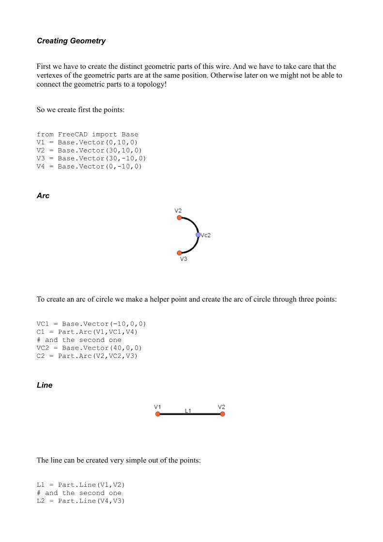
Creating Geometry
First we have to create the distinct geometric parts of this wire. And we have to take care that the vertexes of the geometric parts are at the same position. Otherwise later on we might not be able to connect the geometric parts to a topology!
So we create first the points:
from FreeCAD import BaseV1 = Base.Vector(0,10,0)V2 = Base.Vector(30,10,0)V3 = Base.Vector(30,-10,0)V4 = Base.Vector(0,-10,0)
Arc
To create an arc of circle we make a helper point and create the arc of circle through three points:
VC1 = Base.Vector(-10,0,0)C1 = Part.Arc(V1,VC1,V4)# and the second oneVC2 = Base.Vector(40,0,0)C2 = Part.Arc(V2,VC2,V3)
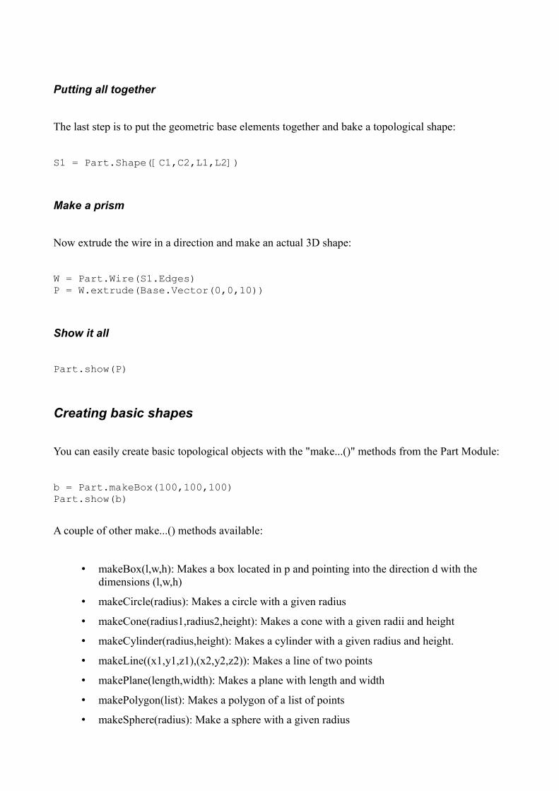
Line
The line can be created very simple out of the points:
L1 = Part.Line(V1,V2)# and the second oneL2 = Part.Line(V4,V3)
Putting all together
The last step is to put the geometric base elements together and bake a topological shape:
S1 = Part.Shape([C1,C2,L1,L2])
Make a prism
Now extrude the wire in a direction and make an actual 3D shape:
W = Part.Wire(S1.Edges)P = W.extrude(Base.Vector(0,0,10))
Show it all
Part.show(P)
Creating basic shapes
You can easily create basic topological objects with the "make...()" methods from the Part Module:
b = Part.makeBox(100,100,100)Part.show(b)
A couple of other make...() methods available:
• makeBox(l,w,h): Makes a box located in p and pointing into the direction d with the dimensions (l,w,h)
• makeCircle(radius): Makes a circle with a given radius
• makeCone(radius1,radius2,height): Makes a cone with a given radii and height
• makeCylinder(radius,height): Makes a cylinder with a given radius and height.
• makeLine((x1,y1,z1),(x2,y2,z2)): Makes a line of two points
• makePlane(length,width): Makes a plane with length and width
• makePolygon(list): Makes a polygon of a list of points
• makeSphere(radius): Make a sphere with a given radius

• makeTorus(radius1,radius2): Makes a torus with a given radii
See the Part API page for a complete list of available methods of the Part module.
Importing the needed modules
First we need to import the Part module so we can use its contents in python. We'll also import the Base module from inside the FreeCAD module:
import Partfrom FreeCAD import Base
Creating a Vector
Vectors are one of the most important pieces of information when building shapes. They contain a 3numbers usually (but not necessarily always) the x, y and z cartesian coordinates. You create a vector like this:
myVector = Base.Vector(3,2,0)
We just created a vector at coordinates x=3, y=2, z=0. In the Part module, vectors are used everywhere. Part shapes also use another kind of point representation, called Vertex, which is acually nothing else than a container for a vector. You access the vector of a vertex like this:
myVertex = myShape.Vertexes[0]print myVertex.Point> Vector (3, 2, 0)
Creating an Edge
An edge is nothing but a line with two vertexes:
edge = Part.makeLine((0,0,0), (10,0,0))edge.Vertexes> [<Vertex object at 01877430>, <Vertex object at 014888E0>]
Note: You can also create an edge by passing two vectors:
vec1 = Base.Vector(0,0,0)vec2 = Base.Vector(10,0,0)line = Part.Line(vec1,vec2)edge = line.toShape()
You can find the length and center of an edge like this:

edge.Length> 10.0edge.CenterOfMass> Vector (5, 0, 0)
Putting the shape on screen
So far we created an edge object, but it doesn't appear anywhere on screen. This is because we just manipulated python objects here. The FreeCAD 3D scene only displays what you tell it to display. To do that, we use this simple method:
Part.show(edge)
An object will be created in our FreeCAD document, and our "edge" shape will be attributed to it. Use this whenever it's time to display your creation on screen.
Creating a Wire
A wire is a multi-edge line and can be created from a list of edges or even a list of wires:
edge1 = Part.makeLine((0,0,0), (10,0,0))edge2 = Part.makeLine((10,0,0), (10,10,0))wire1 = Part.Wire([edge1,edge2]) edge3 = Part.makeLine((10,10,0), (0,10,0))edge4 = Part.makeLine((0,10,0), (0,0,0))wire2 = Part.Wire([edge3,edge4])wire3 = Part.Wire([wire1,wire2])wire3.Edges> [<Edge object at 016695F8>, <Edge object at 0197AED8>, <Edge object at 01828B20>, <Edge object at 0190A788>]Part.show(wire3)
Part.show(wire3) will display the 4 edges that compose our wire. Other useful information can be easily retrieved:
wire3.Length> 40.0wire3.CenterOfMass> Vector (5, 5, 0)wire3.isClosed()> Truewire2.isClosed()> False
Creating a Face
Only faces created from closed wires will be valid. In this example, wire3 is a closed wire but wire2
is not a closed wire (see above)
face = Part.Face(wire3)face.Area> 99.999999999999972face.CenterOfMass> Vector (5, 5, 0)face.Length> 40.0face.isValid()> Truesface = Part.Face(wire2)face.isValid()> False
Only faces will have an area, not wires nor edges.
Creating a Circle
A circle can be created as simply as this:
circle = Part.makeCircle(10)circle.Curve> Circle (Radius : 10, Position : (0, 0, 0), Direction : (0, 0, 1))
If you want to create it at certain position and with certain direction:
ccircle = Part.makeCircle(10, Base.Vector(10,0,0), Base.Vector(1,0,0))ccircle.Curve> Circle (Radius : 10, Position : (10, 0, 0), Direction : (1, 0, 0))
ccircle will be created at distance 10 from origin on x and will be facing towards x axis. Note: makeCircle only accepts Base.Vector() for position and normal but not tuples. You can also create part of the circle by giving start angle and end angle as:
from math import piarc1 = Part.makeCircle(10, Base.Vector(0,0,0), Base.Vector(0,0,1), 0, 180)arc2 = Part.makeCircle(10, Base.Vector(0,0,0), Base.Vector(0,0,1), 180, 360)
Both arc1 and arc2 jointly will make a circle. Angles should be provided in degrees, if you have radians simply convert them using formula: degrees = radians * 180/PI or using python's math module (after doing import math, of course):
degrees = math.degrees(radians)
Creating an Arc along points

Unfortunately there is no makeArc function but we have Part.Arc function to create an arc along three points. Basically it can be supposed as an arc joining start point and end point along the middle point. Part.Arc creates an arc object on which .toShape() has to be called to get the edge object, the same way as when using Part.Line instead of Part.makeLine.
arc = Part.Arc(Base.Vector(0,0,0),Base.Vector(0,5,0),Base.Vector(5,5,0))arc> <Arc object>arc_edge = arc.toShape()
Arc only accepts Base.Vector() for points but not tuples. arc_edge is what we want which we can display using Part.show(arc_edge). You can also obtain an arc by using a portion of a circle:
from math import picircle = Part.Circle(Base.Vector(0,0,0),Base.Vector(0,0,1),10)arc = Part.Arc(c,0,pi)
Arcs are valid edges, like lines. So they can be used in wires too.
Creating a polygon
A polygon is simply a wire with multiple straight edges. The makePolygon function takes a list of points and creates a wire along those points:
lshape_wire = Part.makePolygon([Base.Vector(0,5,0),Base.Vector(0,0,0),Base.Vector(5,0,0)])
Creating a Bezier curve
Bézier curves are used to model smooth curves using a series of poles (points) and optional weights.The function below makes a Part.BezierCurve from a series of FreeCAD.Vector points. (Note: pole and weight indices start at 1, not 0.)
def makeBCurve(Points): c = Part.BezierCurve() c.setPoles(Points) return(c)
Creating a Plane
A Plane is simply a flat rectangular surface. The method used to create one is this: makePlane(length,width,[start_pnt,dir_normal]). By default start_pnt = Vector(0,0,0) and dir_normal = Vector(0,0,1). Using dir_normal = Vector(0,0,1) will create the plane facing z axis, while dir_normal = Vector(1,0,0) will create the plane facing x axis:

plane = Part.makePlane(2,2)plane><Face object at 028AF990>plane = Part.makePlane(2,2, Base.Vector(3,0,0), Base.Vector(0,1,0))plane.BoundBox> BoundBox (3, 0, 0, 5, 0, 2)
BoundBox is a cuboid enclosing the plane with a diagonal starting at (3,0,0) and ending at (5,0,2). Here the BoundBox thickness in y axis is zero, since our shape is totally flat.
Note: makePlane only accepts Base.Vector() for start_pnt and dir_normal but not tuples
Creating an ellipse
To create an ellipse there are several ways:
Part.Ellipse()
Creates an ellipse with major radius 2 and minor radius 1 with the center in (0,0,0)
Part.Ellipse(Ellipse)
Create a copy of the given ellipse
Part.Ellipse(S1,S2,Center)
Creates an ellipse centered on the point Center, where the plane of the ellipse is defined by Center, S1 and S2, its major axis is defined by Center and S1, its major radius is the distance between Center and S1, and its minor radius is the distance between S2 and the major axis.
Part.Ellipse(Center,MajorRadius,MinorRadius)
Creates an ellipse with major and minor radii MajorRadius and MinorRadius, and located in the plane defined by Center and the normal (0,0,1)
eli = Part.Ellipse(Base.Vector(10,0,0),Base.Vector(0,5,0),Base.Vector(0,0,0))Part.show(eli.toShape())
In the above code we have passed S1, S2 and center. Similarly to Arc, Ellipse also creates an ellipse object but not edge, so we need to convert it into edge using toShape() to display.
Note: Arc only accepts Base.Vector() for points but not tuples
eli = Part.Ellipse(Base.Vector(0,0,0),10,5)Part.show(eli.toShape())
for the above Ellipse constructor we have passed center, MajorRadius and MinorRadius
Creating a Torus
Using the method makeTorus(radius1,radius2,[pnt,dir,angle1,angle2,angle]). By default pnt=Vector(0,0,0),dir=Vector(0,0,1),angle1=0,angle2=360 and angle=360. Consider a torus as smallcircle sweeping along a big circle. Radius1 is the radius of big cirlce, radius2 is the radius of small circle, pnt is the center of torus and dir is the normal direction. angle1 and angle2 are angles in radians for the small circle, the last parameter angle is to make a section of the torus:
torus = Part.makeTorus(10, 2)
The above code will create a torus with diameter 20(radius 10) and thickness 4 (small cirlce radius 2)
tor=Part.makeTorus(10,5,Base.Vector(0,0,0),Base.Vector(0,0,1),0,180)
The above code will create a slice of the torus
tor=Part.makeTorus(10,5,Base.Vector(0,0,0),Base.Vector(0,0,1),0,360,180)
The above code will create a semi torus, only the last parameter is changed i.e the angle and remaining angles are defaults. Giving the angle 180 will create the torus from 0 to 180, that is, a half torus.
Creating a box or cuboid
Using makeBox(length,width,height,[pnt,dir]). By default pnt=Vector(0,0,0) and dir=Vector(0,0,1)
box = Part.makeBox(10,10,10)len(box.Vertexes)> 8
Creating a Sphere
Using makeSphere(radius,[pnt, dir, angle1,angle2,angle3]). By default pnt=Vector(0,0,0), dir=Vector(0,0,1), angle1=-90, angle2=90 and angle3=360. angle1 and angle2 are the vertical minimum and maximum of the sphere, angle3 is the sphere diameter itself.
sphere = Part.makeSphere(10)hemisphere = Part.makeSphere(10,Base.Vector(0,0,0),Base.Vector(0,0,1),-

90,90,180)
Creating a Cylinder
Using makeCylinder(radius,height,[pnt,dir,angle]). By default pnt=Vector(0,0,0),dir=Vector(0,0,1) and angle=360
cylinder = Part.makeCylinder(5,20)partCylinder = Part.makeCylinder(5,20,Base.Vector(20,0,0),Base.Vector(0,0,1),180)
Creating a Cone
Using makeCone(radius1,radius2,height,[pnt,dir,angle]). By default pnt=Vector(0,0,0), dir=Vector(0,0,1) and angle=360
cone = Part.makeCone(10,0,20)semicone = Part.makeCone(10,0,20,Base.Vector(20,0,0),Base.Vector(0,0,1),180)
Modifying shapes
There are several ways to modify shapes. Some are simple transformation operations such as moving or rotating shapes, other are more complex, such as unioning and subtracting one shape from another. Be aware that
Transform operations
Translating a shape
Translating is the act of moving a shape from one place to another. Any shape (edge, face, cube, etc...) can be translated the same way:
myShape = Part.makeBox(2,2,2)myShape.translate(Base.Vector(2,0,0))
This will move our shape "myShape" 2 units in the x direction.
Rotating a shape
To rotate a shape, you need to specify the rotation center, the axis, and the rotation angle:
myShape.rotate(Vector(0,0,0),Vector(0,0,1),180)
The above code will rotate the shape 180 degrees around the Z Axis.

Generic transformations with matrixes
A matrix is a very convenient way to store transformations in the 3D world. In a single matrix, you can set translation, rotation and scaling values to be applied to an object. For example:
myMat = Base.Matrix()myMat.move(Base.Vector(2,0,0))myMat.rotateZ(math.pi/2)
Note: FreeCAD matrixes work in radians. Also, almost all matrix operations that take a vector can also take 3 numbers, so those 2 lines do the same thing:
myMat.move(2,0,0)myMat.move(Base.Vector(2,0,0))
When our matrix is set, we can apply it to our shape. FreeCAD provides 2 methods to do that: transformShape() and transformGeometry(). The difference is that with the first one, you are sure that no deformations will occur (see "scaling a shape" below). So we can apply our transformation like this:
myShape.trasformShape(myMat)
or
myShape.transformGeometry(myMat)
Scaling a shape
Scaling a shape is a more dangerous operation because, unlike translation or rotation, scaling non-uniformly (with different values for x, y and z) can modify the structure of the shape. For example, scaling a circle with a higher value horizontally than vertically will transform it into an ellipse, which behaves mathematically very differenty. For scaling, we can't use the transformShape, we must use transformGeometry():
myMat = Base.Matrix()myMat.scale(2,1,1)myShape=myShape.transformGeometry(myMat)
Boolean Operations
Subtraction
Subtracting a shape from another one is called "cut" in OCC/FreeCAD jargon and is done like this:

cylinder = Part.makeCylinder(3,10,Base.Vector(0,0,0),Base.Vector(1,0,0))sphere = Part.makeSphere(5,Base.Vector(5,0,0))diff = cylinder.cut(sphere)
Intersection
The same way, the intersection between 2 shapes is called "common" and is done this way:
cylinder1 = Part.makeCylinder(3,10,Base.Vector(0,0,0),Base.Vector(1,0,0))cylinder2 = Part.makeCylinder(3,10,Base.Vector(5,0,-5),Base.Vector(0,0,1))common = cylinder1.common(cylinder2)
Union
Union is called "fuse" and works the same way:
cylinder1 = Part.makeCylinder(3,10,Base.Vector(0,0,0),Base.Vector(1,0,0))cylinder2 = Part.makeCylinder(3,10,Base.Vector(5,0,-5),Base.Vector(0,0,1))fuse = cylinder1.fuse(cylinder2)
Section
A Section is the intersection between a solid shape and a plane shape. It will return an intersection curve, a compound with edges
cylinder1 = Part.makeCylinder(3,10,Base.Vector(0,0,0),Base.Vector(1,0,0))cylinder2 = Part.makeCylinder(3,10,Base.Vector(5,0,-5),Base.Vector(0,0,1))section = cylinder1.section(cylinder2)section.Wires> []section.Edges> [<Edge object at 0D87CFE8>, <Edge object at 019564F8>, <Edge object at 0D998458>, <Edge object at 0D86DE18>, <Edge object at 0D9B8E80>, <Edge object at 012A3640>, <Edge object at 0D8F4BB0>]
Extrusion
Extrusion is the act of "pushing" a flat shape in a certain direction resulting in a solid body. Think ofa circle becoming a tube by "pushing it out":
circle = Part.makeCircle(10)

tube = circle.extrude(Base.Vector(0,0,2))
If your circle is hollow, you will obtain a hollow tube. If your circle is actually a disc, with a filled face, you will obtain a solid cylinder:
wire = Part.Wire(circle)disc = Part.makeFace(wire)cylinder = disc.extrude(Base.Vector(0,0,2))
Exploring shapes
You can easily explore the topological data structure:
import Partb = Part.makeBox(100,100,100)b.Wiresw = b.Wires[0]ww.Wiresw.VertexesPart.show(w)w.Edgese = w.Edges[0]e.Vertexesv = e.Vertexes[0]v.Point
By typing the lines above in the python interpreter, you will gain a good understanding of the structure of Part objects. Here, our makeBox() command created a solid shape. This solid, like all Part solids, contains faces. Faces always contain wires, which are lists of edges that border the face. Each face has at least one closed wire (it can have more if the face has a hole). In the wire, we can look at each edge separately, and inside each edge, we can see the vertexes. Straight edges have only two vertexes, obviously.
Edge analysis
In case of an edge, which is an arbitrary curve, it's most likely you want to do a discretization. In FreeCAD the edges are parametrized by their lengths. That means you can walk an edge/curve by its length:
import Partbox = Part.makeBox(100,100,100)anEdge = box.Edges[0]print anEdge.Length
Now you can access a lot of properties of the edge by using the length as a position. That means if the edge is 100mm long the start position is 0 and the end position 100.
anEdge.tangentAt(0.0) # tangent direction at the beginninganEdge.valueAt(0.0) # Point at the beginninganEdge.valueAt(100.0) # Point at the end of the edgeanEdge.derivative1At(50.0) # first derivative of the curve in the middleanEdge.derivative2At(50.0) # second derivative of the curve in the middleanEdge.derivative3At(50.0) # third derivative of the curve in the middleanEdge.centerOfCurvatureAt(50) # center of the curvature for that positionanEdge.curvatureAt(50.0) # the curvatureanEdge.normalAt(50) # normal vector at that position (if defined)
Using the selection
Here we see now how we can use the selection the user did in the viewer. First of all we create a box and shows it in the viewer
import PartPart.show(Part.makeBox(100,100,100))Gui.SendMsgToActiveView("ViewFit")
Select now some faces or edges. With this script you can iterate all selected objects and their sub elements:
for o in Gui.Selection.getSelectionEx():print o.ObjectNamefor s in o.SubElementNames:
print "name: ",sfor s in o.SubObjects:
print "object: ",s
Select some edges and this script will calculate the length:
length = 0.0for o in Gui.Selection.getSelectionEx():
for s in o.SubObjects:length += s.Length
print "Length of the selected edges:" ,length
Complete example: The OCC bottle
A typical example found on the OpenCasCade Getting Started Page is how to build a bottle. This is a good exercise for FreeCAD too. In fact, you can follow our example below and the OCC page simultaneously, you will understand well how OCC structures are implemented in FreeCAD. The complete script below is also included in FreeCAD installation (inside the Mod/Part folder) and canbe called from the python interpreter by typing:
import Partimport MakeBottle
bottle = MakeBottle.makeBottle()Part.show(bottle)
The complete script
Here is the complete MakeBottle script:
import Part, FreeCAD, mathfrom FreeCAD import Base
def makeBottle(myWidth=50.0, myHeight=70.0, myThickness=30.0): aPnt1=Base.Vector(-myWidth/2.,0,0) aPnt2=Base.Vector(-myWidth/2.,-myThickness/4.,0) aPnt3=Base.Vector(0,-myThickness/2.,0) aPnt4=Base.Vector(myWidth/2.,-myThickness/4.,0) aPnt5=Base.Vector(myWidth/2.,0,0) aArcOfCircle = Part.Arc(aPnt2,aPnt3,aPnt4) aSegment1=Part.Line(aPnt1,aPnt2) aSegment2=Part.Line(aPnt4,aPnt5) aEdge1=aSegment1.toShape() aEdge2=aArcOfCircle.toShape() aEdge3=aSegment2.toShape() aWire=Part.Wire([aEdge1,aEdge2,aEdge3]) aTrsf=Base.Matrix() aTrsf.rotateZ(math.pi) # rotate around the z-axis aMirroredWire=aWire.transformGeometry(aTrsf) myWireProfile=Part.Wire([aWire,aMirroredWire]) myFaceProfile=Part.Face(myWireProfile) aPrismVec=Base.Vector(0,0,myHeight) myBody=myFaceProfile.extrude(aPrismVec) myBody=myBody.makeFillet(myThickness/12.0,myBody.Edges) neckLocation=Base.Vector(0,0,myHeight) neckNormal=Base.Vector(0,0,1) myNeckRadius = myThickness / 4. myNeckHeight = myHeight / 10 myNeck = Part.makeCylinder(myNeckRadius,myNeckHeight,neckLocation,neckNormal) myBody = myBody.fuse(myNeck) faceToRemove = 0 zMax = -1.0 for xp in myBody.Faces: try: surf = xp.Surface if type(surf) == Part.Plane: z = surf.Position.z if z > zMax: zMax = z faceToRemove = xp except: continue

myBody = myBody.makeThickness([faceToRemove],-myThickness/50 , 1.e-3) return myBody
Detailed explanation
import Part, FreeCAD, mathfrom FreeCAD import Base
We will need,of course, the Part module, but also the FreeCAD.Base module, which contains basic FreeCAD structures like vectors and matrixes.
def makeBottle(myWidth=50.0, myHeight=70.0, myThickness=30.0): aPnt1=Base.Vector(-myWidth/2.,0,0) aPnt2=Base.Vector(-myWidth/2.,-myThickness/4.,0) aPnt3=Base.Vector(0,-myThickness/2.,0) aPnt4=Base.Vector(myWidth/2.,-myThickness/4.,0) aPnt5=Base.Vector(myWidth/2.,0,0)
Here we define our makeBottle function. This function can be called without arguments, like we didabove, in which case default values for width, height, and thickness will be used. Then, we define a couple of points that will be used for building our base profile.
aArcOfCircle = Part.Arc(aPnt2,aPnt3,aPnt4) aSegment1=Part.Line(aPnt1,aPnt2) aSegment2=Part.Line(aPnt4,aPnt5)
Here we actually define the geometry: an arc, made of 3 points, and two line segments, made of 2 points.
aEdge1=aSegment1.toShape() aEdge2=aArcOfCircle.toShape() aEdge3=aSegment2.toShape() aWire=Part.Wire([aEdge1,aEdge2,aEdge3])
Remember the difference between geometry and shapes? Here we build shapes out of our construction geometry. 3 edges (edges can be straight or curved), then a wire made of those three edges.
aTrsf=Base.Matrix() aTrsf.rotateZ(math.pi) # rotate around the z-axis aMirroredWire=aWire.transformGeometry(aTrsf) myWireProfile=Part.Wire([aWire,aMirroredWire])
Until now we built only a half profile. Easier than building the whole profile the same way, we can just mirror what we did, and glue both halfs together. So we first create a matrix. A matrix is a very common way to apply transformations to objects in the 3D world, since it can contain in one

structure all basic transformations that 3D objects can suffer (move, rotate and scale). Here, after wecreate the matrix, we mirror it, and we create a copy of our wire with that transformation matrix applied to it. We now have two wires, and we can make a third wire out of them, since wires are actually lists of edges.
myFaceProfile=Part.Face(myWireProfile) aPrismVec=Base.Vector(0,0,myHeight) myBody=myFaceProfile.extrude(aPrismVec) myBody=myBody.makeFillet(myThickness/12.0,myBody.Edges)
Now that we have a closed wire, it can be turned into a face. Once we have a face, we can extrude it. Doing so, we actually made a solid. Then we apply a nice little fillet to our object because we care about good design, don't we?
neckLocation=Base.Vector(0,0,myHeight) neckNormal=Base.Vector(0,0,1) myNeckRadius = myThickness / 4. myNeckHeight = myHeight / 10 myNeck = Part.makeCylinder(myNeckRadius,myNeckHeight,neckLocation,neckNormal)
Then, the body of our bottle is made, we still need to create a neck. So we make a new solid, with a cylinder.
myBody = myBody.fuse(myNeck)
The fuse operation, which in other apps is sometimes called union, is very powerful. It will take care of gluing what needs to be glued and remove parts that need to be removed.
return myBody
Then, we return our Part solid as the result of our function. That Part solid, like any other Part shape, can be attributed to an object in a FreeCAD document, with:
myObject = FreeCAD.ActiveDocument.addObject("Part::Feature","myObject")myObject.Shape = bottle
or, more simple:
Part.show(bottle)
Box pierced
Here a complete example of building a box pierced.

The construction is done side by side and when the cube is finished, it is hollowed out of a cylinder through.
import Draft, Part, FreeCAD, math, PartGui, FreeCADGui, PyQt4from math import sqrt, pi, sin, cos, asinfrom FreeCAD import Base
size = 10poly = Part.makePolygon( [ (0,0,0), (size, 0, 0), (size, 0, size), (0, 0,size), (0, 0, 0)])
face1 = Part.Face(poly)face2 = Part.Face(poly)face3 = Part.Face(poly)face4 = Part.Face(poly)face5 = Part.Face(poly)face6 = Part.Face(poly) myMat = FreeCAD.Matrix()myMat.rotateZ(math.pi/2)face2.transformShape(myMat)face2.translate(FreeCAD.Vector(size, 0, 0))
myMat.rotateZ(math.pi/2)face3.transformShape(myMat)face3.translate(FreeCAD.Vector(size, size, 0))
myMat.rotateZ(math.pi/2)face4.transformShape(myMat)face4.translate(FreeCAD.Vector(0, size, 0))
myMat = FreeCAD.Matrix()myMat.rotateX(-math.pi/2)face5.transformShape(myMat)
face6.transformShape(myMat) face6.translate(FreeCAD.Vector(0,0,size))
myShell = Part.makeShell([face1,face2,face3,face4,face5,face6])
mySolid = Part.makeSolid(myShell)mySolidRev = mySolid.copy()mySolidRev.reverse()
myCyl = Part.makeCylinder(2,20)myCyl.translate(FreeCAD.Vector(size/2, size/2, 0))
cut_part = mySolidRev.cut(myCyl)
Part.show(cut_part)
Loading and Saving
There are several ways to save your work in the Part module. You can of course save your FreeCADdocument, but you can also save Part objects directly to common CAD formats, such as BREP, IGS,

STEP and STL.
Saving a shape to a file is easy. There are exportBrep(), exportIges(), exportStl() and exportStep() methods availables for all shape objects. So, doing:
import Parts = Part.makeBox(0,0,0,10,10,10)s.exportStep("test.stp")
this will save our box into a STEP file. To load a BREP, IGES or STEP file, simply do the contrary:
import Parts = Part.Shape()s.read("test.stp")
To convert an .stp in .igs file simply :
import Parts = Part.Shape()s.read("file.stp") # incoming file igs, stp, stl, breps.exportIges("file.igs") # outbound file igs
Note that importing or opening BREP, IGES or STEP files can also be done directly from the File -> Open or File -> Import menu, while exporting is with File -> Export
Mesh to Part
Converting Part objects to Meshes
Converting higher-level objects such as Part shapes into simpler objects such as meshes is a pretty simple operation, where all faces of a Part object get triangulated. The result of that triangulation (tessellation) is then used to construct a mesh:
#let's assume our document contains one part objectimport Meshfaces = []shape = FreeCAD.ActiveDocument.ActiveObject.Shapetriangles = shape.tessellate(1) # the number represents the precision of the tessellation)for tri in triangles[1]: face = [] for i in range(3): vindex = tri[i] face.append(triangles[0][vindex]) faces.append(face)m = Mesh.Mesh(faces)Mesh.show(m)
Sometimes the triangulation of certain faces offered by OpenCascade is quite ugly. If the face has a rectangular parameter space and doesn't contain any holes or other trimming curves you can also create a mesh on your own:
import Meshdef makeMeshFromFace(u,v,face):
(a,b,c,d)=face.ParameterRangepts=[]for j in range(v):
for i in range(u):s=1.0/(u-1)*(i*b+(u-1-i)*a)t=1.0/(v-1)*(j*d+(v-1-j)*c)pts.append(face.valueAt(s,t))
mesh=Mesh.Mesh()for j in range(v-1):
for i in range(u-1):mesh.addFacet(pts[u*j+i],pts[u*j+i+1],pts[u*(j+1)+i])
mesh.addFacet(pts[u*(j+1)+i],pts[u*j+i+1],pts[u*(j+1)+i+1])
return mesh

Converting Meshes to Part objects
Converting Meshes to Part objects is an extremely important operation in CAD work, because very often you receive 3D data in mesh format from other people or outputted from other applications. Meshes are very practical to represent free-form geometry and big visual scenes, as it is very lightweight, but for CAD we generally prefer higher-level objects that carry much more information, such as the idea of solid, or faces made of curves instead of triangles.
Converting meshes to those higher-level objects (handled by the Part Module in FreeCAD) is not aneasy operation. Meshes can be made of thousands of triangles (for example when generated by a 3Dscanner), and having solids made of the same number of faces would be extremely heavy to manipulate. So you generally want to optimize the object when converting.
FreeCAD currently offers two methods to convert Meshes to Part objects. The first method is a simple, direct conversion, without any optimization:
import Mesh,Partmesh = Mesh.createTorus()shape = Part.Shape()shape.makeShapeFromMesh(mesh.Topology,0.05) # the second arg is the tolerance for sewingsolid = Part.makeSolid(shape)Part.show(solid)
The second method offers the possibility to consider mesh facets coplanar when the angle between them is under a certain value. This allows to build much simpler shapes:
# let's assume our document contains one Mesh objectimport Mesh,Part,MeshPartfaces = []mesh = App.ActiveDocument.ActiveObject.Meshsegments = mesh.getPlanes(0.00001) # use rather strict tolerance here
for i in segments: if len(i) > 0: # a segment can have inner holes wires = MeshPart.wireFromSegment(mesh, i) # we assume that the exterior boundary is that one with the biggest bounding box if len(wires) > 0: ext=None max_length=0 for i in wires: if i.BoundBox.DiagonalLength > max_length: max_length = i.BoundBox.DiagonalLength ext = i
wires.remove(ext) # all interior wires mark a hole and must reverse their orientation, otherwise Part.Face fails

for i in wires: i.reverse()
# make sure that the exterior wires comes as first in the lsit wires.insert(0, ext) faces.append(Part.Face(wires))
shell=Part.Compound(faces)Part.show(shell)#solid = Part.Solid(Part.Shell(faces))#Part.show(solid)

Scenegraph
FreeCAD is basically a collage of different powerful libraries, the most important being openCascade, for managing and constructing geometry, Coin3d to display that geometry, and Qt to put all this in a nice Graphical User Interface.
The geometry that appears in the 3D views of FreeCAD are rendered by the Coin3D library. Coin3D is an implementation of the OpenInventor standard. The openCascade software also provides the same functionality, but it was decided, at the very beginnings of FreeCAD, not to use the built-in openCascade viewer and rather switch to the more performant coin3D software. A good way to learn about that library is the book Open Inventor Mentor.
OpenInventor is actually a 3D scene description language. The scene described in openInventor is then rendered in OpenGL on your screen. Coin3D takes care of doing this, so the programmer doesn't need to deal with complex openGL calls, he just has to provide it with valid OpenInventor code. The big advantage is that openInventor is a very well-known and well documented standard.
One of the big jobs FreeCAD does for you is basically to translate openCascade geometry information into openInventor language.
OpenInventor describes a 3D scene in the form of a scenegraph, like the one below:

An openInventor scenegraph describes everything that makes part of a 3D scene, such as geometry, colors, materials, lights, etc, and organizes all that data in a convenient and clear structure. Everything can be grouped into sub-structures, allowing you to organize your scene contents pretty much the way you like. Here is an example of an openInventor file:
#Inventor V2.0 ascii
Separator { RotationXYZ { axis Z angle 0 } Transform { translation 0 0 0.5 } Separator { Material { diffuseColor 0.05 0.05 0.05 } Transform { rotation 1 0 0 1.5708 scaleFactor 0.2 0.5 0.2 } Cylinder { } }}
As you can see, the structure is very simple. You use separators to organize your data into blocks, a bit like you would organize your files into folders. Each statement affects what comes next, for example the first two items of our root separator are a rotation and a translation, both will affect the next item, which is a separator. In that separator, a material is defined, and another transformation. Our cylinder will therefore be affected by both transformations, the one who was applied directly toit and the one that was applied to its parent separator.
We also have many other types of elements to organize our scene, such as groups, switches or annotations. We can define very complex materials for our objects, with color, textures, shading modes and transparency. We can also define lights, cameras, and even movement. It is even possibleto embed pieces of scripting in openInventor files, to define more complex behaviours.
If you are interested in learning more about openInventor, head directly to its most famous reference, the Inventor mentor.
In FreeCAD, normally, we don't need to interact directly with the openInventor scenegraph. Every object in a FreeCAD document, being a mesh, a part shape or anything else, gets automatically converted to openInventor code and inserted in the main scenegraph that you see in a 3D view. Thatscenegraph gets updated continuously when you do modifications, add or remove objects to the document. In fact, every object (in App space) has a view provider (a corresponding object in Gui space), responsible for issuing openInventor code.

But there are many advantages to be able to access the scenegraph directly. For example, we can temporarily change the appearence of an object, or we can add objects to the scene that have no realexistence in the FreeCAD document, such as construction geometry, helpers, graphical hints or tools such as manipulators or on-screen information.
FreeCAD itself features several tools to see or modify openInventor code. For example, the following python code will show the openInventor representation of a selected object:
obj = FreeCAD.ActiveDocument.ActiveObjectviewprovider = obj.ViewObjectprint viewprovider.toString()
But we also have a python module that allows complete access to anything managed by Coin3D, such as our FreeCAD scenegraph. So, read on to Pivy.

Pivy
Pivy is a python binding library for Coin3d, the 3D-rendering library used FreeCAD. When imported in a running python interpreter, it allows to dialog directly with any running Coin3d scenegraphs, such as the FreeCAD 3D views, or even to create new ones. Pivy is bundled in standard FreeCAD installation.
The coin library is divided into several pieces, coin itself, for manipulating scenegraphs and bindings for several GUI systems, such as windows or, like in our case, qt. Those modules are available to pivy too, depending if they are present on the system. The coin module is always present, and it is what we will use anyway, since we won't need to care about anchoring our 3D display in any interface, it is already done by FreeCAD itself. All we need to do is this:
from pivy import coin
Accessing and modifying the scenegraph
We saw in the Scenegraph page how a typical Coin scene is organized. Everything that appears in a FreeCAD 3D view is a coin scenegraph, organized the same way. We have one root node, and all objects on the screen are its children.
FreeCAD has an easy way to access the root node of a 3D view scenegraph:
sg = FreeCADGui.ActiveDocument.ActiveView.getSceneGraph()print sg
This will return the root node:
<pivy.coin.SoSelection; proxy of <Swig Object of type 'SoSelection *' at 0x360cb60> >
We can inspect the immediate children of our scene:
for node in sg.getChildren(): print node
Some of those nodes, such as SoSeparators or SoGroups, can have children themselves. The complete list of the available coin objects can be found in the official coin documentation.
Let's try to add something to our scenegraph now. We'll add a nice red cube:

col = coin.SoBaseColor()col.rgb=(1,0,0)cub = coin.SoCube()myCustomNode = coin.SoSeparator()myCustomNode.addChild(col)myCustomNode.addChild(cub)sg.addChild(myCustomNode)
and here is our (nice) red cube. Now, let's try this:
col.rgb=(1,1,0)
See? everything is still accessible and modifiable on-the-fly. No need to recompute or redraw anything, coin takes care of everything. You can add stuff to your scenegraph, change properties, hide stuff, show temporary objects, anything. Of course, this only concerns the display in the 3D view. That display gets recomputed by FreeCAD on file open, and when an object needs recomputing. So, if you change the aspect of an existing FreeCAD object, those changes will be lostif the object gets recomputed or when you reopen the file.
A key to work with scenegraphs in your scripts is to be able to access certain properties of the nodesyou added when needed. For example, if we wanted to move our cube, we would have added a SoTranslation node to our custom node, and it would have looked like this:
col = coin.SoBaseColor()col.rgb=(1,0,0)trans = coin.SoTranslation()trans.translation.setValue([0,0,0])cub = coin.SoCube()myCustomNode = coin.SoSeparator()myCustomNode.addChild(col)mtCustomNode.addChild(trans)myCustomNode.addChild(cub)sg.addChild(myCustomNode)
Remember that in an openInventor scenegraph, the order is important. A node affects what comes next, so you can say something like: color red, cube, color yellow, sphere, and you will get a red cube and a yellow sphere. If we added the translation now to our existing custom node, it would come after the cube, and not affect it. If we had inserted it when creating it, like here above, we could now do:
trans.translation.setValue([2,0,0])
And our cube would jump 2 units to the right. Finally, removing something is done with:
sg.removeChild(myCustomNode)
Using callback mechanisms

A callback mechanism is a system that permits a library that you are using, such as our coin library, to call you back, that is, to call a certain function from your currently running python object. This is extremely useful, because that way coin can notify you if some specific event occurs in the scene. Coin can watch very different things, such as mouse position, clicks of a mouse button, keyboard keys being pressed, and many other things.
FreeCAD features an easy way to use such callbacks:
class ButtonTest: def __init__(self): self.view = FreeCADGui.ActiveDocument.ActiveView self.callback = self.view.addEventCallbackPivy(SoMouseButtonEvent.getClassTypeId(),self.getMouseClick) def getMouseClick(self,event_cb): event = event_cb.getEvent() if event.getState() == SoMouseButtonEvent.DOWN: print "Alert!!! A mouse button has been improperly clicked!!!" self.view.removeEventCallbackSWIG(SoMouseButtonEvent.getClassTypeId(),self.callback)
ButtonTest()
The callback has to be initiated from an object, because that object must still be running when the callback will occur. See also a complete list of possible events and their parameters, or the official coin documentation.
Documentation
Unfortunately pivy itself still doesn't have a proper documentation, but since it is an accurate translation of coin, you can safely use the coin documentation as reference, and use python style instead of c++ style (for example SoFile::getClassTypeId() would in pivy be SoFile.getClassId())

PyQt
PyQt is a python module that allows python applications to create, access and modify Qt applications. You can use it for example to create your own Qt programs in python, or to access and modify the interface of a running qt application, like FreeCAD.
By using the PyQt module from inside FreeCAD, you have therefore full control over its interface. You can for example:
• Add your own panels, widgets and toolbars
• Add or hide elements to existing panels
• Change, redirect or add connections between all those elements
PyQt has an extensive API documentation, and there are many tutorials on the net to teach you how it works.
If you want to work on the FreeCAD interface, the very first thing to do is create a reference to the FreeCAD main window:
import sysfrom PyQt4 import QtGuiapp = QtGui.qAppmw = app.activeWindow()
Then, you can for example browse through all the widgets of the interface:
for child in mw.children(): print 'widget name = ', child.objectName(), ', widget type = ', child
The widgets in a Qt interface are usually nested into "containers" widgets, so the children of our main window can themselves contain other children. Depending on the widget type, there are a lot of things you can do. Check the API documentation to see what is possible.
Adding a new widget, for example a dockWidget (which can be placed in one of FreeCAD's side panels) is easy:
myWidget = QtGui.QDockWidget()mw.addDockWidget(QtCore.Qt.RightDockWidgetArea,myWidget)
You could then add stuff directly to your widget:

myWidget.setObjectName("my Nice New Widget") myWidget.resize(QtCore.QSize(300,100)) # sets size of the widget label = QtGui.QLabel("Hello World", myWidget) # creates a label label.setGeometry(QtCore.QRect(50,50,200,24)) # sets its size label.setObjectName("myLabel") # sets its name, so it can be found by name
But a preferred method is to create a UI object which will do all of the setup of your widget at once.The big advantage is that such an UI object can be created graphically with the Qt Designer program. A typical object generated by Qt Designer is like this:
class myWidget_Ui(object): def setupUi(self, myWidget): myWidget.setObjectName("my Nice New Widget") myWidget.resize(QtCore.QSize(300,100).expandedTo(myWidget.minimumSizeHint())) # sets size of the widget
self.label = QtGui.QLabel(myWidget) # creates a label self.label.setGeometry(QtCore.QRect(50,50,200,24)) # sets its size self.label.setObjectName("label") # sets its name, so it can be foundby name
def retranslateUi(self, draftToolbar): # built-in QT function that manages translations of widgets myWidget.setWindowTitle(QtGui.QApplication.translate("myWidget", "My Widget", None, QtGui.QApplication.UnicodeUTF8)) self.label.setText(QtGui.QApplication.translate("myWidget", "Welcome to my new widget!", None, QtGui.QApplication.UnicodeUTF8))
To use it, you just need to apply it to your freshly created widget like this:
myNewFreeCADWidget = QtGui.QDockWidget() # create a new dckwidgetmyNewFreeCADWidget.ui = myWidget_Ui() # load the Ui scriptmyNewFreeCADWidget.ui.setupUi(myNewFreeCADWidget) # setup the uiFCmw.addDockWidget(QtCore.Qt.RightDockWidgetArea,myNewFreeCADWidget) # add the widget to the main window
Scripted objects
Besides the standard object types such as annotations, meshes and parts objects, FreeCAD also offers the amazing possibility to build 100% python-scripted objects, called Python Features. Those objects will behave exactly as any other FreeCAD object, and are saved and restored automatically on file save/load.
One particularity must be understood, those objects are saved in FreeCAD FcStd files with python'sjson module. That module turns a python object as a string, allowing it to be added to the saved file.On load, the json module uses that string to recreate the original object, provided it has access to thesource code that created the object. This means that if you save such a custom object and open it on a machine where the python code that generated the object is not present, the object won't be recreated. If you distribute such objects to others, you will need to distribute the python script that created it together.
Python Features follow the same rule as all FreeCAD features: they are separated into App and GUIparts. The app part, the Document Object, defines the geometry of our object, while its GUI part, the View Provider Object, defines how the object will be drawn on screen. The View Provider Object, as any other FreeCAD feature, is only available when you run FreeCAD in its own GUI. There are several properties and methods available to build your object. Properties must be of any of the predefined properties types that FreeCAD offers, and will appear in the property view window, so they can be edited by the user. This way, FeaturePython objects are truly and totally parametric. you can define properties for the Object and its ViewObject separately.
Hint: In former versions we used Python's cPickle module. However, this module executes arbitrarycode and thus causes a security problem. Thus, we moved to Python's json module.
Spis treści
1 Basic example
2 Available properties
3 Property Type
4 Other more complex example
5 Making objects selectable
6 Working with simple shapes
Basic example
The following sample can be found in the src/Mod/TemplatePyMod/FeaturePython.py file, togetherwith several other examples:
"Examples for a feature class and its view provider."
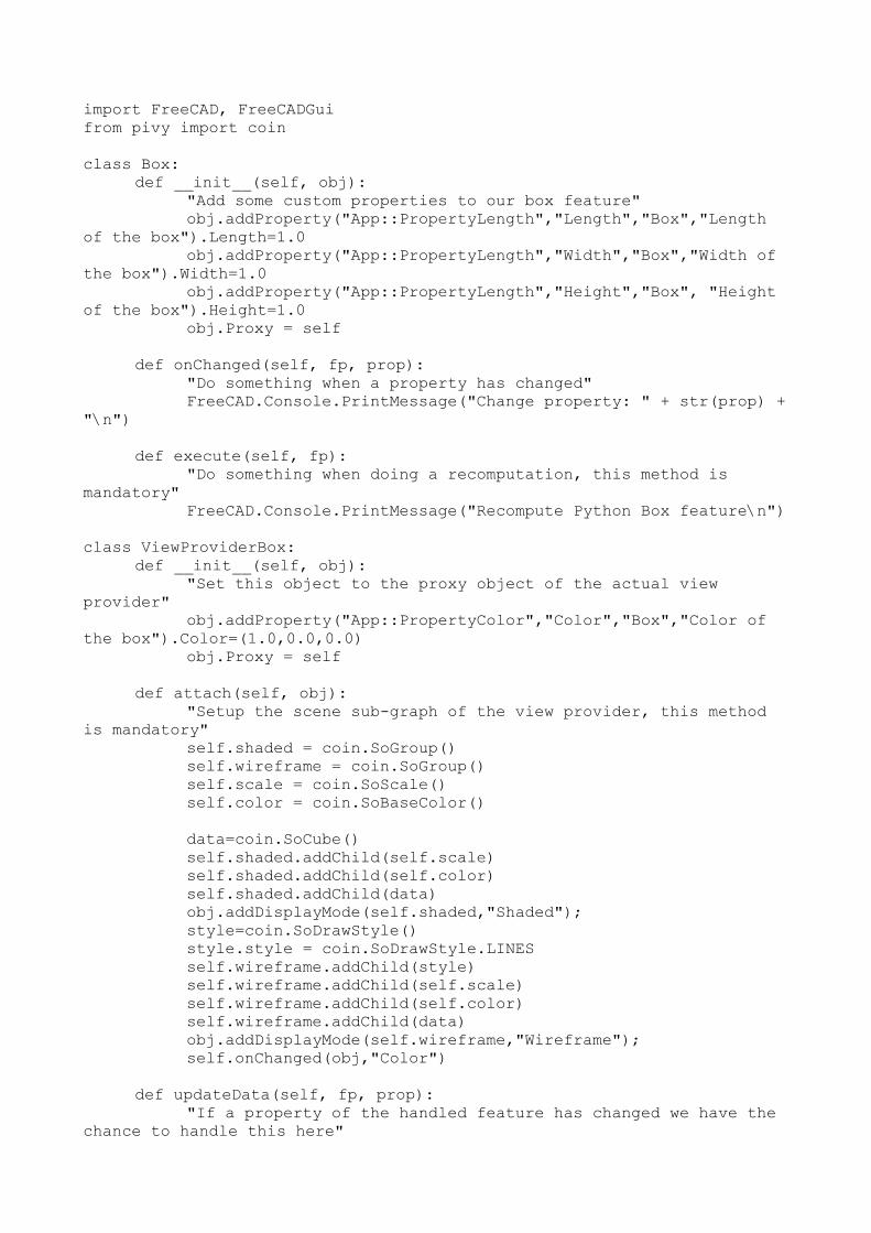
import FreeCAD, FreeCADGuifrom pivy import coin
class Box:def __init__(self, obj):
"Add some custom properties to our box feature"obj.addProperty("App::PropertyLength","Length","Box","Length
of the box").Length=1.0obj.addProperty("App::PropertyLength","Width","Box","Width of
the box").Width=1.0obj.addProperty("App::PropertyLength","Height","Box", "Height
of the box").Height=1.0obj.Proxy = self
def onChanged(self, fp, prop):"Do something when a property has changed"FreeCAD.Console.PrintMessage("Change property: " + str(prop) +
"\n")
def execute(self, fp):"Do something when doing a recomputation, this method is
mandatory"FreeCAD.Console.PrintMessage("Recompute Python Box feature\n")
class ViewProviderBox:
def __init__(self, obj):"Set this object to the proxy object of the actual view
provider"obj.addProperty("App::PropertyColor","Color","Box","Color of
the box").Color=(1.0,0.0,0.0)obj.Proxy = self
def attach(self, obj):
"Setup the scene sub-graph of the view provider, this method is mandatory"
self.shaded = coin.SoGroup()self.wireframe = coin.SoGroup()self.scale = coin.SoScale()self.color = coin.SoBaseColor()
data=coin.SoCube()self.shaded.addChild(self.scale)self.shaded.addChild(self.color)self.shaded.addChild(data)obj.addDisplayMode(self.shaded,"Shaded");style=coin.SoDrawStyle()style.style = coin.SoDrawStyle.LINESself.wireframe.addChild(style)self.wireframe.addChild(self.scale)self.wireframe.addChild(self.color)self.wireframe.addChild(data)obj.addDisplayMode(self.wireframe,"Wireframe");self.onChanged(obj,"Color")
def updateData(self, fp, prop):
"If a property of the handled feature has changed we have the chance to handle this here"

# fp is the handled feature, prop is the name of the property that has changed
l = fp.getPropertyByName("Length")w = fp.getPropertyByName("Width")h = fp.getPropertyByName("Height")self.scale.scaleFactor.setValue(l,w,h)pass
def getDisplayModes(self,obj):
"Return a list of display modes."modes=[]modes.append("Shaded")modes.append("Wireframe")return modes
def getDefaultDisplayMode(self):
"Return the name of the default display mode. It must be defined in getDisplayModes."
return "Shaded"
def setDisplayMode(self,mode):"Map the display mode defined in attach with those defined in
getDisplayModes.\ Since they have the same names nothing needs to be done. This method is optional"
return mode
def onChanged(self, vp, prop):"Here we can do something when a single property got changed"FreeCAD.Console.PrintMessage("Change property: " + str(prop) +
"\n")if prop == "Color":
c = vp.getPropertyByName("Color")self.color.rgb.setValue(c[0],c[1],c[2])
def getIcon(self):
"Return the icon in XPM format which will appear in the tree view. This method is\ optional and if not defined a default icon is shown."
return """/* XPM */static const char * ViewProviderBox_xpm[] = {"16 16 6 1"," c None",". c #141010","+ c #615BD2","@ c #C39D55","# c #000000","$ c #57C355"," ........"," ......++..+.."," .@@@@.++..++."," .@@@@.++..++."," .@@ .++++++."," ..@@ .++..++.","###@@@@ .++..++.","##$.@@$#.++++++.","#$#$.$$$........",

"#$$####### ","#$$#$$$$$# ","#$$#$$$$$# ","#$$#$$$$$# "," #$#$$$$$# "," ##$$$$$# "," ####### "};"""
def __getstate__(self):
"When saving the document this object gets stored using Python's json module.\ Since we have some un-serializable parts here -- the Coinstuff -- we must define this method\ to return a tuple of all serializable objects or None."
return None
def __setstate__(self,state):"When restoring the serialized object from document we have
the chance to set some internals here.\ Since no data were serialized nothing needs to be done here."
return None def makeBox():
FreeCAD.newDocument()a=FreeCAD.ActiveDocument.addObject("App::FeaturePython","Box")Box(a)
ViewProviderBox(a.ViewObject)
Available properties
Properties are the true building stones of FeaturePython objects. Through them, the user will be ableto interact and modify your object. After creating a new FeaturePython object in your document ( obj=FreeCAD.ActiveDocument.addObject("App::FeaturePython","Box") ), you can get a list of the available properties by issuing:
obj.supportedProperties()
You will get a list of available properties:
App::PropertyBoolApp::PropertyFloatApp::PropertyFloatListApp::PropertyFloatConstraintApp::PropertyAngleApp::PropertyDistanceApp::PropertyIntegerApp::PropertyIntegerConstraintApp::PropertyPercentApp::PropertyEnumeration

App::PropertyIntegerListApp::PropertyStringApp::PropertyStringListApp::PropertyLinkApp::PropertyLinkListApp::PropertyMatrixApp::PropertyVectorApp::PropertyVectorListApp::PropertyPlacementApp::PropertyPlacementLinkApp::PropertyColorApp::PropertyColorListApp::PropertyMaterialApp::PropertyPathApp::PropertyFileApp::PropertyFileIncludedPart::PropertyPartShapePart::PropertyFilletContourPart::PropertyCircle
When adding properties to your custom objects, take care of this:
Do not use characters "<" or ">" in the properties descriptions (that would break the xml pieces in the .fcstd file)
Properties are stored alphabetically in a .fcstd file. If you have a shape in your properties, any property whose name comes after "Shape" in alphabetic order, will be loaded AFTER the shape, which can cause strange behaviours.
Property Type
By default the properties can be updated. It is possible to make the properties read-only, for instancein the case one wants to show the result of a method. It is also possible to hide the property. The property type can be set using
obj.setEditorMode("MyPropertyName", mode)
where mode is a short int that can be set to:
0 -- default mode, read and write
1 -- read-only
2 -- hidden

Other more complex example
This example makes use of the Part Module to create an octahedron, then creates its coin representation with pivy.
First is the Document object itself:
import FreeCAD, FreeCADGui, Part
class Octahedron: def __init__(self, obj): "Add some custom properties to our box feature" obj.addProperty("App::PropertyLength","Length","Octahedron","Length of the octahedron").Length=1.0 obj.addProperty("App::PropertyLength","Width","Octahedron","Width of the octahedron").Width=1.0 obj.addProperty("App::PropertyLength","Height","Octahedron", "Height of the octahedron").Height=1.0 obj.addProperty("Part::PropertyPartShape","Shape","Octahedron", "Shape of the octahedron") obj.Proxy = self
def execute(self, fp): # Define six vetices for the shape v1 = FreeCAD.Vector(0,0,0) v2 = FreeCAD.Vector(fp.Length,0,0) v3 = FreeCAD.Vector(0,fp.Width,0) v4 = FreeCAD.Vector(fp.Length,fp.Width,0) v5 = FreeCAD.Vector(fp.Length/2,fp.Width/2,fp.Height/2) v6 = FreeCAD.Vector(fp.Length/2,fp.Width/2,-fp.Height/2) # Make the wires/faces f1 = self.make_face(v1,v2,v5) f2 = self.make_face(v2,v4,v5) f3 = self.make_face(v4,v3,v5) f4 = self.make_face(v3,v1,v5) f5 = self.make_face(v2,v1,v6) f6 = self.make_face(v4,v2,v6) f7 = self.make_face(v3,v4,v6) f8 = self.make_face(v1,v3,v6) shell=Part.makeShell([f1,f2,f3,f4,f5,f6,f7,f8]) solid=Part.makeSolid(shell) fp.Shape = solid
# helper mehod to create the faces def make_face(self,v1,v2,v3): wire = Part.makePolygon([v1,v2,v3,v1]) face = Part.Face(wire) return face
Then, we have the view provider object, responsible for showing the object in the 3D scene:

class ViewProviderOctahedron: def __init__(self, obj): "Set this object to the proxy object of the actual view provider" obj.addProperty("App::PropertyColor","Color","Octahedron","Colorof the octahedron").Color=(1.0,0.0,0.0) obj.Proxy = self
def attach(self, obj): "Setup the scene sub-graph of the view provider, this method is mandatory" self.shaded = coin.SoGroup() self.wireframe = coin.SoGroup() self.scale = coin.SoScale() self.color = coin.SoBaseColor()
self.data=coin.SoCoordinate3() self.face=coin.SoIndexedLineSet()
self.shaded.addChild(self.scale) self.shaded.addChild(self.color) self.shaded.addChild(self.data) self.shaded.addChild(self.face) obj.addDisplayMode(self.shaded,"Shaded"); style=coin.SoDrawStyle() style.style = coin.SoDrawStyle.LINES self.wireframe.addChild(style) self.wireframe.addChild(self.scale) self.wireframe.addChild(self.color) self.wireframe.addChild(self.data) self.wireframe.addChild(self.face) obj.addDisplayMode(self.wireframe,"Wireframe"); self.onChanged(obj,"Color")
def updateData(self, fp, prop): "If a property of the handled feature has changed we have the chance to handle this here" # fp is the handled feature, prop is the name of the property that has changed if prop == "Shape": s = fp.getPropertyByName("Shape") self.data.point.setNum(6) cnt=0 for i in s.Vertexes: self.data.point.set1Value(cnt,i.X,i.Y,i.Z) cnt=cnt+1 self.face.coordIndex.set1Value(0,0) self.face.coordIndex.set1Value(1,1) self.face.coordIndex.set1Value(2,2) self.face.coordIndex.set1Value(3,-1)
self.face.coordIndex.set1Value(4,1) self.face.coordIndex.set1Value(5,3) self.face.coordIndex.set1Value(6,2) self.face.coordIndex.set1Value(7,-1)

self.face.coordIndex.set1Value(8,3) self.face.coordIndex.set1Value(9,4) self.face.coordIndex.set1Value(10,2) self.face.coordIndex.set1Value(11,-1)
self.face.coordIndex.set1Value(12,4) self.face.coordIndex.set1Value(13,0) self.face.coordIndex.set1Value(14,2) self.face.coordIndex.set1Value(15,-1)
self.face.coordIndex.set1Value(16,1) self.face.coordIndex.set1Value(17,0) self.face.coordIndex.set1Value(18,5) self.face.coordIndex.set1Value(19,-1)
self.face.coordIndex.set1Value(20,3) self.face.coordIndex.set1Value(21,1) self.face.coordIndex.set1Value(22,5) self.face.coordIndex.set1Value(23,-1)
self.face.coordIndex.set1Value(24,4) self.face.coordIndex.set1Value(25,3) self.face.coordIndex.set1Value(26,5) self.face.coordIndex.set1Value(27,-1)
self.face.coordIndex.set1Value(28,0) self.face.coordIndex.set1Value(29,4) self.face.coordIndex.set1Value(30,5) self.face.coordIndex.set1Value(31,-1)
def getDisplayModes(self,obj): "Return a list of display modes." modes=[] modes.append("Shaded") modes.append("Wireframe") return modes
def getDefaultDisplayMode(self): "Return the name of the default display mode. It must be definedin getDisplayModes." return "Shaded"
def setDisplayMode(self,mode): return mode
def onChanged(self, vp, prop): "Here we can do something when a single property got changed" FreeCAD.Console.PrintMessage("Change property: " + str(prop) + "\n") if prop == "Color": c = vp.getPropertyByName("Color") self.color.rgb.setValue(c[0],c[1],c[2])
def getIcon(self): return """ /* XPM */ static const char * ViewProviderBox_xpm[] = {

"16 16 6 1", " c None", ". c #141010", "+ c #615BD2", "@ c #C39D55", "# c #000000", "$ c #57C355", " ........", " ......++..+..", " .@@@@.++..++.", " .@@@@.++..++.", " .@@ .++++++.", " ..@@ .++..++.", "###@@@@ .++..++.", "##$.@@$#.++++++.", "#$#$.$$$........", "#$$####### ", "#$$#$$$$$# ", "#$$#$$$$$# ", "#$$#$$$$$# ", " #$#$$$$$# ", " ##$$$$$# ", " ####### "}; """
def __getstate__(self): return None
def __setstate__(self,state): return None
Finally, once our object and its viewobject are defined, we just need to call them:
FreeCAD.newDocument() a=FreeCAD.ActiveDocument.addObject("App::FeaturePython","Octahedron") Octahedron(a) ViewProviderOctahedron(a.ViewObject)
Making objects selectable
If you want to make your object selectable, or at least part of it, by clicking on it in the viewport, you must include its coin geometry inside a SoFCSelection node. If your object has complex representation, with widgets, annotations, etc, you might want to include only a part of it in a SoFCSelection. Everything that is a SoFCSelection is constantly scanned by FreeCAD to detect selection/preselection, so it makes sense try not to overload it with unneeded scanning. This is what you would do to include a self.face from the example above:
selectionNode = coin.SoType.fromName("SoFCSelection").createInstance()selectionNode.documentName.setValue(FreeCAD.ActiveDocument.Name)selectionNode.objectName.setValue(obj.Object.Name) # here obj is the ViewObject, we need its associated App ObjectselectionNode.subElementName.setValue("Face")

selectNode.addChild(self.face)...self.shaded.addChild(selectionNode)self.wireframe.addChild(selectionNode)
Simply, you create a SoFCSelection node, then you add your geometry nodes to it, then you add it to your main node, instead of adding your geometry nodes directly.
Working with simple shapes
If your parametric object simply outputs a shape, you don't need to use a view provider object. The shape will be displayed using FreeCAD's standard shape representation:
class Line: def __init__(self, obj): "App two point properties" obj.addProperty("App::PropertyVector","p1","Line","Start point") obj.addProperty("App::PropertyVector","p2","Line","End point").p2=FreeCAD.Vector(1,0,0) obj.Proxy = self
def execute(self, fp): "Print a short message when doing a recomputation, this method ismandatory" fp.Shape = Part.makeLine(fp.p1,fp.p2)
a=FreeCAD.ActiveDocument.addObject("Part::FeaturePython","Line")Line(a)a.ViewObject.Proxy=0 # just set it to something different from None (thisassignment is needed to run an internal notification)FreeCAD.ActiveDocument.recompute()

Embedding FreeCAD
FreeCAD has the amazing ability to be importable as a python module in other programs or in a standalone python console, together with all its modules and components. It's even possible to import the FreeCAD GUI as python module -- with some restrictions, however.
Using FreeCAD without GUI
One first, direct, easy and useful application you can make of this is to import FreeCAD documents into your program. In the following example, we'll import the Part geometry of a FreeCAD document into blender. Here is the complete script. I hope you'll be impressed by its simplicity:
FREECADPATH = '/opt/FreeCAD/lib' # path to your FreeCAD.so or FreeCAD.dllfileimport Blender, syssys.path.append(FREECADPATH)
def import_fcstd(filename): try: import FreeCAD except ValueError: Blender.Draw.PupMenu('Error%t|FreeCAD library not found. Please check the FREECADPATH variable in the import script is correct') else: scene = Blender.Scene.GetCurrent() import Part doc = FreeCAD.open(filename) objects = doc.Objects for ob in objects: if ob.Type[:4] == 'Part': shape = ob.Shape if shape.Faces: mesh = Blender.Mesh.New() rawdata = shape.tessellate(1) for v in rawdata[0]: mesh.verts.append((v.x,v.y,v.z)) for f in rawdata[1]: mesh.faces.append.append(f) scene.objects.new(mesh,ob.Name) Blender.Redraw()
def main(): Blender.Window.FileSelector(import_fcstd, 'IMPORT FCSTD', Blender.sys.makename(ext='.fcstd'))
# This lets you import the script without running itif __name__=='__main__': main()
The first, important part is to make sure python will find our FreeCAD library. Once it finds it, all FreeCAD modules such as Part, that we'll use too, will be available automatically. So we simply

take the sys.path variable, which is where python searches for modules, and we append the FreeCAD lib path. This modification is only temporary, and will be lost when we'll close our pythoninterpreter. Another way could be making a link to your FreeCAD library in one of the python search paths. I kept the path in a constant (FREECADPATH) so it'll be easier for another user of thescript to configure it to his own system.
Once we are sure the library is loaded (the try/except sequence), we can now work with FreeCAD, the same way as we would inside FreeCAD's own python interpreter. We open the FreeCAD document that is passed to us by the main() function, and we make a list of its objects. Then, as we choosed only to care about Part geometry, we check if the Type property of each object contains "Part", then we tesselate it.
The tesselation produce a list of vertices and a list of faces defined by vertices indexes. This is perfect, since it is exactly the same way as blender defines meshes. So, our task is ridiculously simple, we just add both lists contents to the verts and faces of a blender mesh. When everything is done, we just redraw the screen, and that's it!
Of course this script is very simple (in fact I made a more advanced here), you might want to extendit, for example importing mesh objects too, or importing Part geometry that has no faces, or import other file formats that FreeCAD can read. You might also want to export geometry to a FreeCAD document, which can be done the same way. You might also want to build a dialog, so the user can choose what to import, etc... The beauty of all this actually lies in the fact that you let FreeCAD do the ground work while presenting its results in the program of your choice.
Using FreeCAD with GUI
From version 4.2 on Qt has the intriguing ability to embed Qt-GUI-dependent plugins into non-Qt host applications and share the host's event loop.
Especially, for FreeCAD this means that it can be imported from within another application with its whole user interface where the host application has full control over FreeCAD, then.
The whole python code to achieve that has only two lines
import FreeCADGui FreeCADGui.showMainWindow()
If the host application is based on Qt then this solution should work on all platforms which Qt supports. However, the host should link the same Qt version as FreeCAD because otherwise you could run into unexpected runtime errors.
For non-Qt applications, however, there are a few limitations you must be aware of. This solution probably doesn't work together with all other toolkits. For Windows it works as long as the host application is directly based on Win32 or any other toolkit that internally uses the Win32 API such as wxWidgets, MFC or WinForms. In order to get it working under X11 the host application must

link the "glib" library.
Note, for any console application this solution of course doesn't work because there is no event looprunning.

Code snippets
This page contains examples, pieces, chunks of FreeCAD python code collected from users experiences and discussions on the forums. Read and use it as a start for your own scripts...
A typical InitGui.py file
Every module must contain, besides your main module file, an InitGui.py file, responsible for inserting the module in the main Gui. This is an example of a simple one.
class ScriptWorkbench (Workbench): MenuText = "Scripts" def Initialize(self): import Scripts # assuming Scripts.py is your module list = ["Script_Cmd"] # That list must contain command names, that can be defined in Scripts.py self.appendToolbar("My Scripts",list) Gui.addWorkbench(ScriptWorkbench())
A typical module file
This is an example of a main module file, containing everything your module does. It is the Scripts.py file invoked by the previous example. You can have all your custom commands here.
import FreeCAD, FreeCADGui
class ScriptCmd: def Activated(self): # Here your write what your ScriptCmd does... FreeCAD.Console.PrintMessage('Hello, World!') def GetResources(self): return {'Pixmap' : 'path_to_an_icon/myicon.png', 'MenuText': 'Short text', 'ToolTip': 'More detailed text'} FreeCADGui.addCommand('Script_Cmd', ScriptCmd())
Import a new filetype
Making an importer for a new filetype in FreeCAD is easy. FreeCAD doesn't consider that you import data in an opened document, but rather that you simply can directly open the new filetype. So what you need to do is to add the new file extension to FreeCAD's list of known extensions, and write the code that will read the file and create the FreeCAD objects you want:
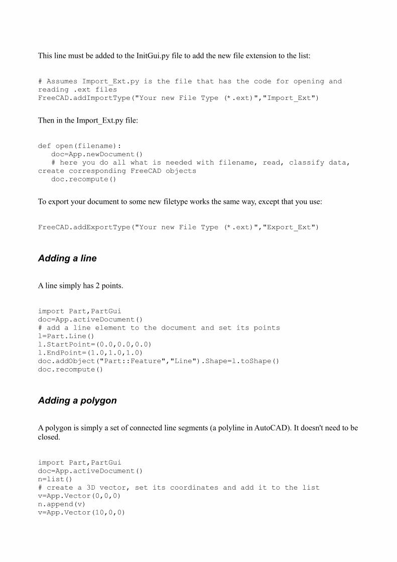
This line must be added to the InitGui.py file to add the new file extension to the list:
# Assumes Import_Ext.py is the file that has the code for opening and reading .ext filesFreeCAD.addImportType("Your new File Type (*.ext)","Import_Ext")
Then in the Import_Ext.py file:
def open(filename): doc=App.newDocument() # here you do all what is needed with filename, read, classify data, create corresponding FreeCAD objects doc.recompute()
To export your document to some new filetype works the same way, except that you use:
FreeCAD.addExportType("Your new File Type (*.ext)","Export_Ext")
Adding a line
A line simply has 2 points.
import Part,PartGui doc=App.activeDocument() # add a line element to the document and set its points l=Part.Line()l.StartPoint=(0.0,0.0,0.0)l.EndPoint=(1.0,1.0,1.0)doc.addObject("Part::Feature","Line").Shape=l.toShape() doc.recompute()
Adding a polygon
A polygon is simply a set of connected line segments (a polyline in AutoCAD). It doesn't need to beclosed.
import Part,PartGui doc=App.activeDocument()n=list() # create a 3D vector, set its coordinates and add it to the list v=App.Vector(0,0,0) n.append(v) v=App.Vector(10,0,0)

n.append(v) #... repeat for all nodes # Create a polygon object and set its nodes p=doc.addObject("Part::Polygon","Polygon") p.Nodes=n doc.recompute()
Adding and removing an object to a group
doc=App.activeDocument() grp=doc.addObject("App::DocumentObjectGroup", "Group") lin=doc.addObject("Part::Feature", "Line")grp.addObject(lin) # adds the lin object to the group grpgrp.removeObject(lin) # removes the lin object from the group grp
Note: You can even add other groups to a group...
Adding a Mesh
import Meshdoc=App.activeDocument()# create a new empty meshm = Mesh.Mesh()# build up box out of 12 facetsm.addFacet(0.0,0.0,0.0, 0.0,0.0,1.0, 0.0,1.0,1.0)m.addFacet(0.0,0.0,0.0, 0.0,1.0,1.0, 0.0,1.0,0.0)m.addFacet(0.0,0.0,0.0, 1.0,0.0,0.0, 1.0,0.0,1.0)m.addFacet(0.0,0.0,0.0, 1.0,0.0,1.0, 0.0,0.0,1.0)m.addFacet(0.0,0.0,0.0, 0.0,1.0,0.0, 1.0,1.0,0.0)m.addFacet(0.0,0.0,0.0, 1.0,1.0,0.0, 1.0,0.0,0.0)m.addFacet(0.0,1.0,0.0, 0.0,1.0,1.0, 1.0,1.0,1.0)m.addFacet(0.0,1.0,0.0, 1.0,1.0,1.0, 1.0,1.0,0.0)m.addFacet(0.0,1.0,1.0, 0.0,0.0,1.0, 1.0,0.0,1.0)m.addFacet(0.0,1.0,1.0, 1.0,0.0,1.0, 1.0,1.0,1.0)m.addFacet(1.0,1.0,0.0, 1.0,1.0,1.0, 1.0,0.0,1.0)m.addFacet(1.0,1.0,0.0, 1.0,0.0,1.0, 1.0,0.0,0.0)# scale to a edge langth of 100m.scale(100.0)# add the mesh to the active documentme=doc.addObject("Mesh::Feature","Cube")me.Mesh=m
Adding an arc or a circle
import Partdoc = App.activeDocument()c = Part.Circle() c.Radius=10.0 f = doc.addObject("Part::Feature", "Circle") # create a document with a circle feature
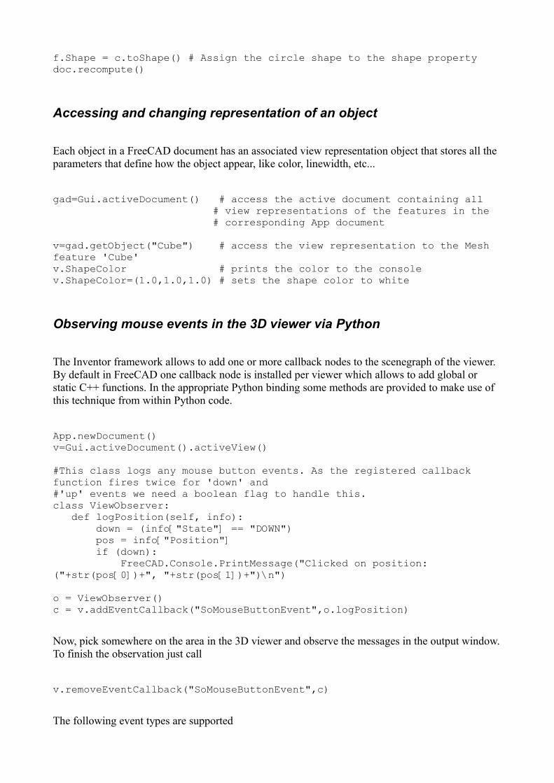
f.Shape = c.toShape() # Assign the circle shape to the shape property doc.recompute()
Accessing and changing representation of an object
Each object in a FreeCAD document has an associated view representation object that stores all the parameters that define how the object appear, like color, linewidth, etc...
gad=Gui.activeDocument() # access the active document containing all # view representations of the features in the # corresponding App document
v=gad.getObject("Cube") # access the view representation to the Mesh feature 'Cube' v.ShapeColor # prints the color to the console v.ShapeColor=(1.0,1.0,1.0) # sets the shape color to white
Observing mouse events in the 3D viewer via Python
The Inventor framework allows to add one or more callback nodes to the scenegraph of the viewer. By default in FreeCAD one callback node is installed per viewer which allows to add global or static C++ functions. In the appropriate Python binding some methods are provided to make use of this technique from within Python code.
App.newDocument()v=Gui.activeDocument().activeView()
#This class logs any mouse button events. As the registered callback function fires twice for 'down' and#'up' events we need a boolean flag to handle this.class ViewObserver: def logPosition(self, info): down = (info["State"] == "DOWN") pos = info["Position"] if (down): FreeCAD.Console.PrintMessage("Clicked on position: ("+str(pos[0])+", "+str(pos[1])+")\n") o = ViewObserver()c = v.addEventCallback("SoMouseButtonEvent",o.logPosition)
Now, pick somewhere on the area in the 3D viewer and observe the messages in the output window.To finish the observation just call
v.removeEventCallback("SoMouseButtonEvent",c)
The following event types are supported

SoEvent -- all kind of events
SoButtonEvent -- all mouse button and key events
SoLocation2Event -- 2D movement events (normally mouse movements)
SoMotion3Event -- 3D movement events (normally spaceball)
SoKeyboardEvent -- key down and up events
SoMouseButtonEvent -- mouse button down and up events
SoSpaceballButtonEvent -- spaceball button down and up events
The Python function that can be registered with addEventCallback() expects a dictionary. Depending on the watched event the dictionary can contain different keys.
For all events it has the keys:
Type -- the name of the event type i.e. SoMouseEvent, SoLocation2Event, ...
Time -- the current time as string
Position -- a tuple of two integers, mouse position
ShiftDown -- a boolean, true if Shift was pressed otherwise false
CtrlDown -- a boolean, true if Ctrl was pressed otherwise false
AltDown -- a boolean, true if Alt was pressed otherwise false
For all button events, i.e. keyboard, mouse or spaceball events
State -- A string 'UP' if the button was up, 'DOWN' if it was down or 'UNKNOWN' for all other cases
For keyboard events:
Key -- a character of the pressed key
For mouse button event
Button -- The pressed button, could be BUTTON1, ..., BUTTON5 or ANY
For spaceball events:
Button -- The pressed button, could be BUTTON1, ..., BUTTON7 or ANY

And finally motion events:
Translation -- a tuple of three floats
Rotation -- a quaternion for the rotation, i.e. a tuple of four floats
Manipulate the scenegraph in Python
It is also possible to get and change the scenegraph in Python, with the 'pivy' module -- a Python binding for Coin.
from pivy.coin import * # load the pivy module
view = Gui.ActiveDocument.ActiveView # get the active viewer
root = view.getSceneGraph() # the root is an SoSeparator node
root.addChild(SoCube())
view.fitAll()
The Python API of pivy is created by using the tool SWIG. As we use in FreeCAD some self-written nodes you cannot create them directly in Python. However, it is possible to create a node by its internal name. An instance of the type 'SoFCSelection' can be created with
type = SoType.fromName("SoFCSelection")
node = type.createInstance()
Adding and removing objects to/from the scenegraph
Adding new nodes to the scenegraph can be done this way. Take care of always adding a SoSeparator to contain the geometry, coordinates and material info of a same object. The following example adds a red line from (0,0,0) to (10,0,0):
from pivy import coinsg = Gui.ActiveDocument.ActiveView.getSceneGraph()co = coin.SoCoordinate3()pts = [[0,0,0],[10,0,0]]co.point.setValues(0,len(pts),pts)ma = coin.SoBaseColor()ma.rgb = (1,0,0)li = coin.SoLineSet()li.numVertices.setValue(2)no = coin.SoSeparator()
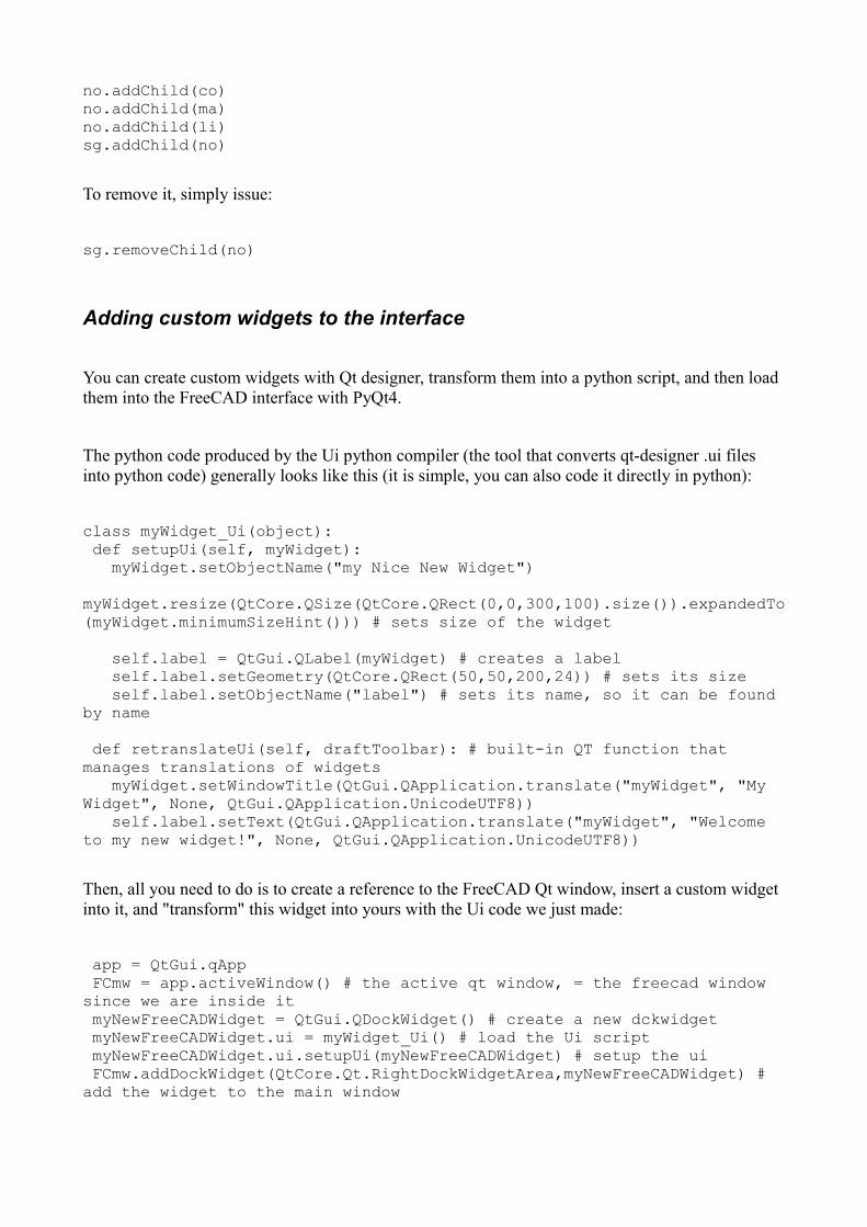
no.addChild(co)no.addChild(ma)no.addChild(li)sg.addChild(no)
To remove it, simply issue:
sg.removeChild(no)
Adding custom widgets to the interface
You can create custom widgets with Qt designer, transform them into a python script, and then load them into the FreeCAD interface with PyQt4.
The python code produced by the Ui python compiler (the tool that converts qt-designer .ui files into python code) generally looks like this (it is simple, you can also code it directly in python):
class myWidget_Ui(object): def setupUi(self, myWidget): myWidget.setObjectName("my Nice New Widget") myWidget.resize(QtCore.QSize(QtCore.QRect(0,0,300,100).size()).expandedTo(myWidget.minimumSizeHint())) # sets size of the widget
self.label = QtGui.QLabel(myWidget) # creates a label self.label.setGeometry(QtCore.QRect(50,50,200,24)) # sets its size self.label.setObjectName("label") # sets its name, so it can be found by name
def retranslateUi(self, draftToolbar): # built-in QT function that manages translations of widgets myWidget.setWindowTitle(QtGui.QApplication.translate("myWidget", "My Widget", None, QtGui.QApplication.UnicodeUTF8)) self.label.setText(QtGui.QApplication.translate("myWidget", "Welcome to my new widget!", None, QtGui.QApplication.UnicodeUTF8))
Then, all you need to do is to create a reference to the FreeCAD Qt window, insert a custom widget into it, and "transform" this widget into yours with the Ui code we just made:
app = QtGui.qApp FCmw = app.activeWindow() # the active qt window, = the freecad window since we are inside it myNewFreeCADWidget = QtGui.QDockWidget() # create a new dckwidget myNewFreeCADWidget.ui = myWidget_Ui() # load the Ui script myNewFreeCADWidget.ui.setupUi(myNewFreeCADWidget) # setup the ui FCmw.addDockWidget(QtCore.Qt.RightDockWidgetArea,myNewFreeCADWidget) # add the widget to the main window

Adding a Tab to the Combo View
The following code allows you to add a tab to the FreeCAD ComboView, besides the "Project" and "Tasks" tabs. It also uses the uic module to load an ui file directly in that tab.
from PyQt4 import QtGui,QtCorefrom PyQt4 import uic#from PySide import QtGui,QtCore
def getMainWindow(): "returns the main window" # using QtGui.qApp.activeWindow() isn't very reliable because if another # widget than the mainwindow is active (e.g. a dialog) the wrong widget is # returned toplevel = QtGui.qApp.topLevelWidgets() for i in toplevel: if i.metaObject().className() == "Gui::MainWindow": return i raise Exception("No main window found")
def getComboView(mw): dw=mw.findChildren(QtGui.QDockWidget) for i in dw: if str(i.objectName()) == "Combo View": return i.findChild(QtGui.QTabWidget) raise Exception("No tab widget found")
mw = getMainWindow()tab = getComboView(getMainWindow())tab2=QtGui.QDialog()tab.addTab(tab2,"A Special Tab")uic.loadUi("/myTaskPanelforTabs.ui",tab2)tab2.show()
#tab.removeTab(2)
Opening a custom webpage
import WebGuiWebGui.openBrowser("http://www.example.com")
Getting the HTML contents of an opened webpage
from PyQt4 import QtGui,QtWebKita = QtGui.qAppmw = a.activeWindow()v = mw.findChild(QtWebKit.QWebFrame)html = unicode(v.toHtml())
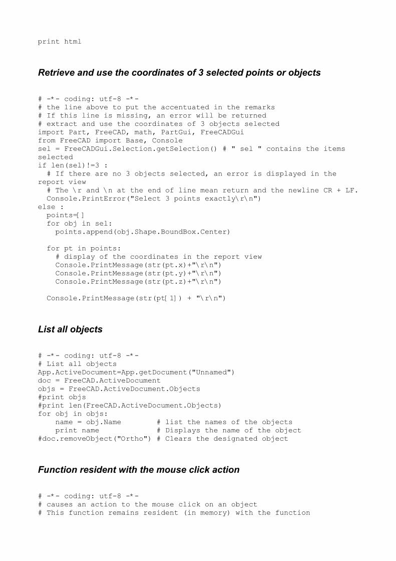
print html
Retrieve and use the coordinates of 3 selected points or objects
# -*- coding: utf-8 -*-# the line above to put the accentuated in the remarks# If this line is missing, an error will be returned# extract and use the coordinates of 3 objects selectedimport Part, FreeCAD, math, PartGui, FreeCADGuifrom FreeCAD import Base, Consolesel = FreeCADGui.Selection.getSelection() # " sel " contains the items selectedif len(sel)!=3 : # If there are no 3 objects selected, an error is displayed in the report view # The \r and \n at the end of line mean return and the newline CR + LF. Console.PrintError("Select 3 points exactly\r\n")else : points=[] for obj in sel: points.append(obj.Shape.BoundBox.Center)
for pt in points: # display of the coordinates in the report view Console.PrintMessage(str(pt.x)+"\r\n") Console.PrintMessage(str(pt.y)+"\r\n") Console.PrintMessage(str(pt.z)+"\r\n")
Console.PrintMessage(str(pt[1]) + "\r\n")
List all objects
# -*- coding: utf-8 -*-# List all objectsApp.ActiveDocument=App.getDocument("Unnamed")doc = FreeCAD.ActiveDocumentobjs = FreeCAD.ActiveDocument.Objects#print objs#print len(FreeCAD.ActiveDocument.Objects)for obj in objs: name = obj.Name # list the names of the objects print name # Displays the name of the object#doc.removeObject("Ortho") # Clears the designated object
Function resident with the mouse click action
# -*- coding: utf-8 -*-# causes an action to the mouse click on an object# This function remains resident (in memory) with the function
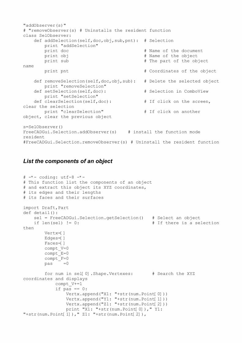
"addObserver(s)"# "removeObserver(s) # Uninstalls the resident functionclass SelObserver: def addSelection(self,doc,obj,sub,pnt): # Selection print "addSelection" print doc # Name of the document print obj # Name of the object print sub # The part of the object name print pnt # Coordinates of the object
def removeSelection(self,doc,obj,sub): # Delete the selected object print "removeSelection" def setSelection(self,doc): # Selection in ComboView print "setSelection" def clearSelection(self,doc): # If click on the screen, clear the selection print "clearSelection" # If click on another object, clear the previous object
s=SelObserver()FreeCADGui.Selection.addObserver(s) # install the function mode resident#FreeCADGui.Selection.removeObserver(s) # Uninstall the resident function
List the components of an object
# -*- coding: utf-8 -*-# This function list the components of an object# and extract this object its XYZ coordinates,# its edges and their lengths# its faces and their surfaces
import Draft,Partdef detail(): sel = FreeCADGui.Selection.getSelection() # Select an object if len(sel) != 0: # If there is a selectionthen Vertx=[] Edges=[] Faces=[] compt_V=0 compt_E=0 compt_F=0 pas =0
for num in sel[0].Shape.Vertexes: # Search the XYZ coordinates and displays compt_V+=1 if pas == 0: Vertx.append("X1: "+str(num.Point[0])) Vertx.append("Y1: "+str(num.Point[1])) Vertx.append("Z1: "+str(num.Point[2])) print "X1: "+str(num.Point[0])," Y1: "+str(num.Point[1])," Z1: "+str(num.Point[2]),

pas=1 else: Vertx.append("X2: "+str(num.Point[0])) Vertx.append("Y2: "+str(num.Point[1])) Vertx.append("Z2: "+str(num.Point[2])) print " X2: "+str(num.Point[0])," Y2: "+str(num.Point[1])," Z2: "+str(num.Point[2]) pas=0 print "Number of Vertex : ", compt_V perimetre = 0.0 EdgesLong = []
for j in enumerate(sel[0].Shape.Edges): # Search the "Edges" and their lengths compt_E+=1 Edges.append("Edge%d" % (j[0]+1)) EdgesLong.append(str(sel[0].Shape.Edges[compt_E-1].Length)) perimetre += (sel[0].Shape.Edges[compt_E-1].Length) # calculates the perimeter print "Edge",str(compt_E)," > ",str(sel[0].Shape.Edges[compt_E-1].Length)# Displays the "Edge" and its length print "Perimeter of the form : ",perimetre
FacesSurf = [] for j in enumerate(sel[0].Shape.Faces): # Search the "Faces" and their surface compt_F+=1 Faces.append("Face%d" % (j[0]+1)) FacesSurf.append(str(sel[0].Shape.Faces[compt_F-1].Area)) print "Face",str(compt_F)," > ",sel[0].Shape.Faces[compt_F-1].Area # Displays 'Face' and its surface print "Surface of the form : ",sel[0].Shape.Area # Displays the total surface of the form
detail()
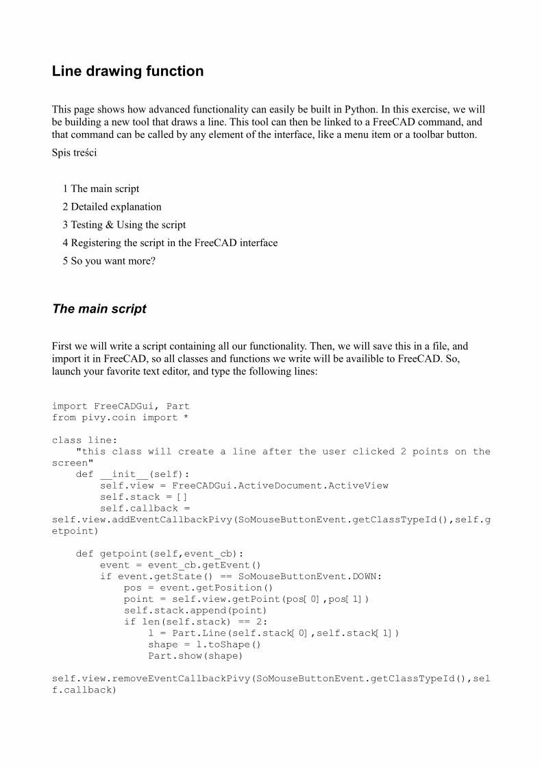
Line drawing function
This page shows how advanced functionality can easily be built in Python. In this exercise, we will be building a new tool that draws a line. This tool can then be linked to a FreeCAD command, and that command can be called by any element of the interface, like a menu item or a toolbar button.
Spis treści
1 The main script
2 Detailed explanation
3 Testing & Using the script
4 Registering the script in the FreeCAD interface
5 So you want more?
The main script
First we will write a script containing all our functionality. Then, we will save this in a file, and import it in FreeCAD, so all classes and functions we write will be availible to FreeCAD. So, launch your favorite text editor, and type the following lines:
import FreeCADGui, Partfrom pivy.coin import *
class line: "this class will create a line after the user clicked 2 points on thescreen" def __init__(self): self.view = FreeCADGui.ActiveDocument.ActiveView self.stack = [] self.callback = self.view.addEventCallbackPivy(SoMouseButtonEvent.getClassTypeId(),self.getpoint)
def getpoint(self,event_cb): event = event_cb.getEvent() if event.getState() == SoMouseButtonEvent.DOWN: pos = event.getPosition() point = self.view.getPoint(pos[0],pos[1]) self.stack.append(point) if len(self.stack) == 2: l = Part.Line(self.stack[0],self.stack[1]) shape = l.toShape() Part.show(shape) self.view.removeEventCallbackPivy(SoMouseButtonEvent.getClassTypeId(),self.callback)

Detailed explanation
import Part, FreeCADGuifrom pivy.coin import *
In Python, when you want to use functions from another module, you need to import it. In our case, we will need functions from the Part Module, for creating the line, and from the Gui module (FreeCADGui), for accessing the 3D view. We also need the complete contents of the coin library, so we can use directly all coin objects like SoMouseButtonEvent, etc...
class line:
Here we define our main class. Why do we use a class and not a function? The reason is that we need our tool to stay "alive" while we are waiting for the user to click on the screen. A function endswhen its task has been done, but an object (a class defines an object) stays alive until it is destroyed.
"this class will create a line after the user clicked 2 points on the screen"
In Python, every class or function can have a description string. This is particularly useful in FreeCAD, because when you'll call that class in the interpreter, the description string will be displayed as a tooltip.
def __init__(self):
Python classes can always contain an __init__ function, which is executed when the class is called to create an object. So, we will put here everything we want to happen when our line tool begins.
self.view = FreeCADGui.ActiveDocument.ActiveView
In a class, you usually want to append self. before a variable name, so it will be easily accessible to all functions inside and outside that class. Here, we will use self.view to access and manipulate the active 3D view.
self.stack = []
Here we create an empty list that will contain the 3D points sent by the getpoint function.
self.callback = self.view.addEventCallbackPivy(SoMouseButtonEvent.getClassTypeId(),self.getpoint)
This is the important part: Since it is actually a coin3D scene, the FreeCAD uses coin callback mechanism, that allows a function to be called everytime a certain scene event happens. In our case,
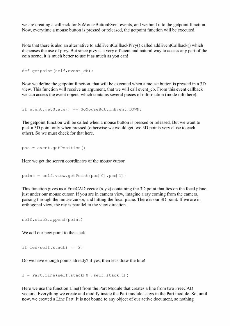
we are creating a callback for SoMouseButtonEvent events, and we bind it to the getpoint function. Now, everytime a mouse button is pressed or released, the getpoint function will be executed.
Note that there is also an alternative to addEventCallbackPivy() called addEventCallback() which dispenses the use of pivy. But since pivy is a very efficient and natural way to access any part of thecoin scene, it is much better to use it as much as you can!
def getpoint(self,event_cb):
Now we define the getpoint function, that will be executed when a mouse button is pressed in a 3D view. This function will receive an argument, that we will call event_cb. From this event callback we can access the event object, which contains several pieces of information (mode info here).
if event.getState() == SoMouseButtonEvent.DOWN:
The getpoint function will be called when a mouse button is pressed or released. But we want to pick a 3D point only when pressed (otherwise we would get two 3D points very close to each other). So we must check for that here.
pos = event.getPosition()
Here we get the screen coordinates of the mouse cursor
point = self.view.getPoint(pos[0],pos[1])
This function gives us a FreeCAD vector (x,y,z) containing the 3D point that lies on the focal plane,just under our mouse cursor. If you are in camera view, imagine a ray coming from the camera, passing through the mouse cursor, and hitting the focal plane. There is our 3D point. If we are in orthogonal view, the ray is parallel to the view direction.
self.stack.append(point)
We add our new point to the stack
if len(self.stack) == 2:
Do we have enough points already? if yes, then let's draw the line!
l = Part.Line(self.stack[0],self.stack[1])
Here we use the function Line() from the Part Module that creates a line from two FreeCAD vectors. Everything we create and modify inside the Part module, stays in the Part module. So, untilnow, we created a Line Part. It is not bound to any object of our active document, so nothing
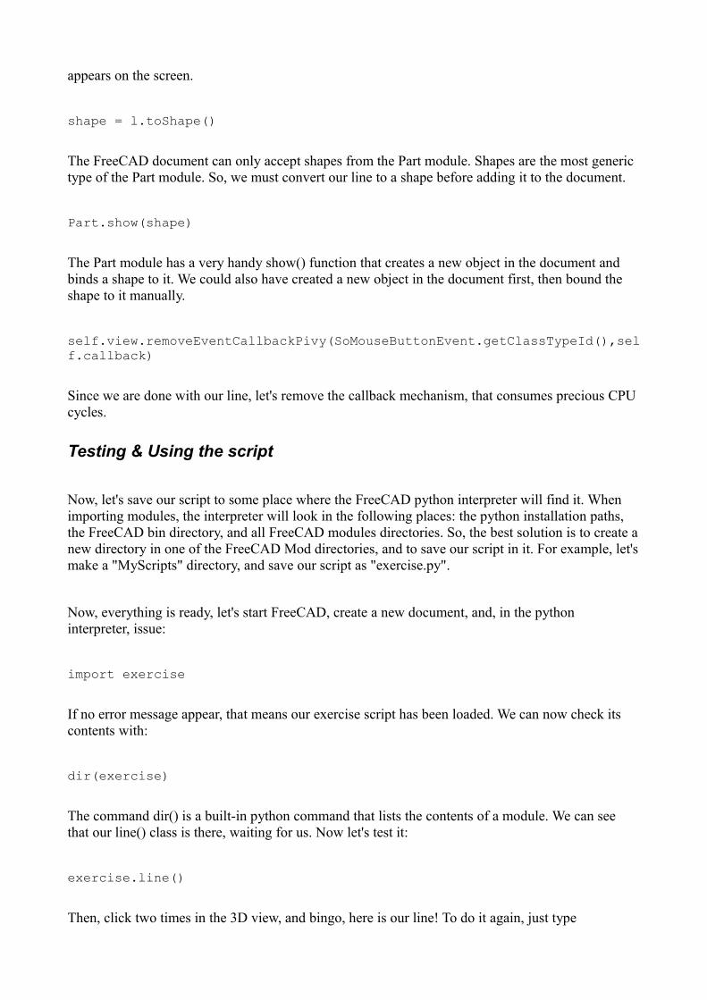
appears on the screen.
shape = l.toShape()
The FreeCAD document can only accept shapes from the Part module. Shapes are the most generic type of the Part module. So, we must convert our line to a shape before adding it to the document.
Part.show(shape)
The Part module has a very handy show() function that creates a new object in the document and binds a shape to it. We could also have created a new object in the document first, then bound the shape to it manually.
self.view.removeEventCallbackPivy(SoMouseButtonEvent.getClassTypeId(),self.callback)
Since we are done with our line, let's remove the callback mechanism, that consumes precious CPU cycles.
Testing & Using the script
Now, let's save our script to some place where the FreeCAD python interpreter will find it. When importing modules, the interpreter will look in the following places: the python installation paths, the FreeCAD bin directory, and all FreeCAD modules directories. So, the best solution is to create anew directory in one of the FreeCAD Mod directories, and to save our script in it. For example, let'smake a "MyScripts" directory, and save our script as "exercise.py".
Now, everything is ready, let's start FreeCAD, create a new document, and, in the python interpreter, issue:
import exercise
If no error message appear, that means our exercise script has been loaded. We can now check its contents with:
dir(exercise)
The command dir() is a built-in python command that lists the contents of a module. We can see that our line() class is there, waiting for us. Now let's test it:
exercise.line()
Then, click two times in the 3D view, and bingo, here is our line! To do it again, just type
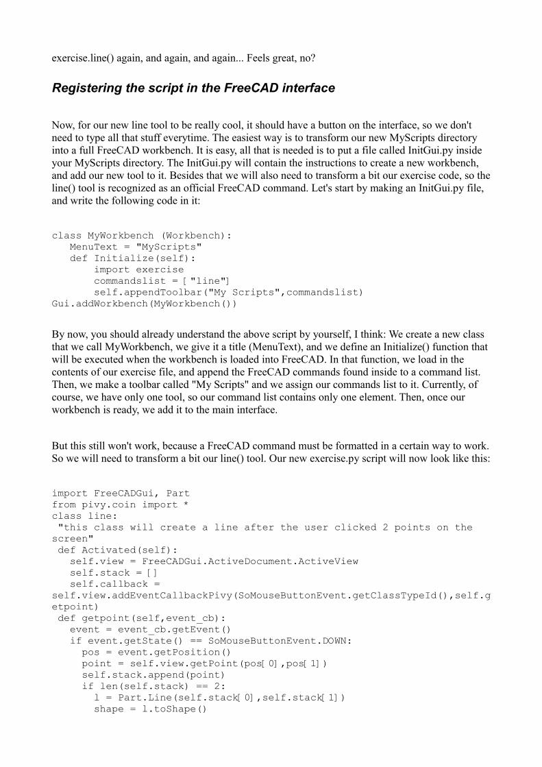
exercise.line() again, and again, and again... Feels great, no?
Registering the script in the FreeCAD interface
Now, for our new line tool to be really cool, it should have a button on the interface, so we don't need to type all that stuff everytime. The easiest way is to transform our new MyScripts directory into a full FreeCAD workbench. It is easy, all that is needed is to put a file called InitGui.py inside your MyScripts directory. The InitGui.py will contain the instructions to create a new workbench, and add our new tool to it. Besides that we will also need to transform a bit our exercise code, so theline() tool is recognized as an official FreeCAD command. Let's start by making an InitGui.py file, and write the following code in it:
class MyWorkbench (Workbench): MenuText = "MyScripts" def Initialize(self): import exercise commandslist = ["line"] self.appendToolbar("My Scripts",commandslist)Gui.addWorkbench(MyWorkbench())
By now, you should already understand the above script by yourself, I think: We create a new class that we call MyWorkbench, we give it a title (MenuText), and we define an Initialize() function that will be executed when the workbench is loaded into FreeCAD. In that function, we load in the contents of our exercise file, and append the FreeCAD commands found inside to a command list. Then, we make a toolbar called "My Scripts" and we assign our commands list to it. Currently, of course, we have only one tool, so our command list contains only one element. Then, once our workbench is ready, we add it to the main interface.
But this still won't work, because a FreeCAD command must be formatted in a certain way to work.So we will need to transform a bit our line() tool. Our new exercise.py script will now look like this:
import FreeCADGui, Partfrom pivy.coin import *class line: "this class will create a line after the user clicked 2 points on the screen" def Activated(self): self.view = FreeCADGui.ActiveDocument.ActiveView self.stack = [] self.callback = self.view.addEventCallbackPivy(SoMouseButtonEvent.getClassTypeId(),self.getpoint) def getpoint(self,event_cb): event = event_cb.getEvent() if event.getState() == SoMouseButtonEvent.DOWN: pos = event.getPosition() point = self.view.getPoint(pos[0],pos[1]) self.stack.append(point) if len(self.stack) == 2: l = Part.Line(self.stack[0],self.stack[1]) shape = l.toShape()
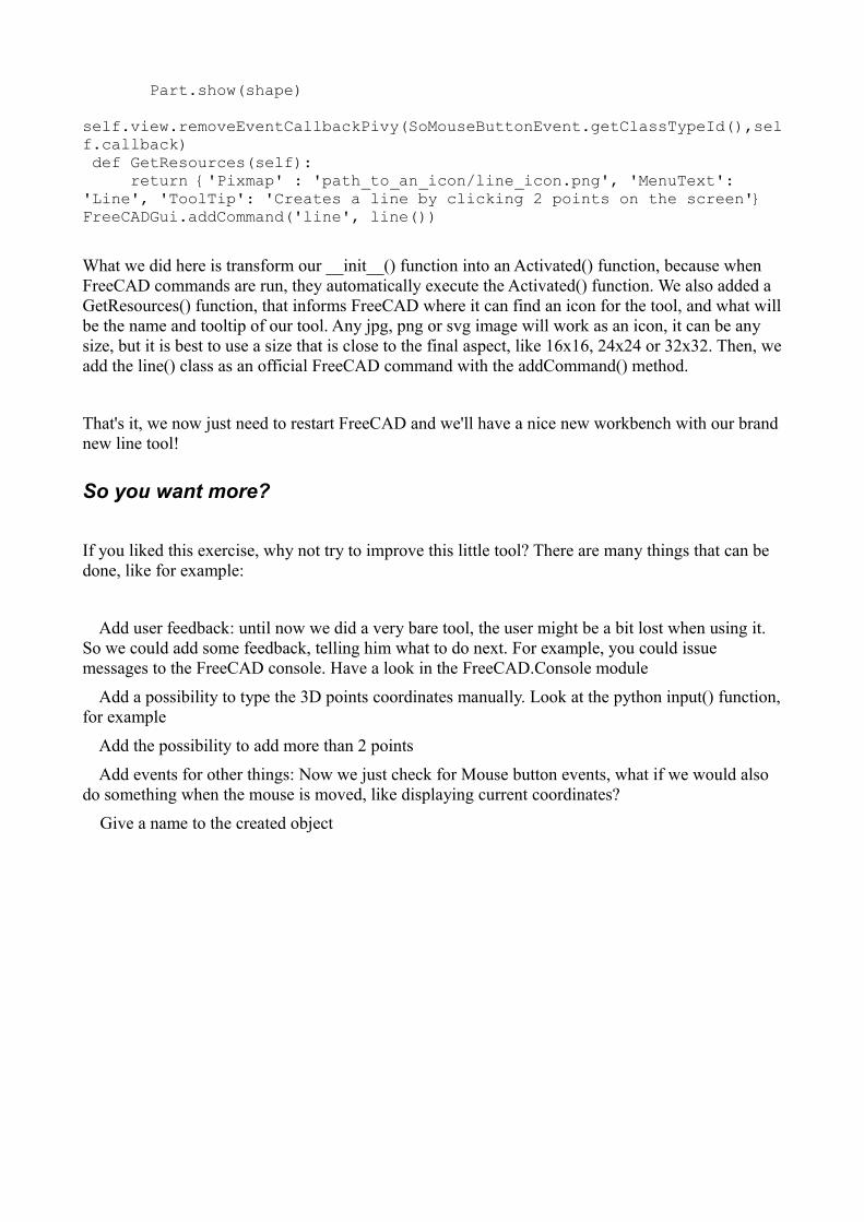
Part.show(shape) self.view.removeEventCallbackPivy(SoMouseButtonEvent.getClassTypeId(),self.callback) def GetResources(self): return {'Pixmap' : 'path_to_an_icon/line_icon.png', 'MenuText': 'Line', 'ToolTip': 'Creates a line by clicking 2 points on the screen'} FreeCADGui.addCommand('line', line())
What we did here is transform our __init__() function into an Activated() function, because when FreeCAD commands are run, they automatically execute the Activated() function. We also added a GetResources() function, that informs FreeCAD where it can find an icon for the tool, and what willbe the name and tooltip of our tool. Any jpg, png or svg image will work as an icon, it can be any size, but it is best to use a size that is close to the final aspect, like 16x16, 24x24 or 32x32. Then, weadd the line() class as an official FreeCAD command with the addCommand() method.
That's it, we now just need to restart FreeCAD and we'll have a nice new workbench with our brandnew line tool!
So you want more?
If you liked this exercise, why not try to improve this little tool? There are many things that can be done, like for example:
Add user feedback: until now we did a very bare tool, the user might be a bit lost when using it. So we could add some feedback, telling him what to do next. For example, you could issue messages to the FreeCAD console. Have a look in the FreeCAD.Console module
Add a possibility to type the 3D points coordinates manually. Look at the python input() function,for example
Add the possibility to add more than 2 points
Add events for other things: Now we just check for Mouse button events, what if we would also do something when the mouse is moved, like displaying current coordinates?
Give a name to the created object