exteriors - james hardie industries · 2.8mm x 65mm long ring shank nail or 75 x 2.8mm d or round...
TRANSCRIPT

EXTERIORS
Scyon™ Matrix™ Cladding
Installation Guide
Australia May 2019
Make sure your information is up to date. When specifying or installing James Hardie™ products, ensure that you have the current technical information and guides. If in doubt, or you need more information, visit www.jameshardie.com.au or Ask James Hardie™ on 13 11 03. Certificate CM40224

IMPORTANT NOTES 1. Failure to install, finish or maintain this product in accordance with applicable building codes, regulations,
standards and James Hardie’s written application instructions may lead to personal injury, affect system performance, violate local building codes, and void James Hardie’s product warranty.
2. All warranties, conditions, liabilities (direct, indirect or consequential) and obligations whether arising in contract, tort or otherwise other than those specified in James Hardie’s product warranty are excluded to the fullest extent allowed by law. For James Hardie’s product warranty information and disclaimers about the information in this guide, refer to www.jameshardie.com.au.
3. The builder must ensure the product meets aesthetic requirements before installation. James Hardie™ will not be responsible for rectifying aesthetic surface variations following installation.
4. Make sure your information is up to date. When specifying or installing James Hardie™ products, ensure you have the current guide. If in doubt, or you need more information, visit www.jameshardie.com.au or Ask James Hardie™ on 13 11 03.
All dimensions and masses provided are approximate only and subject to manufacturing tolerances.Masses are based on equilibrium moisture content of product.
MATRIX™ SHEET AND SCYON™ CAVITY TRIM PRODUCT SIZE
WARNINGDO NOT BREATHE DUST AND CUT ONLY IN WELL VENTILATED AREAJames Hardie™ products contain sand, a source of respirable crystalline silica which is considered by some international authorities to be a cause of cancer from some occupational sources. Breathing excessive amounts of respirable silica dust can also cause a disabling and potentially fatal lung disease called silicosis, and has been linked with other diseases. Some studies suggest smoking may increase these risks. During installation or handling:(1) work in outdoor areas with ample ventilation;(2) minimise dust when cutting by using either ‘score and snap’ knife, fibre cement shears or, where not feasible, use a HardieBlade™ Saw Blade (or equivalent) and dust-reducing circular saw attached to an appropriate, well maintained, filtered vacuum; (3) warn others in the immediate area to avoid breathing dust; (4) wear a properly-fitted, approved dust mask or respirator (e.g. P1 or P2) in accordance with applicable government regulations and manufacturer instructions to further limit respirable silica exposures. During clean-up use a vacuum and filter, both of which are well maintained and appropriate for capturing fine (respirable) dust. Alternatively, use wet clean-up methods - never dry sweep. For further information, refer to our installation instructions and Safety Data Sheets available at www.jameshardie.com.au. FAILURE TO ADHERE TO OUR WARNINGS, SAFETY DATA SHEETS, AND INSTALLATION INSTRUCTIONS MAY LEAD TO SERIOUS PERSONAL INJURY OR DEATH.
CUTTING OUTDOORS 1. Position cutting station so wind will blow dust away from the user or others in working area. 2. Position the cutting station in a well-ventilated area. Use a dust reducing circular saw equipped with HardieBlade™ Saw Blade or comparable fibre cement blade and well maintained vacuum and filter appropriate for capturing fine (respirable) dust.
CUTTING INDOORS n Cut only using score and snap, hand guillotine or fibreshears (manual, electric or pneumatic). n Position cutting station in a well-ventilated area.
DRILLING/OTHER MACHINING When drilling or machining you should always wear a P1 or P2 dust mask and warn others in the immediate area.
IMPORTANT NOTES 1. For maximum protection (lowest respirable dust production) James Hardie recommends always using best practice cutting methods where feasible. 2. NEVER use a power saw indoors. 3. ALWAYS use a circular saw blade that carries the HardieBlade™ logo or is of at least comparable performance. 4. NEVER dry sweep - Use wet suppression or appropriate vacuum and filter. 5. NEVER use grinders. 6. ALWAYS follow tool manufacturers’ safety recommendations.
DUST MASKS AND RESPIRATORS James Hardie recommends the use of P2 respirators as best practice. As a minimum, an AS/NZS1716 P1 respirator must be used when doing any activity that may create dust. For more extensive guidance and options for selecting respirators for workplaces please refer to Australian/New Zealand Standard 1715:2009 “Selection, Use and Maintenance of Respiratory Protective Equipment”. P1 or P2 respirators should be used in conjunction with the above cutting practices to minimise dust exposure. For further information, refer to Safety Data Sheet (SDS) available at www.jameshardie.com.au. If concern still exists about exposure levels or you do not comply with the above practices, you should always consult a qualified industrial hygienist or contact James Hardie for further information.
JAMES HARDIE RECOMMENDED SAFE WORKING PRACTICES
PRODUCT LENGTH (mm) WIDTH (mm) THICKNESS (mm) MASS (kg)MATRIX™ PANEL 1190 1190 8 18
2390 590 8 181790 890 8 202990 1190 8 45
SCYON™ CAVITY TRIM
2450 70 19 3.4
ACCESSORIES / TOOLS SUPPLIED BY JAMES HARDIE
Installation Guide
Scyon™ cavity trim Made in Australia & New Zealand
Matrix™ panels Made in Australia
SCYON™ MATRIX™ CLADDING INSTALLATION GUIDE PAGE 2 OF 8
ACCESSORIES DESCRIPTION
James Hardie™ Base Coat. 4kg tub & 15kg bag A water-resistant base coat compound used to flush over epoxy filled countersunk fasteners. 4kg tub 4 per box Part No. 305535. 15kg bag 1 each Part No. 304491
James Hardie™ Joint Sealant. 300ML cartridge A general purpose, paintable, exterior grade polyurethane joint sealant. 20 per box. Part No. 305534.
James Hardie™ Facade Washers Façade washers used for exposed fastener fixing with Scyon™ Matrix™ cladding. 1000 per bag. Part No. 305565
12mm Double Sided Bonding Tape Alternate method to fix the lower part of the JHbacking strip to the back of the Matrix panel athorizontal joints .33m long roll Part No.305673
HardieWrap™ weather barrier A non-perforated, highly breathable and reflective safe-glare weather barrier designed to be used behind Scyon™ external cladding products to help protect the building. For alternate products, please refer to HardieWrap™ weather barrier section (p.2). Unit size 2750mm x 30,000mm. 1 each. Part No. 305664
TOOLS
HardieBlade™ Saw Blade. 185mm diameter A 185mm diameter poly-diamond blade for fast and clean cutting of James Hardie™ fibre cement. 1 each. Part No. 300660
ACCESSORIES DESCRIPTION
James Hardie™ Backing Strip. 1190mm, 2390mm, 2990mm long A weather seal at horizontal panel joints for use with Scyon™ Matrix™ cladding. 10 per pack. 1190mm Part No. 305557. 2390mm Part No. 305558. 2990mm Part No. 305559.
James Hardie™ 18mm PVC Cavity Vent Strip. 3,000mm Long A perforated PVC extrusion used at the bottom of walls behind Scyon™ Matrix™
cladding. 25 per pack. Part No. 305555
James Hardie™ 9mm Aluminium External Corner. 3,000mm long A ready to paint aluminium extrusion, to be used with Scyon™ Matrix™ cladding, Scyon Axon™ cladding and EasyLap™ panel at external corner junctions to conceal the board edge. 5 per pack. Part No. 305521
HardieEdge™ Trim An architectural slab edge solution fabricated from high-quality powder coated aluminium. Base Trim unit size: 3950mm. Also available: Base Trim 4 per pack. Part No. 305911Base Trim Jointer 12 per pack. Part No. 305912Internal Corner 4 per pack. Part No. 305913External Corner 4 per pack. Part No. 305914
HardieDrive™ Screw 41mm Long* A class 3 self-tapping wing-tipped screw for fastening to 0.5mm to 1.6mm BMT light gauge steel frames. 1000 per box. Part No. 305984
HardieDrive™ Collated Screw 41mm long* A class 3 self-tapping wing-tipped screw for fastening to 0.5mm to 1.6mm BMT light gauge steel frames. Suitable for use in most auto feed screw guns. 1000 per box. Part No. 305982
COMPONENTS NOT SUPPLIED BY JAMES HARDIE James Hardie recommends the following products for use in conjunction with its Scyon™ Matrix™ cladding. James Hardie does not supply these products and does not provide a warranty for their use. Please contact the component manufacturer for information on their warranties and further information on their products.
Gun Nail Trim To Frame 2.8mm x 65mm long ring shank nail or 75 x 2.8mm D or round head galvanised smooth shank nail used to fix Scyon cavity trim to timber stud. Min. Class 3
Nails To Fix Panel To Scyon™ Cavity Trim 2.8 x 30mm galvanised nail, 2.6 x 32mm galvanised or stainless steel twist shank nail. Nail head must be a minimum round head diameter of 5.3mm, 25mm DA stainless steel Brad Nail for fixing Matrix panels to Scyon™ cavity trim.
Exposed head fasteners No. 8-15 x 25mm wafer, hex or pan head needle point screw. Class 3 minimum coating.
Countersunk screws 8-10 x 25 stainless steel countersunk chipboard screw square drive / needle point screw.
3M HIPA 300 adhesive cleaner For cleaning of surfaces prior to applying double sided tape to the JH backing strip. Supplied by 3M Australia Pty Ltd. Part no. AS010418940
Epoxy flush sealing (2 part) Countersunk head screws are flush sealed using megapoxy P1.
6mm masonry drill and countersunk head drill Drill bit provides a 6.2mm to 6.3mm diameter hole. Used to pre-drill clearance holes for screw fasteners. The countersunk head drill is used to countersink fasteners.
Nail gun Suitable for use with the C25 304 stainless steel brad nails.
Vacuum extraction with HEPA filter Used with HEPA filter and paper bag for reduced dust exposure.
Dust-reducing saw Dust reducing saw with a HardieBlade™
saw blade. Makita 5057KB / Hitachi C7YA
C25 stainless steel brad nails C25 16 gauge 304 stainless steel brad nails used with James Hardie™ joint sealant for fixing Matrix panels to the Scyon™ cavity trim. Pack of 2000 includes fuel cell.

STORAGE AND HANDLINGTo avoid damage, all James Hardie™ building products should be stored with edges and corners of the product protected from chipping. James Hardie™ building products must be installed in a dry state and protected from weather during transport and storage. The product must be laid flat under cover on a smooth level surface clear of the ground to avoid exposure to water, moisture, etc.
INTRODUCTION AND SCOPEGeneralScyon™ Matrix™ cladding consists of Scyon™ cavity trim installed over HardieWrap™ weather barrier to which the pre-sealed Scyon™ Matrix™ panels are fixed. Expressed vertical and horizontal joints are created to produce a panelised look.
This guide covers the use of the Scyon™ Matrix™ cladding in a residential facade application over a seasoned timber or a light-gauge steel frame. Scyon™ Matrix™ cladding is not suitable for sloping walls or on a diagonal orientation.
DESIGNGeneralAll design and construction must comply with the appropriate requirements of the current National Construction Code (NCC) and other applicable regulations and standards.
ResponsibilityThe specifier or other party responsible for the project must ensure that the details in this specification are appropriate for the intended application and that additional detailing is performed for specific design or any areas that fall outside the scope of this specification.
Slab and footingsThe slab and footings on which the building is situated must comply with AS 2870 ‘Residential slabs and footings – Construction’ and the requirements of the National Construction Code (NCC).
Ground clearancesInstall James Hardie™ external cladding with a minimum 150mm clearance to the earth on the exterior of the building or in accordance with local building codes if greater than 150mm is required.
Maintain a minimum 50mm clearance between James Hardie™ external cladding and roofs, decks, paths, steps and driveways.
Adjacent finished grade must slope away from the building in accordance with local building codes, typically a minimum slope of 50mm minimum over the first metre.
Do not install external cladding such that it may remain in contact with standing water.
NOTEGreater clearance may be required in order to comply with termite protection provisions, see below for more information.
Termite ProtectionThe National Construction Code (NCC) specifies the requirements for termite barriers. Where the exposed slab edge is used as part of the termite barrier system, a minimum of 75mm of the exposed slab edge must be visible to permit ready detection of termite entry.
MOISTURE MANAGEMENTGeneral It is the responsibility of designer or specifier to identify moisture related risks associated with any particular building design. Wall construction design must effectively manage moisture, accounting for both the interior and exterior environments of the building, particularly in buildings that have a higher risk of wind driven rain penetration or that are artificially heated or cooled. In addition all wall openings, penetrations, junctions, connections, window sills, heads and jambs must incorporate appropriate flashing and waterproofing.
Stud framing members must be a minimum of 70x35mm,
SteelUse of steel framing must be in accordance with NASH standard for Residential and Low-Rise Steel Framing Part 1: Design Criteria and the framing manufacturer’s specifications. Framing members must have a base metal thickness (BMT) between 0.55 to 1.6mm. The steel framing must have the appropriate level of durability required to prevent corrosion.
Framing members must have a Base Metal Thickness (BMT) between 0.55 to 1.6mm. The steel framing must have the appropriate level of durability required to prevent corrosion. Stud framing members must be a minimum of 64x35mm.
Thermal BreakFor steel frames, it’s a building code requirement to install a thermal break behind direct fixed cladding. For information relating to the suitability of James Hardie’s HardieBreak™ thermal strip, refer to the HardieBreak™ Installation Guide at www.jameshardie.com.au
TolerancesEnsure frame is square and work from a central datum line. Frames must be straight and true to provide a flush face to receive the panels.
A suggested maximum tolerance of between 3mm and 4mm in any 3000mm length of frame will give best results, see Figure 1. Scyon™ Matrix™ cladding will not straighten excessively warped or distorted frames and any warping may still be visible after the cladding is applied.
FASTENERSGeneralSuitable type of fasteners and spacings are provided on the following pages for both the Scyon™ cavity trim and Matrix™ panels. All fasteners specified should be driven flush as shown in Figure 2.
Screw fasteners should be screwed as close as possible to the stud corners to avoid deflection of the stud flange.
Fastener durabilityFasteners must have the appropriate level of durability required for the intended project. This is of particular importance in coastal areas, areas subject to salt spray and other corrosive environments.Fasteners must be fully compatible with all other materials that they are in contact with to ensure the durability and integrity of the assembly. Contact fastener manufacturers for more information.
Drive screw flush
Flush nailing Unacceptable:under driven
Unacceptable:over driven
PAGE 3 OF 8 SCYON™ MATRIX™ CLADDING INSTALLATION GUIDE
Materials, components and their installation that are used to manage moisture in framed wall construction must, at a minimum, comply with the requirements of relevant standards and the National Construction Code (NCC).
Weather barrierA suitable water control membrane must be installed under James Hardie™ cladding in accordance with the AS/NZS 4200.2 ‘Pliable building membranes and underlays – Installation’ and NCC requirements.
James Hardie has tested and certified the use of HardieWrap™ weather barrier for climate zones 2-8 within Australia. HardieWrap™ weather barrier is a Class 4 vapour permeable membrane that delivers a triple-shield of protection to help against external weather penetration, internal condensation management and external heat penetration through its safe-glare reflective layer.
If using an alternate product in lieu of HardieWrap™ weather barrier or the project is located in a hot humid area (Climate Zone 1), the designer must ensure that the product is fit for purpose and it has the following classification in accordance with AS/NZS 4200.1:2017 ‘Pliable building membranes and underlays – Materials’:
CLIMATEZONES
WATER BARRIER
VAPOURPERMEANCE
2-8High
Vapour permeable (Class 3 or 4)
1 Vapour Barrier (Class 1 or 2)
Soft compressible insulation installed between the front of the wall studs and directly behind the external cladding can cause installation issues and is thus not recommended.
FlashingAll wall openings, penetrations, intersections, connections, window sills, heads and jambs must be flashed prior to cladding installation.
FRAMINGGeneralFrame set-out and construction is an important aspect to consider when planning the installation of Scyon™ Matrix™ cladding. The way you install the panels will affect the way you build the frame. Scyon™ Matrix™ panels and Scyon™ cavity trim are installed either on or off stud, refer to Figures 4 and 5.
When installing on stud, the vertical panel joints are located centrally over the Scyon™ cavity trim. For this method of installation it is important that the stud set-out accurately matches the vertical joint locations.
Alternatively, for the off-stud installation method, noggings must be installed at 800mm maximum centres, see Figure 5. The noggings must be aligned with the exterior plane of the frame to ensure that a flush surface is provided to accommodate the installation of the Scyon™ cavity trim. Off stud fixing is not suitable in high wind loads, see Table 1. This table specifies the maximum stud spacings for Scyon Matrix cladding for Australian wind load classifications of AS 4055 ‘Wind Loads for Housing’.
TimberUse of timber framing must be in accordance with AS 1684 - ‘Residential timber-framed construction’ and the framing manufacturer’s specifications.
Use only seasoned timber. Unseasoned timber must not be used because it is prone to shrinkage and can cause sheets and frames to move.
‘Timber used for house construction must have the level of durability appropriate for the relevant climate and expected service life and conditions including exposure to insect attacks or to moisture, which could cause decay.’ Reference AS 1684.2’ Residential timber-framed construction’.
FIGURE 1 FRAME STRAIGHTNESS
FIGURE 2 NAIL FASTENER DEPTH
WEATHER BARRIER CLASSIFICATION

Ensure the Scyon™ cavity trim butts up to the JH PVC vent strip. Do not insert the Scyon™ cavity trim into the JH PVC vent strip.
LayoutPlanning the layout of the Scyon™ cavity trim and the Scyon™ Matrix panels is an essential part of installation to ensure a professional finish.
Datum lines should be set-up and used to ensure the edges of the Scyon™ cavity trim and Scyon™ Matrix™ panels are square. Datum lines can include the edges of windows, doors and building corners, see Figure 6.
PREPARATION
NOTEGenerally, external and internal corners have additional framing requirements. Refer to the external and internal corner details for more information.
SCYON™ CAVITY TRIM INSTALLATIONGeneralThe Scyon™ cavity trim is installed vertically over the HardieWrap™ weather barrier to either timber or metal stud wall frames. The Scyon cavity trim may be installed either on or off stud, refer to framing section for more information and Figures 4 and 5.
OPTION 1:On-stud fixingFor on-stud fixing the Scyon™ cavity trim is installed directly to stud over the HardieWrap™ weather barrier, see Figure 4. For fastener and stud spacings, refer to Table 1.
OPTION 2:Off-stud fixingThe Scyon™ cavity trim can be installed off-stud over the HardieWrap™ weather barrier. It is important that horizontal supports (noggings) are installed at a maximum of 800mm vertical centres. A specified fastener is fixed at the intersection of every support, see Figure 5. For Scyon™ cavity trim and stud spacings, refer to Table 1.
FIGURE 3 PREPARATION
FIGURE 4 ON-STUD FIXING
FIGURE 5 OFF-STUD FIXING
FIGURE 6 PANEL LAYOUT
FIGURE 7 PLUMB SCYON™ CAVITY TRIM
FIGURE 8 FIXING SCYON CAVITY TRIM
FIGURE 9A SLAB EDGE DETAIL
STEP 1Construct frame andfitting of windows
STEP 2InstallHardieWrap™
weather barrier
STEP 3Install JH PVC cavity ventstrip, using 2.8 x 30 mmfibre cement nail at200mm maximum centres
Ensure required ground clearance provided
20mm
Wall frame
HardieWrapweather barrier
Noggings
Scyon™ cavity trimfixed to stud
Refer to Table 1
™
Wall frame
HardieWrapweather barrier
Noggings
Refer to Table 1
800mm
800mm
80 0mm
Scyon™ cavity trim
™
Datum line
Scyon™ cavity trim
Windowheadflashing
HardieWrapweather barrier
™
STEP 4Ensure all Scyon™
cavity trim is plumbWall frame
Scyon™ cavity trim
HardieWrapweather barrier
™
FIGURE 9B ALTERNATIVE SLAB EDGE DETAIL
DPC whererequired
HardieWrap™ weather barrier
Scyon™ cavity trim
HardieEdge™ trim
75mm
Alternative Detail Below: For more information on HardieEdgeTM please refer to the HardieEdgeTM installation guide available at www.jameshardie.com.au
Rebatedconcrete slab
SCYON™ MATRIX™ CLADDING INSTALLATION GUIDE PAGE 4 OF 8

FIGURE 11 JOINT SEALANT OPTION 1
Apply a continuous6mm diameter bead ofpolyurethane sealant tothe backing strip belowthe stop
Sealant must be curedbefore installing Matrix™ panel
Ensure backing strip is 5mmshorter than Matrix™ panelwidth each side
SCYON™ MATRIX™ PANEL INSTALLATIONNote: You must ensure the product is of acceptable quality prior to installation, see Important Note 3.
GeneralThe Scyon™ Matrix™ panels must be fixed to the Scyon™ cavity trim. The Scyon™ Matrix™ panels can be installed in a horizontal or vertical orientation.
The panels are installed with a 10mm expressed joint between adjacent panels, vertically and horizontally.
When installing the Scyon™ Matrix™ panels, the clear surface of the Scyon™ Matrix™ panel faces the frame. In order to seal cut edges or sanded patches, two coats of an appropriate primer should be applied at the time of cutting or sanding compatible with finish coating eg. Wattyl’s Kill Rust Heavy Duty Primer, Dulux AcraPrime 501/1 (water based) or equivalent.
The following installation steps outline the fixing of the Scyon™ Matrix™ panels to the Scyon™ cavity trim. Also refer to Figures 19-22 for further information.
Figure 15 outlines the fastener spacings into the Scyon™ Matrix™ cladding.
FIGURE 14 INSTALL FIRST PANEL
STEP 6Apply a continuous 6mm diameterbead of James Hardie joint sealantto the Scyon™ cavity trim at eachpanel edge
STEP 7Using a spiritlevel ensureMatrix™ panelsare plumb andaligned withyour datumline
Scyon™
cavity trim
Datum line
FIGURE 15 MATRIX PANEL FASTENERS
Scyon™
Matrix™
panel
Refer to Table 1for Matrix™ panelfastener spacing
Horizontal expressjoint with JH backingstrip behind
For edge distancessee Figures 19 to 22
50mm
50mm
100mm
100mm
HardieWrapweather barrier
™
Scyon™ Cavity trim fastenersFor timber frames, use a corrosion resistant 65 x 2.8mm ring shank nail or a 75 x 2.8mm D or round head galvanised smooth shank nail.
For steel framing thickness of 0.5mm – 1.6mm BMT – use 41mm HardieDrive™ screws.
NOTE: Do not fasten within 30mm of the Scyon™ cavity trim ends and within 20mm of the edges.
TABLE 1
* In the case of fixing the cavity trim off stud, the fastener spacing will be at each support i.e. a maximum of 800mm centres, see Figure 5.**If the C25 SS Brad nail is used, the spacing may be increased to 200mm.
JH BACKING STRIP INSTALLATIONGeneralAt horizontal panel joints, the JH backing strip is bonded to the back of the Scyon™ Matrix™ panels to form a socket to which the next course of panels are fixed over. The lower side of the JH backing strip can be bonded using either James Hardie™ joint sealant or double sided backing tape, see Figures 11 and 12.
Ensure all surfaces are free of dust and grime.
OPTION 1:Joint sealant optionThis method involves applying a continuous bead of James Hardie™ joint sealant to the lower flange of the JH backing strip, see Figure 11.
NOTE: The sealant applied to the backing strip below the stop must be fully cured before the panel is installed.
SCYON™ MATRIX™ CLADDING DESIGN TABLE
AS 4055 Wind classification
Can Scyon cavity trim be fixed off-stud
Stud & Scyon
cavity trim spacing
(mm)
Scyon* cavity trim fastener spacing
(mm)
Matrix panel
fastener spacing
(mm)
Non- cyclonic
Cyclonic
N1, N2 N3
C1 YES 600 300 200
N4 C2 NO 600 200 200N5 C3 NO 400 200 200N6 C4 NO 400 200 150
N1, N2 YES 600 300 200N3 C1 YES 600 300 150**N4 C2 NO N/A N/A N/AN5 C3 NO N/A N/A N/AN6 C4 NO N/A N/A N/A
OPTION 2:Double sided backing tape optionThis method involves applying a continuous strip of 3M 12.7mm wide 4905VHB or Henkel C3 12mm double sided tape to the lower side of the JH backing strip, see Figure 12.
James Hardie recommends the surfaces are cleaned with the 3M HIPA clean 300 adhesive cleaner, in accordance with the manufacturer’s recommendations.
When the panels are ready to be installed, apply James Hardie™ joint sealant behind the JH backing strip and a continuous filler of James Hardie™ joint sealant along the top edges of the panel, see Figure 13. This detail is applicable for both the sealant and double sided backing tape options.
FIGURE 12 DOUBLE SIDED BACKING TAPE OPTION 2
FIGURE 13 SEALING JH BACKING STRIP END DETAIL
Fix JH backing stripto Matrix™ panel
Protective seal
Apply double-sided tape tolower side of the JH backingstrip and remove protective seal.
When installing,apply 6mm diametersealant bead betweenback of the backing stripand Scyon“ cavity trim.Continue bead onto backof panel. Install panel beforesealant cures to ensure bond.
James Hardiejoint sealant
50mm
70mm
JH backing strip
Matrix™ panel
Sealant fill the back ofthe rolled stop at eachend 50mm long.
Apply a continuous filler of sealantalong the top edges of the panel
FIGURE 10 SCYON™ CAVITY TRIM BUTT DETAIL
Scyon™ cavity trim
For off-stud jointing provideadditional noggins to enablenailing either side of the joint
45º weather cut slopingdown and away fromHardieWrap™ weather barrier.
Seal cut edges togetherwith James Hardie™ jointsealant
50mm
50mm
HardieWrap™ weather barrier
PAGE 5 OF 8 SCYON™ MATRIX™ CLADDING INSTALLATION GUIDE

Scyon™ Matrix™ panel fastenersThe following fixing options are used to fix the Matrix panels to the Scyon™ cavity trim (also see Figures 19-22):
1. C25mm 16 gauge or 25 DA 304 stainless steel brad nails.
2. 2.8x30mm corrosion resistant fibre cement nails. 2.6 x 32mm galvanised or stainless steel twist shank nail with a minimum round head diameter of 5.3mm.
3. 8-10 x 25 stainless steel countersunk chipboard screw square drive / needle point screw.
4. 25mm wafer, pan or hex head stainless steel needle point screws.
NOTE: When using brad nails ensure that brad nails are not used in high wind areas, see Table 1.
In all options, a continuous bead of James Hardie™ joint sealant is applied to the Scyon™ cavity trim to fix the back of the Matrix™ panel to the Scyon™ cavity trim, see Figure 16.
For screw fasteners, a clearance hole must be created using a 6mm masonry drill.
For countersunk screws, the fastener must also be countersunk 2.5 to 3mm below the Scyon™ Matrix™ panel’s surface, see Figure 21. The countersunk fastener is then flushed finished with epoxy and then with James Hardie™ base coat. Use only proven epoxies for this application, i.e. Megapoxy P1 or Hilti CA 125. Where the temperature is below 15º, use Hilti CA 273.
For exposed head screws a JH facade washer must to be inserted between the panel and the exposed head fastener, see Figure 22.
FIGURE 16 INSTALL ADJACENT PANEL
10mm
STEP 8Apply a continuous 6mm diameterbead of James Hardie joint sealantfor each MatrixTM panel
STEP 9Use temporary10mm packersto create a verticalexpress joint
STEP 10Working to your datum line,install second panel
FASTENER FIXING OPTIONS
FIGURE 18 JOINT SEALANT PREPARATION
FIGURE 20 STANDARD NAIL OPTION 2
FIGURE 22 EXPOSED HEAD OPTION 4
10mm packers
STEP 12Install second row of panels
Apply a continuous beadof James Hardie™ jointsealant to the top of theJH backing strip as shown
STEP 11
MatrixTM
panel
HardieWrapweather barrier
™
MatrixTM
panel
HardieWrapweather barrier
™
MatrixTMpanel
HardieWrap™
weather barrier
MatrixTMpanel
3mm gap
HardieWrap™ weather barrier
Scyon™ cavity trim
Matrix™ panel
Top plateStud
Storm mould
HardieFlex® eaves lining
HardieWrap™ weather barrier
Scyon™ cavity trim
JH PVC cavity vent strip mitred atcorners and keepclear of debris
Rebatedconcreteslab DPC where required
20mm
30mm
65 x 2.8mmring shankgun nail
Matrix™ panel
10mm
Optional ventinginto roof cavity
HardieWrap™ weather barrier
Scyon™ cavity trim
6mm
HardieEdge™ trim
Matrix™ panel
75mm
Alternative Detail Below: For more information on HardieEdgeTM please refer to the HardieEdgeTM installation guide available at www.jameshardie.com.au
DPC whererequired
FIGURE 23 SLAB/EAVES DETAIL
FIGURE 17 INSTALL NEXT COURSE OF PANELS
FIGURE 19 BRAD NAIL OPTION 1
100mm
Scyon™ cavity trim
JH backing strip
100mm
Continuous 6mmbead of James Hardiejoint sealant
Matrix™ panel
James Hardie joint sealantor double sided backing tape
HardieWrapweather barrier
™
FIGURE 21 COUNTERSUNK SCREW OPTION 3SCYON™ MATRIX™ CLADDING INSTALLATION GUIDE PAGE 6 OF 8
EXTERNAL CORNER DETAIL
INTERNAL CORNER DETAIL
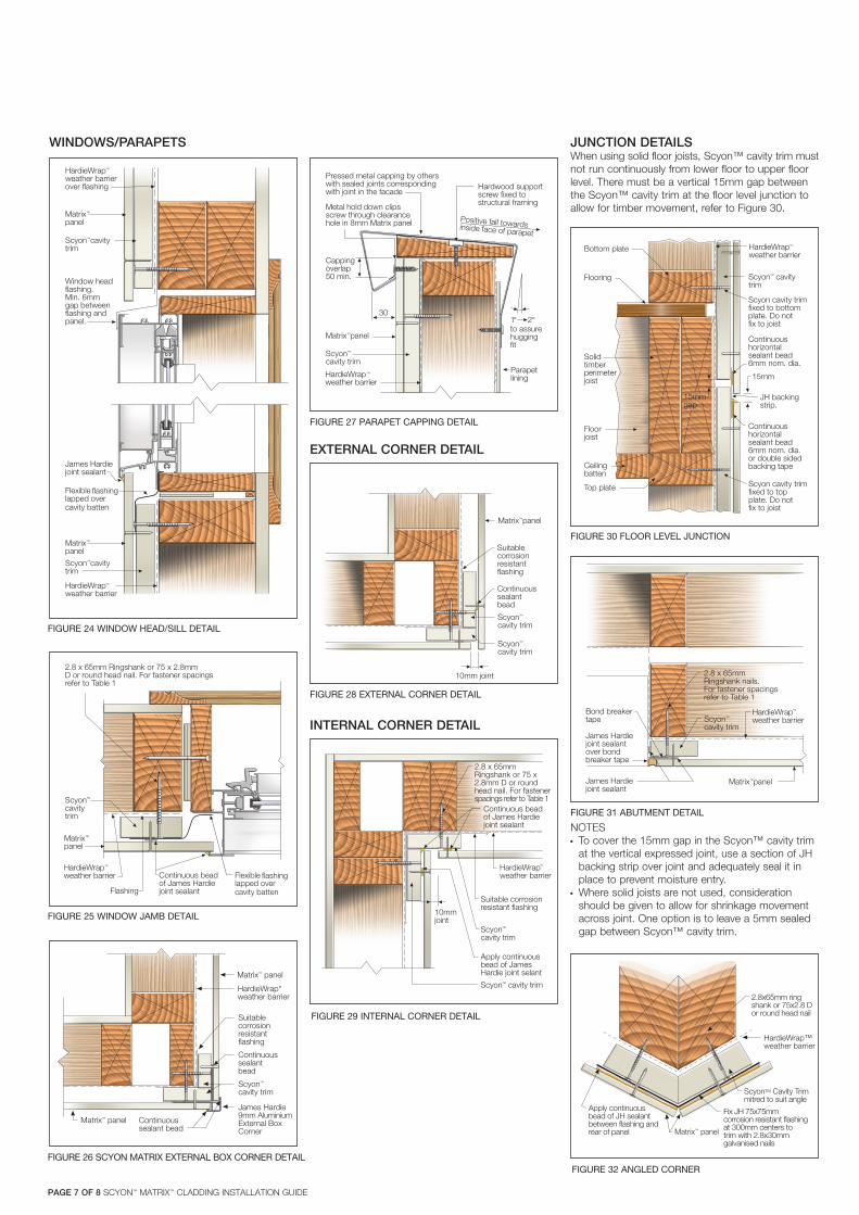
JUNCTION DETAILSWhen using solid floor joists, Scyon™ cavity trim must not run continuously from lower floor to upper floor level. There must be a vertical 15mm gap between the Scyon™ cavity trim at the floor level junction to allow for timber movement, refer to Figure 30.
NOTESn To cover the 15mm gap in the Scyon™ cavity trim
at the vertical expressed joint, use a section of JH backing strip over joint and adequately seal it in place to prevent moisture entry.
n Where solid joists are not used, consideration should be given to allow for shrinkage movement across joint. One option is to leave a 5mm sealed gap between Scyon™ cavity trim.
FIGURE 31 ABUTMENT DETAIL
Metal hold down clipsscrew through clearancehole in 8mm Matrix panel
Scyon™
cavity trim
Matrix™ panel
30
Cappingoverlap50 min.
Pressed metal capping by otherswith sealed joints correspondingwith joint in the facade
Positive fall towardsinside face of parapet
Hardwood supportscrew fixed tostructural framing
Parapetlining
to assurehuggingfit
1º 2º
HardieWrapweather barrier
™
FIGURE 27 PARAPET CAPPING DETAIL
James Hardiejoint sealantover bondbreaker tape
Matrix™ panelJames Hardiejoint sealant
Scyon™
cavity trim
2.8 x 65mmRingshank nails.For fastener spacingsrefer to Table 1
Bond breakertape
HardieWrapweather barrier
™
FIGURE 28 EXTERNAL CORNER DETAIL
Matrix™ panel
Scyon™
cavity trim
Scyon™
cavity trim
Continuoussealantbead
10mm joint
Suitablecorrosionresistantflashing
FIGURE 29 INTERNAL CORNER DETAIL
HardieWrapweather barrier
™
FIGURE 30 FLOOR LEVEL JUNCTION
HardieWrapweather barrier
™
WINDOWS/PARAPETS
FIGURE 24 WINDOW HEAD/SILL DETAIL
Matrix™
panel
Scyon™ cavitytrim
Window headflashing.Min. 6mmgap betweenflashing andpanel.
Matrix™
panel
James Hardiejoint sealant
Scyon™ cavitytrim
Flexiblelapped overcavity batten
HardieWrapweather barrierover flashing
HardieWrapweather barrier
™
™
flashing
FIGURE 25 WINDOW JAMB DETAIL
HardieWrapweather barrier
™
Flexiblelapped overcavity batten
flashing
FIGURE 32 ANGLED CORNER
HardieWrap“weather barrier
FIGURE 26 SCYON MATRIX EXTERNAL BOX CORNER DETAIL
PAGE 7 OF 8 SCYON™ MATRIX™ CLADDING INSTALLATION GUIDE
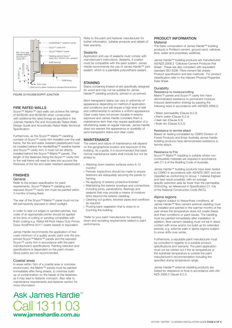
Refer to the paint and fastener manufacturer for further information, suitable products and details of their warranty.
SealantsApplication and use of sealants must comply withmanufacturer’s instructions. Sealants, if coated, must be compatible with the paint system. James Hardie recommends the use of James Hardie™ joint sealant, which is a paintable polyurethane sealant.
STAININGStains containing linseed oil are specifically designed for wood and may not be suitable for James Hardie™ cladding products, primed or un-primed.
Semi-transparent stains can vary in uniformity of appearance depending on method of application and conditions and will require a high level of skill and craftsmanship to achieve a uniform appearance. Clear coats have not proven durable in exterior exposure and James Hardie considers them a maintenance item that may require application of a refurbishing sealer at regular intervals. James Hardie does not warrant the appearance or durability of semi-transparent stains and clear coats.
MAINTENANCEThe extent and nature of maintenance will depend on the geographical location and exposure of the building. As a guide, it is recommended that basic normal maintenance tasks shall include but not be limited to:
n Washing down exterior surfaces every 6-12 months*
n Periodic inspections should be made to ensure fasteners are adequately securing the panels to framing.
n Re-applying of exterior protective finishes*n Maintaining the exterior envelope and connections
including joints, penetrations, flashings and sealants that may provide a means of moisture entry beyond the exterior cladding.
n Cleaning out gutters, blocked pipes and overflows as required.
n Pruning back vegetation that is close to or touching the building.
*Refer to your paint manufacturer for washing down and recoating requirements related to paint performance.
PRODUCT INFORMATIONMaterialThe basic composition of James Hardie™ building products is Portland cement, ground sand, cellulose fibre, water and proprietary additives.
James Hardie™ building products are manufactured AS/NZS 2908.2 ‘Cellulose-Cement Products-Flat Sheet’. These are also compliant with equivalent standard ISO 8336 ‘Fibre-cement flat sheets - Product specification and test methods’. For product classification refer to the relevant Physical Properties Data Sheet.
DurabilityResistance to moisture/rottingMatrix™ panels and Scyon™ cavity trim have demonstrated resistance to permanent moisture induced deterioration (rotting) by passing the following tests in accordance with AS/NZS 2908.2:
n Water permeability (Clause 8.2.2)n Warm water (Clause 8.2.4)n Heat rain (Clause 6.5)n Soak dry (Clause 8.2.5)
Resistance to termite attackBased on testing completed by CSIRO Division of Forest Products and Ensis Australia James Hardie building products have demonstrated resistance to termite attack.
Resistance to FireScyon™ Matrix™ cladding is suitable where non-combustible materials are required in accordance with C1.9 of the Building Code of Australia.
James Hardie™ building products have been tested by CSIRO in accordance with AS/NZS 3837 and are classified as conforming to Group 1 material (highest and best result possible), with an averagespecific extinction area far lower than the permissible 250m2/kg, as referenced in Specification C1.10a of the National Construction Code (NCC).
Alpine regionsIn regions subject to freeze/thaw conditions, all James Hardie™ fibre cement external cladding must be installed and painted in the warmer months of the year where the temperature does not create freeze and thaw conditions or paint issues. The cladding must be painted immediately after installation. In addition, fibre cement cladding must not be in direct contact with snow and/or ice build up for extended periods, e.g. external walls in alpine regions subject to snow drifts over winter.
Furthermore, a reputable paint manufacturer must be consulted in regards to a suitable product, specifications and warranty. The paint application must not be carried out if the air temperature or the substrate temperature is outside the paint manufacturer’s recommendation including the specified drying temperature range.
James Hardie™ external cladding products are tested for resistance to frost in accordance with AS/NZS 2908.2 Clause 8.2.3.
FIRE RATED WALLSScyon™ Matrix™ clad walls can achieve fire ratings of 60/60/60 and 90/90/90 when constructed with additional fire rated linings as specified in the JJames Hardie’s Fire and Acoustically Rated Walls Design Guide and Acoustically Rated Walls Technical Specification.
Furthermore, as the Scyon™ Matrix™ cladding consists of Scyon™ cavity trim installed over the wall frame, the fire and water resistant plasterboard must be installed behind the HardieWrap™ weather barrier and Scyon™ cavity trim. It must not be directly installed behind the Scyon™ Matrix™ panels. The length of the fasteners fixing the Scyon™ cavity trim to the wall frame will need to take into account the thickness of the fire and water resistant plasterboard.
FINISHESGeneralRefer to the project specification for paint requirements. Scyon™ Matrix™ cladding and exposed Scyon™ cavity trim must be painted within 3 months of being fixed.
The rear of the Scyon™ Matrix™ panel must not be left permanently exposed to direct sunlight.
In order to seal cut edges or sanded patches, two coats of an appropriate primer should be applied at the time of cutting or sanding compatible with finish coating e.g. Wattyl Kill Rust Heavy Duty Primer, Dulux AcraPrime 501/1 (water based) or equivalent.
James Hardie recommends the application of two coats minimum of a quality acrylic paint over the pre-primed Scyon™ Matrix™ panels and the exposed Scyon™ cavity trim in accordance with the paint manufacturer’s specifications. Painting selection and specifications is dependant on the paint chosen. Gloss paints are not recommended.
Coastal areasIn areas within 1km of a coastal area or corrosive environment, the Matrix™ panels must be painted immediately after fixing sheets, to minimise build up of contamination on the heads of the fasteners, as it may lead to fastener corrosion. Also refer to maintenance requirements and fastener section for more information.
HardieWrap™ weather barrier
FIGURE 33 FACADE/SOFFIT JUNCTION
SCYON™ MATRIX™ CLADDING INSTALLATION GUIDE PAGE 8 OF 8

Notes

Notes


For information and advice call 13 11 03 | jameshardie.com.au
© 2019 James Hardie Australia Pty Ltd ABN 12 084 635 558 ™ and ® denote a trademark or registered mark owned by James Hardie Technology Limited.
Australia May 2019