ez1 to 888 tutorial
TRANSCRIPT

© Trossen Robotics
Tutorial:Using the MaxSonar-EZ1 and LV-MaxSonar-EZ1 with the Phidgets 8/8/8
Interface Kit
The MaxSonar-EZ1 is a very compact and versatile ultrasonic distance sensor. It outputs range information in
three forms: TTL serial, PWM, and 0V-2.5V analog. This tutorial will concentrate on using the Phidgets 8/8/8Interface Kit to read the analog output of one EZ1 sensor and multiple EZ1 sensors.
Connecting One Sensor
Basic connections between EZ1 and analog connector
When using only one EZ1 sensor, you can connect the three wires of a Phidgets analog sensor cable directly tothe ground, power, and analog terminals on the sensor. See the above graphic for details.
We went a step further by mounting the sensor and a female connector on a piece of prototype board, which inturn was bolted to a sensor bracket.
Our prototype sensor assembly
When the sensor’s serial lines are not in use, the sensor goes into a continuous run mode in which it senses the
range every 49 ms and outputs a continuous analog signal representing the distance on a scale of 10 mV per inch. This works great if you’re only using one sensor.
© Trossen Robotics
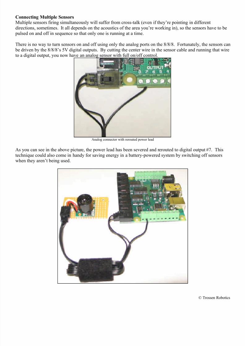
Connecting Multiple SensorsMultiple sensors firing simultaneously will suffer from cross-talk (even if they’re pointing in different
directions, sometimes. It all depends on the acoustics of the area you’re working in), so the sensors have to be pulsed on and off in sequence so that only one is running at a time.
There is no way to turn sensors on and off using only the analog ports on the 8/8/8. Fortunately, the sensors can
be driven by the 8/8/8’s 5V digital outputs. By cutting the center wire in the sensor cable and running that wireto a digital output, you now have an analog sensor with full on/off control.
Analog connector with rerouted power lead
As you can see in the above picture, the power lead has been severed and rerouted to digital output #7. This
technique could also come in handy for saving energy in a battery-powered system by switching off sensorswhen they aren’t being used.
© Trossen Robotics
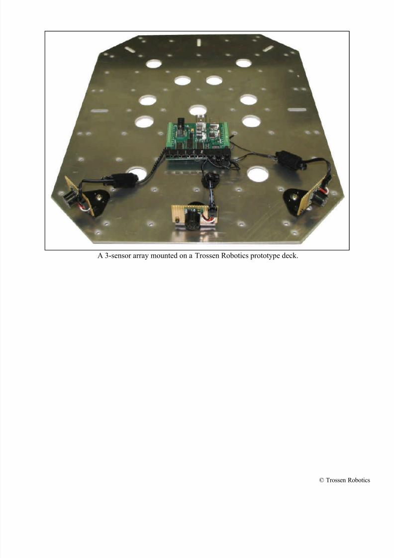
A 3-sensor array mounted on a Trossen Robotics prototype deck.

© Trossen Robotics
The switching action, though not automated in thisexample, can be demonstrated using the Phidget
Interface Kit example software (interfacekit-controller.exe). Sensors are connected to analog
inputs 5, 6, and 7; and they are driven by digitaloutputs 5, 6, and 7.
Knowing that the sensors are pointed straight forward
and 45 degrees to the left and right, you can get arough idea of the robot’s surroundings. There is an
object about a foot away from the front right sensor,and enough room to the front and front left to
maneuver around it.
Up to eight sensors can be connected to an 8/8/8, andthe interface boards can be daisy-chained using the
USB hubs built into each board.

© Trossen Robotics
Parts List
8/8/8 Interface Kithttp://www.trossenrobotics.com/store/p/3202-InterfaceKit-8-8-8.aspx
LV-MaxSonar-EZ1
http://www.trossenrobotics.com/store/p/4871-LV-MaxSonar-EZ1.aspx
Medium Perf Board
http://www.trossenrobotics.com/store/p/3518-Medium-Solderable-Perf-Board.aspx
Board Mounting Analog Jack http://www.trossenrobotics.com/store/p/3464-Board-Mounting-Analog-Jack.aspx
24” Sensor Cable
http://www.trossenrobotics.com/store/p/3260-24-Inch-Sensor-Cable.aspx
Sensor Bracket
http://www.trossenrobotics.com/store/p/3263-Servo-IR-Sensor-Bracket.aspx