ezuhf r/c control system ezuhf r/c control system is a ... operation options for 431-433mhz,...
TRANSCRIPT
ImmersionRC | EzUHF R/C Control System 1
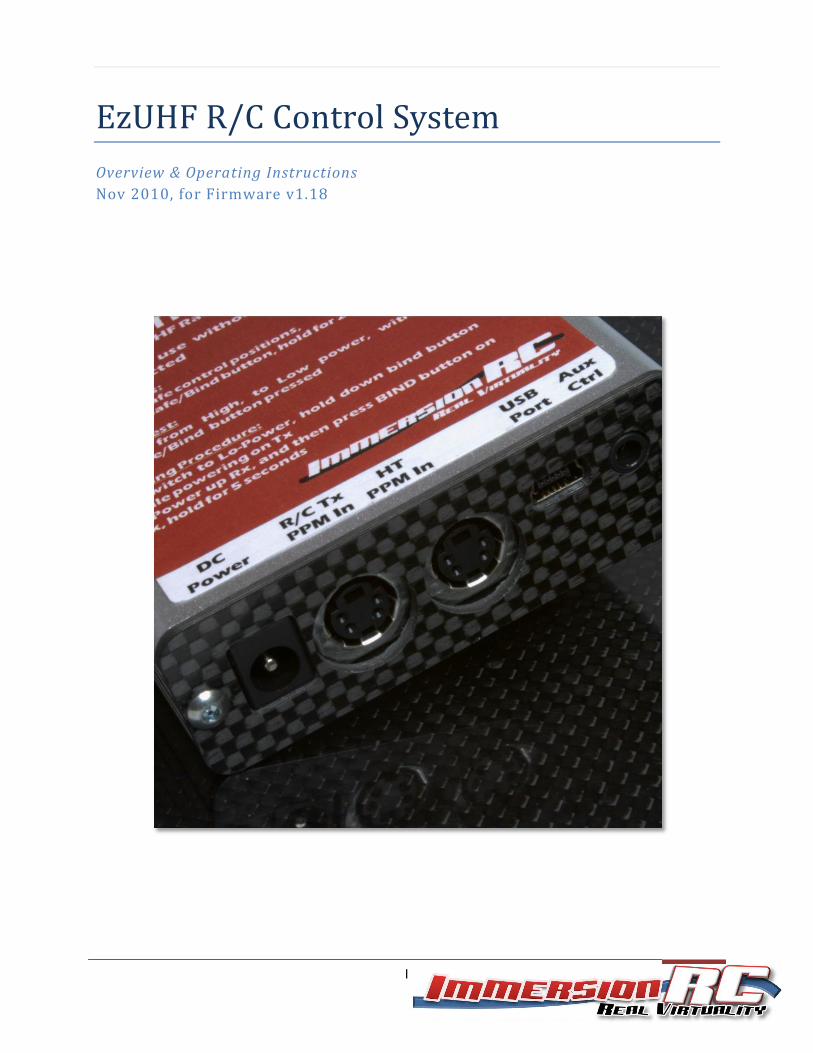
EzUHF R/C Control System
Overview & Operating Instructions
Nov 2010, for Firmware v1.18

ImmersionRC | EzUHF R/C Control System 2
Table of Contents
Overview ....................................................................................................................................................... 3
Features/Specifications ............................................................................................................................. 3
Security ..................................................................................................................................................... 4
Radio Licensing .......................................................................................................................................... 4
EzUHF Transmitter ........................................................................................................................................ 4
Powering the transmitter.......................................................................................................................... 4
Binding ...................................................................................................................................................... 5
Failsafe ...................................................................................................................................................... 6
Power Level control .................................................................................................................................. 6
Range Testing ............................................................................................................................................ 6
Transmitter Compatibility ......................................................................................................................... 7
S-Video pin-out: .................................................................................................................................... 7
PPM Input & Head-Tracker input pin-out: ............................................................................................ 7
Futaba (square) to EzUHF cable: ............................................................................................................... 8
Multiplex (DIN) to EzUHF (Mini-DIN) cable: .............................................................................................. 9
Cabling the TrackR2 to the EzUHF Transmitter: ..................................................................................... 10
EzUHF Receivers .......................................................................................................................................... 11
EzUHF Receiver, 8 channel version, Connections ................................................................................... 12
Powering the Rx when using high-powered servos ............................................................................ 12
Receiver antenna configuration .............................................................................................................. 13
Driver/Software Installation on a PC .......................................................................................................... 13
EzUHF -> EzOSD link ................................................................................................................................ 13
Antenna Selection ....................................................................................................................................... 15
Diamond SRH771 .................................................................................................................................... 15
Active Robots 433MHz Straight .............................................................................................................. 16
Active Robots 433MHz R/A ..................................................................................................................... 16
Antenna extension cables ....................................................................................................................... 16
IMPORTANT: Known Sources of Interference ........................................................................................ 18
Appendix A: Binding multiple transmitters to a single receiver ................................................................. 19
Appendix B: Diagnostics .............................................................................................................................. 20

ImmersionRC | EzUHF R/C Control System 3
Overview
The EzUHF R/C control system is a reliable R/C control uplink for FPV and UAV pilots who desire a robust
control system for safe control at longer distances.
It was designed with the FPV/UAV pilot in mind, the only such system with a dedicated head-tracker
port, ensuring compatibility with a wide range of radios.
An ‘Aux Ctrl’ port is available to connect to a ‘control board’, for in-flight UAV configuration without
sacrificing valuable control channels.
Features/Specifications
Reliable FHSS Link (Frequency Hopping, Spread Spectrum)
433MHz/70cm Ham band operation
Options for 431-433MHz, 433-435MHz, 435-437MHz.
Spectrally clean GFSK modulation
600mW (~28dBm) output power, with 200mW low-power mode
Direct head-tracker input, adding head-tracker compatibility to most radios
Power switch, boost power when at long range (optionally drive from unused control on the R/C Tx)
Standard SMA antenna connector, compatibility with 433MHz/70cm Ham-band antennas
Flexible buffered, AC-coupled, PPM input, ensures compatibility with 3.3v thru 9.6v PPM levels
Standard USB port (Mini-A) for firmware upgrades, and system configuration
Single pushbutton learning of failsafe positions
Binding function, which allows binding Single Tx->Rx, Multi Tx->Rx, and Single Tx->Multi Rx
Mates with 8 channel, and 4 channel EzUHF receivers
Spectrum analyzer built into EzUHF receivers, to aid in debugging RF interference
Power sourced directly from the R/C Tx (Futaba), or optional DC power jack
Built in receiver, for future expansion
Custom extruded brushed aluminum enclosure
Dimensions 85 x 74 x 23mm 118g
Power Requirements: 9-12v DC 250 mA @ 12v, in 600mW mode, 85mA @ 12v, in 200mW mode

ImmersionRC | EzUHF R/C Control System 4
Security
The ImmersionRC team does not promote reckless long-range flight, where property and/or lives are put
at risk.
This R/C control system was brought to the market for use by responsible end-users, who are aware of,
and comply with, local legislation regarding FPV/UAV flight.
ImmersionRC accepts no responsibility for property damage, parts damage, model damage, or personal
injury due to the misuse of the EzUHF, or any other ImmersionRC product.
Radio Licensing
The EzUHF R/C control system transmits on radio frequencies which may require a license for use.
The specific band of frequencies is firmware-dependent, and in some cases may be tailored to meet a
retailer/distributor’s requirements.
The default band used is 433-435MHz, which falls in the 70cm Amateur Radio band.
Because of this, this product requires an Amateur radio (or similar) license to use in most parts of the
world.
Please check your local legislation before using this product!
EzUHF Transmitter
Powering the transmitter The EzUHF transmitter has two flexible power options. Both of which may be used for additional
redundancy:
1) Power supplied via the 4-pin mini-din connector.
In the case where the transmitter is connected to a futaba radio, with 9.6v, or 3s Lipo power
source, this is the preferred method of powering the transmitter.
2) Power supplied via the DC power jack.
In cases where the R/C transmitter either doesn’t provide power via its trainer connector, or
when a lower voltage is available (2s radios for example), it is preferred to power the EzUHF via
the DC power jack.
The power jack is center-pin positive, 2mm internal pin, 5.5mm outer diameter.
A suitable plug is Mouser #502-S760BK
NOTE: The EzUHF transmitter may safely be powered via both connectors simultaneously, even if two
different voltages are presented.
ImmersionRC | EzUHF R/C Control System 5
As an example: Take the case of a R/C transmitter which uses a 2s LiPo pack. The EzUHF will emit slightly
less power than specified (approx. 25dBm on 8v, vs. around 29dBm on 11.1v) when powered this way.
In most cases this power difference is insignificant, for buzzing around the local flying field, this is a very
reasonable power level.
If full power is desired in this case, a 3s LiPo pack (or equivalent) can safely be connected to the DC
Power jack, providing both higher power, and redundancy (no power will be consumed from the R/C
transmitter’s battery until the external pack is either drained, or removed).
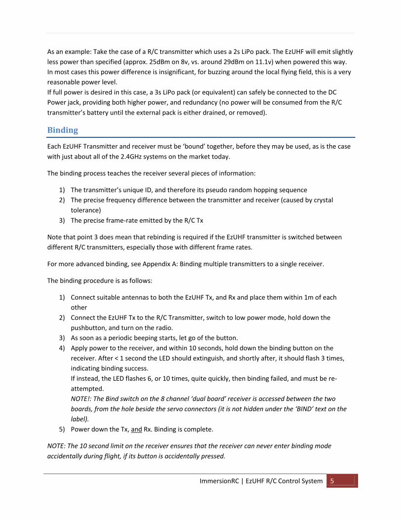
Binding
Each EzUHF Transmitter and receiver must be ‘bound’ together, before they may be used, as is the case
with just about all of the 2.4GHz systems on the market today.
The binding process teaches the receiver several pieces of information:
1) The transmitter’s unique ID, and therefore its pseudo random hopping sequence
2) The precise frequency difference between the transmitter and receiver (caused by crystal
tolerance)
3) The precise frame-rate emitted by the R/C Tx
Note that point 3 does mean that rebinding is required if the EzUHF transmitter is switched between
different R/C transmitters, especially those with different frame rates.
For more advanced binding, see Appendix A: Binding multiple transmitters to a single receiver.
The binding procedure is as follows:
1) Connect suitable antennas to both the EzUHF Tx, and Rx and place them within 1m of each
other
2) Connect the EzUHF Tx to the R/C Transmitter, switch to low power mode, hold down the
pushbutton, and turn on the radio.
3) As soon as a periodic beeping starts, let go of the button.
4) Apply power to the receiver, and within 10 seconds, hold down the binding button on the
receiver. After < 1 second the LED should extinguish, and shortly after, it should flash 3 times,
indicating binding success.
If instead, the LED flashes 6, or 10 times, quite quickly, then binding failed, and must be re-
attempted.
NOTE!: The Bind switch on the 8 channel ‘dual board’ receiver is accessed between the two
boards, from the hole beside the servo connectors (it is not hidden under the ‘BIND’ text on the
label).
5) Power down the Tx, and Rx. Binding is complete.
NOTE: The 10 second limit on the receiver ensures that the receiver can never enter binding mode
accidentally during flight, if its button is accidentally pressed.

ImmersionRC | EzUHF R/C Control System 6
See the advanced section, on how to bind multiple transmitters to a single receiver.
Failsafe
If, for any reason, the UHF link is broken, the receiver will wait for approximately 1 second for the link to
be restored, and then will enter failsafe mode.
The failsafe servo positions are programmed using the button on the transmitter.
To set this up, two phases are recommended.
1) With the plane on the ground, and servo positions neutral, throttle cut, hold down the
transmitter’s bind/failsafe button until the transmitter beeps. This will set a reasonable default
failsafe ready for the first flight
2) With the plane in flight, set the controls in a suitable position for the failsafe, and re-program
the failsafe. In most cases, ‘suitable position’ means throttle cut, and a gentle turn radius, to let
the plane circle gently until it lands, but of course every application is a little different.
Power Level control
The toggle-switch on the top of the EzUHF Tx is used to switch between high and low power modes.
Even if full feedback of uplink status is available on the EzOSD display, it is highly recommended to fly in
low-power mode most of the time, switching to high-power mode if required.
The difference in power levels between the two modes is approximately 6dB, which corresponds to a
factor of 2 in range, ensuring plenty of margin.
Range Testing
Before any flight it is highly recommended to perform a range test on the ground. For this, use at
minimum the low-power mode, or more ideally, attenuate the transmitter output using an SMA
attenuator for the range test (NOTE: Do not forget to remove the attenuators before the flight!!!!).
A 20dB SMA attenuator, easily sourced on Ebay, is a good choice for this.
The transmitter does include a range-test feature, which drops power to approx. 13dBm (20mW).
To access this mode, switch from High to Low power mode with the bind pushbutton pressed.
WARNING: Do not forget to cycle Tx power before flying to leave range-testing mode.
ImmersionRC | EzUHF R/C Control System 7
Transmitter Compatibility
The PPM input circuit of the EzUHF Tx is designed to support a large range of transmitters, with PPM
input voltages ranging from 3.3v, all the way to 9.6v or more.
Most of the in-flight testing was performed using Futaba systems, which is used by the system's
designers. This is therefore the preferred radio for use with the EzUHF link.
Support for other radios will be added as further testing is done.
The EzUHF uses standard 4-pin Mini-DIN connectors, for the R/C transmitter link (PPM-In), and the link
to the Headtracker (see below: Cabling the TrackR2 to the EzUHF Transmitter).
These connectors are the same as those used on the TrackR2 headtracker, with the same pinout.
These connectors are also the same as those used by the popular S-Video standard, which makes finding
pre-molded connectors and cables quite easy. The S-Video cables have Chroma/Gnd, and Y-Luma/Gnd
as two twisted pairs, these correspond to Pwr/Gnd, and PPM In/N/C, which won't cause any problems.
Note that the S-Video extension cables (Male -> Female) may be used as extension cables, but cannot
be used to connect the TrackR2 to the EzUHF Transmitter (see below)
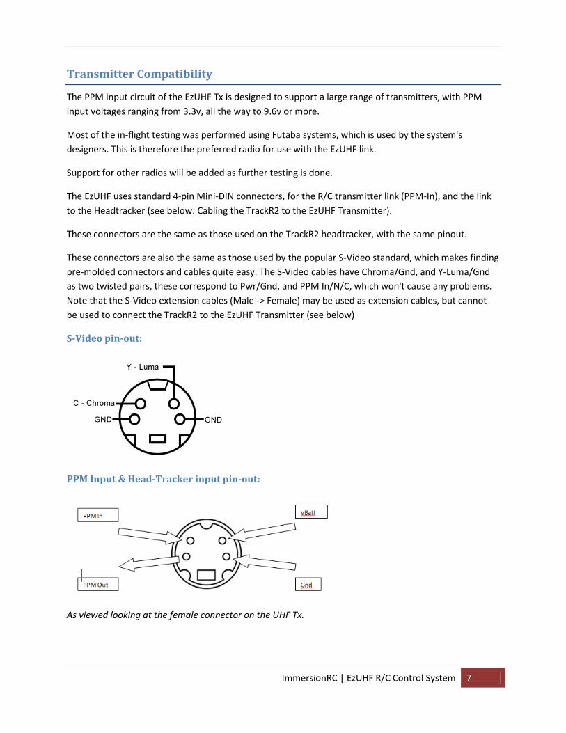
S-Video pin-out:
PPM Input & Head-Tracker input pin-out:
As viewed looking at the female connector on the UHF Tx.

ImmersionRC | EzUHF R/C Control System 8
To remove any confusion, the pin-out is marked directly on a photo of the transmitter below:
Futaba (square) to EzUHF cable:
A Futaba to EzUHF cable is supplied with the EzUHF. The wiring diagram of this cable is shown below for
reference.
Not Used
Gnd
VBatt
PPM In
ImmersionRC | EzUHF R/C Control System 9
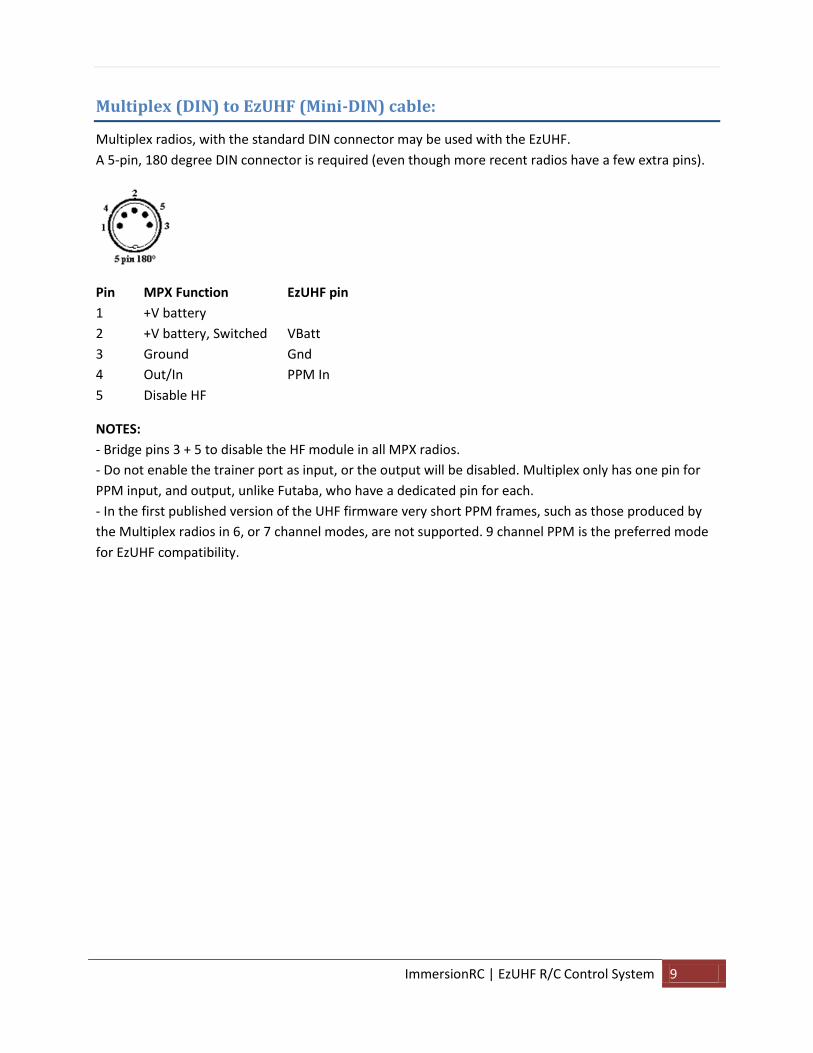
Multiplex (DIN) to EzUHF (Mini-DIN) cable:
Multiplex radios, with the standard DIN connector may be used with the EzUHF.
A 5-pin, 180 degree DIN connector is required (even though more recent radios have a few extra pins).
Pin MPX Function EzUHF pin
1 +V battery
2 +V battery, Switched VBatt
3 Ground Gnd
4 Out/In PPM In
5 Disable HF
NOTES:
- Bridge pins 3 + 5 to disable the HF module in all MPX radios.
- Do not enable the trainer port as input, or the output will be disabled. Multiplex only has one pin for
PPM input, and output, unlike Futaba, who have a dedicated pin for each.
- In the first published version of the UHF firmware very short PPM frames, such as those produced by
the Multiplex radios in 6, or 7 channel modes, are not supported. 9 channel PPM is the preferred mode
for EzUHF compatibility.

ImmersionRC | EzUHF R/C Control System 10
Cabling the TrackR2 to the EzUHF Transmitter:
To cable the TrackR2 to the EzUHF transmitter a 4-pin Mini-DIN to 4-pin Mini-DIN cable is required.
This cable will be available late November 2010 from ImmersionRC resellers. A standard S-Video cable
cannot be used due to the necessity to cross over the PPM In/out connections.
Note that both connectors are viewed from the back of the male connector, where the solder
connections are to be made.
Note that the switch on the TrackR2 must be in the ‘Normal’ position, and not ‘Low-End’ when
connecting it to the EzUHF.
ImmersionRC | EzUHF R/C Control System 11
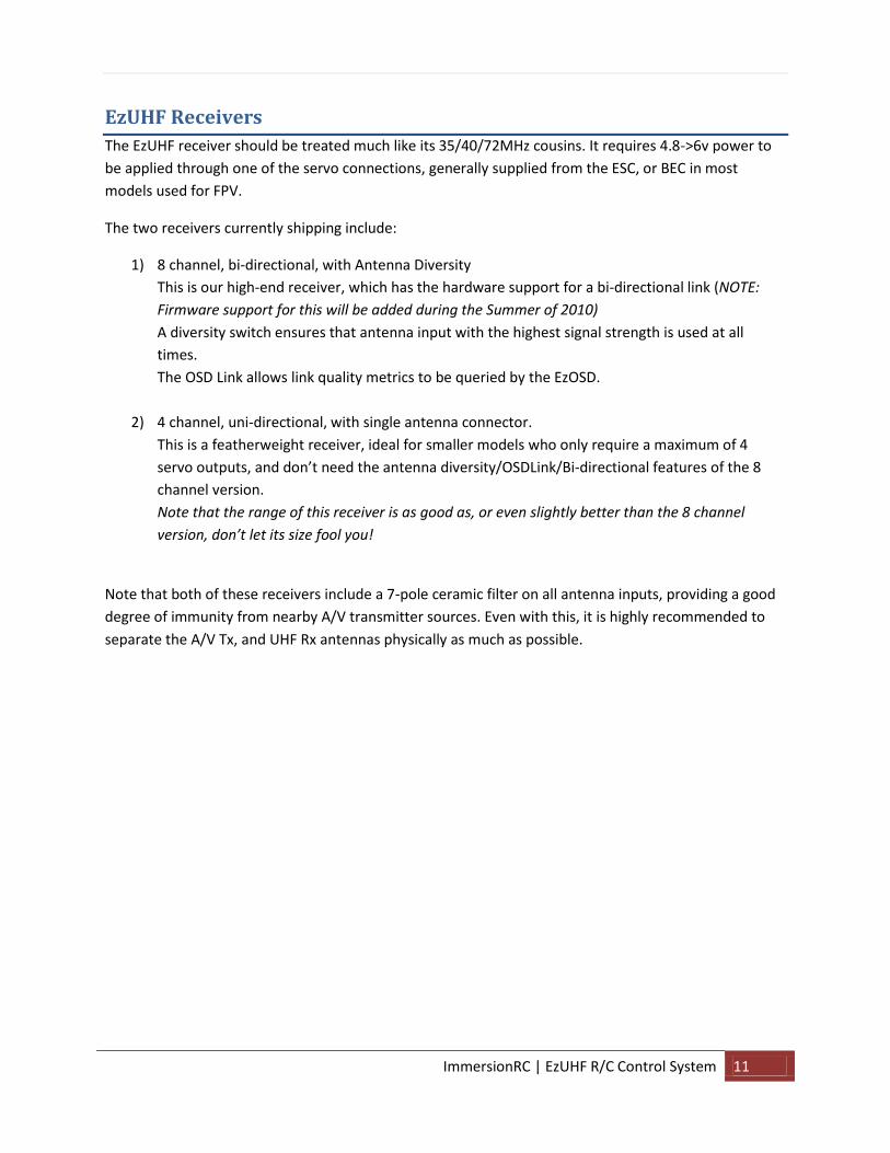
EzUHF Receivers
The EzUHF receiver should be treated much like its 35/40/72MHz cousins. It requires 4.8->6v power to
be applied through one of the servo connections, generally supplied from the ESC, or BEC in most
models used for FPV.
The two receivers currently shipping include:
1) 8 channel, bi-directional, with Antenna Diversity
This is our high-end receiver, which has the hardware support for a bi-directional link (NOTE:
Firmware support for this will be added during the Summer of 2010)
A diversity switch ensures that antenna input with the highest signal strength is used at all
times.
The OSD Link allows link quality metrics to be queried by the EzOSD.
2) 4 channel, uni-directional, with single antenna connector.
This is a featherweight receiver, ideal for smaller models who only require a maximum of 4
servo outputs, and don’t need the antenna diversity/OSDLink/Bi-directional features of the 8
channel version.
Note that the range of this receiver is as good as, or even slightly better than the 8 channel
version, don’t let its size fool you!
Note that both of these receivers include a 7-pole ceramic filter on all antenna inputs, providing a good
degree of immunity from nearby A/V transmitter sources. Even with this, it is highly recommended to
separate the A/V Tx, and UHF Rx antennas physically as much as possible.

ImmersionRC | EzUHF R/C Control System 12
EzUHF Receiver, 8 channel version, Connections
Servo connectors on the 8 channel receiver have the pin-out shown below.
Note that the binding button is not hidden under the padded label, it is located between the
two stacked PCBs, and needs to be pressed using a non-conductive stylus, or similar.
Powering the Rx when using high-powered servos
It is very important to take care with powering the Rx, especially when high torque digital servos are
used.
If a BEC is used, ensure that it can deliver the current required by the servos. Digital servos can create
huge current pulses on the power line, and if the impedance of the supply is too high, these will cause
the receiver to malfunction.
The use of a high-performance BEC, such as the Turnigy 5-7.5A UBEC (HobbyKing) is recommended
instead of the BEC built into the ESC.
Alternatively, for installations on larger planes, with many servos, a PowerBox should be considered.
Gnd
+5/6v
Signal

ImmersionRC | EzUHF R/C Control System 13
Receiver antenna configuration
The 8 channel diversity receiver has, as its name might suggest, two antenna inputs.
The receiver does expect antennas to be connected to both of these antenna connectors, unless
configured otherwise. It is not advisable to leave the receiver configured in diversity mode, and connect
just one antenna.
The ImmersionRCTools application, available from the ImmersionRC website, can be used to configure
the receiver antenna configuration for cases where only a single antenna is used.
Driver/Software Installation on a PC
The Windows software to support the EzUHF may be downloaded from the EzUHF website here:
http://www.immersionrc.com/EzUHF.htm
EzUHF -> EzOSD link
Linking the EzUHF receiver to the EzOSD can create a very powerful combination.
The EzUHF receiver (8 channel version) will periodically inform the EzOSD of the following
measurements:
1. The RSSI (received signal strength) on each of the two antennas
2. The overall signal quality (which includes packet loss information)
3. Frequency error measurement (difference between Tx and Rx frequencies)
4. Error rates per frequency bin
These measurements are in turn downlinked via the telemetry stream, and may be shown on the
antenna tracker LCD display, displayed in the ImmersionPlayer, or shown live using the iPad/iPhone
iTelemetryFPV application.
The on-screen data provides direct feedback to the pilot of any problems with the uplink in real time.
The recorded telemetry stream may be used to diagnose problems after a flight, and can be a powerful
tool for comparing antenna performance, antenna position, etc.
The connector used for this link is the Molex connector named ‘OSD Link’, shown below:

ImmersionRC | EzUHF R/C Control System 14
For DIY cables, the following Farnell parts may be used:
5-POS Molex ‘PicoBlade’ Housing 615109
Flying lead, 300mm 1125274
The EzUHF Rx end of the cable uses a 5-pin Molex connector, as used for the GPS connection to the
EzOSD PCB (the OSD end, not the GPS end).
ImmersionRC | EzUHF R/C Control System 15
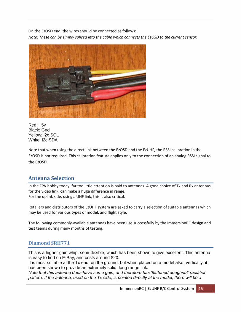
On the EzOSD end, the wires should be connected as follows:
Note: These can be simply spliced into the cable which connects the EzOSD to the current sensor.
Red: +5v Black: Gnd Yellow: i2c SCL White: i2c SDA
Note that when using the direct link between the EzOSD and the EzUHF, the RSSI calibration in the
EzOSD is not required. This calibration feature applies only to the connection of an analog RSSI signal to
the EzOSD.
Antenna Selection
In the FPV hobby today, far too little attention is paid to antennas. A good choice of Tx and Rx antennas, for the video link, can make a huge difference in range. For the uplink side, using a UHF link, this is also critical. Retailers and distributors of the EzUHF system are asked to carry a selection of suitable antennas which may be used for various types of model, and flight style. The following commonly-available antennas have been use successfully by the ImmersionRC design and test teams during many months of testing.
Diamond SRH771
This is a higher-gain whip, semi-flexible, which has been shown to give excellent. This antenna is easy to find on E-Bay, and costs around $20. It is most suitable at the Tx end, on the ground, but when placed on a model also, vertically, it has been shown to provide an extremely solid, long range link. Note that this antenna does have some gain, and therefore has ‘flattened doughnut’ radiation pattern. If the antenna, used on the Tx side, is pointed directly at the model, there will be a

ImmersionRC | EzUHF R/C Control System 16
significant amount of attenuation (something that should be very familiar to users of standard R/C radios). Turn 90 degrees to the model to avoid this.
The antenna manufacturer Nagoya also sells a version of this (possibly made in the same factory), called the NA-771. This is generally a bit cheaper, and appears to perform as well.
Active Robots 433MHz Straight
http://www.active-robots.co.uk/433mhz-antenna-straight-p-544.html Model #: ANT-433MS This antenna works well when antennas are placed remotely from the receiver using extension cables (see below), terminated in bulkhead SMA connectors. These connectors can be embedded in a wing, or fuselage, pointing straight up (or down).
Active Robots 433MHz R/A
http://www.active-robots.co.uk/433mhz-antenna-rightangled-p-545.html Model #: ANT-433MR Two of these antennas, angled at approx. 45 degrees from each other, connected directly to the two 8 channel Rx antenna inputs, work very nicely, and protect against huge losses due to cross-polarization.
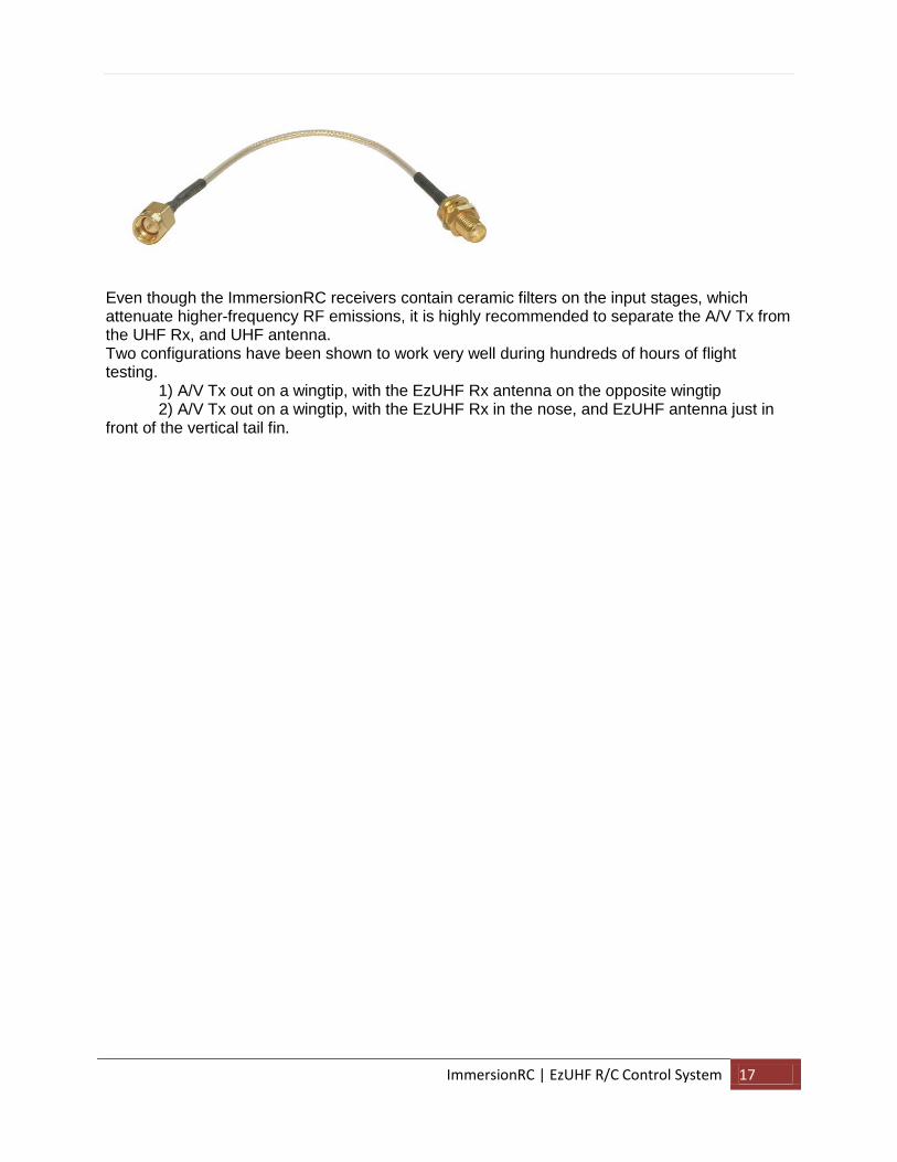
Antenna extension cables
Since the EzUHF uses standard SMA connectors for all antenna connections, it is very easy to find, or construct, extension cables.
ImmersionRC | EzUHF R/C Control System 17
Even though the ImmersionRC receivers contain ceramic filters on the input stages, which attenuate higher-frequency RF emissions, it is highly recommended to separate the A/V Tx from the UHF Rx, and UHF antenna. Two configurations have been shown to work very well during hundreds of hours of flight testing. 1) A/V Tx out on a wingtip, with the EzUHF Rx antenna on the opposite wingtip 2) A/V Tx out on a wingtip, with the EzUHF Rx in the nose, and EzUHF antenna just in front of the vertical tail fin.

ImmersionRC | EzUHF R/C Control System 18
IMPORTANT: Known Sources of Interference
There are several cameras which have been shown to emit broadband noise which can greatly
limit the range of any UHF R/C system (FHSS or not). The use of these cameras should be
avoided on any plane controlled by a UHF link.
This list will be extended as more cameras are tested.
KT&C ‘VSN505’ a.k.a KX550 Emits broadband noise in the ~310MHz to ~610MHz band
Ground test range reduced to 30% of range without it.
Up to date information on other cameras can also be found by googling the name of the camera
along with the keyword ‘UHF’.
Note that the popular GoPro cameras do have a relatively powerful noise emission at around
432MHz. These don’t seem to affect the EzUHF much in practice, but it is a good idea to
separate the GoPro from the UHF Rx/Antenna as much as possible.
As a rule of thumb, if the RSSIs for an EzUHF system look good (-60, -80dBm range), and the
link quality indicator is often dipping below 100%, suspect an interfering source on the plane.
Cameras (SD and HD), and poorly designed switching power supplies (especially 5v->12v step-
ups) should be the first thing to look at.
To assist in debugging RF interference problems, the ImmersionRC tools, v1.12 or greater,
along with a version of the EzUHF Rx firmware v1.14 or greater, can replace a spectrum
analyzer worth thousands of dollars. The plot below shows a GoPro HD camera radiating
around 432MHz (the EzUHF, in its standard configuration, occupies the 433 -> 435MHz band,
so the GoPro in this case doesn’t affect range much).

ImmersionRC | EzUHF R/C Control System 19
Appendix A: Binding multiple transmitters to a single receiver
This mode is useful in a couple of scenarios:
1) When redundancy is required, for safety reasons. One transmitter may be switched off, and
another on, to recover the model.
2) To increase security during long range flights, or when a plane, once leaving line-of-sight for a
first pilot, is passed to a second.
This appendix will be completed once the feature is fully supported in the firmware.

ImmersionRC | EzUHF R/C Control System 20
Appendix B: Diagnostics
Problem: Rx LED doesn’t light
Check BEC voltage and polarity. Power the Rx via USB temporarily, if this causes the LED to light, and
‘beat’ when the Tx is powered on, then the BEC/Rx pack should be tested.
Problem: No response from the Transmitter
The transmitter should beep three times when the R/C transmitter is powered on.
If it doesn’t, try powering the transmitter via USB, if the beeps are heard when powering this way, the
cable between the R/C Tx, and the EzUHF Tx, should be investigated.
Problem: Tx and Rx are correctly powered, but servos don’t move.
1. Ensure that the R/C transmitter is not in PCM mode, this is a common mistake. The transmitter
must be in PPM mode in order for the EzUHF Tx to successfully decode the servo positions.
2. Ensure that the UHF Tx and Rx have been correctly bound together. See the section ‘Binding’
earlier in this document.
Problem: Tx beeps continuously, even when not in Bind mode
Beep codes can identify the source of the problem. Combinations of long, and short beeps will be
emitted, and can be identified using the following table.
_ . Transmitter internal error, return for service (Xtal)
_ . . Transmitter internal error, return for service (TxOvfl)
_ . . . Detected PCM as opposed to PPM, change R/C Tx Mode to PPM
_ . . . . PPM not detected at power-up (Tx connected to HT input?)
. . . PPM Timeout, connection problem between R/C Tx and EzUHF
Common problems are _ . . . which indicates that the R/C Tx is in PCM mode, instead of PPM. The
EzUHF (and all other equivalent systems) require PPM as input, and not PCM.
Anoter common problem is _ . . . . which indicates that a PPM signal was not sensed, generally
indicating that the R/C Tx is connected to the wrong connector.

ImmersionRC | EzUHF R/C Control System 21
Problem: RSSI values are good, but the link quality indicator is often below 100%.
This is (in almost all cases) an interfering RF source located on the plane. Look for cameras which radiate
unintentionally in the UHF band, or noisy switching regulators, especially those used to switch up from
5v to 12v to run a 12v camera.