f-18e super hornet navigation systems plugin for the pc ... · f-18e super hornet navigation...
TRANSCRIPT

F-18E Super Hornet Navigation Systems Plugin
for the PC for X-Plane 9
Overview:
This add-on for X-Plane is used by the U.S. Navy for hypoxia training. It provides nearlycomplete navigational functionality to the pilot such that they can fly a route as they areaccustomed while hypoxia training is conducted. The simulation needs to be as accurate aspossible so that they are not distracted by inaccuracies during training.
Besides providing navigational functionality, many extras have been added to make this a moreinteresting add-on. This is just a start. More complete functionality will be offered in a futurerelease for the F-18C and CF-18 Hornet. Below is a list of features included in this plugin:
Fly-by-wire (FBW) Control
• Automatic pitch stability
• Automatic flap scheduling
• G-limiting and G-limiting override
Custom Multi-Mode Heads Up Display (HUD)
• Navigation mode
• Landing mode
• Course Line Steering mode
• Ground attack with CCIP and Automatic bombing modes
• De-clutter function
• Brightness control
• Designed to work in the virtual cockpit
Navigation/Weapon Multi-Function Displays (MFDs)
• Supports loading of multiple routes (standard x-plane fms files)
• TACAN navigation using included world-wide TACAN navigation database
• Selecting heading modes
• Waypoint selection and auto waypoint sequencing
• Target designation of waypoint for automatic bomb delivery
• Course Line Steering to TACANs or waypoints
• 2D pop-up for easy reading
Up-Front Control Display (UFCD)
• Allows setting of COMM, ILS, ADF, and TACAN channels
• Includes autopilot functionality for altitude hold (baro and radar) and heading hold
• Has a special joystick configuration menu for joystick setup with X-Plane

Engine Fuel Display (EFD)
• Fuel level display for all tanks
• Bingo fuel setting with audible bingo warning tone
• Nozzle display
Extras
• Accurate virtual cockpit
• Animation of engine nozzles
• Head view is moved laterally as you look back so you can see the tails instead of theheadrest
INSTALLATION1. Extract the contents of the zip file into the desired location under the “X-Plane/Aircraft” folder.2. Move the “tacan.dat” file in the “F-18E Rhino Super Hornet/tacan” folder to the “X-
Plane/Resources/default data” folder.3. Move the “.fms” files in the “F-18E Rhino Super Hornet/routes” folder to the “X-
Plane/Output/FMS plans” folder.
NOTE: The plugin should not be moved out of the aircraft folder.WARNING: Do not use this with the XFCS plugin or any others providing fly-by-wire functionalityas they will conflict with this plugin.
SETUPThis plugin requires the use of a joystick with at least a couple of configurable buttons to controlvarious functions. Please follow these setup instructions to make the most of this simulation.1. On the UFCD display, click the JYS menu to go to the joystick setup menu as shown below in
Figure 1.
Figure 1 – UFCD Joystick Setup Menu
2. There are four joystick setup options to configure. Click the joystick button that you wish touse for the specific function. A number will appear in the scratchpad (160 in the aboveimage). Then click the UFCD button to assign the joystick button to that command. Thejoystick functions are as follows:
• FLAP DOWN – Configures the button to lower the flaps. WARNING – the flaps will NOTfunction if you do not configure this option here and the FLAP UP option. The flap control

in X-Plane had to be overridden to support the FBW functionality and automatic flapscheduling.
• FLAP UP – Configures the button to raise the flaps.
• G LIMIT OVRIDE – This configures the emergency G limiting override function describedin a later section.
• WEAPON REL BUT – This configures the weapon release button.
• HUD SCALER – should not be changed
SYSTEMS DESCRIPTION
Below is an image of the panel showing working systems and switches. All will be described indetail in the upcoming sections. This will show you exactly what is modeled in this plugin.
Figure 2 - Supported Systems
1. Multi-Mode HUD 2. UFCD
3. Navigation MFD 4. EFD
5. Weapon Select Switch Buttons 6. Bingo Fuel Level Set Knob
7. EFD Mode Toggle Switch 8. HUD De-clutter Switch
9. HUD Brightness Knob 10. Altimeter Baro/Radar Alt Toggle Switch
11. Altimeter (used to set Baro pressure)

FLY-BY-WIRE SYSTEMSee chapter 2 in the NATOPS for a full description of FBW features of the Hornet.
This plugin provides automatic pitch control such that releasing the control stick will give you 1Gsteady state flight at any aircraft attitude with wings level.
Automatic flap scheduling is also provided (see page 153 in the NATOPS). During takeoff, flapsshould be set to HALF and raised at somewhere above 220 knots. If you forget, the plane willraise them for you. The flaps are also adjusted during normal flight for various flight conditions.
During landing, flaps should be set to FULL. Auto-pitch control is disabled at this time.
ENGINE FUEL DISPLAY (EFD)See page 108 in the NATOPS for detailed information on the EFD.
The EFD displays fuel level in all tanks and allows you to set the bingo fuel level using the Bingoknob. This is the fuel level that when reached requires you to return directly to base. When thislevel is reached, an audible warning tone will sound. The EFD mode select switch allows you toswitch between displays showing total fuel and fuel for individual fuel tanks.
UFCDThe UFCD allows the user to set communication and navigation frequencies. It also has setupoptions for the autopilot. You should familiarize yourself with the operation of the UFCD and thedata entry protocols by reading section 2.19.5 and chapters 23 and 24 in the NATOPS FlightManual. Many of the UFCD functions are included in this add-on and are described in the comingsections. The main UFCD menu is shown below:
Figure 3 - Main UFCD Display
COMMUNICATION FREQUENCIES
See Chapter 23 in the NATOPS for instructions on entering communication frequencies.
ADF FREQUENCY SELECTION
A communication channel may be designated as an ADF frequency by pressing the ADF buttonin the Communication Channel setup menu. The associated NDB is displayed on the navigationMFD as a circle. Page 686 in Chapter 23 in the NATOPS provides detailed instructions.
INSTRUMENT LANDING SYSTEM (ILS) SETUP
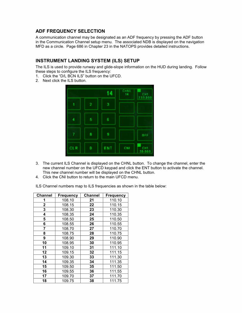
The ILS is used to provide runway and glide-slope information on the HUD during landing. Followthese steps to configure the ILS frequency:1. Click the “D/L BCN ILS” button on the UFCD.2. Next click the ILS button.
3. The current ILS Channel is displayed on the CHNL button. To change the channel, enter thenew channel number on the UFCD keypad and click the ENT button to activate the channel.This new channel number will be displayed on the CHNL button.
4. Click the CNI button to return to the main UFCD menu.
ILS Channel numbers map to ILS frequencies as shown in the table below:
Channel Frequency Channel Frequency
1 108.10 21 110.10
2 108.15 22 110.15
3 108.30 23 110.30
4 108.35 24 110.35
5 108.50 25 110.50
6 108.55 26 110.55
7 108.70 27 110.70
8 108.75 28 110.75
9 108.90 29 110.90
10 108.95 30 110.95
11 109.10 31 111.10
12 109.15 32 111.15
13 109.30 33 111.30
14 109.35 34 111.35
15 109.50 35 111.50
16 109.55 36 111.55
17 109.70 37 111.70
18 109.75 38 111.75

19 109.90 39 111.90
20 109.95 40 111.95
AUTOPILOT SETUP
This add-on supports these autopilot modes:
• BALT – Hold the current barometric altitude (height above sea level)
• RALT – Hold the current radar altitude (height above ground)
• HDG – Hold the current heading
The altitude hold modes may be used in conjunction with the heading hold mode.1. From the main UFCD menu, click the “A/P” button. This will display the various autopilot
modes described above.
2. Click the desired autopilot mode/s.3. Click the CNI button to return to the main UFCD menu.
TACAN SETUP
TACANs may be used for aircraft navigation. By selecting a TACAN channel on the UFCD, thenavigation MFD can be configured to provide navigation information for the selected TACANwhich can also be displayed on the HUD. See the section on the Navigation MFD for moredetails.1. From the main UFCD menu, type in the desired TACAN channel number and click the “TCN”
button. The channel number shown on the button will change to the new channel.
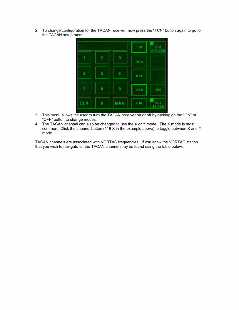
2. To change configuration for the TACAN receiver, now press the “TCN” button again to go tothe TACAN setup menu.
3. This menu allows the user to turn the TACAN receiver on or off by clicking on the “ON” or“OFF” button to change modes.
4. The TACAN channel can also be changed to use the X or Y mode. The X mode is mostcommon. Click the channel button (119 X in the example above) to toggle between X and Ymode.
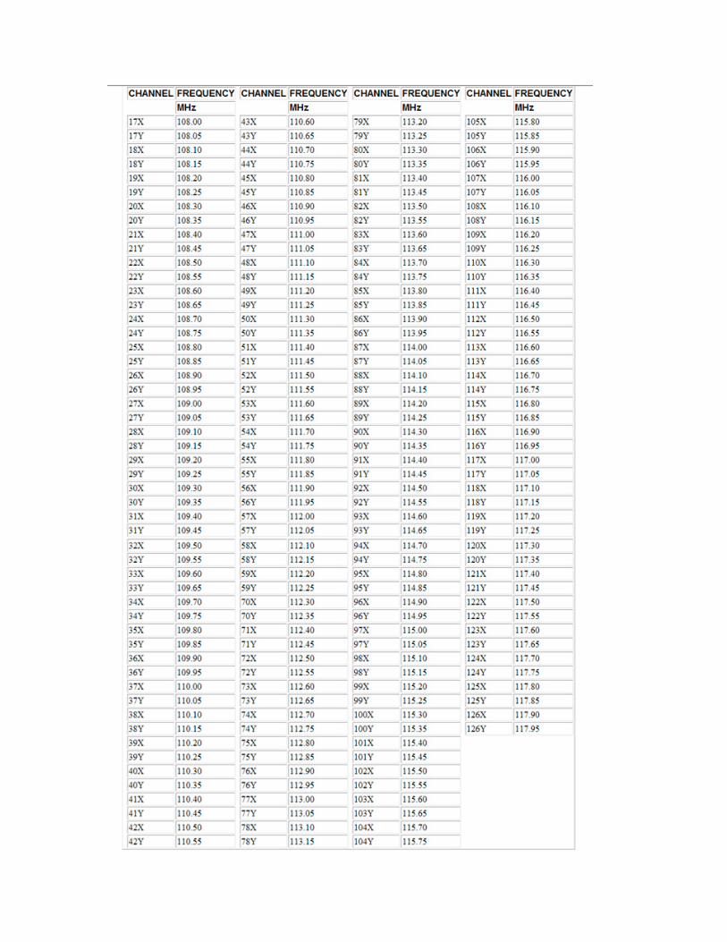
TACAN channels are associated with VORTAC frequencies. If you know the VORTAC stationthat you wish to navigate to, the TACAN channel may be found using the table below:

NAVIGATION MFD
See Chapter 24 in the NATOPS for detailed information on the Navigation MFD and a descriptionof the symbols on page 242. Many of the MFD functions are modeled by this add-on and X-Plane-specific information is described below.
MFD MAP SCALE
The route displayed on the MFD can be shown at different scales of 5 Nm, 10 Nm, 20 Nm, and40 Nm. To cycle though these options, click the SCL button on the top middle of the MFD.
MFD MAP ORIENTATION
The MFD map may be oriented such that the aircraft track is always at the top of the compassrose or North is always at the top. To change the orientation, click the MODE button on themiddle left of the MFD. The current orientation, Track Up (TUP) or North Up (NUP) will be boxed.Click the desired orientation.
ROUTE SELECTION
To see the 2D pop-up of the MFD, press F6. Eight pre-defined routes (also known assequences) can be called up and displayed on the MFD. Two routes are included in this add-on,route 1 and route 3. To fly them, go to the Pensacola NAS airport. They will exist in the “X-Plane/Output/FMS plans” folder. The files must follow the specified naming convention asfollows:
F18_seqX.fms where X is the route number from 1 to 8
Although this plugin does not allow you to define routes, they may be created by hand or by theFMS used in any of the other X-Plane aircraft.
To cycle through the routes, click the SEQX button on the lower right side of the MFD. The firsttime you press the button, the route will become “boxed” meaning that the route will be displayedon the MFD as a dotted line connecting all waypoints together. Pushing the SEQX button againwill cycle to the next route.
WAYPOINT SELECTION
After the route has been selected, waypoints can be cycled through using the up and down arrowbuttons on the right side of the MFD. The waypoint number is shown in between the arrows.Waypoint distance, bearing, and ETA are shown in the upper right corner of the MFD. Thecurrently selected waypoint is shown as a small circle on the MFD.
To show steering info and waypoint distance on the HUD, click the WYPT button on the MFD to“box” it. The waypoint number and distance is shown on the bottom right of the HUD. ACommand Heading Steering Marker line is shown below the heading tape on the HUD (see Page754 in the NATOPS). Turn towards this line until it is centered in the heading tape to fly towardsthe waypoint.
DESIGNATING THE WAYPOINT AS A TARGET
One waypoint along a route may be designated as a target. First select the desired waypointusing the arrow buttons. Then press the WPDSG button on the lower right side of the MFD. TheWYPT MFD text changes to TGT to show that the waypoint is now the designated target. TheWPDSG text also disappears. The waypoint may be undesignated by changing routes.
AUTO WAYPOINT SEQUENCING
To have the MFD automatically switch to the next waypoint upon reaching the current one, clickthe AUTO button on the bottom right of the MFD.
TACAN STEERING INFORMATION
To display TACAN steering and distance information on the HUD, click the TCN button on the topleft of the MFD to “box” it. The TACAN identifier and distance is shown on the bottom right of theHUD. . A Command Heading Steering Marker line is shown below the heading tape on the HUD

(see Page 754 in the NATOPS). Turn towards this line until it is centered in the heading tape tofly towards the TACAN station.
COURSE LINE STEERING
Course line steering and the HUD steering symbology is described in detail starting on page 756of the NATOPS. To activate Course Line Steering, press the F5 key on your keyboard. A courseline will be shown between your aircraft and the currently selected waypoint or TACAN station.Click anywhere on the left or right side of the MFD screen to rotate the CRS line clockwise orcounterclockwise. NOTE – currently this can only be done on the MFD in the virtual cockpit. Itdoes not work on the 2D MFD pop-up. The course line is useful for when you want to approachan airport, for example, at a specific heading to be lined up with the runway. CRS line steeringinfo will be displayed on the bottom right of the MFD. As well, a steering arrow and dots will bedisplayed on the HUD as described in detail in the NATOPS.
HUD
See the NATOPS for detailed descriptions of the HUD modes. Page 247 in the NATOPSdescribes the HUD symbology. The following sections cover what is modeled in this add-on.
ADJUSTMENT CONTROLS
The HUD brightness may adjusted using the brightness knob shown in Figure 2.
The HUD de-clutter switch may be used to reduce the amount of information shown on the HUD.
NAVIGATION MODE
When airborne with no weapons selected, the HUD will default to Navigation mode as shownbelow:
In the screenshot above, the airpseed is 535 knots. The altitude is 8750 ASL and the barometricpressure is 29.93 as set on the manual altimeter. The rate of descent is 660 fpm. The NPATACAN station is selected and is 8.6 Nm away.
LANDING MODE
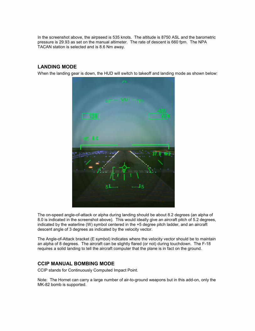
When the landing gear is down, the HUD will switch to takeoff and landing mode as shown below:
The on-speed angle-of-attack or alpha during landing should be about 8.2 degrees (an alpha of8.0 is indicated in the screenshot above). This would ideally give an aircraft pitch of 5.2 degrees,indicated by the waterline (W) symbol centered in the +5 degree pitch ladder, and an aircraftdescent angle of 3 degrees as indicated by the velocity vector.
The Angle-of-Attack bracket (E symbol) indicates where the velocity vector should be to maintainan alpha of 8 degrees. The aircraft can be slightly flared (or not) during touchdown. The F-18requires a solid landing to tell the aircraft computer that the plane is in fact on the ground.
CCIP MANUAL BOMBING MODE
CCIP stands for Continuously Computed Impact Point.
Note: The Hornet can carry a large number of air-to-ground weapons but in this add-on, only theMK-82 bomb is supported.

When the weapon selector switch is set to A-G, CCIP bombing mode will be activated providedthat the current waypoint has not been selected as a target. Unclassified ballistics calculationswith wind compensation are used to calculate the impact point. This impact point is shown as across (+) symbol connected by a steering line drawn down from the velocity vector as shownbelow:
Bombing in this mode is simple. When the impact point symbol is over the target, press theweapon release button to drop the bomb. Pressing CTRL-w on your keyboard will display theflight of the bomb.
There is also Pull-up Bracket (shown above and to the right of the impact symbol in the aboveimage) that is displayed. When the velocity vector intercepts the Pull-up bracket, a 4G pull-upmust be initiated immediately to prevent aircraft impact with the ground.
AUTOMATIC BOMBING MODE
If the waypoint has been designated as a target (see the Navigation MFD section on Designatingthe Waypoint as a Target for information) and when the weapon selector switch is set to A-G,AUTO bombing mode is activated. In this mode, the HUD provides more information to the pilot:
• The target distance and time to bomb release are displayed on the lower right side of theHUD.
• A small diamond is displayed over top of the target in the HUD for easy target identification
• An Azimuth Steering Line (ASL) is displayed vertically on the HUD. The velocity vector mustbe kept centered on this line to ensure that the bomb impacts the target. This is wind-compensated as well.
• A Release Cue horizontal line appears at the top of the ASL 10 seconds from bomb release.This line will move down the ASL and when it intersects the velocity vector, the weapon

release button should be pressed. Ctrl-w may be pressed on your keyboard to view the flightof the bomb.
The above two images show the HUD in AUTO bomb release mode. In the first image, adiamond is shown above the target, in this case a VOR station. The target is 3.6 Nm away andtime to bomb release is 15 seconds. In the second image, the target is no longer in view but thatis fine. The velocity vector is nearly centered on the ASL as it should be. There are 3 seconds tobomb release and the Release Cue line is moving down the ASL, 3 seconds from intersecting thevelocity vector at which point it is time to drop the bomb.
NOTE: An X-Plane bug prevents automatic dropping of the bomb. The way it should work andhopefully will at some point is that once the release cue line appears, the pilot can press theweapon release button at any time. When the release cue intercepts the velocity vector, thebomb will drop automatically as long as the pilot still has the weapon release button pressed.
QUESTIONS? COMMENTS?Send an e-mail to me at [email protected] if you have any questions or comments or bugreports in regards to this plugin.
Look for a full-blown release at a later time!