f 312 - euroformulaopen.net · front suspension 11 suspensión delantera 11 ... -assembly in three...
TRANSCRIPT

F 312
Owners Manual / Manual de Usuario
European F3 Open Technical Comision Comisión Técnica del European F3 Open 1/52
Version 1 of 13 rd September 2012 Versión 1 de 13 de Septiembre de 2012
Contents / Contenido
Introduction 3 Introducción 3
General views of the 312 4 Vistas generales del 312 4
General specifications and suppliers 5 Especificaciones generales y suministradores 5
Suggested set-up for DUNLOP tyre 6 Set-up inicial para neumático DUNLOP 6
Adjustments 8 Ajustes 8
Steering 9 Dirección 9
Front suspension 11 Suspensión delantera 11
-Roll Center 11 -Centro de Balanceo 11
-Vertical preload adjustment 12 -Ajuste de la precarga vertical 12
-Front torsion bar pre-load 12 -Precarga de las barras de torsión delanteras 12
Springs 13 Muelles 13
-Front ratio 13 -Relación delantera 13
-Rear springs 14 -Muelles traseros 14
Front castor angle setting 14 Ajuste del ángulo de avance delantero 14
Rear castor angle setting 15 Ajuste del ángulo de avance trasero 15
Front anti-roll / Front pushrod 16 Anti-balanceo delantero / Pushrod delantero 16
Front anti-roll bar values 18 Valores de la barra anti-balanceo delantera 18
Rear anti-roll bar 20 Barras anti-balanceo traseras 20
Front and rear suspension 22 Suspensión delantera y trasera 22
-Front suspension geometry 23 -Geometría de suspensión delantera 23
-Rear suspension geometry 24 -Geometría de suspensión trasera 24
Dampers 25 Amortiguadores 25
Differential 27 Diferencial 27
-Differential lock 29 -Tarado de diferencial 29
-Differential lay-out 29 -Esquema del diferencial 29
Aerodinamics 31 Aerodinámica 31
-Front wing 31 -Ala delantera 31
-Rear wing 33 -Ala trasera 33
-Rear lower wing pillars 34 -Soportes del perfil inferior del ala trasera 34
-Configurations 35 -Configuraciones 35
-Balance of the car 36 -Equilibrado del vehículo 36
-Front blanking 36 -Regulación entrada de aire 36
-Rear blanking 37 -Regulación salida de aire 37
Front and rear upright 38 Manguetas delantera y trasera 38
-Wheel nut safety clip 39 -Clip de seguridad de fijación de ruedas 39
Front upright 39 Mangueta delantera 39
-Assembly in three steps 39 -Montaje en tres etapas 39
-Bearing removal 40 -Desmontaje del rodamiento 40
Rear upright 41 Mangueta trasera 41

F 312
Owners Manual / Manual de Usuario
European F3 Open Technical Comision Comisión Técnica del European F3 Open 2/52
Version 1 of 13 rd September 2012 Versión 1 de 13 de Septiembre de 2012
-Assembly in three steps 41 -Montaje en tres etapas 41
-Bearing removal 42 -Desmontaje del rodamiento 42
Others 43 Otros 43
-Engine oil level 43 -Nivel de aceite de motor 43
-Fuel tank system 44 -Depósito de gasolina 44
-2012 F3 FIA Structure Testing record 45 -Test FIA de la estructura 2012 45
-Mileage of parts 49 -Duración de las piezas 49
-Mirrors 50 -Retrovisores 50
-Starter 50 -Motor de arranque 50
-Transmision ratios 51 -Relaciones de transmisión 51
-Brake pads 52 -Pastillas de freno 52
-Brake master cilinders 52 -Bombas de freno 52
-Clutch 52 -Embrague 52
-Entertainment modifications 53 -Modificaciones para la explotación 53

F 312
Owners Manual / Manual de Usuario
European F3 Open Technical Comision Comisión Técnica del European F3 Open 3/52
Version 1 of 13 rd September 2012 Versión 1 de 13 de Septiembre de 2012
INTRODUCTION The F-312 is a F3 chasis that has been designed and manufactured by Dallara Automobili and is, with the F-308, the only one that is authorized to participate at the European F3 Open, within the configuration that is described in this manual. It is not authorized, unless any other stated, any modification of any or the parts that have been delivered with the vehicle. Whatever non authorized modification will inmediatelly mean that the car is not according to the technical regulations. For any doubt, enquiry or suggestion, please do not hesitate to contact with the Organizer and Promoter of the Championship.
GT Sport Organización S. L. C/ Juan Bravo nº 17, Bajo derecha
Madrid 280006 Tel:91 432 27 50 Fax: 91 578 05 82 Fax:91 426 35 96 www.gtsport.es
Sporty manager: D. José Miguel García Galán Spare parts manager: D. Luis Mayoral All the spare parts orders that are necessary to properly entertain and mainten the vehicle, would be done through the Organizer and Promoter of the Championship.
INTRODUCCION El chasis de fórmula 3 F-312 ha sido fabricado por Dallara Automobili y es junto con el F-308 el único autorizado para participar en el European F3 Open, en la configuración que se describe en éste manual. No se autoriza, salvo indicación contraria, modificación alguna de ninguna de las piezas suministradas con el vehículo. Cualquier modificación no autorizada sopondrá la no conformidad con el reglamento técnico. Para cualquier duda, consulta, aclaración o sugerencia, por favor no duden en contactar con el Organizador y Promotor del Campeonato:
GT Sport Organización S. L. C/ Juan Bravo nº 17, Bajo derecha
Madrid 280006 Tel:91 432 27 50 Fax: 91 578 05 82 Fax:91 426 35 96 www.gtsport.es
Responsable Deportivo: D. José Miguel García Galán Responsable de Recambios: D. Luis Mayoral Los pedidos de las piezas de recambio necesarias para la correcta reparación y o mantenimiento de los vehículos del campeonato, se realizará a través del Organizador y Promotor del Campeonato:
F 312
Owners Manual / Manual de Usuario
European F3 Open Technical Comision Comisión Técnica del European F3 Open 4/52
Version 1 of 13 rd September 2012 Versión 1 de 13 de Septiembre de 2012
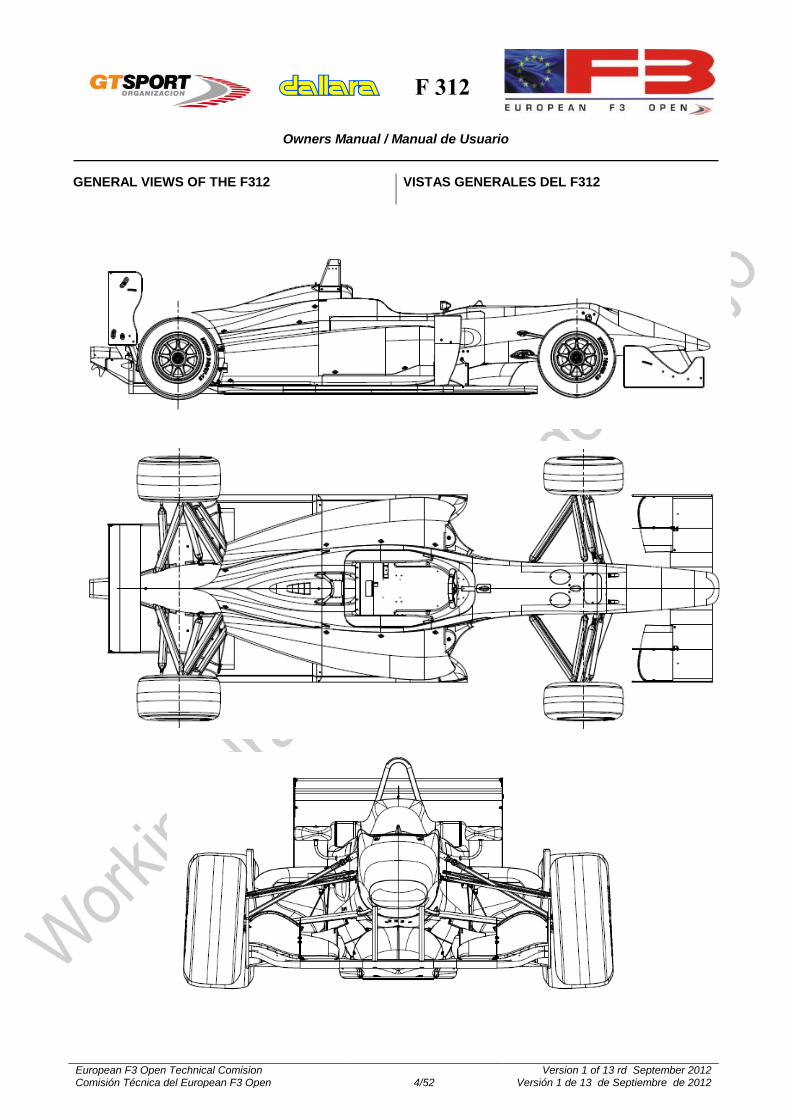
GENERAL VIEWS OF THE F312
VISTAS GENERALES DEL F312

F 312
Owners Manual / Manual de Usuario
European F3 Open Technical Comision Comisión Técnica del European F3 Open 5/52
Version 1 of 13 rd September 2012 Versión 1 de 13 de Septiembre de 2012
GENERAL CHARACTERISTICS AND SUPPLIERS
CARACTERISTICAS Y SUMINISTRADORES
Wheelbase 2800 mm Distancia entre ejes 2800 mm
Front track 1595 mm Vía delantera 1595 mm
Rear track 1540 mm Vía trasera 1540 mm
Overall length 4351 mm Longitud total 4351 mm)
Overall width 1845 mm [includes tires] Anchura total 1825 mm
Overall height 945 mm [plus ride height] Altura total 945 mm (Más la altura libre al suelo)
Weight 570 kg incl. driver & ballast Peso 575 Kg (con piloto y lastre)
Front suspension pushrod twin damper system with torsion
bar springs Suspensión delantera
Push-rod con doble-amortiguador y barras de torsión.
Rear suspension pushrod twin damper system with coil
springs Suspensión trasera
push-rod con doble amortiguador y muelles helicoidales.
Chassis carbon sandwich with AL/Nomextm
honeycomb Chasis
Sandwich de Carbono con panel “nido
de abeja” de tipo AL / NOMEX
Bodywork Glass fibre composite with Nomextm
honeycomb Carrocería
Fibra de vidrio pre-impregnada con panel “nido de abeja” de NOMEX
Gearbox Hewland, sequential, six forward gears +
reverse Caja de cambios
HEWLAND, secuencial, seis relaciones y M. A.
G-box internals Hewland gears and power-flow differential Relaciones de cambio y diferencial
HEWLAND
Springs Dallara torsion bar springs and 3“/36mm ID
coils Muelles
Barras de Torsión Dallara, y EIBACH de 3”/36 mm de diámetro interior
Dampers Koni 2812 bump and rebound adjustable Amortiguadores KONI 2812 (regulables en compresión y
extensión)
Fuel cell Premier – FT3 Depósito de combustible
PREMIER – FT3
Extinguisher OMP (electric operated) Sistema de extinción OMP (accionamiento eléctrico)
Steering wheel OMP Volante OMP
Quick release SPA-Design Sistema de desmontaje rápido del volante
SPA design
Wheels OZ 9”front & 10.5”rear Llantas OZ - delanteras 9” x 13 y
traseras 10.5 x 13
Brakes Brembo Sistema de frenos BREMBO
Battery Deka Batería DEKA ref. DEAKETX 30 L
Seat belts OMP Cinturón de seguridad
OMP
Engine 3SGE Toyota, specific for European F3
Open Motor
Toyota 3SGE, específico para el European F3 Open

F 312
Owners Manual / Manual de Usuario
European F3 Open Technical Comision Comisión Técnica del European F3 Open 6/52
Version 1 of 13 rd September 2012 Versión 1 de 13 de Septiembre de 2012
SUGGESTED SET-UP FOR DUNLOP TYRE
SET-UP INICIAL PARA NEUMATICO DUNLOP
Front
Delantero
Ride height (mm) 16 Altura al suelo (mm) 16
Spring 20 Nm/deg Muelles 20 Nm/º
Spring Pre-load Without Precarga de muelle Sin
Pushrod Lenght Use the pushrod adjuster to set the ride
height Long. Pushrod Utilizar para ajustar la altura al suelo
Roll Center Setting
Std. Setting C. de Balanceo
Std.
ARB (Kg/mm) 60 Kg/mm Barra anti-balanceo 60 Kg/mm
Camber 3,50º Caída 3,50º
Caster-UMP/P-15 16,00º Avance-UMP/P-15 16,00º
Toe (mm total) 3,00 out Convergencia 3,00 divergencia
Rear Trasero
Ride height (mm) 35 Altura al suelo (mm) 35
Spring (Lb/in) 850 Muelles (Lb/in) 850
Spring Pre-load Without Precarga de muelle Without
Pushrod Lenght Use the pushrod adjuster to set the ride
height Long. Pushrod
Use the pushrod adjuster to set the ride height
Roll Center Setting
A-1 Setting C. de Balanceo
A-1
ARB (Kg/mm) 90 Kg/mm Barra anti-balanceo 90 Kg/mm
Camber 2,50º Caída 2,50º
Toe (mm total) 2,00 in Convergencia 2,00 convergencia
Differential 60/80 4F Avance-UMP/P-15 60/80 4F

F 312
Owners Manual / Manual de Usuario
European F3 Open Technical Comision Comisión Técnica del European F3 Open 7/52
Version 1 of 13 rd September 2012 Versión 1 de 13 de Septiembre de 2012
Notes Ride heights are measured at the axles When using spring pre-load you can lower
the front ride height Caster UMP/P-15 means caster on the
suspension with the pushrod mounted on the upright, in position P-15 [see later in the manual]
Toe is measured at the wheel rim’s, total value means LH and RH wheels added
Differential, see following pages.
General comments on car set-up In fast corners aerodynamics (ride heights
and wing settings) have more influence on the balance than in slower corners.
The weight distribution is important in slow and fast corners and together with the differential settings these are the most important contributors to the mechanical balance of the car.
Tune the dampers to the chosen springs, not the springs to the dampers.
Cold race tyres will not be able to generate the required grip. No car can reach its limit on too cold tyres. Neither a car can be reasonably balanced with a significant difference between front and rear tyre temperatures.
Run the car always as low as possible, although without going stiffer on springs for running lower
Notas Las alturas se miden en los ejes Al usar precarga delantera, se puede
disminuir la altura delantera Avance UMP/P-15 significa el avance en la
suspensión, con el pushrod montado en la mangueta, en la posición P-15 [consultar manual más adelante].
La convergencia se mide en las llantas, y el valor total es la suma de ambas ruedas
Diferencial, ver las páginas siguientes
General comments on car set-up En curvas rápidas, la aerodinámica (alturas y
ala) tienen más influencia en el comportamiento que en curvas lentas.
La distribución de pesos es importante en curvas lentas y rápidas, y junto con el reglaje del diferencial, es lo más importante para el equilibrio dinámico del coche.
Ajuste los amortiguadores a los muelles elegidos, no a la inversa.
Las ruedas frías no son capaces de generar el suficiente agarre. Ningún coche puede alcanzar su límite con ruedas frías. De igual modo, en el coche tampoco se puede conseguir una puesta a punto razonable con diferencia importante entre las temperaturas de las ruedas de los ejes delantero y trasero.
Ruede con el coche siempre tan bajo como se pueda, sin llegar a montar muelles más rígidos únicamente para conseguir rodar más bajo

F 312
Owners Manual / Manual de Usuario
European F3 Open Technical Comision Comisión Técnica del European F3 Open 8/52
Version 1 of 13 rd September 2012 Versión 1 de 13 de Septiembre de 2012
ADJUSTMENTS
AJUSTES
Positive
change in Means
Variación
positiva en:
Significa:
Height Car rises Altura Subida de carrocería
Toe Toe-out Convergencia Divergencia
Camber Upper part of rim outward Caída Parte superior de la rueda hacia fuera
Castor Lower part of the upright points ahead Avance Punto inferior de la mangueta hacia
delante
FRONT / DELANTERO REAR / TRASERO
PUSHROD ADJUSTER / AJUSTE PUSHROD Height change/ Cambio Altura
(mm) 5.663 6.082
1TURN / 1 VUELTA Camber change /Cambio caída (deg)
10’30” 11’17”
Thread step /Paso rosca 24/”R+24/”L=2.12 mm 20/”R+24/''L=2.33 mm
TOE ADJUSTER (PER WHEEL) / AJUSTE CONVERGENCIA
Height change /Variación Altura -3.33 mm
Camber change / Variación Caída -19’
1TURN / 1 VUELTA Toe change / Cambio Convergencia (deg)
38’42” -46’30”
Thread step / Paso rosca 24/”=1.06 mm 20/”R+24/”L=2.33 mm
CAMBER SPACER/ CALA DE CAÍDA
+1mm
Height change / Variación Altura
Toe change / Variación Conv.
26’46”
0.27 mm
23’20”
1.98 mm
12’= + ¼ Turn(+0.61 mm)
CASTOR ADJUSTER / AJUSTE DE AVANCE 23° on reference /En ref. =17.1° Castor change Variación Avance(º) 30’58” -46’48” Thread step Paso de rosca 24/''=1.06 mm 20/''= 1.27 mm
1TURN Height Change (mm) Var. Altura (mm) -0.86 -1.55 Camber change (deg) Variación Caída (º) -10'5” 1'30” Toe change (deg) Variación Conv. (º) 7’26”=-1/5 turn -0.2 mm
-1'44”
SPRING PLATFORM / COPELA MUELLE
+1TURN Thread step (mm) Paso de rosca (mm) 2
Height change (mm) Var. Altura (mm) 2.586
WHEEL to DAMPER / REL. RUEDA a AMORTIGUADOR 1.390 1.30 (See table / Ver tabla)
WHEEL to SPRING / REL. RUEDA a MUELLE (vertical) See table / Ver tabla 1.30 (See table / Ver Tabla)
WHEEL to ARB / REL. RUEDA a BARRA ANTI-BAL. See table / Ver Tabla See table / Ver Tabla
ROLL CENTRE HEIGHT / ALTURA CENTRO BALANCEO Tyre dependent/ Dep. neumático Tyre dependent / Dep. neumático

F 312
Owners Manual / Manual de Usuario
European F3 Open Technical Comision Comisión Técnica del European F3 Open 9/52
Version 1 of 13 rd September 2012 Versión 1 de 13 de Septiembre de 2012
STEERING
DIRECCION
Pinion primitive diameter 15.60 mm Diámetro primitivo del piñón 15.60 mm
Static steering ratio 12.5° steering wheel/1°wheel Relación de giro estática 12.5° de volante/1° rueda
Ackermann [%] 28 Ackermann [%] 28
Spacers to adjust camber are available in the following thickness: FRONT: 1.0, 1.5 and 2.0 mm. REAR: 0.8, 1.0, 1.2, 1.5 and 2.0mm. Combine these to make fine adjustments.
Front and rear wheel to spring, front and rear wheel to drop link motion ratios may be considered near constant for typical wheel travel.
The front roll centre is adjustable by moving the appropriate spacer (see lower wishbone). More information further in this manual.
Se dispone de calas de reglaje de caída para el eje delantero de espesores 1, 1.5 y 2.0 mm. Para el eje trasero, se dispone de calas de 0.8, 1, 1.2, 1.5 y 2.0 mm. Para obtener reglajes precisos, se han de combinar distintas calas.
Las relaciones de movimiento rueda trasera a muelle, así como las de las ruedas delantera y trasera a bieletas, se pueden considerar constantes para todo el recorrido típico de las ruedas.
El centro de balanceo delantero es ajustable mediante la selección del separador adecuado (ver triángulo inferior). Más informacion en otros apartados del manual.

F 312
Owners Manual / Manual de Usuario
European F3 Open Technical Comision Comisión Técnica del European F3 Open 10/52
Version 1 of 13 rd September 2012 Versión 1 de 13 de Septiembre de 2012
Steering column Columna de dirección
In case you need to shorten the steering column please, attentively respect these dimensions
NOTE: ONLY use the first generation re-enforced version (upgrade steering racks 04/2012) or the second generation steering rack. DO NOT use the first generation in its original not re-enforced version.
En caso de necesitar acortar la columna de dirección, hay que respetar las siguientes dimensiones.
NOTA: Utilice SÓLO la cremallera de dirección de la versión inicial reforzada, o la segunda evolución (04/2012). NO use la primera generación sin reforzar.

F 312
Owners Manual / Manual de Usuario
European F3 Open Technical Comision Comisión Técnica del European F3 Open 11/52
Version 1 of 13 rd September 2012 Versión 1 de 13 de Septiembre de 2012
FRONT SUSPENSION
SUSPENSIÓN DELANTERA
STANDARD POSITION - 4 ESTANDARD POSICIÓN -4
Roll Center Centro de Balanceo
The Front roll centre height can be changed by moving the spacer relative to the wishbone spherical joint.
When you change to a one step ´higher roll centre´ configuration the push-rod length has to be shortened by 1/12 register turns ( ≈0.5 face of the adjuster) to put the car back at the same front ride height.
When adjusting the roll centre height camber gain versus wheel travel varies a little
La altura del centro de balanceo delantero puede regularse mediante los casquillos de posicionamiento de la rótula del triángulo de suspensión
Al aumentar la altura del centro de balanceo un paso, la longitud del push-rod tiene que acortarse aproximadamente en 1/12 de vuelta del regulador (media cara), para dejar el coche en la misma altura delantera.
Cuando se ajusta la altura del centro de balanceo, la variación de caída con la altura, varía ligeramente.
Spacer / Casquillo
Roll centre height @ static ride height /
Altura Centro Balanceo con altura estática
Camber change with 10mm travel / Variación caída con 10 mm de variación
Std / Estandar
d 6mm below X 18’
-2mm
4mm below + 2mm top /
4 mm inferior y 2 mm superior
+9.4mm 16’
-4mm
2mm below + 4mm top/
2 mm inferior y 4 mm superior
+18.5mm 15’
-6mm 6mm top /
6 mm superior +27.2mm 14’

F 312
Owners Manual / Manual de Usuario
European F3 Open Technical Comision Comisión Técnica del European F3 Open 12/52
Version 1 of 13 rd September 2012 Versión 1 de 13 de Septiembre de 2012
Vertical preload adjustment Ajuste de la precarga vertical
In a non pre-load condition, as long as the damper is not fully extended, turning on the spring changes the car ride height (and lowers the gas pressure inside the damper). When the damper gets fully extended, turning on the spring increases vertical spring pre-load on the car. We advise though, not to proceed this way, because some dampers [including Koni] should not be used fully extended. Therefore we advise to use the droop-stop for both limiting rebound travel and/or applying spring pre-load. Pre-load in this text is considered to be the necessary force that has to be applied to the spring to change:
its angle with respect to the position at static ride height, for the front
its length with respect to the static length value, for the rear
Remind that we strongly suggest not to use spring pre-load on the rear axle.
Note: Dampers always have some ‘pre-load’: typically this is 24-27kg for the standard Koni damper. This ‘pre-load’ depends on damper make/type and comes mainly from the internal gas pressure and the level of stiction (minimum force needed to enable relative motion).
Cuando no existe precarga, mientras el amortiguador no está completamente extendido, al girar el muelle (barra de torsión) aumenta la altura de casco y disminuye ligeramente la presión interna del gas del amortiguador. Cuando el amortiguador está completamente extendido, al girar el muelle (barra de torsión) se consigue precarga. Sin embargo, NO se ha de proceder así, ya que el amortiguador no debe trabajar completamente extendido. Por lo tanto, es necesario utilizar el tope regulable tanto para evitar la extensión completa del amortiguador, como para conseguir precarga. Se considera la precarga a aplicar al elemento elástido de la suspensión como la fuerza que se ha de aplicar para variar:
Su ángulo respecto a su posición a la altura estática, para el eje delantero
Su longitud respecto a la longitud para la altura estática, para el eje trasero.
Recuerde que se sugiere muy especialmente no usar precarga en el eje trasero.
Nota: Los amortiguadores siempre tienen cierta «precarga», del orden de 24 – 27kg para el amortiguador Koni. Este es un valor que depende del amortiguador, principalmente de la presión interna y de la fricción de sus componentes (mínima fuerza a aplicar para conseguir movimiento relativo)
Front torsion bar pre-load Precarga de las barras de torsión delanteras
1. Set the car’s ride height adjusting the
pushrod length, with the driver on board.
2. Bring the droop stop in contact with the
rocker (on the side of the monocoque);
3. Set the desired pre-load (see front end of the
torsion bar) and tighten the lock nuts.
1. Ajustar la altura al suelo del coche mediante
la regulación de la longitud del pushrod, con
el piloto a bordo.
2. Poner el tope de recorrido en contacto con el
balancín (en el lado del monocasco)
3. Regular la precarga deseada (ver parte
delantera de la barra de torsión), y apretar
las contratuercas.

F 312
Owners Manual / Manual de Usuario
European F3 Open Technical Comision Comisión Técnica del European F3 Open 13/52
Version 1 of 13 rd September 2012 Versión 1 de 13 de Septiembre de 2012
SPRINGS
MUELLES
Front Stiffness / Rigidez Delantera
Max Preload / Máxima
Precarga
Torsion Bar OD / Diámetro exterior barra de torsión
Max Damper Travel / Carrera máxima amort.
Necessary Bump Stop at Damper
(mounted standard)
/ Tope necesario
Max Wheel Travel / Máximo rec. de rueda
F312 Stiffness
@ Torsion Spring / Rigidez
Barra F312
Stiffness @ Ground /
Rigidez en rueda
F308 Stifness @ Strut / Rigidez en F308
[N-m/deg] [N/mm] [lb/in] [lb/in] [deg] [mm] [mm] [mm] [mm]
11,0 71,8 410,2 523,8 6 12,15 23,0 6,0 31,6
12,5 81,6 466,1 595,2 6 12,54 23,0 6,0 31,6
14,0 91,4 522,1 666,7 6 12,90 23,0 6,0 31,6
15,5 101,2 578,0 738,1 6 13,25 23,0 6,0 31,6
17,0 111,0 634,0 809,5 6 13,57 23,0 6,0 31,6
18,5 120,8 689,9 881,0 6 13,87 23,0 6,0 31,6
20,0 130,6 745,8 952,4 6 14,16 23,0 6,0 31,6
21,5 140,4 801,8 1023,8 6 14,44 23,0 6,0 31,6
23,0 150,2 857,8 1095,3 6 14,70 23,0 6,0 31,6
24,5 160,0 913,7 1166,7 6 14,96 23,0 6,0 31,6
Front TORSION BAR springs listed and compared to
the coil springs on the F308 car
Características de las barras de torsión delanteras, comparadas con las de los resortes helicoidales del F308.
Front Ratio: The ratio can be seen as wheel travel in
mm to spring twist in degrees. Relevant is their
stiffness at ground which is seen in this table and
compared with the same on the previous car, the
F308.
Relación Delantera: La relación de movimiento debe
entenderse como mm de desplazamiento de rueda,
respecto a giro de la barra en grados. En todo caso,
lo relevante es la rigidez en la rueda, comparado con
el coche anterior (F 308)
PUSH ROD
DROOP STOP
PRE-LOAD ADJUSTER
LOCK NUTS TUER

F 312
Owners Manual / Manual de Usuario
European F3 Open Technical Comision Comisión Técnica del European F3 Open 14/52
Version 1 of 13 rd September 2012 Versión 1 de 13 de Septiembre de 2012
FRONT CASTOR ANGLE SETTING
AJUSTE DEL AVANCE DELANTERO
Rear Springs: The rear springs are the same coil
springs as used on the previous F308 car
Muelles traseros: Los muelles traseros son los
mismos que en el coche previo (F308)
When the car is flat, that is with the same front and rear ride height:
Measure the apparent castor angle and compare this with the following: when the upright inclination angle (apparent castor) is -6.8° the castor angle (build in castor) is 16.1°. The upright reference plane points upwards in forward direction.
When the car has a pitch angle, that is with different front and rear ride height:
For instance, with FRH 18mm and RRH 40mm the pitch angle equals:
[(40-18)/2800] x 57.29 = 0.45°
The upright inclination angle (apparent castor) is -6.80° + 0.45° = 6.35° and the castor angle (build in castor) becomes 16.10° - 0.45° = 15.65°
Cuando el vehículo está completamente plano, (altura de casco delantera y trasera iguales) :
Medir el avance aparente y compararlo con lo siguiente: cuando la inclinación de la mangueta (avance aparente) es de -6.8º, el ángulo de avance (real) es de 16.1º. La referencia del plano de la mangueta es hacia delante.
Con alturas de casco diferentes en el eje delantero y en el eje trasero, el ángulo de avance varía debido al “cabeceo” del vehículo. Como valor de referencia, con 18 mm. de altura de casco delantera y 40 mm. de altura de casco trasera, el ángulo de cabeceo es de 2.03º (ya que la distancia entre ejes es de 2800 mm.).
Por tanto, el ángulo de inclinación de la mangueta (avance aparente) es -6.80° + 0.45° = 6.35° y el avance real es 16.10° - 0.45° = 15.65°
CASTOR /AVANCE 16.1°
HORIZONTAL MEASURED ANGLE / ÁNGULO
MEDIDO -6.8° PLA
NE TRAVEL DIRECTION /
DIRECCIÓN DE AVANCE
F 312
Owners Manual / Manual de Usuario
European F3 Open Technical Comision Comisión Técnica del European F3 Open 15/52
Version 1 of 13 rd September 2012 Versión 1 de 13 de Septiembre de 2012
REAR CASTOR ANGLE SETTING
AJUSTE DEL AVANCE TRASERO
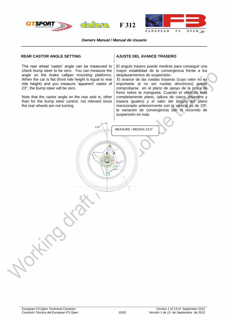
The rear wheel ‘castor’ angle can be measured to check bump steer to be zero. You can measure the angle on the brake calliper mounting platforms. When the car is flat (front ride height is equal to rear ride height) and you measure ‘apparent’ castor of 23°, the bump steer will be zero. Note that the castor angle on the rear axle is, other than for the bump steer control, not relevant since the rear wheels are not turning.
El angulo trasero puede medirse para conseguir una mayor estabilidad de la convergencia frente a los desplazamientos de suspensión. El avance de las ruedas traseras (cuyo valor no es importante al no ser ruedas directrices) puede comprobarse en el plano de apoyo de la pinza de freno sobre la mangueta. Cuando el vehículo está completamente plano, (altura de casco delantera y trasera iguales) y el valor del ángulo del plano mencionado anteriormente con la vertical es de 23º, la variación de convergencia con el recorrido de suspensión es nula.
MEASURE / MEDIDA 23.0°

F 312
Owners Manual / Manual de Usuario
European F3 Open Technical Comision Comisión Técnica del European F3 Open 16/52
Version 1 of 13 rd September 2012 Versión 1 de 13 de Septiembre de 2012
FRONT ANTI-ROLL / FRONT PUSHROD
ANTIBALANCEO DELANTERO / PUSHROD
DELANTEROS
Lay-out of different FARB
Esquema de las diferentes soluciones antibalanceo delanteras.
Views of different FARB fittings.
Vistas de las distintas fijaciones de las barras anti-balanceo delanteras

F 312
Owners Manual / Manual de Usuario
European F3 Open Technical Comision Comisión Técnica del European F3 Open 17/52
Version 1 of 13 rd September 2012 Versión 1 de 13 de Septiembre de 2012
Front pushrod positions.
Posición de los pushrod delanteros
The direction of the arrow and the hole position define the effect /
La dirección de la flecha y la posición del orificio, define el
efecto
FRONT PUSHROD POSITIONS /POSICIONES PUSHROD
DELANTEROS
load transfer /
transferencia de carga
1 P-22 -72%
2 P-27 Reference / Referencia
3 P-32 +72%
4 P-37 +144%
one bracket serves for all 4 positions, 1 and 3 with the arrow pointing forward; 2 and 4 with the
arrow pointing backwards / El mismo soporte sirve para las 4 posiciones, 1 y 3 con la flecha en
dirección a la del avance, 2 y 4 con la flecha en dirección contraria a la
del avance.
The F312 has UMP type front suspension [Upright Mounted Pushrod]: the pushrod is mounted on the upright. The pushrod position is adjustable in longitudinal sense. Extra load is transferred to the corner front inner wheel, potentially reducing under-steer thanks to a more equal vertical load between front inner and outer wheels.
Please, note that the higher the value the more the steering force increases. Load transfer at the rear axle increases accordingly, but in the opposite direction, the inner wheel gets unloaded.
With P-27 (reference) the vertical motion difference between outer and inner wheel, at near full steering lock (31 mm rack travel), is 9.08 mm.
El F312 tiene suspensión de tipo UMP (pushrod montados en la mangueta). La posición del pushrod es ajustable en sentido longitudinal. Se transfiere carga extra a la rueda delantera interna, reduciendo potencialmente el subviraje, gracias a una mayor igualdad en la carga vertical entre la rueda interna y la externa.
Es importante considerar que, cuanto mayor es el valor, mayor es el esfuerzo necesario para el giro de la dirección. La transferencia de carga en el eje trasero aumenta consecuentemente, pero en sentido contrario, la rueda interna se descarga.
Con P-27 (valor de referencia), la diferencia de movimiento vertical entre la rueda externa y la interna, a final de carrera de dirección (31 mm de desplazamiento de cremallera) es de 9.08 mm.
CAR TRAVEL DIRECTION / DIRECCIÓN DE AVANCE

F 312
Owners Manual / Manual de Usuario
European F3 Open Technical Comision Comisión Técnica del European F3 Open 18/52
Version 1 of 13 rd September 2012 Versión 1 de 13 de Septiembre de 2012
FRONT ANTI-ROLL BAR VALUES
VALORES DE LAS BARRAS ANTI-BALANCEO
DELANTERAS
Twin blade FARB / Barra de doble bieleta:
Stiffness @ Droplink / Rigidez en unión
Blade Position / Posición
bieleta
U Φ15 solid - blade 208.50
/ U Φ15 macizo
- bieleta 208.50
U Φ18 solid - blade 208.50
/ U Φ85 macizo
- bieleta 208.50
U Φ 30 x 3 - blade 208.50
/ U Φ 30 x 3 -
bieleta 208.50
U Φ15 solid - blade 171.00
/ U Φ15 macizo
- bieleta 171.00
U Φ18 solid - blade 171.00
/ U Φ18 macizo
- bieleta 171.00
U Φ 30 x 3 - blade 171.00
/ U Φ 30 x 3 -
bieleta 171.00
U Φ15 solid - blade 110.83
/ U Φ15 macizo
- bieleta 110.83
U Φ18 solid - blade 110.83
/ U Φ18 macizo
- bieleta 110.83
U Φ 30x3 - blade 110.83
/ U Φ 30 x 3 -
bieleta 110.83
ARB type / Tipo Barra
31255202 31255413 31255396 31255202 31255413 31255396 31255202 31255413 31255396
ARB code / Código Barra
F31206E005 F31206E004 F31206E003 F31206E005 F31206E004 F31206E003 F31206E005 F31206E004 F31206E003
BLADE type / Tipo Bieleta
31255406 31255406 31255406 31255409 31255409 31255409 31255408 31255408 31255408
BLADE code / Código Bieleta
F31206E008 F31206E008 F31206E008 F31206E007 F31206E007 F31206E007 F31206E009 F31206E009 F31206E009
[--] [kg/mm] [kg/mm] [kg/mm] [kg/mm] [kg/mm] [kg/mm] [kg/mm] [kg/mm] [kg/mm]
1 - 1 4,3 4,7 5,0 19,4 25,0 31,5 89,5 130,1 194,0
1 - 2 5,3 5,8 6,3 21,6 28,6 37,5 94,0 139,8 216,3
1 - 3 6,2 7,0 7,7 23,8 32,7 44,9 99,8 153,0 249,6
1 - 4 6,6 7,5 8,3 24,8 34,6 48,4 102,7 160,0 268,9
1 - 5 6,7 7,6 8,5 25,0 35,1 49,4 103,6 162,0 274,7
2 - 2 6,7 7,7 8,6 24,3 33,5 46,4 98,9 150,9 244,3
2 - 3 8,3 9,8 11,3 27,1 39,3 58,3 105,4 166,5 287,7
2 - 4 9,0 10,8 12,6 28,4 42,0 64,4 108,7 174,8 313,7
2 - 5 9,2 11,1 13,0 28,7 42,8 66,2 109,6 177,3 321,6
3 - 3 10,8 13,6 16,7 30,8 47,5 78,3 112,7 185,6 350,0
3 - 4 12,0 15,6 19,7 32,4 51,5 89,8 116,5 196,0 389,1
3 - 5 12,4 16,1 20,7 32,9 52,6 93,3 117,6 199,1 401,4
4 - 4 13,6 18,2 24,3 34,3 56,2 105,3 120,5 207,7 438,1
4 - 5 14,0 19,0 25,7 34,8 57,6 110,1 121,7 211,2 453,7
5 - 5 14,5 19,9 27,3 35,3 59,0 115,3 122,9 214,7 470,4
T-bar type FARB / Barra tipo T:
Stiffness @ Droplink /Rigidez en unión
Blade Position / Posición Bieleta
T Φ28x2.0 - (WIDE/ ANCHO)
T Φ28x2.0 - (NARROW / ESTRECHO)
[--] [kg/mm] [kg/mm]
BLADE type / Tipo bieleta
31255414
blade code / Código bieleta
F31206E002
1 123,2 234,2
2 164,5 314,0
3 214,2 410,8
4 237,9 457,3
5 244,4 470,2
This table show FARB stiffness values [FARB Component Stiffness] with one blade forced to displace 1 mm. The other blades is blocked.
Esta tabla muestra los valores de rigidez de las barras anti-balanceo delanteras, con una bieleta bloqueada y un desplazamiento de 1 mm en el extremo de la otra.

F 312
Owners Manual / Manual de Usuario
European F3 Open Technical Comision Comisión Técnica del European F3 Open 19/52
Version 1 of 13 rd September 2012 Versión 1 de 13 de Septiembre de 2012
Motion Ratio’s / Relación de desplazamiento
FRONT STANDARD SUSPENSION Static Motion Ratios SUSPENSION DELANTERA ESTÁNDAR Relación de mov. estática
ARB Type / Tipo Barra 3rd ARB
STD
U Φ15 solid / maciza - blade /bieleta 208.50 0,985 1,023
U Φ18 solid /maciza – blade /bieleta 208.50 0,985 1,023
U Φ30x3.0 – blade / bieleta 208.50 0,985 1,023
U Φ15 solid /maciza - blade/ bieleta 171.00 0,985 1,048
U Φ18 solid /maciza - blade/ bieleta 171.00 0,985 1,048
U Φ30x3.0 - blade / bieleta 171.00 0,985 1,048
U Φ15 solid /maciza - blade/ bieleta 110.83 0,985 1,063
U Φ18 solid /maciza - blade/ bieleta 110.83 0,985 1,063
U Φ30x3.0 – blade / bieleta 110.83 0,985 1,063
T Φ28x2.0 - (WIDE / ANCHO) 0,985 1,046
T Φ28x2.0 - (NARROW / ESTRECHO) 0,985 1,055
RATIO = WHEEL/ARB [WHEEL vertical travel / ARB drop link travel]
RELACIÓN = RUEDA / BARRA [Despl. Vert. rueda / Mov. Extremo bieleta]
Notes:
The values shown are in kg/mm [daN/mm] at
one end of the blade while the other end is blocked.
The values are measured on the ARB isolated from the car. You may use these Motion Ratio’s to calculate the ARB stiffness at ground, as follows:
ARB Stiffness*2/MR^2
Notas:
Los valores mostrados están expresados en
kg/mm [daN/mm], cuando el otro lado está bloqueado
Los valores se han tomado con la barra fuera del coche.Se pueden utilizar estas relaciones de desplazamiento (MR) para calcular la rigidez frente al balanceo en la rueda, como se muestra a continuación:
Rigidez ARB Stiffness*2/MR^2

F 312
Owners Manual / Manual de Usuario
European F3 Open Technical Comision Comisión Técnica del European F3 Open 20/52
Version 1 of 13 rd September 2012 Versión 1 de 13 de Septiembre de 2012
REAR ANTI-ROLL BAR
BARRAS ANTI-BALANCEO TRASERAS
Lay-out of different RARB / Esquema de las diferentes barras anti-balanceo traseras
REAR ANTI-ROLL BAR VALUES
VALORES DE LAS BARRAS ANTI-BALANCEO
TRASERAS
RARB / Barra anti-balanceo trasera
Stiffness @ Droplink / Rigidez en unión Droplink
Position from Center /
Posición de unión respecto
al centro
T Φ14 solid – soft /
T Φ14 maciza – “Blando”
T Φ17 solid – medium /
T Φ17 maciza – “Medio”
T Φ25x2.0 – Stiff /
T Φ25x2.0 – “Duro”
[kg/mm] [kg/mm] [kg/mm] ARB type / Tipo Barra
31245168 31245172 31245161
ARB code / Ref. Barra
F31208E003 F31208E002 F31208E001
1 28,6 74,8 165,2
2 18,8 49,1 107,6
3 13,3 34,6 75,3
4 9,9 25,7 55,5
5 7,7 19,8 42,4
6 6,1 15,7 33,4
7 5,0 12,7 26,9
Rear Motion Ratio’s / Relación de desplazamiento trasera
This table show RARB stiffness values [RARB Component Stiffness] with one blade forced to displace 1 mm. The other blades is blocked.
Esta tabla muestra los valores de rigidez de las barras anti-balanceo traseras, con una bieleta bloqueada y un desplazamiento de 1 mm en el extremo de la otra.

F 312
Owners Manual / Manual de Usuario
European F3 Open Technical Comision Comisión Técnica del European F3 Open 21/52
Version 1 of 13 rd September 2012 Versión 1 de 13 de Septiembre de 2012
Static Motion Ratios / Relación
estática de movimiento
ARB Type / Tipo Barra anti-balanceo Droplink Position / Posición extremo
Spring / Muelle 3rd
ARB / Barra
[Rocker / balancín]
[ARB] / [Barra]
STD (A1)
T Φ14 Double T-bar (soft arb) T Φ17 Non-Adjustable Blade T-bar T Φ25 Non-Adjustable Blade T-bar
/ T Φ14 Doble Barra T (Blando) T Φ17 Bieleta no ajustable T T Φ25 Bieleta no ajustable T
Narrow / Estrecho
1 1,289 1,326 1,549
2 1,289 1,286 1,503
3 1,289 1,249 1,459
4 1,289 1,213 1,418
5 1,289 1,180 1,380
6 1,289 1,148 1,343
7 1,289 1,118 1,308
T Φ14 Double T-bar (soft arb) T Φ17 Non-Adjustable Blade T-bar T Φ25 Non-Adjustable Blade T-bar
/ T Φ14 Doble Barra T (Blando) T Φ17 Bieleta no ajustable T T Φ25 Bieleta no ajustable T
Wide / Ancho
1 1,289 1,766 2,056
2 1,289 1,699 1,979
3 1,289 1,637 1,907
4 1,289 1,579 1,841
5 1,289 1,525 1,779
6 1,289 1,475 1,721
7 1,289 1,428 1,666
RATIO = WHEEL/ARB [WHEEL vertical travel / ARB drop link travel]
RELACIÓN = RUEDA / BARRA [Despl. Vert. rueda / Mov. Extremo bieleta]

F 312
Owners Manual / Manual de Usuario
European F3 Open Technical Comision Comisión Técnica del European F3 Open 22/52
Version 1 of 13 rd September 2012 Versión 1 de 13 de Septiembre de 2012
FRONT AND REAR SUSPENSION
SUSPENSIONES DELANTERA Y TRASERA

F 312
Owners Manual / Manual de Usuario
European F3 Open Technical Comision Comisión Técnica del European F3 Open 23/52
Version 1 of 13 rd September 2012 Versión 1 de 13 de Septiembre de 2012
FRONT AND REAR SUSPENSION GEOMETRY
GEOMETRÍA DE LAS SUSPENSIONES
DELANTERA Y TRASERA
FRONT /
DELANTERA
X [mm] Y [mm] Z [mm]
P1 190,5 -50 282
P2 -380 -153 263
P3 17 -162,4 452
P4 -380 -168,8 418,5
P5 127 -170 427,5
P6 -65,9 -663,7 347,3
P7 -23,9 -697,2 201,8
P8 31,5 -723,0 322,3
P9 0 -797,5 -26,5
P10 0 -781,1 242,0
P11 -32,2 -678,6 239,4
P12 91,5 -141,6 542,0
P13 82,4 -125 512,9
P14 79,2 -58,5 502,7
P15 21,0 -96,5 317,3
P16 177,8 -125 482,9
P17 (int) 115,5 0 364,2
P17 (ext) 173,5 0 346,2
P17 (ext +40)
213.5 0 346,2
P18 96,3 -111,5 557,3
P19 (int) 115,5 -93,2 364,2
P19 (ext) 173,5 -93,2 346,2
P19 (ext +40)
213.5 -93,2 346,2
P20 45,6 -35 400,6
P21 79,6 -32 504,1
REAR /
TRASERA
X [mm] Y [mm] Z [mm]
P1 415 -150 167
P2 121,9 -134 155,5
P3 309 -135 308,1
P4 -156 -90 279
P5 -92,5 -101 237
P6 25 -623,5 364,5
P7 85 -680 170
P8 -122 -637 289
P9 0 -770 -39,5
P10 0 -757,1 238,7
P11 12 -678 113
P12 164,5 -138,2 368,7
P13 129,1 -128,1 364,7
P14 142,4 -59,7 395,1
P15 -143,4 -37,7 339,2
P16 137,5 -113,5 328,4
P17 380 0 290
P18 361,7 0 477,1
P19 380 -50 290
P20 365 -66 443,108
P21 168,3 -65,2 398,9
P22 75,0 0 362,7

F 312
Owners Manual / Manual de Usuario
European F3 Open Technical Comision Comisión Técnica del European F3 Open 24/52
Version 1 of 13 rd September 2012 Versión 1 de 13 de Septiembre de 2012
REAR SUSPENSION GEOMETRY
GEOMETRÍA DE LA SUSPENSION TRASERA
CFG
Roll centre height /Altura
C. Balanceo
Camber change / Variación
Caída
Anti-rise / Anti-
Levantamiento
Anti-squat / Anti-
hundimiento
To adjust ‘caster’ adjust joint / Para
ajustar avance ajusta
Spring Motion Ratio / Relación desplaz. muelle
@ static ride height / @ altura estática
for 10mm travel / Para 10 mm de
recorrido
% % + means longer /
+significa más largo
wheel/spring
Rueda / Muelle
A-1 std 18’ 7 49 - 1.289
B-2 -19 14’ 7 49 - 1.245
C-1 18 22’ 7 49 - 1.328
D-1 -1 20’ 68 71 -0.5 turns 1.357
E-2 -19 15’ 68 71 -0.5 turns 1.310
F-1 7 20’ 22 38 -0.5 turns 1.321
G-2 -12 16’ 22 38 -0.5 turns 1.276
H-2 -5 18’ 37 27 -1.5 turns 1.308
I-1 12 21’ -9 61 +1 turn 1.296
L-1 -7 17’ -9 61 +0.5 turns 1.257
M-1 4 20’ 38 92 +1 turn 1.330
N-1 14 22’ 37 27 -1.5 turns
O-1 -5 17’ 37 27 -1.5 turns
P-1 31 27’ 37 27 -1.5 turns
Q-1 2 19’ 52 16 -2.5 turns
R-1 20 24’ 52 16 -2 turns

F 312
Owners Manual / Manual de Usuario
European F3 Open Technical Comision Comisión Técnica del European F3 Open 25/52
Version 1 of 13 rd September 2012 Versión 1 de 13 de Septiembre de 2012
DAMPERS
AMORTIGUADORES
Graphics from Koni / Gráficos de Koni

F 312
Owners Manual / Manual de Usuario
European F3 Open Technical Comision Comisión Técnica del European F3 Open 26/52
Version 1 of 13 rd September 2012 Versión 1 de 13 de Septiembre de 2012
FRONT / DELANTERO
REAR / TRASERO

F 312
Owners Manual / Manual de Usuario
European F3 Open Technical Comision Comisión Técnica del European F3 Open 27/52
Version 1 of 13 rd September 2012 Versión 1 de 13 de Septiembre de 2012
DIFFERENTIAL
DIFERENCIAL
This differential is designed with versatility as its major asset. Many parameters will lead you to the required setting. A car with good grip and limited power requires a very different arrangement than that required for a high poor grip/high power car.
Working principles: Ten friction plates within the diff, six connected to the side gears, four to the diff casing, control the amount of ‘differential’ action. The amount of limited slip only depends on the friction force between these ten plates.
Four factors contribute to the level of this friction force:
1. The bevel gears thrust apart as soon as the
car moves. This is a feature of bevel gears and is not adjustable. The contribution of this on friction is minimal.
2. The ramp angle on the side gear ring influences the amount of the driving force on the diff that gets directed sideways and onto the plates. E.g. on the power/drive side ramp, 60 degrees transmits less force sideways than a 30 degree ramp. Likewise, on the off-power side ramp, an 80 degrees angle will transmit little force while 45 degrees locks more. 60°/80° is fitted as standard;
3. The pre-load with which they are assembled to start. In each diff there is a pre-load spacer that looks like one of the B plates, but thicker. Its thickness dictates to what degree the plates are pre-loaded / forced against each other. The pre-load is set and checked on each diff by holding one side gear locked, via a dummy output shaft locked in a vice, and by turning the other with a torque wrench. If the measured resistance is deemed too high, the spacer is ground down until the desired figure is achieved. The preload should be checked periodically as it tends to reduce as the diff runs, meanwhile a slightly thicker spacer will allow re-setting;
4. The re-arrangement of the order of the friction discs. The arrangement 1, with a disc succession A, B, A, B, A, has the maximum number of working friction faces. It gives the maximum resisting torque. The arrangement 3 has the minimum of working friction faces and gives the minimum resisting torque.
Las posibilidades de regulación del diferencial del F-312 son muy elevadas. Un vehículo que disponga de buen grip y baja potencia requiere un reglaje de diferencial completamente diferente al de un vehículo con mal grip y alta potencia.
Principio de funcionamiento: Un total máximo de diez discos de fricción en el interior del diferencial, seis de ellos conectados a los planetarios (3 a cada uno de ellos) y cuatro conectados a la carcasa del diferencial, permiten controlar el par que se transmite a ambas ruedas motrices. El grado de deslizamiento depende de la fricción entre los discos.
En definitiva, el nivel de esta fuerza de fricción, depende de cuatro factores:
1. Los satélies tienden a separarse tan pronto como el coche comienza a moverse. Este efecto no es ajustable, y su contribución a la fricción es mínima.
2. El ángulo de las semi-coquillas del diferencial determina, en función del par total transmitido, el esfuerzo axial de apriete de los discos de fricción. Por ejemplo, una rampa de 60º genera menos esfuerzo lateral sobre los discos de fricción que una rampa de 30º. Las rampas más utilizadas en éste vehículo y que se pueden tomar como reglaje inicial o de referencia son las de 60º en la parte de aceleración y de 80º en la parte de retención.
3. La precarga de montaje. El valor de la precarga es regulable en función de la anchura de las arandelas “B”, teniendo en cuenta que a mayor espesor, mayor precarga. Para comprobar el valor de la precarga, es necesario introducir un extremo de estriado de transmisión en el interior de uno de los planetarios con el diferencial montado y lubricado con el aceite que se vaya a utilizar en la caja de cambios y, con una llave dinamométrica, comprobar cuál es el valor de par con el que el planetario comienza a girar. Se ha de comprobar cada cierto tiempo, ya que tiende a disminuir con el uso.
4. El lay-out de montaje de los discos. El montaje 1, con una sucesión de discos A, B, A, B, A, tiene el máximo número de caras de fricción, y proporciona el mayor par de fricción. El lay-out 3 tiene el menor número de caras de fricción, y proporciona el menor par resistente.

F 312
Owners Manual / Manual de Usuario
European F3 Open Technical Comision Comisión Técnica del European F3 Open 28/52
Version 1 of 13 rd September 2012 Versión 1 de 13 de Septiembre de 2012
Standard Hewland available ramp angles are: 30/60; 45/45; 45/80; 60/80; 80/80; optional: 80/90 and those including 70°
Differential settings have an important influence on the car’s balance throughout the corner. Also handling is affected, especially so on corner turn-in and exit.
The torque on the differential in drive (acceleration) is much bigger than the torque on the differential given by the engine brake (deceleration). Typical in line acceleration gets to about 1g starting from a relatively low speed, off-power/braking by the engine only gets typically up to 0.3g.
The disc configuration (2, 4 or 6 faces) has the same effect on drive and off-power, the ramps are the only tool to differentiate the friction force or ‘lock’ between drive and brake.
The discs wear off, just as a clutch, and should get checked regularly. This also means that the pre-load is ‘wearing’ down, faster so when using the 2 friction discs configuration and significantly less when using 6 friction faces.
Pre-load is kind of a ‘constant lock’ and the effect is felt in slow and fast corners in entry, mid-corner and exit. The ramps and disc configurations typically have more effect in slow and less in fast corners, and affect corner entry and exit, less so mid-corner.
Pre-load locks the differential (both wheels turn at the same speed) until the difference in torque is higher than the pre-load. Once passed the pre-load, the remaining lock is achieved by the ramps and disc configuration mainly.
Most circuits require little lock to prevent the inner wheel from spinning coming out of corners, depending though on tyres, track, driving style and weather conditions. Excessive lock might result in power under-steer.
Some amount of lock in off-power helps to stabilize the rear end, excessive lock might cause turn-in under-steer.
Las rampas disponibles de Hewland son: 30/60, 45/45; 45/80; 60/80; 80/80, opcional: 80/90, y las que incluyen 70º.
El reglaje del diferencial influye mucho sobre la puesta a punto del vehículo, especialmente en la entrada y salida de las curvas.
El par en el diferencial en aceleración es mucho mayor que el par del diferencial en retención (par de bombeo del motor). En aceleración, el valor típico está en torno a 1 g a baja velocidad, mientras que en retención el valor es únicamente del orden de 0.3 g.
La configuración de los discos (2, 4 o 6 caras) tiene el mismo efecto en aceleración y en retención, por lo que el ángulo de las rampas es el único parámetro para diferenciar las fuerzas en aceleración y en retención.
Como ocurre en un embrague, los discos se desgastan, y han de revisarse regularmente. Esto también significa que la precarga va disminuyendo, tanto más cuanto mayor es el número de caras de fricción.
La pregarga se puede considerar como una fuerza de fircción constante, y el efecto se nota especialmente en la entrada, parte media y salida de las curvas, tanto lentas como rápidas.Las rampas y el número de caras de fricción tienen mayor efecto en las curvas lentas, y afecta sobre todo en la entrada y en la salida (no tanto en la zona media)
La precarga mantiene ambas ruedas girando a la misma velocidad, hasta que el par en el diferencial es superior a la precarga. Una vez superada la precarga, el grado de bloqueo está determinado por las rampas y la configuración de los discos.
En casi todos los circuitos, se requiere poco bloqueo para evitar la aceleración de la rueda interior a la salidad de las curvas, dependiendo, eso sí, de la pista, el piloto, etc. Un exceso de bloqueo se traduce en subviraje al acelerar.
Algo de bloqueo en retención ayuda a estabilizar el eje trasero, pero un bloqueo escesivo puede generar subviraje en la zona media de la curva.

F 312
Owners Manual / Manual de Usuario
European F3 Open Technical Comision Comisión Técnica del European F3 Open 29/52
Version 1 of 13 rd September 2012 Versión 1 de 13 de Septiembre de 2012
Differential Lock
Tarado del diferencial
RAMP 80 60 80 45 80 60 30 45 60 30 45 30
DISCS 2 2 4 2 6 4 2 4 6 4 6 6
LOCK% 13 19 25 27 38 39 39 53 58 78 80 100
Differential Lay-Out (Hewland)
Esquema del diferencial (Hewland)
This table shows the % of lock from minimum to maximum lock.
A 90° ramp will not produce any axial load on the discs/plates.
Lock%= (slower wheel torque – faster wheel torque)/ total torque
La siguiente tabla muestra el % de tarado del diferencial, en función de los parámetros principales
La rampa de 90° no produce ninguna carga axial sobre los discos.
Tarado % = (Par de la rueda con menor velocidad – par de la rueda con mayor velocidad) / total torque
Note that in the above table we use 2 or 4 or 6 faces. In fact for calculations of axial forces you would use double this number for each setting, respectively 4 and 8 and 12 faces to count the contribution on both sides of the differential. Within the European F3 open, just the following ramps (in their both possible positions) are allowed:
30/60, 45/80, 80/80, 45/45 and 60/80.
Nota: En la tabla se usan 2, 4 ó 6 caras de fricción. En realidad, para el cálculo de la fuerza axial se tendrá que utilizar el doble, 4, 8 ó 16 respectivamente, para tener en cuenta los dos lados del diferencial. En el European F3 open, únicamente están autorizadas las siguientes rampas (en las dos
posiciones posibles: 30/60, 45/80, 80/80, 45/45 y
60/80.
Always use an equal friction plates arrangement on both sides.
Side gear ring, diff end plate, diff wall and pre-load spacer all act as “B” plates
A bigger ramp angle transmits less thrust onto the plates than a smaller ramp angle.
Se han de usar siempre el mismo número de caras de fricción en ambos lados.
Las arandelas laterales, las placas finales, las paredes del diferencial, y la cala de precarga, actúan como discos de tipo “B”
A mayor ángulo de rampa, menor es el esfuerzo axial sobre los discos.

F 312
Owners Manual / Manual de Usuario
European F3 Open Technical Comision Comisión Técnica del European F3 Open 30/52
Version 1 of 13 rd September 2012 Versión 1 de 13 de Septiembre de 2012

F 312
Owners Manual / Manual de Usuario
European F3 Open Technical Comision Comisión Técnica del European F3 Open 31/52
Version 1 of 13 rd September 2012 Versión 1 de 13 de Septiembre de 2012
AERODINAMICS
AERODINÁMICA
Front Wing
Alerón delantero
Internal HDF flap /
Flap Interno HDF
External front flapHDF/LDF /
Flap delantero externo HDF / LDF
1
4
A
G

F 312
Owners Manual / Manual de Usuario
European F3 Open Technical Comision Comisión Técnica del European F3 Open 32/52
Version 1 of 13 rd September 2012 Versión 1 de 13 de Septiembre de 2012
HDF Front flap angle [°] / Ángulo [º] del Flap delantero HDF
HOLE /
ORIFICIO A B C D E F G
1 5 6 7 8 9 10 11
2 12 13 14 15 16 17 18
3 19 20 21 22 23 24 25
4 26 27 28 29 30 31 32
LDF Front flap angle [°]/ Ángulo [º] del Flap delantero LDF
HOLE /
ORIFICIO A B C D E F G
1 1 2 3 4 5 6 7
2 8 9 10 11 12 13 14
3 15 16 17 18 19 20 21
4 22 23 24 25 26 27 28
The angle is relative to the reference plane with zero rake, measured on the upper surface at the inboard side, without Gurney.
The Gurney on the HDF (High Down-Force) flap (from 25° upwards) is 5 mm high. The LDF flap is used without a Gurney.
El ángulo expresado es relativo al plano de referencia con cero “rake”, medido en la superficie superior, en el lado interior, sin Gurney.
El Gurney en el flap de HDF, Carga Aerodinámica Alta, (a partir de 25º), tiene una altura de 5 mm. El flap de LDF, Carga Aerodinámica Baja,se utiliza sin Gurney.

F 312
Owners Manual / Manual de Usuario
European F3 Open Technical Comision Comisión Técnica del European F3 Open 33/52
Version 1 of 13 rd September 2012 Versión 1 de 13 de Septiembre de 2012
Rear Wing
Alerón trasero
HDF Rear wing BIPLANE angles [°] /
Ángulo del BIPLANO del Alerón Trasero de HDF
HOLE /
ORIFICIO A B C D E F
1 2 3 4 5 6 7
2 8 9 10 11 12 13
3 14 15 16 17 18 19
4 20 21 22 23 24 25
LDF Rear wing MONOPLANE angles [°]/
Ángulo del MONOPLANO del Alerón Trasero de LDF
HOLE /
ORIFICIO A B C D E F
1 0 1 2 3 4 5
2 6 7 8 9 10 11
Within the European F3 open, just the HDF (High
Down Force) and LDF (Low Down Force) rear
profiles are autorized
1. When fitting the LDF option, it is allowed
either to fit or not the front flap:
-Ref. F31202A010 / F31202A011
-Ref. F31202A006 / F31202A007
2. The rear floor must always remain STD
(without any modification).
3. The rear LDF lateral plates are NOT
authorized.
En el European F3 open, únicamente están
autorizadas las alas traseras HDF (Alta carga) y
LDF (Baja carga)
1. Cuando se monte la opción LDF, es
posible dejar o quitar los flaps delanteros:
-Ref. F31202A010 / F31202A011
-Ref. F31202A006 / F31202A007
2. El suelo trasero debe permanecer siempre
STD (sin modificación).
3. Las placas laterales de soporte del perfil
LDF no están autorizadas.
1
4 small wing element
/ Perfil pequeño
A F

F 312
Owners Manual / Manual de Usuario
European F3 Open Technical Comision Comisión Técnica del European F3 Open 34/52
Version 1 of 13 rd September 2012 Versión 1 de 13 de Septiembre de 2012
Min. Max BEAM wing range use HDF pillar /
Rango de uso para HDF 4° 15°
BEAM wing range use HDF pillar /
Rango de uso para LDF -3° 8°
The angle is relative to the reference plane with zero rake, measured on the upper surface, over the two wing elements.
Never use any Gurney on any rear wing element (see FIA regulations).
The MDF mounts two small wing elements. The LDF mounts one single small wing
element. The ‘camber’ plate of this LDF wing has half the setting range.
El ángulo expresado es relativo al plano de referencia con cero “rake”, medido en la superficie superior, encima del biplano.
No usar nunca ningún Gurney en el ala trasera (ver reglamento FIA)
El ala MDF lo forman dos perfiles pequeños. El ala LDF lo forma un único perfil. La placa
de reglaje del mismo tiene la mitad de rango de regulación.
Rear Lower Wing Pillars There are two different rear lower wing pillars
for use in the lower or higher angle range:
Soportes del perfil inferior del ala trasera Para el perfil inferior el ala trasera, hay dos
tipos de soporte, uno para ángulo de incidencia pequeño, y el otro para ángulo grande.

F 312
Owners Manual / Manual de Usuario
European F3 Open Technical Comision Comisión Técnica del European F3 Open 35/52
Version 1 of 13 rd September 2012 Versión 1 de 13 de Septiembre de 2012
Configurations
Configuraciones
CFG
REAR / TRASERO
DOWNFORCE
LEVEL
/
NIVEL DE
CARGA
FRONT / DELANTERO
CFG Top
Type / Perfil
Superior
Top
Setting /
Reglaje
perfil
superior
Lower
Setting /
Reglaje
perfil
inferior
External
Flap Type /
Tipo de
Flap
exterior
External
Flap
Setting /
Reglaje
Flap
exterior
Internal
Flap / Flap
Interior
1
LDF
0°
-1°
VERY
LOW / MUY
BAJA LDF
2°
Without /
Sin
1
2
5°
2
3 3
4
LOW / BAJA
4
5 5° 7° 5
6 11° 10° 6
12
HDF
9°
13° HIGH / ALTA
11°
With /
Con
12
13 13° 15° 13
14 17° 18° 14
15 21° 25° 15
16 25° 25° + gurney
16
Balance [in % front] /
Reparto Carga [En % sobre eje Delantero] 40/41% 41/42% 42/44% 44/45%
Notes
The front wing main plain is set in all configurations at 0.64° [nose down]. This angle is constant in all configurations and is measured on the centre line of the car.
In all but the last configuration [16] the front external flap is used without a Gurney. Until configuration 16 it is more efficient to increase the flap angle than adding a Gurney.
Although there are more aero configurations available from Dallara, within the European F3 Open, the ones described are the only valid ones.
Notes El perfil principal del ala delantera está
siempre regulado a 0.64º [morro hacia abajo]. Este ángulo es constante en todas las configuraciones y se mide en la línea central del coche.
Salvo en la última configuración [16], el flap delantero externo se utiliza sin el Gurney. Hasta la configuración [16], es más efectivo incrementar el ángulo de incidencia que añadir el Gurney.
Aunque hay más configuraciones disponibles de Dallara,en el European F3 Open sólo son válidas las descritas en el presente manual.

F 312
Owners Manual / Manual de Usuario
European F3 Open Technical Comision Comisión Técnica del European F3 Open 36/52
Version 1 of 13 rd September 2012 Versión 1 de 13 de Septiembre de 2012
HOW TO BALANCE +1° FRONT FLAP / EQUILIBRADO DE +1º DEL FLAP DELANTERO
When in configuration: / En la configuración:
HDF LDF
When front flap is: / Cuando el flap delantero está en:
HDF LDF
adjustments
Top rear wing / Perfil superior trasero
0,9 Hole/ Agujeros
2,1 Hole/ Agujeros
Front ride height / Altura delantera
1,4 mm 0,9 mm
Rear ride height / Altura trasera
- 2,5 mm - 2,3 mm
Balance of the car
Equilibrado del coche
Front Blanking
Regulación de entrada de aire
We herein consider the blanking equial on both sides of the car.
These three different levels on front blanking have both effect on cooling and on the car’s aerodynamic efficiency, as is shown at the following table.
Early April 2012 the FIA recommended a different approach to blanking through blanking of the radiators directly rather than the intake or exit of side pods. Within the European F3 Open, both solutions are autorized.
Se considera que las áreas de tapado son iguales en ambos lados del coche.
Los tres niveles de tapado delantero tienen efecto tanto en la refrigeración del coche como en el comportamiento aerodinámico, tal y como se muestra en la siguiente tabla.
Recientemente, en Abril 2012, la FIA ha recomendado que la regulación de la entrada de aire se realice mediante el tapado de los radiadores y no de las entradas y salidas de los side pods. En el European F3 Open, ambas posibilidades están autorizadas.
F 312
Owners Manual / Manual de Usuario
European F3 Open Technical Comision Comisión Técnica del European F3 Open 37/52
Version 1 of 13 rd September 2012 Versión 1 de 13 de Septiembre de 2012
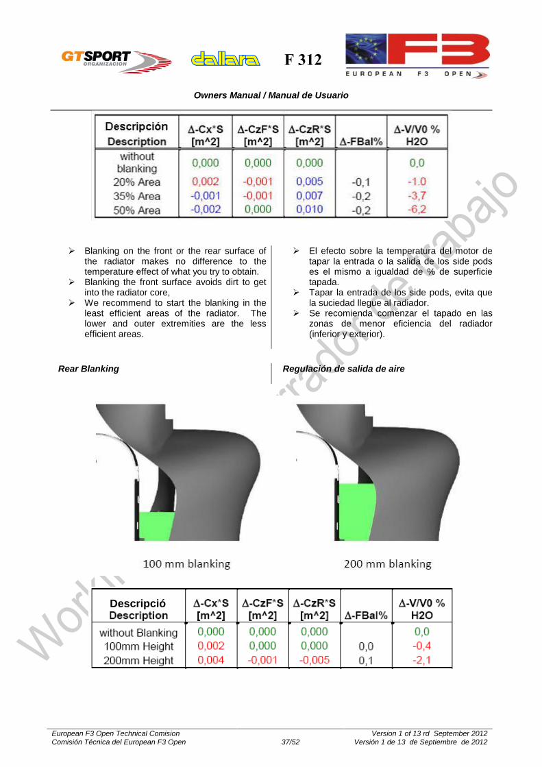
Blanking on the front or the rear surface of the radiator makes no difference to the temperature effect of what you try to obtain.
Blanking the front surface avoids dirt to get into the radiator core,
We recommend to start the blanking in the least efficient areas of the radiator. The lower and outer extremities are the less efficient areas.
El efecto sobre la temperatura del motor de tapar la entrada o la salida de los side pods es el mismo a igualdad de % de superficie tapada.
Tapar la entrada de los side pods, evita que la suciedad llegue al radiador.
Se recomienda comenzar el tapado en las zonas de menor eficiencia del radiador (inferior y exterior).
Rear Blanking
Regulación de salida de aire
Descripció
n

F 312
Owners Manual / Manual de Usuario
European F3 Open Technical Comision Comisión Técnica del European F3 Open 38/52
Version 1 of 13 rd September 2012 Versión 1 de 13 de Septiembre de 2012
FRONT AND REAR UPRIGHT
MANGUETAS DELANTERA Y TRASERA
On the front upright, both the Ackermann arm and lower wishbone bracket are supposed to be fitted directly to the upright with no spacers.
The uprights are homologated parts and cannot be modified. The homologation includes the studs for the Ackermann arm and the lower wishbone bracket. Obviously also the hub is homologated.
En La mangueta delantera, tanto el brazo Ackermann como el soporte de montaje del triángulo inferior se han de montar directamente sobre la mangueta, sin ningún tipo de separador.
Las manguetas son piezas homologadas y NO puede modificarse ninguna de sus piezas.

F 312
Owners Manual / Manual de Usuario
European F3 Open Technical Comision Comisión Técnica del European F3 Open 39/52
Version 1 of 13 rd September 2012 Versión 1 de 13 de Septiembre de 2012
FRONT UPRIGHT
MANGUETA DELANTERA
Wheel nut safety clip
Clip de seguridad de la tuerca de fijación de las ruedas
Assembly in 3 steps:
1. Put the upright in a press, and using the jig (3) T0201067 and (2) T0201068 place the bearings into the upright. Finally put the seeger.
2. Put the hub into jig (8) G31001140 with N.3 screw (7) G31001142, and by pressing on the jig (4) G31001267 and (5) G31001266 (6) G31001265 introduce the hub into the upright.
3. Tighten the bearing locking nut to 800Nm by using hexagonal key measure 65.
Montaje en 3 etapas: 1. Poner la mangueta en la prensa con el útil (3)
T0201067 y (2) T0201068, montar el rodamiento. Montar el anillo seeger.
2. Poner el buje en el útil (8) G31001140 con el tornillo N.3 (7) G31001142, y presionando el útil (4) G31001267 y (5) G31001266 (6) G31001265, introducir el buje en la mangueta
3. Apretar la tuerca de fijación a 800Nm mediante la tuerca hexagonal de 65.
INCORRECT / INCORRECTO CORRECT / CORRECTO

F 312
Owners Manual / Manual de Usuario
European F3 Open Technical Comision Comisión Técnica del European F3 Open 40/52
Version 1 of 13 rd September 2012 Versión 1 de 13 de Septiembre de 2012
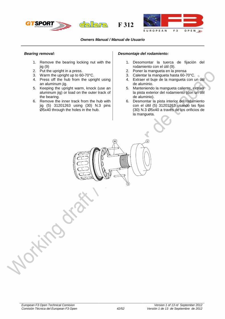
Bearing removal:
1. Remove the bearing locking nut and seeger. 2. Put the upright in a press. 3. Warm the upright up to 60-70°C. 4. Press off the hub from the upright using an
aluminum jig. 5. Keeping the upright warm, knock (use an
aluminum jig) or load on the outer track of the bearing.
6. Remove the inner track from the hub with jig (6) 31201329 using (31) N.3 pins Ø5x55 through the holes in the hub.
Desmontaje del rodamiento: 1. Desomontar la tuerca de fijación del
rodamiento y el anillo seeger. 2. Poner la mangueta en la prensa 3. Calentar la mangueta hasta 60-70°C. 4. Extraer el buje de la mangueta con un útil de
aluminio. 5. Manteniendo la mangueta caliente, extraer la
pista exterior del rodamiento (con un útil de aluminio).
6. Desmontar la pista interior del rodamiento con el últi (6) 31201329 usando las fijas (31) N.3 Ø5x55 a través de los orificios de la mangueta.

F 312
Owners Manual / Manual de Usuario
European F3 Open Technical Comision Comisión Técnica del European F3 Open 41/52
Version 1 of 13 rd September 2012 Versión 1 de 13 de Septiembre de 2012
REAR UPRIGHT
MANGUETA TRASERA
Assembly in 3 steps: 1. Put the upright in a press, and using the jig (2)
20801054, (4) T0201061 and (3) T0201062 place the bearings into the upright.
2. Put the hub into jig (7) G31001140 with N.3 screw (8) G31001142, and by pressing on the jig (5) T0201063 and (6) T0201065 introduce the hub into the upright.
3. Tighten the bearing locking nut to 500Nm by using jig (9) 31201330.
Montaje en 3 etapas:
1. Poner la mangueta en la prensa con el útil (2) 20801054, (4) T0201061 y (3) T0201062, y montar el rodamiento.
2. Poner el buje en el útil (7) G31001140 con el tornillo N.3 (8) G31001142, y presionando el útil (5) T0201063 y (6) T0201065, introducir el buje en la mangueta
3. Apretar la tuerca de fijación a 500Nm usando el útil (9) 31201330.
F 312
Owners Manual / Manual de Usuario
European F3 Open Technical Comision Comisión Técnica del European F3 Open 42/52
Version 1 of 13 rd September 2012 Versión 1 de 13 de Septiembre de 2012
Bearing removal:
1. Remove the bearing locking nut with the jig (9)
2. Put the upright in a press. 3. Warm the upright up to 60-70°C. 4. Press off the hub from the upright using
an aluminum jig. 5. Keeping the upright warm, knock (use an
aluminum jig) or load on the outer track of the bearing.
6. Remove the inner track from the hub with jig (5) 31201263 using (30) N.3 pins Ø5x40 through the holes in the hub.
Desmontaje del rodamiento:
1. Desomontar la tuerca de fijación del rodamiento con el útil (9).
2. Poner la mangueta en la prensa 3. Calentar la mangueta hasta 60-70°C. 4. Extraer el buje de la mangueta con un útil
de aluminio. 5. Manteniendo la mangueta caliente, extraer
la pista exterior del rodamiento (con un útil de aluminio).
6. Desmontar la pista interior del rodamiento con el últil (5) 31201263 usando las fijas (30) N.3 Ø5x40 a través de los orificios de la mangueta.

F 312
Owners Manual / Manual de Usuario
European F3 Open Technical Comision Comisión Técnica del European F3 Open 43/52
Version 1 of 13 rd September 2012 Versión 1 de 13 de Septiembre de 2012
OTHERS
OTROS
Engine oil level In the gear box casing, in front of the
differential housing we positioned the engine oil tank.
Typical, which means safe, level of engine oil while the engine is running can be measured as shown in this drawing:
Open the top cap and check if the oil level reaches -130 mm
At this level the tank contains 5.0 l of oil
Nivel de aceite de motor. El depósito de aceite de motor está en la
carcasa de la caja de cambios, delante del alojamiento del diferencial.
El nivel de aceite, con el motor en marcha, se puede medir como se muestra en la figura.
La medida a comprobar es -130 mm. Con esta medida, la cantidad total de aceite
es de 5.0 litros.
engine oil / Aceite de motor

F 312
Owners Manual / Manual de Usuario
European F3 Open Technical Comision Comisión Técnica del European F3 Open 44/52
Version 1 of 13 rd September 2012 Versión 1 de 13 de Septiembre de 2012
DEJAR EL QUE LLEVA EL COCHE
Fuel tank system The fuel cell contains a maximum of
approximately 45.5 litres, including the collector filled
Depósito de gasolina El depósito de gasolina contiene un máximo
de, aproximadamente, 45,5 litros, incluyendo el dep
F 312
Owners Manual / Manual de Usuario
European F3 Open Technical Comision Comisión Técnica del European F3 Open 45/52
Version 1 of 13 rd September 2012 Versión 1 de 13 de Septiembre de 2012
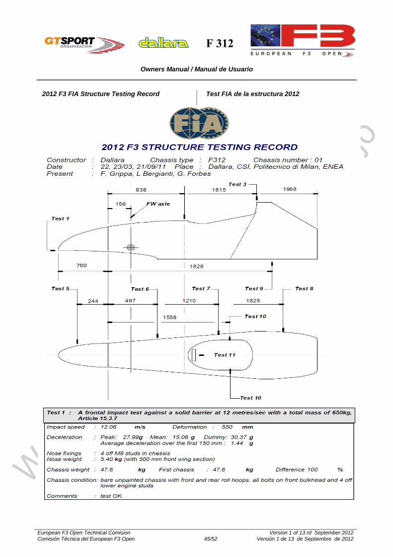
2012 F3 FIA Structure Testing Record
Test FIA de la estructura 2012

F 312
Owners Manual / Manual de Usuario
European F3 Open Technical Comision Comisión Técnica del European F3 Open 46/52
Version 1 of 13 rd September 2012 Versión 1 de 13 de Septiembre de 2012

F 312
Owners Manual / Manual de Usuario
European F3 Open Technical Comision Comisión Técnica del European F3 Open 47/52
Version 1 of 13 rd September 2012 Versión 1 de 13 de Septiembre de 2012

F 312
Owners Manual / Manual de Usuario
European F3 Open Technical Comision Comisión Técnica del European F3 Open 48/52
Version 1 of 13 rd September 2012 Versión 1 de 13 de Septiembre de 2012
Mileage of parts
In order to stay on the safe side certain parts on your car(s) will need replacement after a maximum mileage, listed here below. This list does not give typical neither minimum life of components because the here listed parts may be subjected directly or indirectly to crash damage or other life shortening influences. The list does give a mileage at which it is safe to change the part before fatigue may cause damage. We firmly request to regularly crack test all these and other components.
20.000 km: o Suspension arms o Steering rack o Steering column o Brake pedal o Uprights o Ackermann arms o Wheels
10.000 km o Brake disc bell o Wheel bearings o Wing supports
5.000km: o Drive shafts o Drive shaft tripods
Duración de las piezas Para mantener el necesario nivel de seguridad, a continuación se listan una serie de piezas del vehículo que necesitan ser sustituidas después de un determinado kilometraje. Esta lista no pretende dar ni la vida mínima ni la vida típica de los componentes, ya que su duración real está influenciada por multitud de factores (accidentes, mantenimiento, etc.). La lista proporciona el kilometraje al que es seguro sustituir la pieza antes de su fallo por fatiga. Se recomienda encarecidamente revisar regularmente las piezas en busca de posibles grietas.
20.000 km: o Triángulos de suspensión o Cremallera de dirección o Columna de dirección o Pedal de freno o Manguetas o Brazos de ackermann o Llantas
10.000 km o Núcleos de discos de freno o Rodamientos de rueda o Soportes de ala
5.000km: o Transmisiones o Juntas tripoides

F 312
Owners Manual / Manual de Usuario
European F3 Open Technical Comision Comisión Técnica del European F3 Open 49/52
Version 1 of 13 rd September 2012 Versión 1 de 13 de Septiembre de 2012
Mirrors
It is authorized to change –or supplement- the original mirror fixation arm to the chasis (L shape) for another of the same shape and material, and increased height until a maximum of 8 cm compared to the original part. If the part is supplemented, the extension will be made with an aluminium threathed extension. See attached picture.
Retrovisores Se autoriza a sustituir -o suplementar- el brazo original de sujeción (en forma de de L) del espejo retrovisor al chasis por otro de la misma forma y material, aunque de cotas superiores, de hasta un máximo de 8 cms. en su extremo mas exterior (junto al espejo). En el caso de suplementarse, la prolongacion se hará con un suplemento roscado de aluminio de la misma sección: ver foto-ejemplo.
Starter
The only authorized starters are the following ones:
DENSO Ref.: Nippon Denso 22800-1960 Ref. Toyota 28100-46140 Ref. Toyota 28100-15040/90 Ref. Toyota 18140-15090
DENSO Ref.: Nippon Denso 028000-9340 Ref. Toyota 2100-15080 (Fitted to chasis F300) Motor arranque F30827H012 Ref. Dallara 31037003 Soporte F30827H013 Ref.Dallara 30337002 Transmision shaft F30827H014 Ref.Dallara 30337006
Motor de arranque Los únicos motores de arranque autorizados son los siguientes:
DENSO Ref.: Nippon Denso 22800-1960 Ref. Toyota 28100-46140 Ref. Toyota 28100-15040/90 Ref. Toyota 18140-15090
DENSO Ref.: Nippon Denso 028000-9340 Ref. Toyota 2100-15080 (Montado en el chasis F300) Motor arranque F30827H012 Ref. Dallara 31037003 Soporte F30827H013 Ref.Dallara 30337002 Trasmision/reenvio F30827H014 Ref.Dallara 30337006

F 312
Owners Manual / Manual de Usuario
European F3 Open Technical Comision Comisión Técnica del European F3 Open 50/52
Version 1 of 13 rd September 2012 Versión 1 de 13 de Septiembre de 2012
1ª 12/35
15/34
15/31
15/32
15/30
15/29
16/30
16/30
15/27
15/26
15/25
16/26
16/25
16/24
17/25
16/23
18/25
17/23
19/25
18/23
20/25
18/22
21/25
19/22
24/27
19/21
24/26
18/19
Final Drive / Grupo cónico final para F312 - FTRL 221-12:34
2ª
STANDARD, 3ª / 4ª / 5ª / 6ª
Transmission ratios
The only authorized ratios for the kinematic chain are the following ones:
Relaciones de transmisión Las únicas relaciones autorizadas para la cadena cinemática son la siguientes:

F 312
Owners Manual / Manual de Usuario
European F3 Open Technical Comision Comisión Técnica del European F3 Open 51/52
Version 1 of 13 rd September 2012 Versión 1 de 13 de Septiembre de 2012
Brake pads
The only authorized brake pads for the F-312 are the FERODO FRP 3103C, with the usual identification marks of the Championship.
Pastilas de freno Las únicas pastillas autorizadas para el F-312 son las FERODO FRP 3103C, con las marcas identificativas del Campeonato.
Brake master cilinders
Besides the original master cylinder (Brembo ref. XA6.S2.13 – 19mm), the following ones are also autorized:
Brembo ref. XA6.S2.12 – 17,46 mm
Brembo ref. XA6.S2.14 – 20,64 mm
Bombas de freno Además de la bomba de freno original (Brembo ref. XA6.S2.13 – 19mm), se autorizan las siguientes:
Brembo ref. XA6.S2.12 – 17,46 mm
Brembo ref. XA6.S2.14 – 20,64 mm
Clutch
The only clutch that is authorized for the European F3 Open is the AP bi-disc, with the following parts references:
Clutch mechanism: CP6002: EUOF3
Intermediate discs: CP4124-102
Pressure plate: CP4124-103
Clutch discs: CP341418FM3:EUOF3
Embrague El único conjunto de embrague autorizado en el European F3 Open es el AP bidisco, con las siguientes referencias:
Mecanismo de embrague: CP6002: EUOF3
Discos intermedios: CP4124-102
Plato de presión: CP4124-103
Discos de embrague: CP341418FM3:EUOF3

F 312
Owners Manual / Manual de Usuario
European F3 Open Technical Comision Comisión Técnica del European F3 Open 52/52
Version 1 of 13 rd September 2012 Versión 1 de 13 de Septiembre de 2012
Entertainment modifications
In order to allow the correct maintenance and entertainment of the vehicles, the following modifications are autorized:
Make a hole at the side pod to permit the passage of the end of the exhaust line.
To cut the engine cover and/or the side pod at the airbox area, to avoid the interference with the engine components and ancilliaries (throttle linkage, etc.)
To install and additional ground point (it would have to be authorized by the Technical Delegate during the technical scrutineering).
To modify the wiring loom in such a way that the fuel pumps do not get automatically on when the main contact switch is connected.
Modificaciones para la explotación Para el correcto mantenimiento y explotación en carrera de los vehículos, se permiten las siguientes modificaciones:
Realizar un orificio en el side pod para el paso de la salida de la linea de escape.
Recortar el capot y/o side pod en la zona del airbox, para evitar la interferencia de los mismos con los elementos mecánicos del motor (sistema de acelerador, etc.)
Instalar un punto de masa adicional (será necesario que el montaje sea autorizado por el Delegado Técnico en las verificaciones previas.
Modificar la instalación eléctrica para que las bombas de gasolina no se accionen automáticamente al poner el contacto.