fa solaris rps3 0081610044 01 0210 gb · 1 x safety fa rotex solaris rps3 - 02/2010 5 1safety1.1...
TRANSCRIPT
For certified companies
ROTEX Solaris Solar systemControl and pump unit RPS3Operating and installation manual
Valid for the following components
ROTEX Solaris RPS3 Version 3.0 and higher
Solaris R3 temperature difference controller
Sanicube Solaris and HybridCube cylinders
Serial number
Customer
GBIssue 02/2010
SOLARIS R3P2
P1
TV
TS
TR
TK
-+
ok
007.16 011 49
Herstell-Nr.:A#:
Elektroheizstab6 kW
V = 500 l24 l93 kg593 kg
korrosionsbest‰ndig1,4 kWhT
= 85 ∞C
m ax
WarmwasserspeicherSanicubeSolaris INOX
Typ: SCS 538/16/16
Speichervolumen:
Trinkwasser-Nenninhalt:
Leergewicht:
Gesamtgewicht:
Korrosionsschutz:
Bereitschaftsw‰rmeaufwand
in 24 Stunden bei 60 ∞C
max. zul‰ssige
Speichertemperatur: max. zul‰ssiger Betriebsdruck im
-Edelstahl-W‰rmetauscher:
Dauerleistung (DIN 4708):
Leistungskennzahl (DIN 4708):
(aber maximal Ladeleistung)
Speicher 65 ∞C, Kaltwasser 10 ∞C,
Warmwasser 45 ∞C, Ladeleistung 45 kW
-Zwischenmedium:
p = 10 bar
maxdrucklos
QN = 45 kWN = 2,8
L
454297
454297XXXXXXXXX
164517-000
SanicubeSolaris
2 FA ROTEX Solaris RPS3 - 02/2010
Guarantee and conformity
Guarantee conditions
ROTEX accepts the guarantee for material and manufacturing defects according to this statement. Within the warranty period, ROTEXundertakes to have damaged parts of the installation repaired free of charge by a person assigned by the company.
ROTEX reserves the right to provide substitute replacement parts.
The warranty is only valid if the installation is used properly and if it can be proved that it was installed correctly by a specialist company. As proof, we strongly recommend completing the enclosed installation and instruction forms and returning them to ROTEX.
Warranty period
The guarantee period begins on the day of installation (billing date of the installation company), but at the latest 6 months after the date of manufacture (billing date). The warranty period is not extended if parts of the installation are returned for repairs or if components are replaced.
• Warranty period for the controller: 3 years.• Warranty for all other parts of the installation according to construction contract procedures.
Exclusion of warranty
Improper use, tampering with system components pre-assembled by ROTEXand improper modifications will immediately inval-idate the guarantee.
Dispatch and transport damage are excluded from the warranty.
The guarantee explicitly excludes follow-up costs, especially the assembly and disassembly costs of system components.
All ongoing costs, in particular claims for damages, are excluded.
There is no guarantee claim for wear parts (according to the ROTEX definition), such as lights, switches, fuses.
The warranty claim is automatically void if the connecting pipes are not run with continuous gradients and the lower edges of the collectors are not installed with a constant slope (at least 2 %) towards the return connection in the case of opposite side connections or installed horizontally in the case of same-side connections.
Declaration of conformity
for the Solaris Control and pump unit RPS3.
We, ROTEX Heating Systems GmbH, declare under our sole responsibility that the product
Product Order No.
ROTEX RPS3 16 41 06-49
complies, in its standard design, with the following European Directives:
2004/108/EC Electromagnetic Compatibility Directive
2006/95/EC Low Voltage Directive
Güglingen, 11.01.2010 Dr.-Ing. Franz GrammlingManaging Director

List of contents
3FA ROTEX Solaris RPS3 - 02/2010
1 Safety . . . . . . . . . . . . . . . . . . . . . . . . . . . . . . . . . . . . . . . . . . . . . . . . . . . . . . . . . . . . . . . . . . . . . . . . . . . . . . . . . . . 51.1 Refer to the manual. . . . . . . . . . . . . . . . . . . . . . . . . . . . . . . . . . . . . . . . . . . . . . . . . . . . . . . . . . . . . . . . . . . . . . . . . . . . . . . . . . . . . . 51.2 Warning signs and explanation of symbols . . . . . . . . . . . . . . . . . . . . . . . . . . . . . . . . . . . . . . . . . . . . . . . . . . . . . . . . . . . . . . . . . . . . . 51.3 Avoiding danger. . . . . . . . . . . . . . . . . . . . . . . . . . . . . . . . . . . . . . . . . . . . . . . . . . . . . . . . . . . . . . . . . . . . . . . . . . . . . . . . . . . . . . . . . 61.4 Intended use . . . . . . . . . . . . . . . . . . . . . . . . . . . . . . . . . . . . . . . . . . . . . . . . . . . . . . . . . . . . . . . . . . . . . . . . . . . . . . . . . . . . . . . . . . . 61.5 Instructions for working safely . . . . . . . . . . . . . . . . . . . . . . . . . . . . . . . . . . . . . . . . . . . . . . . . . . . . . . . . . . . . . . . . . . . . . . . . . . . . . 6
2 Product description. . . . . . . . . . . . . . . . . . . . . . . . . . . . . . . . . . . . . . . . . . . . . . . . . . . . . . . . . . . . . . . . . . . . . . . . . 72.1 Design and components of the Solaris system . . . . . . . . . . . . . . . . . . . . . . . . . . . . . . . . . . . . . . . . . . . . . . . . . . . . . . . . . . . . . . . . . . 72.2 Brief description . . . . . . . . . . . . . . . . . . . . . . . . . . . . . . . . . . . . . . . . . . . . . . . . . . . . . . . . . . . . . . . . . . . . . . . . . . . . . . . . . . . . . . . . 82.3 System components . . . . . . . . . . . . . . . . . . . . . . . . . . . . . . . . . . . . . . . . . . . . . . . . . . . . . . . . . . . . . . . . . . . . . . . . . . . . . . . . . . . . . 9
2.3.1 RPS3 control and pump unit . . . . . . . . . . . . . . . . . . . . . . . . . . . . . . . . . . . . . . . . . . . . . . . . . . . . . . . . . . . . . . . . . . . . . . . . . . . . 92.3.2 Flow rate meter and regulating valve. . . . . . . . . . . . . . . . . . . . . . . . . . . . . . . . . . . . . . . . . . . . . . . . . . . . . . . . . . . . . . . . . . . . . . 92.3.3 Connecting pipes and extension kits . . . . . . . . . . . . . . . . . . . . . . . . . . . . . . . . . . . . . . . . . . . . . . . . . . . . . . . . . . . . . . . . . . . . . 10
3 Installation . . . . . . . . . . . . . . . . . . . . . . . . . . . . . . . . . . . . . . . . . . . . . . . . . . . . . . . . . . . . . . . . . . . . . . . . . . . . . . 123.1 System concepts. . . . . . . . . . . . . . . . . . . . . . . . . . . . . . . . . . . . . . . . . . . . . . . . . . . . . . . . . . . . . . . . . . . . . . . . . . . . . . . . . . . . . . . 12
3.1.1 Parallel connection . . . . . . . . . . . . . . . . . . . . . . . . . . . . . . . . . . . . . . . . . . . . . . . . . . . . . . . . . . . . . . . . . . . . . . . . . . . . . . . . . . 123.1.2 Series connection . . . . . . . . . . . . . . . . . . . . . . . . . . . . . . . . . . . . . . . . . . . . . . . . . . . . . . . . . . . . . . . . . . . . . . . . . . . . . . . . . . . 12
3.2 Installing the control and pump unit . . . . . . . . . . . . . . . . . . . . . . . . . . . . . . . . . . . . . . . . . . . . . . . . . . . . . . . . . . . . . . . . . . . . . . . . . 133.2.1 Installation of pump unit . . . . . . . . . . . . . . . . . . . . . . . . . . . . . . . . . . . . . . . . . . . . . . . . . . . . . . . . . . . . . . . . . . . . . . . . . . . . . . 143.2.2 Installation of FlowSensor, FlowGuard (optional). . . . . . . . . . . . . . . . . . . . . . . . . . . . . . . . . . . . . . . . . . . . . . . . . . . . . . . . . . . . 163.2.3 Installing the cylinder temperature sensor . . . . . . . . . . . . . . . . . . . . . . . . . . . . . . . . . . . . . . . . . . . . . . . . . . . . . . . . . . . . . . . . . 173.2.4 Preparing and mounting the controller . . . . . . . . . . . . . . . . . . . . . . . . . . . . . . . . . . . . . . . . . . . . . . . . . . . . . . . . . . . . . . . . . . . . 183.2.5 Attaching the cover . . . . . . . . . . . . . . . . . . . . . . . . . . . . . . . . . . . . . . . . . . . . . . . . . . . . . . . . . . . . . . . . . . . . . . . . . . . . . . . . . 19
3.3 Connecting several DHW cylinders together. . . . . . . . . . . . . . . . . . . . . . . . . . . . . . . . . . . . . . . . . . . . . . . . . . . . . . . . . . . . . . . . . . . 193.3.1 Installation of the cylinder extension kit for 2 DHW cylinders . . . . . . . . . . . . . . . . . . . . . . . . . . . . . . . . . . . . . . . . . . . . . . . . . . 20
4 Commissioning and decommissioning . . . . . . . . . . . . . . . . . . . . . . . . . . . . . . . . . . . . . . . . . . . . . . . . . . . . . . . . . 224.1 Commissioning . . . . . . . . . . . . . . . . . . . . . . . . . . . . . . . . . . . . . . . . . . . . . . . . . . . . . . . . . . . . . . . . . . . . . . . . . . . . . . . . . . . . . . . . 22
4.1.1 Installations with FlowSensor . . . . . . . . . . . . . . . . . . . . . . . . . . . . . . . . . . . . . . . . . . . . . . . . . . . . . . . . . . . . . . . . . . . . . . . . . . 224.1.2 Installations without FlowSensor . . . . . . . . . . . . . . . . . . . . . . . . . . . . . . . . . . . . . . . . . . . . . . . . . . . . . . . . . . . . . . . . . . . . . . . 23
4.2 Decommissioning. . . . . . . . . . . . . . . . . . . . . . . . . . . . . . . . . . . . . . . . . . . . . . . . . . . . . . . . . . . . . . . . . . . . . . . . . . . . . . . . . . . . . . . 254.2.1 Temporary shutdown . . . . . . . . . . . . . . . . . . . . . . . . . . . . . . . . . . . . . . . . . . . . . . . . . . . . . . . . . . . . . . . . . . . . . . . . . . . . . . . . 254.2.2 Permanent decommissioning . . . . . . . . . . . . . . . . . . . . . . . . . . . . . . . . . . . . . . . . . . . . . . . . . . . . . . . . . . . . . . . . . . . . . . . . . . . 25

List of contents
4 FA ROTEX Solaris RPS3 - 02/2010
5 Control unit . . . . . . . . . . . . . . . . . . . . . . . . . . . . . . . . . . . . . . . . . . . . . . . . . . . . . . . . . . . . . . . . . . . . . . . . . . . . . . 275.1 Operating and display elements . . . . . . . . . . . . . . . . . . . . . . . . . . . . . . . . . . . . . . . . . . . . . . . . . . . . . . . . . . . . . . . . . . . . . . . . . . . . 275.2 Controller operating principle . . . . . . . . . . . . . . . . . . . . . . . . . . . . . . . . . . . . . . . . . . . . . . . . . . . . . . . . . . . . . . . . . . . . . . . . . . . . . . 27
5.2.1 Pump operation . . . . . . . . . . . . . . . . . . . . . . . . . . . . . . . . . . . . . . . . . . . . . . . . . . . . . . . . . . . . . . . . . . . . . . . . . . . . . . . . . . . . . 285.2.2 Booster function for high collector temperatures . . . . . . . . . . . . . . . . . . . . . . . . . . . . . . . . . . . . . . . . . . . . . . . . . . . . . . . . . . . . 285.2.3 Switch-on inhibit functions . . . . . . . . . . . . . . . . . . . . . . . . . . . . . . . . . . . . . . . . . . . . . . . . . . . . . . . . . . . . . . . . . . . . . . . . . . . . 285.2.4 Pump kick function . . . . . . . . . . . . . . . . . . . . . . . . . . . . . . . . . . . . . . . . . . . . . . . . . . . . . . . . . . . . . . . . . . . . . . . . . . . . . . . . . . 295.2.5 Manual operation . . . . . . . . . . . . . . . . . . . . . . . . . . . . . . . . . . . . . . . . . . . . . . . . . . . . . . . . . . . . . . . . . . . . . . . . . . . . . . . . . . . . 295.2.6 Solaris FlowSensor . . . . . . . . . . . . . . . . . . . . . . . . . . . . . . . . . . . . . . . . . . . . . . . . . . . . . . . . . . . . . . . . . . . . . . . . . . . . . . . . . . 295.2.7 Output calculation, maximum values, and yield count . . . . . . . . . . . . . . . . . . . . . . . . . . . . . . . . . . . . . . . . . . . . . . . . . . . . . . . . . 305.2.8 Speed control of the circulation pump P1 . . . . . . . . . . . . . . . . . . . . . . . . . . . . . . . . . . . . . . . . . . . . . . . . . . . . . . . . . . . . . . . . . . 305.2.9 Overall reset function . . . . . . . . . . . . . . . . . . . . . . . . . . . . . . . . . . . . . . . . . . . . . . . . . . . . . . . . . . . . . . . . . . . . . . . . . . . . . . . . 325.2.10 Frost protection function . . . . . . . . . . . . . . . . . . . . . . . . . . . . . . . . . . . . . . . . . . . . . . . . . . . . . . . . . . . . . . . . . . . . . . . . . . . . . . 325.2.11 Plant leakage protection function. . . . . . . . . . . . . . . . . . . . . . . . . . . . . . . . . . . . . . . . . . . . . . . . . . . . . . . . . . . . . . . . . . . . . . . . 32
5.3 Adjustments and menu guidance. . . . . . . . . . . . . . . . . . . . . . . . . . . . . . . . . . . . . . . . . . . . . . . . . . . . . . . . . . . . . . . . . . . . . . . . . . . . 335.3.1 Display during start-up. . . . . . . . . . . . . . . . . . . . . . . . . . . . . . . . . . . . . . . . . . . . . . . . . . . . . . . . . . . . . . . . . . . . . . . . . . . . . . . . 335.3.2 Display during operation. . . . . . . . . . . . . . . . . . . . . . . . . . . . . . . . . . . . . . . . . . . . . . . . . . . . . . . . . . . . . . . . . . . . . . . . . . . . . . . 345.3.3 Setup menu . . . . . . . . . . . . . . . . . . . . . . . . . . . . . . . . . . . . . . . . . . . . . . . . . . . . . . . . . . . . . . . . . . . . . . . . . . . . . . . . . . . . . . . . 345.3.4 Password protection . . . . . . . . . . . . . . . . . . . . . . . . . . . . . . . . . . . . . . . . . . . . . . . . . . . . . . . . . . . . . . . . . . . . . . . . . . . . . . . . . 365.3.5 Language selection . . . . . . . . . . . . . . . . . . . . . . . . . . . . . . . . . . . . . . . . . . . . . . . . . . . . . . . . . . . . . . . . . . . . . . . . . . . . . . . . . . 365.3.6 Adjusting and resetting parameters . . . . . . . . . . . . . . . . . . . . . . . . . . . . . . . . . . . . . . . . . . . . . . . . . . . . . . . . . . . . . . . . . . . . . . 365.3.7 Manual adjustment of pump speed control . . . . . . . . . . . . . . . . . . . . . . . . . . . . . . . . . . . . . . . . . . . . . . . . . . . . . . . . . . . . . . . . . 375.3.8 Correcting values for measurement points . . . . . . . . . . . . . . . . . . . . . . . . . . . . . . . . . . . . . . . . . . . . . . . . . . . . . . . . . . . . . . . . . 375.3.9 Burner inhibit contact . . . . . . . . . . . . . . . . . . . . . . . . . . . . . . . . . . . . . . . . . . . . . . . . . . . . . . . . . . . . . . . . . . . . . . . . . . . . . . . . 37
5.4 Recommended settings. . . . . . . . . . . . . . . . . . . . . . . . . . . . . . . . . . . . . . . . . . . . . . . . . . . . . . . . . . . . . . . . . . . . . . . . . . . . . . . . . . . 395.4.1 Standard parameter values, recommended adjustment ranges . . . . . . . . . . . . . . . . . . . . . . . . . . . . . . . . . . . . . . . . . . . . . . . . . . 395.4.2 Other adjustments of your Solaris system . . . . . . . . . . . . . . . . . . . . . . . . . . . . . . . . . . . . . . . . . . . . . . . . . . . . . . . . . . . . . . . . . 405.4.3 Recommended settings for auxiliary heating via external heat sources or the electric heater, burner inhibit contact . . . . . . . . . 415.4.4 Tips for optimised user behaviour. . . . . . . . . . . . . . . . . . . . . . . . . . . . . . . . . . . . . . . . . . . . . . . . . . . . . . . . . . . . . . . . . . . . . . . . 425.4.5 Domestic water hygiene. . . . . . . . . . . . . . . . . . . . . . . . . . . . . . . . . . . . . . . . . . . . . . . . . . . . . . . . . . . . . . . . . . . . . . . . . . . . . . . 42
6 Faults and malfunctions. . . . . . . . . . . . . . . . . . . . . . . . . . . . . . . . . . . . . . . . . . . . . . . . . . . . . . . . . . . . . . . . . . . . 436.1 Display of events . . . . . . . . . . . . . . . . . . . . . . . . . . . . . . . . . . . . . . . . . . . . . . . . . . . . . . . . . . . . . . . . . . . . . . . . . . . . . . . . . . . . . . . 436.2 Troubleshooting . . . . . . . . . . . . . . . . . . . . . . . . . . . . . . . . . . . . . . . . . . . . . . . . . . . . . . . . . . . . . . . . . . . . . . . . . . . . . . . . . . . . . . . . 44
7 Hydraulic system integration . . . . . . . . . . . . . . . . . . . . . . . . . . . . . . . . . . . . . . . . . . . . . . . . . . . . . . . . . . . . . . . 477.1 Schematic diagrams . . . . . . . . . . . . . . . . . . . . . . . . . . . . . . . . . . . . . . . . . . . . . . . . . . . . . . . . . . . . . . . . . . . . . . . . . . . . . . . . . . . . . 477.2 Short names. . . . . . . . . . . . . . . . . . . . . . . . . . . . . . . . . . . . . . . . . . . . . . . . . . . . . . . . . . . . . . . . . . . . . . . . . . . . . . . . . . . . . . . . . . . 507.3 Connection of a pressurised collector system . . . . . . . . . . . . . . . . . . . . . . . . . . . . . . . . . . . . . . . . . . . . . . . . . . . . . . . . . . . . . . . . . . 51
8 Technical data. . . . . . . . . . . . . . . . . . . . . . . . . . . . . . . . . . . . . . . . . . . . . . . . . . . . . . . . . . . . . . . . . . . . . . . . . . . . 528.1 Control and pump unit RPS3 . . . . . . . . . . . . . . . . . . . . . . . . . . . . . . . . . . . . . . . . . . . . . . . . . . . . . . . . . . . . . . . . . . . . . . . . . . . . 528.2 Sensor characteristics . . . . . . . . . . . . . . . . . . . . . . . . . . . . . . . . . . . . . . . . . . . . . . . . . . . . . . . . . . . . . . . . . . . . . . . . . . . . . . . . . . . 528.3 Terminal assignment of the RPS3 controller . . . . . . . . . . . . . . . . . . . . . . . . . . . . . . . . . . . . . . . . . . . . . . . . . . . . . . . . . . . . . . . . . . . 53
9 List of keywords . . . . . . . . . . . . . . . . . . . . . . . . . . . . . . . . . . . . . . . . . . . . . . . . . . . . . . . . . . . . . . . . . . . . . . . . . . 54
10 Notes . . . . . . . . . . . . . . . . . . . . . . . . . . . . . . . . . . . . . . . . . . . . . . . . . . . . . . . . . . . . . . . . . . . . . . . . . . . . . . . . . . . 55
1 x Safety
5FA ROTEX Solaris RPS3 - 02/2010
1 Safety1.1 Refer to the manual
This manual is intended for authorised and trained technicians who have experience of the proper installation and commissioning of heating systems on account of their technical training and knowledge.
All activities required for installation, commissioning, operation, and adjustment of the heating system are described in this manual. For detailed information on the equipment connected to your heating system, please refer to the corresponding manuals.
Please read this manual carefully and thoroughly before proceeding with the installation and commissioning or carrying out an operation on the heating system.
Relevant documentsThe documents listed below are part of the technical documentation for the ROTEX Solaris system and must also be observed. The documents are included in the scope of supply of the individual components.
– ROTEX Solaris V21P, V26P and H26P high output flat collectors: Installation instructions for on-roof, in-roof and flat roof mounting
– ROTEX DHW cylinders (Sanicube Solaris/HybridCube, GasSolarUnit (GSU) or HPSU compact): Operating and installation instructions
When connecting to an external heat generator or storage tank which is not included in the scope of delivery, the individual associated operating and installation instructions apply.
1.2 Warning signs and explanation of symbols
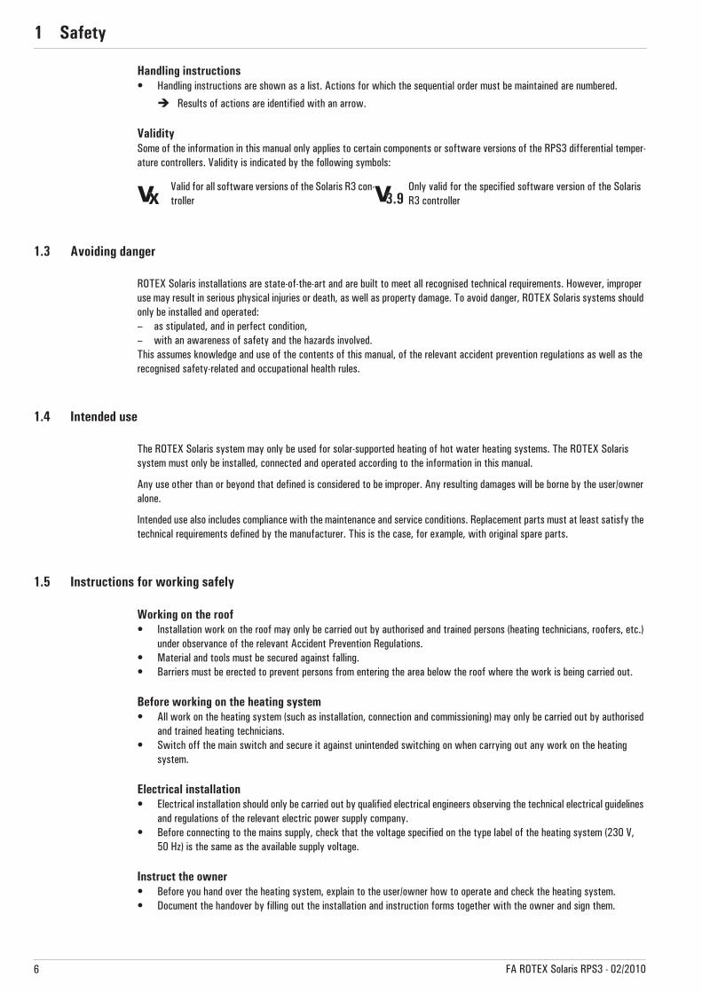
Meaning of the warningsWarnings in this manual are classified according into their severity and probability of occurrence.
Special warning symbolsSome types of danger are indicated by special warning symbols.
Order numberNotes relating to ordering numbers are identified by the cart symbol .
DANGER!
Draws attention to imminent danger.
Disregarding this warning results in serious physical injury or death.
WARNING!
Indicates a potentially dangerous situation.
Disregarding this warning may result in serious physical injury or death.
CAUTION!
Indicates a potentially damaging situation.
Disregarding this warning may cause damage to property and the environment.
This symbol identifies user tips and particularly useful information, but not warnings or hazards.
Danger of burning or scalding Electric current
1 x Safety
6 FA ROTEX Solaris RPS3 - 02/2010
Handling instructions• Handling instructions are shown as a list. Actions for which the sequential order must be maintained are numbered.
� Results of actions are identified with an arrow.
ValiditySome of the information in this manual only applies to certain components or software versions of the RPS3 differential temper-ature controllers. Validity is indicated by the following symbols:
1.3 Avoiding danger
ROTEX Solaris installations are state-of-the-art and are built to meet all recognised technical requirements. However, improper use may result in serious physical injuries or death, as well as property damage. To avoid danger, ROTEX Solaris systems should only be installed and operated:– as stipulated, and in perfect condition,– with an awareness of safety and the hazards involved.This assumes knowledge and use of the contents of this manual, of the relevant accident prevention regulations as well as the recognised safety-related and occupational health rules.
1.4 Intended use
The ROTEX Solaris system may only be used for solar-supported heating of hot water heating systems. The ROTEX Solaris system must only be installed, connected and operated according to the information in this manual.
Any use other than or beyond that defined is considered to be improper. Any resulting damages will be borne by the user/owner alone.
Intended use also includes compliance with the maintenance and service conditions. Replacement parts must at least satisfy the technical requirements defined by the manufacturer. This is the case, for example, with original spare parts.
1.5 Instructions for working safely
Working on the roof• Installation work on the roof may only be carried out by authorised and trained persons (heating technicians, roofers, etc.)
under observance of the relevant Accident Prevention Regulations.• Material and tools must be secured against falling.• Barriers must be erected to prevent persons from entering the area below the roof where the work is being carried out.
Before working on the heating system• All work on the heating system (such as installation, connection and commissioning) may only be carried out by authorised
and trained heating technicians.• Switch off the main switch and secure it against unintended switching on when carrying out any work on the heating
system.
Electrical installation• Electrical installation should only be carried out by qualified electrical engineers observing the technical electrical guidelines
and regulations of the relevant electric power supply company.• Before connecting to the mains supply, check that the voltage specified on the type label of the heating system (230 V,
50 Hz) is the same as the available supply voltage.
Instruct the owner• Before you hand over the heating system, explain to the user/owner how to operate and check the heating system.• Document the handover by filling out the installation and instruction forms together with the owner and sign them.
Valid for all software versions of the Solaris R3 con-troller
Only valid for the specified software version of the Solaris R3 controller3.93.9
2 x Product description
7FA ROTEX Solaris RPS3 - 02/2010
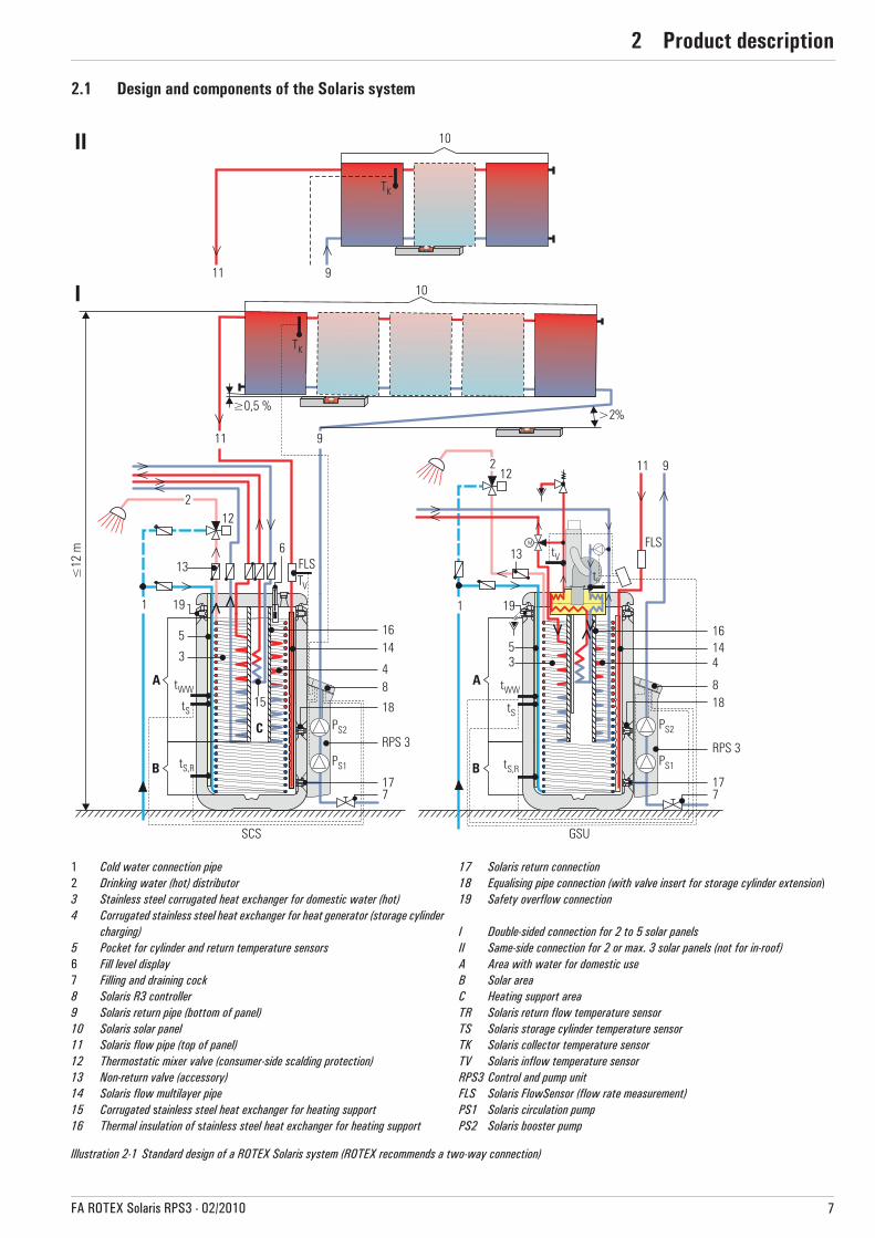
2 Product description2.1 Design and components of the Solaris system
1 Cold water connection pipe2 Drinking water (hot) distributor3 Stainless steel corrugated heat exchanger for domestic water (hot)4 Corrugated stainless steel heat exchanger for heat generator (storage cylinder
charging)5 Pocket for cylinder and return temperature sensors6 Fill level display7 Filling and draining cock8 Solaris R3 controller9 Solaris return pipe (bottom of panel)10 Solaris solar panel11 Solaris flow pipe (top of panel)12 Thermostatic mixer valve (consumer-side scalding protection)13 Non-return valve (accessory)14 Solaris flow multilayer pipe15 Corrugated stainless steel heat exchanger for heating support16 Thermal insulation of stainless steel heat exchanger for heating support
17 Solaris return connection18 Equalising pipe connection (with valve insert for storage cylinder extension)19 Safety overflow connection
I Double-sided connection for 2 to 5 solar panelsII Same-side connection for 2 or max. 3 solar panels (not for in-roof)A Area with water for domestic useB Solar areaC Heating support areaTR Solaris return flow temperature sensorTS Solaris storage cylinder temperature sensorTK Solaris collector temperature sensorTV Solaris inflow temperature sensorRPS3 Control and pump unitFLS Solaris FlowSensor (flow rate measurement) PS1 Solaris circulation pumpPS2 Solaris booster pump
Illustration 2-1 Standard design of a ROTEX Solaris system (ROTEX recommends a two-way connection)
2 x Product description
8 FA ROTEX Solaris RPS3 - 02/2010
2.2 Brief description
The ROTEX Solaris system is a thermal solar system for supplying hot water for consumption and heating support.
Mode of operationThe Solaris V21P, V26P and H26P high-performance flat solar panels convert the sun's radiation into heat with high efficiency. The heat transport medium is normal tap water.
As soon as the solar collectors have reached a useful temperature level, the water of the heating jacket in the storage cylinder (which is not under pressure) is pumped directly through the collectors. With insufficient collector temperature, the circulation pump is switched off and the system is drained automatically. This operating mode has several advantages:– High operational reliability, as there are no components that could be damaged or fail (such as expansion vessel, safety valve,
venting valves, etc.).– Excellent heat transfer and heat storage capacity (system works without antifreeze agents).– Minimum maintenance requirements.– Frost proof.– No additional solar heat exchanger.– No problems with stagnation.
Modular designThe system consists of several mainly pre-assembled modules. Plug-in technology and a high degree of pre-assembly ensure fast and simple system installation.
Storage cylinderThe following storage cylinders can be used for the ROTEX Solaris system:– ROTEX Sanicube Solaris (SCS): thermally insulated, unpressurised plastic cylinder (with the facility to connect a ROTEX con-
densing boiler).– ROTEX HybridCube (HYC): thermally insulated, unpressurised plastic cylinder (with the facility to connect a ROTEX air-water
heat pump).– ROTEX GasSolarUnit (GSU): Sanicube Solaris with integrated gas-fired condensing boiler.– ROTEX HPSU compact: HybridCube DHW cylinder with integrated indoor unit for an air-water heat pump.
Electronic controlThe ROTEX Solaris R3 fully electronic control unit ensures optimum utilization of the solar heat (hot water generation, heating support) as well as the compliance with all aspects of operating safety. All parameters needed for trouble-free operation have been preset at the factory.
The ROTEX Control and pump unit RPS3 can only be installed and operated in the unpressurised ROTEX Solaris system (drainback), using the assembly material provided.
The requirement for trouble-free operation in the drainback system is that the connecting pipes are run with a continuous slope (at least 2 %), and that the lower edges of the collectors are installed with a constant slope to the return connection when the connections are double-sided, or horizontally if the connections are on the same side.
Construction, operating principle, commissioning, and operation of the storage cylinder are not described in this manual. Detailed information on the storage cylinders is given in the manuals of the respective units.
The handling instructions and descriptions quoted in this manual basically apply to all the ROTEX storage cylin-ders that can be used with this solar installation, even if only one type (e. g., SCS) is described for purposes of illustration. Where other cylinders deviate, this will be pointed out separately.
2 x Product description
9FA ROTEX Solaris RPS3 - 02/2010
2.3 System components
2.3.1 RPS3 control and pump unit
16 41 06-49
2.3.2 Flow rate meter and regulating valve
FlowSensor FLS20
FlowGuard FLG
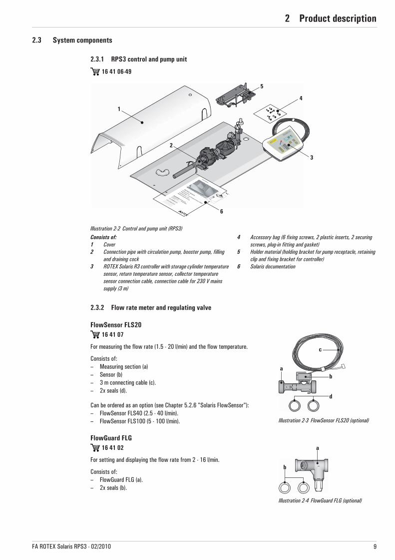
Illustration 2-2 Control and pump unit (RPS3)Consists of:1 Cover2 Connection pipe with circulation pump, booster pump, filling
and draining cock3 ROTEX Solaris R3 controller with storage cylinder temperature
sensor, return temperature sensor, collector temperature sensor connection cable, connection cable for 230 V mains supply (3 m)
4 Accessory bag (6 fixing screws, 2 plastic inserts, 2 securing screws, plug-in fitting and gasket)
5 Holder material (holding bracket for pump receptacle, retaining clip and fixing bracket for controller)
6 Solaris documentation
16 41 07
For measuring the flow rate (1.5 - 20 l/min) and the flow temperature.
Consists of:– Measuring section (a)– Sensor (b)– 3 m connecting cable (c).– 2x seals (d).
Can be ordered as an option (see Chapter 5.2.6 "Solaris FlowSensor"):– FlowSensor FLS40 (2.5 - 40 l/min).– FlowSensor FLS100 (5 - 100 l/min). Illustration 2-3 FlowSensor FLS20 (optional)
16 41 02
For setting and displaying the flow rate from 2 - 16 l/min.
Consists of:– FlowGuard FLG (a).– 2x seals (b).
Illustration 2-4 FlowGuard FLG (optional)

2 x Product description
10 FA ROTEX Solaris RPS3 - 02/2010
2.3.3 Connecting pipes and extension kits
Cylinder extension kit CON SX
Cylinder extension kit 2 CON SXE
Equalising pipe AGL
Equalising pipe extension kit AGLE
Extension kit for additional heat source EWS
16 01 07
For connecting 2 Sanicube Solaris or 2 HybridCube storage tanks.
Consists of:
– Return connecting pipe (a).– Flow distributor (b).
Illustration 2-5CON SX (optional)
16 01 11
Extension kit for connecting a second Sanicube Solaris or HybridCube storage tank.
Consists of:– Return connecting pipe (a).– Flow distributor (b).
Illustration 2-6 CON SXE (optional)
16 01 08
Equalising pipe for preventing differences in level between 2 connected storage tanks (for 2 Sanicube Solaris storage tanks, 2 HybridCube storage tanks or for 2 GSU storage tanks).
Consists of:– Equalising pipe.Used in conjunction with CON SX.
Illustration 2-7 AGL (optional)
16 01 12
Equalising pipe extension kit for preventing differences in level between 2 connected storage tanks (for 2 Sanicube Solaris storage tanks, 2 HybridCube storage tanks or for 2 GSU storage tanks).
Consists of:– Equalising pipe.Used in conjunction with CON SXE. Illustration 2-8 AGLE (optional)
16 01 10
Extension kit for connecting a second heat source in combination with a Control and pump unit RPS3 to the unpressurised storage tank.Consists of:– 1x T-piece for the return, with a 1" screw coupling (a).– 1x connecting nipple for the flow, with a 3/4" screw cou-
pling (b).Illustration 2-9 EWS (optional)

2 x Product description
11FA ROTEX Solaris RPS3 - 02/2010
Solar connection SAG for GSU 32016 42 28
Flow pipe for the solar connection to the GSU 320Consists of:– Preassembled, thermally insulated connecting pipe.
Illustration 2-10SAG (optional)

3 x Installation
12 FA ROTEX Solaris RPS3 - 02/2010
3 Installation3.1 System concepts
ROTEX Solaris installations are normally built according to one of the following system concepts. Information concerning hydraulic system integration with specimen schematic diagrams can be found in Chapter 7 "Hydraulic system integration".
3.1.1 Parallel connection
3.1.2 Series connection
As an alternative to the purely parallel collector installation described in this manual, a maximum of 3 rows of collectors can also be mounted above each other as required. With such an arrangement, the collectors or collector arrays must be connected in series (Image 3-3).
Illustration 3-1 Double-sided connection of solar collector array(recommended)
Illustration 3-2 Same-side connection of solar collector array(max. of 3 solar collectors)
1 Collector connector2 Mounting rail3 Collector securing hook4 Solar collector5 Collector return connection6 Collector flow connection7 Collector sealing cap8 Roof penetration boxes for flow/return9 Solar return pipe10 Solar flow pipe11 Collector row interconnector12 Solar collector array (2x 2 collectors)
Illustration 3-3 Alternative collector arrangement
3 x Installation
13FA ROTEX Solaris RPS3 - 02/2010
3.2 Installing the control and pump unit
WARNING!
Live parts can cause an electric shock on contact and cause life-threatening burns and injuries.• Before beginning maintenance work on the boiler control panel or the solar control system, disconnect
both units from the power supply (remove fuse, switch off main switch) and secure against unintentional switch-on.
• To prevent hazards caused by damaged electrical cables, always have them replaced by a qualified electrician in compliance with the applicable electrical guidelines and the regulations of the responsible electricity supply company.
• Comply with the relevant safety at work regulations.
DANGER!
Escaping gas in the immediate vicinity of electrical parts can cause explosions.• Do not install the Control and pump unit RPS3 or electrical components in locations where there is a risk
of escaping, inflammable gas.• Observe the minimum clearances to walls and in shafts.
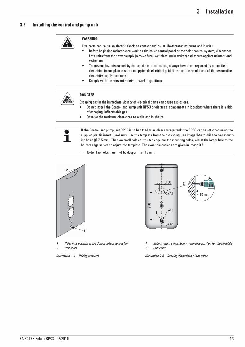
If the Control and pump unit RPS3 is to be fitted to an older storage tank, the RPS3 can be attached using the supplied plastic inserts (Well nut). Use the template from the packaging (see Image 3-4) to drill the two mount-ing holes (Ø 7.5 mm). The two small holes at the top edge are the mounting holes, whilst the larger hole at the bottom edge serves to adjust the template. The exact dimensions are given in Image 3-5.
– Note: The holes must not be deeper than 15 mm.
1 Reference position of the Solaris return connection2 Drill holes
1 Solaris return connection = reference position for the template2 Drill holes
Illustration 3-4 Drilling template Illustration 3-5 Spacing dimensions of the holes

3 x Installation
14 FA ROTEX Solaris RPS3 - 02/2010
3.2.1 Installation of pump unit
1. Remove the handle from the DHW cylinder and unscrew the sealing cap from the solar return connection.
2. Use the previously removed handle screws to attach the pump holding bracket to the upper plastic inserts of the handle mounting.
3. If the combined filling and draining cock in the cylinder connecting bracket of the preassembled pump group is to be located on the other side (Image 3-8):
• Remove both retaining clips (a).• Withdraw the blanking plug and the combined filling and draining cock.• Insert the combined filling and draining cock in the desired side and secure it with a retaining clip.• Insert the blanking plug in the opposite side to the filling and draining cock and secure with a retaining clip.
4. Insert the supplied seal in the cylinder coupling nut and screw the preassembled pump unit on the cylinder connecting bracket to the solar return connection on the DHW cylinder. Mounting is simplified, if the retainer is clipped into the holding bracket.
5. Open the bleed valve, on the upper pump, by one turn.
6. Tighten the cylinder coupling nut.
CAUTION!
Large amounts of water can escape from the DHW cylinder during installation.• Fit the pump unit before filling the DHW cylinder (unpressurised zone) with water.• If the pump unit is to be connected to a DHW cylinder which is already in operation, the unpressurised
zone of the cylinder must first be drained.
Illustration 3-6 Step 1 Illustration 3-7 Step 2 Illustration 3-8 Step 3
Illustration 3-9 Step 4 Illustration 3-10 Steps 5+6

3 x Installation
15FA ROTEX Solaris RPS3 - 02/2010
7. Screw the retainer to the holding bracket (necessary to withstand forces).
8. Screw on the fixing bracket for the controller.
9. Mount the push-in elbow fitting (Ø 22/Ø 18).
10. Prepare the flow pipe (VA 15 Solar) with the sensor cable and the return pipe (VA 18 Solar). Cut the Twin-Tube insulation apart in the middle.
11. Cut the return pipe to size (VA 18 Solar) and run it separately after splitting the Twin-Tube insulation.
12. Insert the pre-bent return flow pipe (VA 18 Solar) into the push-in fitting of the pump coupling.
13. Cut the flow pipe (VA Solar 15) on the cylinder side to the required length and insert it into the push-in fitting on the solar flow connection (see Chapter 3.3 "Connecting several DHW cylinders together", FlowSensor, Step 4).
Illustration 3-11 Step 7 Illustration 3-12 Step 8 Illustration 3-13 Step 9
Illustration 3-14 Step 10 Illustration 3-15 Step 11 Illustration 3-16 Step 12
CAUTION!
In the case of longer pipe runs with only a minimum gradient, it is possible for water pockets to develop due to thermal expansion of the plastic pipes between the mounting points with siphon action:• Either attach the pipe to a rigid supporting structure (e.g. mounting rail, pipe, etc.).• Always make sure that pipe runs have a continuous gradient of at least 2 %.
3 x Installation
16 FA ROTEX Solaris RPS3 - 02/2010
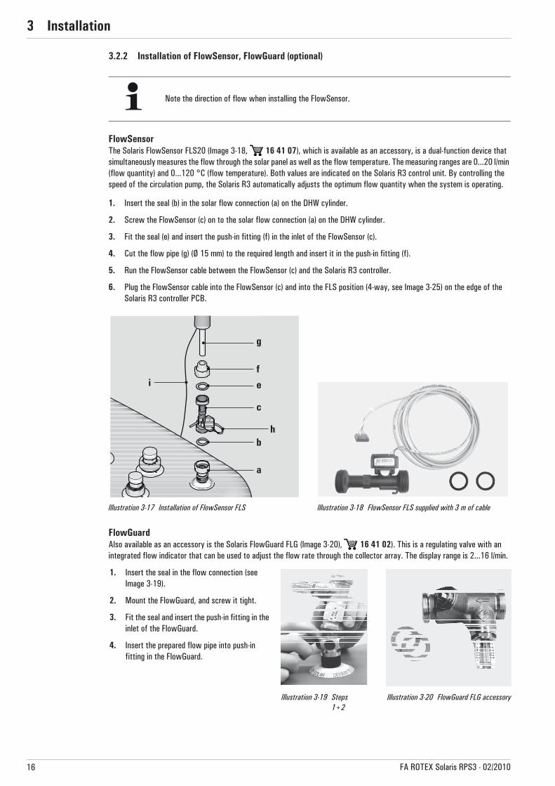
3.2.2 Installation of FlowSensor, FlowGuard (optional)
FlowSensorThe Solaris FlowSensor FLS20 (Image 3-18, 16 41 07), which is available as an accessory, is a dual-function device that simultaneously measures the flow through the solar panel as well as the flow temperature. The measuring ranges are 0...20 l/min (flow quantity) and 0...120 °C (flow temperature). Both values are indicated on the Solaris R3 control unit. By controlling the speed of the circulation pump, the Solaris R3 automatically adjusts the optimum flow quantity when the system is operating.
1. Insert the seal (b) in the solar flow connection (a) on the DHW cylinder.
2. Screw the FlowSensor (c) on to the solar flow connection (a) on the DHW cylinder.
3. Fit the seal (e) and insert the push-in fitting (f) in the inlet of the FlowSensor (c).
4. Cut the flow pipe (g) (Ø 15 mm) to the required length and insert it in the push-in fitting (f).
5. Run the FlowSensor cable between the FlowSensor (c) and the Solaris R3 controller.
6. Plug the FlowSensor cable into the FlowSensor (c) and into the FLS position (4-way, see Image 3-25) on the edge of the Solaris R3 controller PCB.
FlowGuardAlso available as an accessory is the Solaris FlowGuard FLG (Image 3-20), 16 41 02). This is a regulating valve with an integrated flow indicator that can be used to adjust the flow rate through the collector array. The display range is 2...16 l/min.
Note the direction of flow when installing the FlowSensor.
Illustration 3-17 Installation of FlowSensor FLS Illustration 3-18 FlowSensor FLS supplied with 3 m of cable
1. Insert the seal in the flow connection (see Image 3-19).
2. Mount the FlowGuard, and screw it tight.
3. Fit the seal and insert the push-in fitting in the inlet of the FlowGuard.
4. Insert the prepared flow pipe into push-in fitting in the FlowGuard.
Illustration 3-19 Steps 1+2
Illustration 3-20 FlowGuard FLG accessory
3 x Installation
17FA ROTEX Solaris RPS3 - 02/2010
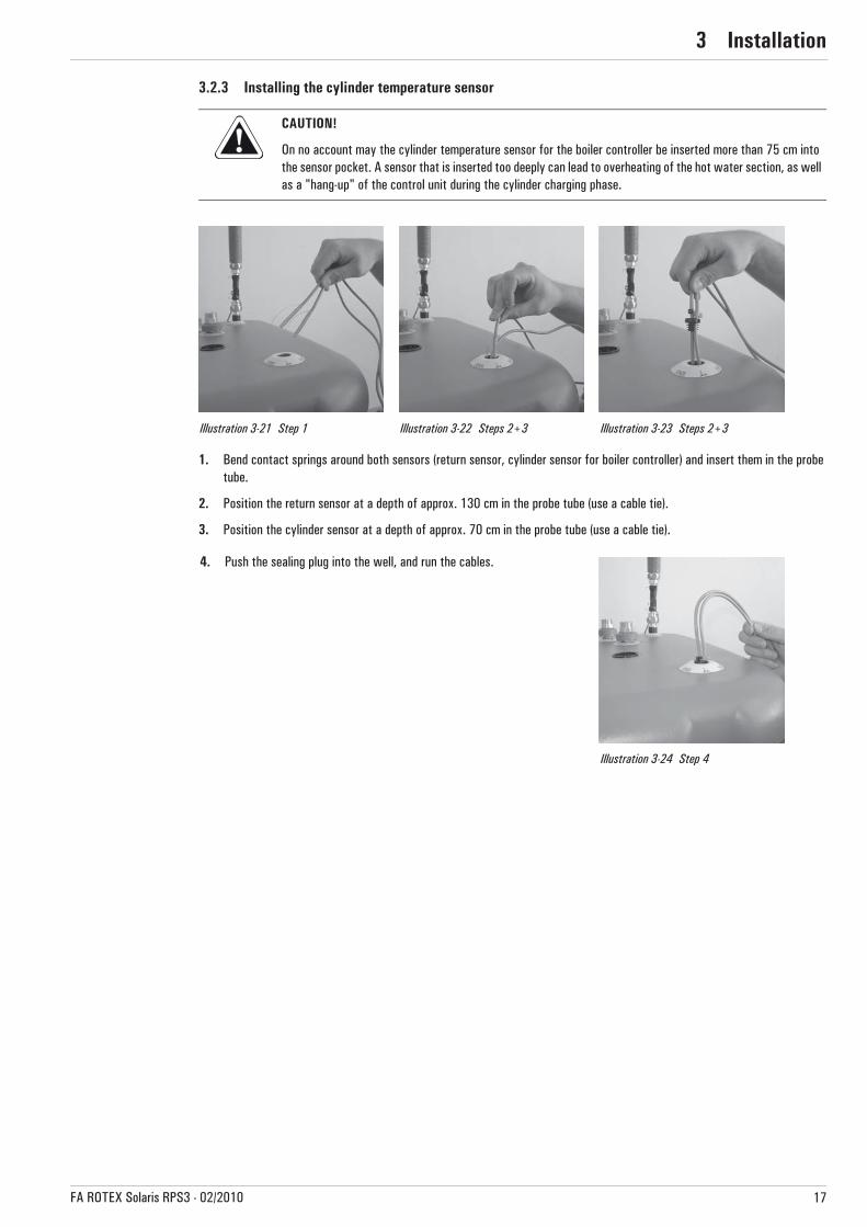
3.2.3 Installing the cylinder temperature sensor
1. Bend contact springs around both sensors (return sensor, cylinder sensor for boiler controller) and insert them in the probe tube.
2. Position the return sensor at a depth of approx. 130 cm in the probe tube (use a cable tie).
3. Position the cylinder sensor at a depth of approx. 70 cm in the probe tube (use a cable tie).
CAUTION!
On no account may the cylinder temperature sensor for the boiler controller be inserted more than 75 cm into the sensor pocket. A sensor that is inserted too deeply can lead to overheating of the hot water section, as well as a "hang-up" of the control unit during the cylinder charging phase.
Illustration 3-21 Step 1 Illustration 3-22 Steps 2+3 Illustration 3-23 Steps 2+3
4. Push the sealing plug into the well, and run the cables.
Illustration 3-24 Step 4
3 x Installation
18 FA ROTEX Solaris RPS3 - 02/2010
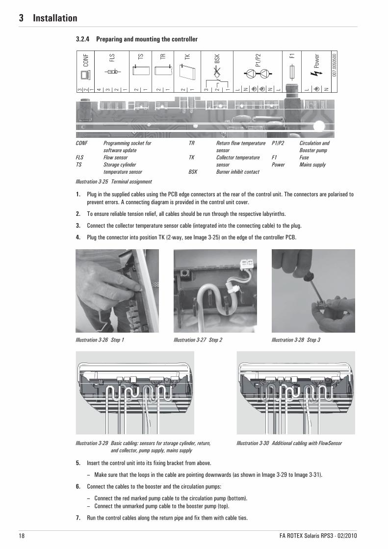
3.2.4 Preparing and mounting the controller
1. Plug in the supplied cables using the PCB edge connectors at the rear of the control unit. The connectors are polarised to prevent errors. A connecting diagram is provided in the control unit cover.
2. To ensure reliable tension relief, all cables should be run through the respective labyrinths.
3. Connect the collector temperature sensor cable (integrated into the connecting cable) to the plug.
4. Plug the connector into position TK (2-way, see Image 3-25) on the edge of the controller PCB.
5. Insert the control unit into its fixing bracket from above.
– Make sure that the loops in the cable are pointing downwards (as shown in Image 3-29 to Image 3-31).
6. Connect the cables to the booster and the circulation pumps:
– Connect the red marked pump cable to the circulation pump (bottom).– Connect the unmarked pump cable to the booster pump (top).
7. Run the control cables along the return pipe and fix them with cable ties.
CONF Programming socket for software update
FLS Flow sensorTS Storage cylinder
temperature sensor
TR Return flow temperaturesensor
TK Collector temperaturesensor
BSK Burner inhibit contact
P1/P2 Circulation and Booster pump
F1 FusePower Mains supply
Illustration 3-25 Terminal assignment
Illustration 3-26 Step 1 Illustration 3-27 Step 2 Illustration 3-28 Step 3
Illustration 3-29 Basic cabling: sensors for storage cylinder, return, and collector, pump supply, mains supply
Illustration 3-30 Additional cabling with FlowSensor
3 x Installation
19FA ROTEX Solaris RPS3 - 02/2010
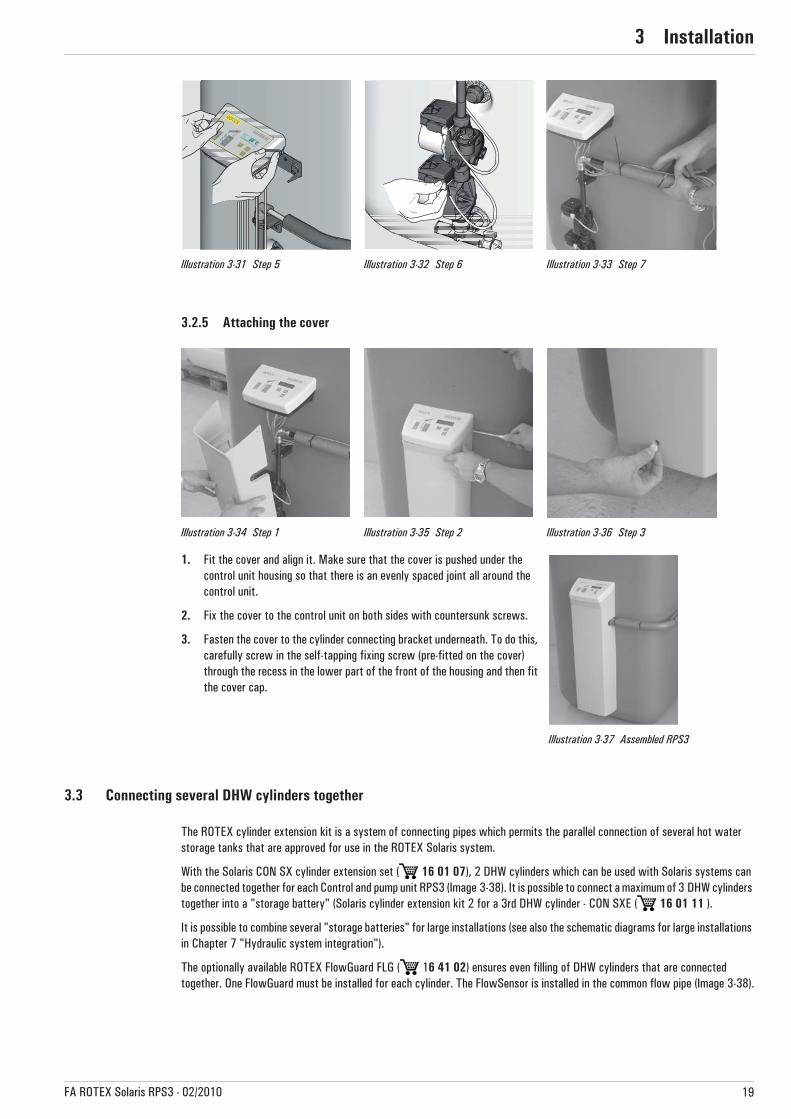
3.2.5 Attaching the cover
3.3 Connecting several DHW cylinders together
The ROTEX cylinder extension kit is a system of connecting pipes which permits the parallel connection of several hot water storage tanks that are approved for use in the ROTEX Solaris system.
With the Solaris CON SX cylinder extension set ( 16 01 07), 2 DHW cylinders which can be used with Solaris systems can be connected together for each Control and pump unit RPS3 (Image 3-38). It is possible to connect a maximum of 3 DHW cylinders together into a "storage battery" (Solaris cylinder extension kit 2 for a 3rd DHW cylinder - CON SXE ( 16 01 11 ).
It is possible to combine several "storage batteries" for large installations (see also the schematic diagrams for large installations in Chapter 7 "Hydraulic system integration").
The optionally available ROTEX FlowGuard FLG ( 16 41 02) ensures even filling of DHW cylinders that are connected together. One FlowGuard must be installed for each cylinder. The FlowSensor is installed in the common flow pipe (Image 3-38).
Illustration 3-31 Step 5 Illustration 3-32 Step 6 Illustration 3-33 Step 7
Illustration 3-34 Step 1 Illustration 3-35 Step 2 Illustration 3-36 Step 3
1. Fit the cover and align it. Make sure that the cover is pushed under the control unit housing so that there is an evenly spaced joint all around the control unit.
2. Fix the cover to the control unit on both sides with countersunk screws.
3. Fasten the cover to the cylinder connecting bracket underneath. To do this, carefully screw in the self-tapping fixing screw (pre-fitted on the cover) through the recess in the lower part of the front of the housing and then fit the cover cap.
Illustration 3-37 Assembled RPS3
3 x Installation
20 FA ROTEX Solaris RPS3 - 02/2010
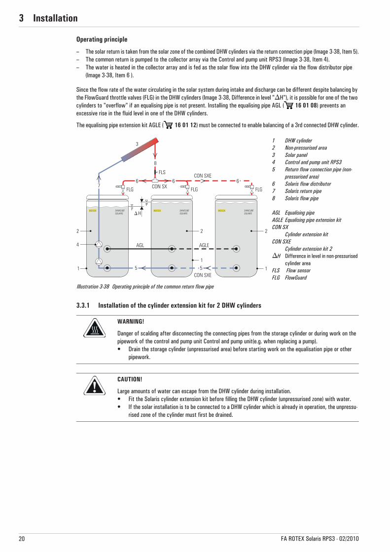
Operating principle
– The solar return is taken from the solar zone of the combined DHW cylinders via the return connection pipe (Image 3-38, Item 5).– The common return is pumped to the collector array via the Control and pump unit RPS3 (Image 3-38, Item 4).– The water is heated in the collector array and is fed as the solar flow into the DHW cylinder via the flow distributor pipe
(Image 3-38, Item 6 ).
Since the flow rate of the water circulating in the solar system during intake and discharge can be different despite balancing by the FlowGuard throttle valves (FLG) in the DHW cylinders (Image 3-38, Difference in level "�H"), it is possible for one of the two cylinders to "overflow" if an equalising pipe is not present. Installing the equalising pipe AGL ( 16 01 08) prevents an excessive rise in the fluid level in one of the DHW cylinders.
The equalising pipe extension kit AGLE ( 16 01 12) must be connected to enable balancing of a 3rd connected DHW cylinder.
3.3.1 Installation of the cylinder extension kit for 2 DHW cylinders
1 DHW cylinder2 Non-pressurised area3 Solar panel4 Control and pump unit RPS35 Return flow connection pipe (non-
pressurised area)6 Solaris flow distributor7 Solaris return pipe8 Solaris flow pipe
AGL Equalising pipeAGLE Equalising pipe extension kitCON SX
Cylinder extension kitCON SXE
Cylinder extension kit 2�H Difference in level in non-pressurised
cylinder areaFLS Flow sensorFLG FlowGuard
Illustration 3-38 Operating principle of the common return flow pipe
WARNING!
Danger of scalding after disconnecting the connecting pipes from the storage cylinder or during work on the pipework of the control and pump unit Control and pump unit(e.g. when replacing a pump).• Drain the storage cylinder (unpressurised area) before starting work on the equalisation pipe or other
pipework.
CAUTION!
Large amounts of water can escape from the DHW cylinder during installation.• Fit the Solaris cylinder extension kit before filling the DHW cylinder (unpressurised zone) with water.• If the solar installation is to be connected to a DHW cylinder which is already in operation, the unpressu-
rised zone of the cylinder must first be drained.

3 x Installation
21FA ROTEX Solaris RPS3 - 02/2010
1. Mount the RPS3 but do not fit the cover (see Chapter 3.2).
2. Unscrew the sealing cap from the Solaris return connection (see Chapter 2.1, Image 2-1, Item 17) on the 2nd cylinder.
3. Line up the Solaris DHW cylinder. The centre-to-centre distance between the storage cylinders must be 830 mm. Also observe the necessary clearance of 200 mm to any wall.
4. Prepare the cylinder connecting bracket on the Control and pump unit RPS3. Remove the retaining clip on the extension side and, depending on the previous set-up, remove the ball cock or the blanking plug (see Page 14, Step 3).
5. Fit the removed part to the return connecting pipe preassembled by ROTEX on the 2nd cylinder connecting bracket.
6. Plug the completed return pipe by the free plug-in fitting (Ø 28) into the free outlet on the cylinder connecting bracket of the Control and pump unit RPS3.
7. Fasten the return pipe to the return connection on the 2nd cylinder with the coupling nut. First insert the supplied gasket in the coupling nut.
8. Remove the lower sealing cap on the corresponding side of the cover.
9. Fit the cover to the storage tank (see Chapter 3.2.5).
10. Fit one FlowGuard (optional) to the Solaris flow connection of each storage tank (see Chapter 3.2.2).
11. Fit flow distributor pipes on the left and right of the connecting T-piece (Image 3-39, Items 3 + 4).
12. Fit gaskets in both FlowGuards and screw a flow distributor pipe to each FlowGuard using the coupling nut.
13. Fit a seal to the connecting T-piece and screw on the double union nut (1").
14. Insert the seal in the double union nut (1").
15. Fit the FlowSensor (see Chapter 3.2.2).
1 ROTEXHot water storage tank2 Control and pump unit RPS33 Solaris flow distributor4 Connecting T-piece
AGL Equalising pipeCON SX (A) Cylinder extension kit (bottom)CON SX (B) Cylinder extension kit (top)FLS FlowSensorFLG FlowGuard
Illustration 3-39 Installation of cylinder extension for 2 DHW cylinders (using 2 Sanicube Solaris as an example)

4 x Commissioning and decommissioning
22 FA ROTEX Solaris RPS3 - 02/2010
4 Commissioning and decommissioning4.1 Commissioning
All the following work must be carried out in the specified sequence.
4.1.1 Installations with FlowSensor
1. Filling the storage cylinder:
• Fill the heat exchanger for domestic water.• Fill the buffer storage volume via the filling & draining cock on the Control and pump unit RPS3 until water comes out
of the safety overflow.• Close the filling & draining cock.
2. Switch on the Solaris R3 controller.
� The initialisation phase begins.
3. When the initialising phase is finished (temperature display), fill and vent the system by simultaneously pressing both arrow keys (starts the manual operating mode).
� Both pumps are now running at full capacity, and the Solaris system is subjected to the max. possible working pressure. The Solaris system is filled with water, and the air escapes through the flow pipe into the air space of the storage cylinder.
4. Check the entire system for leaky joints (in the building and on the roof). Seal any leaks that occur in a professional manner.
5. Switch off the Solaris R3 control unit.
6. Check the fill level in the Solaris DHW cylinder.
7. Setting the filling time:
• Switch the Solaris R3 control unit on again (initialising phase starts).• When the initialising phase is finished (temperature display), you can start the manual operating mode by simultaneously
pressing both arrow keys.• Note the time it takes for the Solaris system to be filled completely. The installation is completely filled when no sound
of escaping air can be heard, and a stable flow value is indicated (use the arrow keys to select the measuring point "Flow").
• Set the determined filling time plus 20 seconds as parameter "Time P2" (see Section 5.3.6).
WARNING!
The Solaris installation may only be commissioned after all the hydraulic and electrical connections have been made.
Incorrect commissioning will impair the system's function, and can lead to damage to the entire installation. Therefore, installation and commissioning should only be carried out by heating technicians trained and authorized by ROTEX.
CAUTION!
Commissioning under frosty conditions can result in damage to the entire installation.• Commissioning with outside temperatures below 0 °C should only be undertaken if a water temperature
of at least 5 °C in the solar circuit can be guaranteed (e.g. by previous heating of the DHW cylinder).ROTEX recommends not operating the installation in extremely frosty conditions.
The fill indicator on the Solaris DHW cylinder must almost reach the filling mark again within a few minutes.
– The cause of a slightly lower fill level is the presence of a small amount of water in the lower header tubes of the collectors. If the collector array is correctly oriented, this quantity of water presents no risk to the collector, even with the effects of frost, as there is sufficient volume for expansion available.
– If the fill level remains significantly below the filling mark, this can be an indication of undiscovered leaks or an incorrect pipe run (water pockets). In this case the installation must be checked very closely once more.

4 x Commissioning and decommissioning
23FA ROTEX Solaris RPS3 - 02/2010
8. Switch the Solaris R3 control unit back to automatic operation either by simultaneously pressing both arrow keys or by switching the unit off/on.
� The Solaris system is now ready for operation.
9. The following only applies if the RPS3 Control and pump unit is connected to several Solaris DHW cylinders:
– The entire flow measured by the FlowSensor in the Solaris flow line must be distributed uniformly between all the con-nected Solaris DHW cylinders. For an even distribution, we recommend fitting a FlowGuard (FLG) to each cylinder.
10. Instruct the user, fill out the acceptance report, and send it to the address indicated on the rear cover of this manual.
4.1.2 Installations without FlowSensor
On installations without FlowSensor, a regulating valve (FlowGuard) must be fitted to the flow connection of the cylinder.
1. Filling the storage cylinder:
• Fill the heat exchanger for domestic water.• Fill the buffer storage volume via the filling & draining cock on the Control and pump unit RPS3 until water comes out
of the safety overflow.• Close the filling & draining cock.
2. Switch on the Solaris R3 controller.
� The initialisation phase begins.
3. When the initialising phase is finished (temperature display), fill and vent the Solaris system by simultaneously pressing both arrow keys (starts the manual operating mode).
� Both pumps are now running at full capacity, and the system is subjected to the max. possible working pressure. The system is filled with water, and the air escapes through the inflow pipe into the air space of the storage cylinder. A bypass in the FlowGuard regulating valve ensures that the system is vented automatically, even if the valve is fully closed.
4. Close the regulating valve completely.
� The system is now subjected to the max. possible working pressure.
5. Check the entire system for leaky joints (in the building and on the roof). Seal any leaks that occur in a professional manner.
6. Adjust the flow in accordance with the number of collectors. For reference valve settings, see Table 4-1.
7. Switch off the Solaris R3 control unit.
The correct flow rate in the solar circuit is set automatically by controlling the speed of the circulation pump.
If the total height of the installation is less than 10 m, it is possible to reduce the electrical power consumption of the circulation pump P1 by selecting a lower output on the pump speed switch. The requirement is that after the reduction in output, the system can still be filled without problems and a flow rate according to Table 4-1 is achieved. The booster pump should always be set to speed 3.
As both pumps are running during commissioning in the manual operating mode, the basic setting should be at the upper limit values.
If the total height of the installation is less than 10 m, it is possible to reduce the electrical power consumption of the circulation pump P1 by selecting a lower output on the pump speed switch. The requirement is that after the reduction in output, the system can still be filled without problems and a flow rate according to Table 4-1 is achieved. The booster pump should always be set to speed 3.
4 x Commissioning and decommissioning
24 FA ROTEX Solaris RPS3 - 02/2010
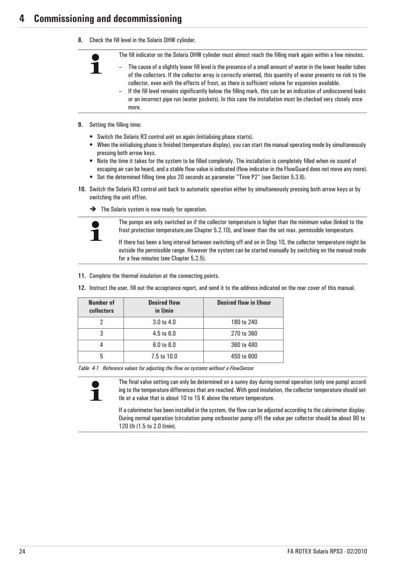
8. Check the fill level in the Solaris DHW cylinder.
9. Setting the filling time:
• Switch the Solaris R3 control unit on again (initialising phase starts).• When the initialising phase is finished (temperature display), you can start the manual operating mode by simultaneously
pressing both arrow keys.• Note the time it takes for the system to be filled completely. The installation is completely filled when no sound of
escaping air can be heard, and a stable flow value is indicated (flow indicator in the FlowGuard does not move any more).• Set the determined filling time plus 20 seconds as parameter "Time P2" (see Section 5.3.6).
10. Switch the Solaris R3 control unit back to automatic operation either by simultaneously pressing both arrow keys or by switching the unit off/on.
� The Solaris system is now ready for operation.
11. Complete the thermal insulation at the connecting points.
12. Instruct the user, fill out the acceptance report, and send it to the address indicated on the rear cover of this manual.
Table 4-1 Reference values for adjusting the flow on systems without a FlowSensor
The fill indicator on the Solaris DHW cylinder must almost reach the filling mark again within a few minutes.
– The cause of a slightly lower fill level is the presence of a small amount of water in the lower header tubes of the collectors. If the collector array is correctly oriented, this quantity of water presents no risk to the collector, even with the effects of frost, as there is sufficient volume for expansion available.
– If the fill level remains significantly below the filling mark, this can be an indication of undiscovered leaks or an incorrect pipe run (water pockets). In this case the installation must be checked very closely once more.
The pumps are only switched on if the collector temperature is higher than the minimum value (linked to the frost protection temperature,see Chapter 5.2.10), and lower than the set max. permissible temperature.
If there has been a long interval between switching off and on in Step 10, the collector temperature might be outside the permissible range. However the system can be started manually by switching on the manual mode for a few minutes (see Chapter 5.2.5).
Number of collectors
Desired flowin l/min
Desired flow in l/hour
2 3.0 to 4.0 180 to 240
3 4.5 to 6.0 270 to 360
4 6.0 to 8.0 360 to 480
5 7.5 to 10.0 450 to 600
The final valve setting can only be determined on a sunny day during normal operation (only one pump) accord-ing to the temperature differences that are reached. With good insolation, the collector temperature should set-tle at a value that is about 10 to 15 K above the return temperature.
If a calorimeter has been installed in the system, the flow can be adjusted according to the calorimeter display. During normal operation (circulation pump on/booster pump off) the value per collector should be about 90 to 120 l/h (1.5 to 2.0 l/min).
4 x Commissioning and decommissioning
25FA ROTEX Solaris RPS3 - 02/2010
4.2 Decommissioning
4.2.1 Temporary shutdown
The ROTEX Solaris installation can be shut down temporarily by switching off at the main switch on the Solaris R3 controller or by disconnecting the mains plug from the power supply.
If there is a danger of frost:– the ROTEX Solaris installation must be started up again
or– suitable antifreeze measures must be applied to the connected heating system and hot water storage tank (e.g. draining).
Draining the storage tank• Switch off the main switch and secure against restarting.• For GSU only: close the gas stop cock.• Connect the hose to the combined filling and drain cock on the Solaris return using the hose connection. • Drain the tank's water content.
4.2.2 Permanent decommissioning
• Shut down the ROTEX Solaris installation (see Chapter 4.2.1 "Temporary shutdown").• Disconnect the Control and pump unitRPS3 from all electrical and water connections.• Dismantle the Control and pump unit RPS3 in reverse order according to the installation manual (Chapter 3 "Installation").• Dispose of the Control and pump unit RPS3 in a professional manner.
CAUTION!
A heating system which is shut down can freeze in the event of frost and may suffer damage.• Drain the shut down heating system if there is danger of frost.
CAUTION!
Pumps that are switched off for a long time can seize.When Solaris installations are shut down temporarily, the function protecting the pumps from seizing (pump kick function) is also disabled.• Check for correct pump function when starting up again. Seized pumps can usually be freed up manually.
If there is a danger of frost for just a few days, the unit's excellent heat insulation means that the ROTEX Solaris DHW cylinder does not have to be drained, provided that the storage tank temperature is monitored regularly and does not fall below +3 °C. This does not, however, provide any protection against frost for the connected heat distribution system!

4 x Commissioning and decommissioning
26 FA ROTEX Solaris RPS3 - 02/2010
Notes on disposal
Due to the environmentally-friendly design of the Solaris system, ROTEX has complied with the requirements for environmentally-responsible disposal. During the disposal process, the only waste accrued is that which can be used for material or thermal recycling.
The materials used that are suitable for recycling can be sorted into individual types.
The designation of the product means that electrical and electronic products may not be disposed of together with unsorted domestic waste.
Proper disposal in compliance with the respective national regulations of the country of use is the responsibility of the user/owner.• Disassembly of the system, handling of coolant, oil and other parts may only be carried out by a qualified
fitter.• Disposal may only be carried out by a facility that specialises in reuse, recycling and recovery.Further information is available from the installation company or the responsible local authorities.

5 x Control unit operation
27FA ROTEX Solaris RPS3 - 02/2010
5 Control unit5.1 Operating and display elements
5.2 Controller operating principle
1 Main switch with indicator light2 Temperature and parameter display
(energy saving function: display illumination switches off 10 minutes after the last keypress)
3 Light for collector temperature display4 Light for solar flow temperature and
flow rate measurement (FLS)5 Light for storage cylinder temperature
display6 Light for solar return flow temperature
display7 Operating condition light for speed-
controlled circulation pump P1 (lights up when pump is operating; flashes when pump is throttled)
8 Operating condition light for booster pump P2 (lights up when pump is operating)
9 Up arrow for moving the temperature or parameter display up by one setting/increasing parameter settings
10 Down arrow for moving the temperature or parameter display down by one setting/decreasing parameter settings
11 Information key for accessing the information level (displays measured values, maximum values and calculated values) and OK key for confirming and storing settings in the setting menu
12 Controller housing13 Locking screws for unit housing (at rear)14 Rating plate
Unit may only be opened by authorised persons. Disconnect from mains supply before opening the housing.
Illustration 5-1 Operating and display elements
Because of constant improvements aimed at optimum use of the RPS3 system, the Solaris R3 controller has been equipped with an update function. Consequently some of the functions described in this chapter are only applicable to certain software versions. These functions are separately identified by symbols.
Software updates to the Solaris R3 controller may only be carried out by the ROTEX service technician.
The mains switch disconnects the Solaris R3 controller completely from the mains supply. Operating the mains switch requires greater pressure than actuating the operating buttons does.
5 x Control unit operation
28 FA ROTEX Solaris RPS3 - 02/2010
5.2.1 Pump operation
The Solaris system is operated throughout the year, without the need for manual intervention. The operation of the speed-controlled pump is controlled by the Solaris R3 controller. The operating and display elements are shown in Image 5-1.
Criteria for switching on:– Pump operation depends on the continuously measured difference between the
collector (TK) and return (TR) temperatures compared to the value set under the "Delta T On" parameter.– The pumps switch on when the temperature difference (=TK – TR) exceeds the value set under the "Delta T On" parameter
(e.g. Return temperature = 40 °C and "Delta T On" = 15 K; Collector temperature > 55 °C).– Operation of the upper booster pump (P2) depends on the value in seconds set for the "Time P2" parameter.
� If the correctly adjusted FlowSensor measures a stable flow before this time elapses, the solar installation is com-pletely filled with water.
– Automatic switchover from two pumps to one pump (circulation pump P1).– The control of the pump output depends on the difference between the flow and return temperatures of the ROTEX Solaris
installation.
Criteria for switching off:– The pumps switch off when the temperature difference falls below the value set under the "Delta T Off" parameter.
1st possibility: Normal switch-off when the "Filling time" ("Time P2" parameter) has elapsed and the difference between flow and return temperatures reaches the switch-off condition (TV – TR<"Delta T Off").2nd possibility: Rapid switch-off if the collector is cooling too quickly (TK – TR<"Delta T Off") during the "Filling time" ("Time P2" parameter).
– The maximum storage cylinder temperature set via the "TS max" parameter is reached (TS light flashes). In this case, the pumps can only be switched on again if the cylinder temperature drops by more than 2 K.
– The maximum permissible collector temperature set by the "TK perm" parameter is reached (TK light flashes). In this case, the pumps can only be switched on again if the collector temperature has fallen below the value of the "TK perm" parameter by more than 2 K.
– Defective FlowSensor.
5.2.2 Booster function for high collector temperatures
In addition to the standard circulation pump P1, the booster pump P2 is switched on automatically at a collector temperature of "TK max" = 70 °C (booster temperature).
� This increases the system pressure as well as the flow quantity, which enables more heat to be stored within a shorter time.
A heating technician can change the booster temperature by means of the "TK max" parameter. As soon as the collector temper-ature drops more than 5 K below “TK max”, pump P2 is switched off automatically again.
5.2.3 Switch-on inhibit functions
The switch-on inhibit functions prevent:– switching on again if the Solaris installation has been switched off automatically (TS light flashes) because the maximum
temperature set for the cylinder, "TS max", has been reached.– operation of the pumps if the collector temperature exceeds the value set by the heating engineer with the "TK perm" param-
eter (TK light flashes).
If the solar radiation continues after the pumps have been switched off due to the maximum cylinder temperature being reached, collector temperatures above 100 °C are possible . If, in such a situation, the cylinder temperature drops below the enable temperature ("TS max" – 2 K), for example because domestic hot water is consumed, the pumps are switched on again, provided that the collector temperature has dropped below the restart protection temperature set with the "TK perm" parameter by 2 K.
A rapid switch-off will not take place if the frost protection is active (TK<0 °C within the last 24 h). The pumps are operated over a longer period so that the connecting pipes are sufficiently warmed up that no icing can occur.
In this case, however, a considerably higher collector temperature must be reached before the pumps switch on.
From The inhibit time function prevents the pumps from being enabled again after a switch-off condition has occurred, until the inhibit time set under the "Time SP" parameter (0 – 600 s) has elapsed.

5 x Control unit operation
29FA ROTEX Solaris RPS3 - 02/2010
This means:– cycling of the system can be minimised.– the collector can reach a higher temperature.– the flow temperature does not drop below the switch-off condition during filling and the system adjusts more quickly.
5.2.4 Pump kick function
The pump kick is a pump protection function for longer periods of bad weather. It is active once after each 24-hour period of standstill.
� Both pumps P1 and P2 are switched on briefly for a few milliseconds to prevent them from seizing.
5.2.5 Manual operation
The installation can be switched on manually for the time stored under the "H/A" parameter for commissioning and test purposes. In this case, all control functions are disabled and both pumps run continuously at the set speed, regardless of the system temper-atures.
• Manual operation is toggled on/off by pressing both arrow keys simultaneously (>1 s).
5.2.6 Solaris FlowSensor
The optional FlowSensor (FLS) is used to measure flow rate "V" and flow temperature "TV".With the sensor connected and working:– the measured values "V" and "TV" are displayed.– after the filling procedure, the control unit works with the actual system temperature difference between inflow and return
flow temperatures.When the system has detected the FlowSensor, and if a sensor is faulty or is removed, the display shows a corresponding error message (see Chapter 6.1). The system then works in the emergency mode without the FlowSensor.
If the pumps are switched on at collector temperatures over 100 °C (TK perm > 100 °C), the return water evaporates as soon as it reaches the collector. The reduction of the excess heating capacity in the collectors and the associated boiling noise caused by evaporation can last several minutes.
In a correctly installed Solaris system, the steam escapes into the storage cylinder, where most of it condenses again. Similarly, a slightly increased consumption of cylinder water due to escaping steam is a normal operating condition.
If pump P1 operates alone without a FlowSensor and without any switch-off condition or booster function occurring, P2 is switched on every two hours for the time specified in the "Time P2" parameter.
This prevents damage to pump P1 should an undetected break in the flow occur.
CAUTION!
Uncontrolled manual operation can result in heat loss, excessively high storage cylinder temperatures, and even frost damage in extremely cold situations.
Up to The FlowSensor can be activated and deactivated with the "FLS active" parameter.From If the controller detects a FlowSensor after a new installation or a technician reset, the value "20" is
automatically set for the "FLS active" parameter. The correct parameter value for the FlowSensor installed in the system must always be checked and set if necessary (see Table 5-1). The FlowSensor can be deactivated by entering the parameter value "0".
5 x Control unit operation
30 FA ROTEX Solaris RPS3 - 02/2010
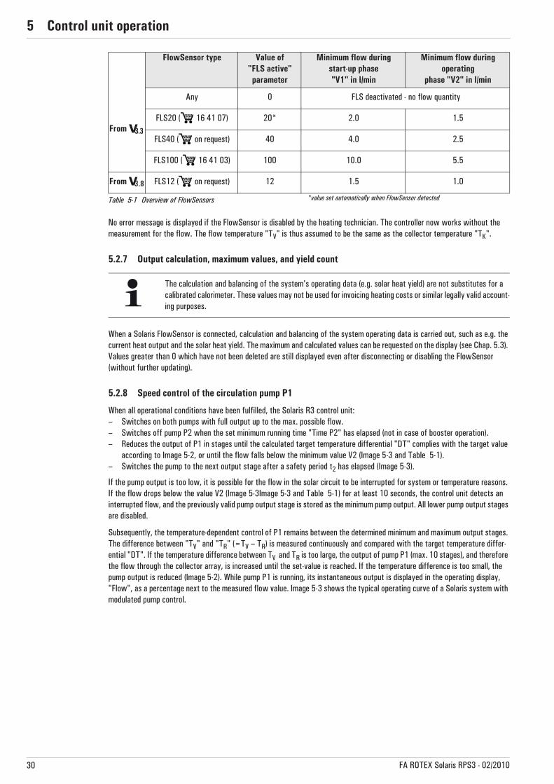
No error message is displayed if the FlowSensor is disabled by the heating technician. The controller now works without the measurement for the flow. The flow temperature "TV" is thus assumed to be the same as the collector temperature "TK".
5.2.7 Output calculation, maximum values, and yield count
When a Solaris FlowSensor is connected, calculation and balancing of the system operating data is carried out, such as e.g. the current heat output and the solar heat yield. The maximum and calculated values can be requested on the display (see Chap. 5.3). Values greater than 0 which have not been deleted are still displayed even after disconnecting or disabling the FlowSensor (without further updating).
5.2.8 Speed control of the circulation pump P1
When all operational conditions have been fulfilled, the Solaris R3 control unit:– Switches on both pumps with full output up to the max. possible flow. – Switches off pump P2 when the set minimum running time "Time P2" has elapsed (not in case of booster operation).– Reduces the output of P1 in stages until the calculated target temperature differential "DT" complies with the target value
according to Image 5-2, or until the flow falls below the minimum value V2 (Image 5-3 and Table 5-1). – Switches the pump to the next output stage after a safety period t2 has elapsed (Image 5-3).
If the pump output is too low, it is possible for the flow in the solar circuit to be interrupted for system or temperature reasons. If the flow drops below the value V2 (Image 5-3Image 5-3 and Table 5-1) for at least 10 seconds, the control unit detects an interrupted flow, and the previously valid pump output stage is stored as the minimum pump output. All lower pump output stages are disabled.
Subsequently, the temperature-dependent control of P1 remains between the determined minimum and maximum output stages. The difference between "TV" and "TR" (=TV – TR) is measured continuously and compared with the target temperature differ-ential "DT". If the temperature difference between TV and TR is too large, the output of pump P1 (max. 10 stages), and therefore the flow through the collector array, is increased until the set-value is reached. If the temperature difference is too small, the pump output is reduced (Image 5-2). While pump P1 is running, its instantaneous output is displayed in the operating display, "Flow", as a percentage next to the measured flow value. Image 5-3 shows the typical operating curve of a Solaris system with modulated pump control.
FlowSensor type Value of"FLS active"
parameter
Minimum flow during start-up phase"V1" in l/min
Minimum flow during operating
phase "V2" in l/min
From
Any 0 FLS deactivated - no flow quantity
FLS20 ( 16 41 07) 20* 2.0 1.5
FLS40 ( on request) 40 4.0 2.5
FLS100 ( 16 41 03) 100 10.0 5.5
From FLS12 ( on request) 12 1.5 1.0
Table 5-1 Overview of FlowSensors *value set automatically when FlowSensor detected
The calculation and balancing of the system's operating data (e.g. solar heat yield) are not substitutes for a calibrated calorimeter. These values may not be used for invoicing heating costs or similar legally valid account-ing purposes.
3.83.8

5 x Control unit operation
31FA ROTEX Solaris RPS3 - 02/2010
Illustration 5-3Example of modulated operation with inhibition of lower pump stages due to flow interruptions on installations with FlowSensor
DT Target temperature differential (calculated for the operating point)
P1 Circulation pumpS1 Upper target temperature difference (“temperature
difference 1")S1 Lower target temperature difference (“temperature
difference 2")TK Collector temperatureT1 Frost protection temperature ("T frost")
T2 Booster temperature ("TK max")T3 Switch-on inhibit temperature (“TK perm”)— Target temperature differential- - Switching limits for pump modulation� Pump output is increased� Pump output is reduced
Illustration 5-2 Pump output control as a function of temperature difference
If the controller is switched off and on again:– automatically inhibited pump speeds will be enabled again.– the installation will be automatically readjusted.– manually inhibited pump speeds (see Chapter 5.3.7) will continue to be inhibited.
A Start phaseB Operating phase (modulation)C Interrupted flowD Low pump output stages are automatically
disabled when flow is interruptedP1 Circulation pumpP2 Booster pumpV Solar circuit flow
V1 Minimum flow in the start phaseV2 Minimum flow in the operating phase
t Timet1 Maximum starting time of booster pump P2
("Time P2")t2 Settling timet3 Interruption detection period (10 s)
5 x Control unit operation
32 FA ROTEX Solaris RPS3 - 02/2010
5.2.9 Overall reset function
The controller responds to an overall reset with a new start (self-test), whereby all parameters are set to their default (factory) values, and all disabled pump output stages are enabled. A reset is carried out by:
• Via menu path: activation by the heating engineer in the "System" setup menu.• Rapid access: simultaneously press the OK and the arrow buttons.
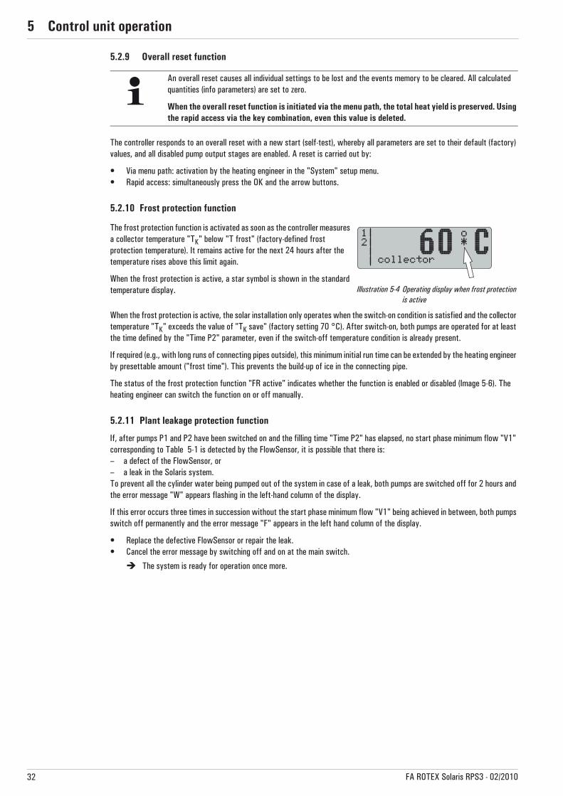
5.2.10 Frost protection function
When the frost protection is active, the solar installation only operates when the switch-on condition is satisfied and the collector temperature "TK" exceeds the value of "TK save" (factory setting 70 °C). After switch-on, both pumps are operated for at least the time defined by the "Time P2" parameter, even if the switch-off temperature condition is already present.
If required (e.g., with long runs of connecting pipes outside), this minimum initial run time can be extended by the heating engineer by presettable amount ("frost time"). This prevents the build-up of ice in the connecting pipe.
The status of the frost protection function "FR active" indicates whether the function is enabled or disabled (Image 5-6). The heating engineer can switch the function on or off manually.
5.2.11 Plant leakage protection function
If, after pumps P1 and P2 have been switched on and the filling time "Time P2" has elapsed, no start phase minimum flow "V1" corresponding to Table 5-1 is detected by the FlowSensor, it is possible that there is:– a defect of the FlowSensor, or– a leak in the Solaris system.To prevent all the cylinder water being pumped out of the system in case of a leak, both pumps are switched off for 2 hours and the error message "W" appears flashing in the left-hand column of the display.
If this error occurs three times in succession without the start phase minimum flow "V1" being achieved in between, both pumps switch off permanently and the error message "F" appears in the left hand column of the display.
• Replace the defective FlowSensor or repair the leak.• Cancel the error message by switching off and on at the main switch.
� The system is ready for operation once more.
An overall reset causes all individual settings to be lost and the events memory to be cleared. All calculated quantities (info parameters) are set to zero.
When the overall reset function is initiated via the menu path, the total heat yield is preserved. Using the rapid access via the key combination, even this value is deleted.
The frost protection function is activated as soon as the controller measures a collector temperature "TK" below "T frost" (factory-defined frost protection temperature). It remains active for the next 24 hours after the temperature rises above this limit again.
When the frost protection is active, a star symbol is shown in the standard temperature display. Illustration 5-4 Operating display when frost protection
is active
5 x Control unit operation
33FA ROTEX Solaris RPS3 - 02/2010
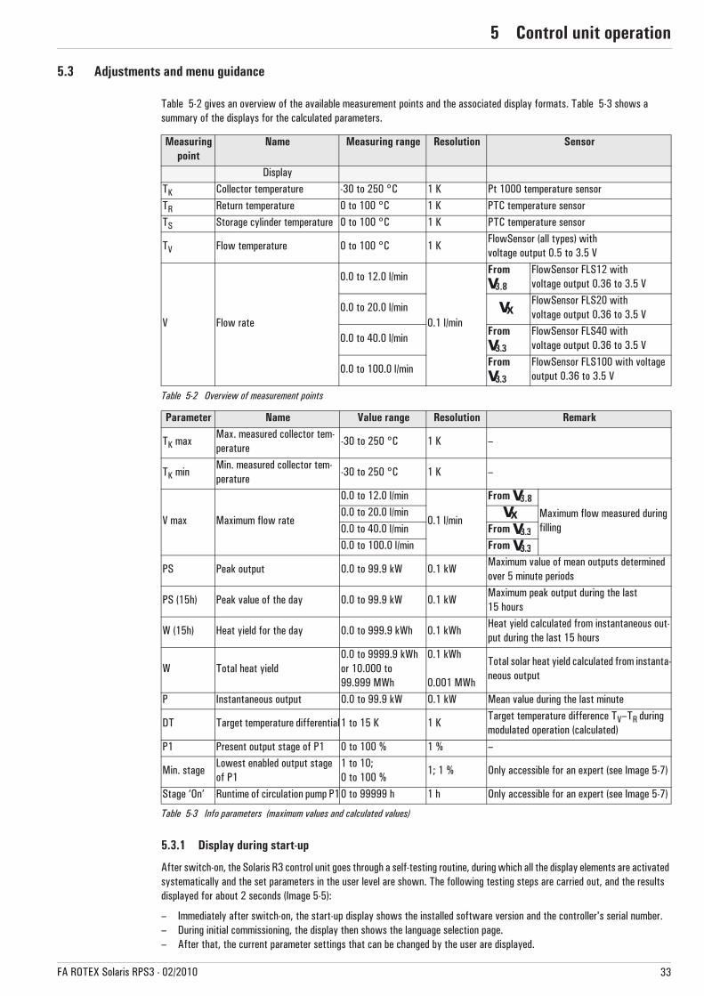
5.3 Adjustments and menu guidance
Table 5-2 gives an overview of the available measurement points and the associated display formats. Table 5-3 shows a summary of the displays for the calculated parameters.
Table 5-2 Overview of measurement points
Table 5-3 Info parameters (maximum values and calculated values)
5.3.1 Display during start-up
After switch-on, the Solaris R3 control unit goes through a self-testing routine, during which all the display elements are activated systematically and the set parameters in the user level are shown. The following testing steps are carried out, and the results displayed for about 2 seconds (Image 5-5):
– Immediately after switch-on, the start-up display shows the installed software version and the controller's serial number.– During initial commissioning, the display then shows the language selection page.– After that, the current parameter settings that can be changed by the user are displayed.
Measuring point
Name Measuring range Resolution Sensor
DisplayTK Collector temperature -30 to 250 °C 1 K Pt 1000 temperature sensorTR Return temperature 0 to 100 °C 1 K PTC temperature sensorTS Storage cylinder temperature 0 to 100 °C 1 K PTC temperature sensor
TV Flow temperature 0 to 100 °C 1 KFlowSensor (all types) withvoltage output 0.5 to 3.5 V
V Flow rate
0.0 to 12.0 l/min
0.1 l/min
From FlowSensor FLS12 with voltage output 0.36 to 3.5 V
0.0 to 20.0 l/minFlowSensor FLS20 with voltage output 0.36 to 3.5 V
0.0 to 40.0 l/minFrom FlowSensor FLS40 with
voltage output 0.36 to 3.5 V
0.0 to 100.0 l/minFrom FlowSensor FLS100 with voltage
output 0.36 to 3.5 V
Parameter Name Value range Resolution Remark
TK maxMax. measured collector tem-perature
-30 to 250 °C 1 K –
TK minMin. measured collector tem-perature
-30 to 250 °C 1 K –
V max Maximum flow rate
0.0 to 12.0 l/min
0.1 l/min
From
Maximum flow measured during filling
0.0 to 20.0 l/min0.0 to 40.0 l/min From 0.0 to 100.0 l/min From
PS Peak output 0.0 to 99.9 kW 0.1 kWMaximum value of mean outputs determined over 5 minute periods
PS (15h) Peak value of the day 0.0 to 99.9 kW 0.1 kWMaximum peak output during the last 15 hours
W (15h) Heat yield for the day 0.0 to 999.9 kWh 0.1 kWhHeat yield calculated from instantaneous out-put during the last 15 hours
W Total heat yield0.0 to 9999.9 kWhor 10.000 to 99.999 MWh
0.1 kWh
0.001 MWh
Total solar heat yield calculated from instanta-neous output
P Instantaneous output 0.0 to 99.9 kW 0.1 kW Mean value during the last minute
DT Target temperature differential1 to 15 K 1 KTarget temperature difference TV–TR during modulated operation (calculated)
P1 Present output stage of P1 0 to 100 % 1 % –
Min. stageLowest enabled output stage of P1
1 to 10;0 to 100 %
1; 1 % Only accessible for an expert (see Image 5-7)
Stage ‘On’ Runtime of circulation pump P10 to 99999 h 1 h Only accessible for an expert (see Image 5-7)
3.83.8
3.83.8

5 x Control unit operation
34 FA ROTEX Solaris RPS3 - 02/2010
– When the operating display appears, the self test is complete.– For safety reasons, the functions of the pumps and their operating condition lights can only be checked manually
(see Section 5.2.5).
5.3.2 Display during operation
During operation, the display shows the system temperatures, maximum values, and calculated values. After showing the start display, the Solaris R3 controller switches automatically to operation display mode, an operation value is displayed and the relevant light is illuminated. • Pressing the arrow keys permits navigating between the four measured temperature values and the flow rate measurement
(see Table 5-2 and Table 5-6). • Pressing the Info key displays the maximum values and the calculated values (see Table 5-3).
The left-hand column of the display shows the following status information :– "1" in the first line, circulation pump P1 running.– "2" in the 2nd line, booster pump P2 active.– "B" in the 3rd line, burner inhibit contact active (see Section 5.3.9) or an error status (see Chap. 6.2). – "H" in the 4th line, manual operation active.
5.3.3 Setup menu
The parameters of the Solaris R3 control unit are displayed and can be changed in this menu. • Pressing the OK key once (>2 s) either activates the menu or returns to the operating display. Briefly pressing the key
confirms a selection, opens the next menu item, or displays “Saved” for about 1 second after a value has been changed.• In the selected parameter display, pressing the OK key switches over to the parameter changing mode.
The first line of the menu (Image 5-7) shows the active menu item, whilst in the left-hand column a cursor (">") points to the next lower menu item or to a parameter. From here, you navigate to the respective menu tree by means of the arrow keys: up (+ key) or down (– key). The adjusted value can be changed accordingly with the arrow keys. Briefly pressing an arrow key changes the value by one step, and continuous pressing speeds up the change. After changing the required parameter, and moving down through the entire parameter list, then display returns to the selection menu "Selection 2/2", and from there to the operating display (see Image 5-7). The control unit starts working with the changed parameter value(s) immediately. The display always returns to the operating display mode after 10 minutes, provided that no key is pressed during this time.
The measurement or info display that has been accessed remains active as long as no manual adjustments are made or no event according to Table 6 -2 calls up a different form of display. It is also reactivated after param-eter changes or switching off and on. If info parameters are displayed, no measuring point indicator lights are activated.
Illustration 5-5 Display during start-up Illustration 5-6 Display during operation
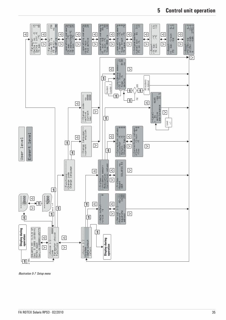
5 x Control unit operation
35FA ROTEX Solaris RPS3 - 02/2010
Illustration 5-7 Setup menu
5 x Control unit operation
36 FA ROTEX Solaris RPS3 - 02/2010
5.3.4 Password protection
The Expert level of the setup menu is protected by a password, which must be entered at the beginning of the setup menu. Also the Operator level can be protected. The Operator and Expert levels are identified by different colours in Image 5-6.
Alternative fast access to the setup menu:After switching on the controller, during the start display, with a long press on the "up" arrow key (+).
As long as the system is being operated manually, no further password entry is required. Passwords remain valid for about 10 minutes after the last key has been pressed. After entering the password for the required level, the following display appears for about 2 seconds:– "Operator OK",– "Expert OK" or– "Incorrect password".
Operator passwordWhen delivered, this password is not activated in the Solaris R3 control unit. By entering a 4-digit number code, all the parameters adjustable in Operator level are protected against unauthorised access (child protection or caretaker function). The parameters of the Operator level can only be changed with the correct Operator password or if password protection has been disabled.
The activation and changing or creation of the Operator password are performed in the menu path: "Selection 1/2" -> "Functions" -> "Change code" (see Image 5-7):• Enter the old password in the field "present 0000”, and the new password in the field "new 0000”. Hereby, every digit must
be confirmed with the OK key.• When assigning a new password, it must be entered in the field "present 0000” as well as in the field "new 0000”.If the Operator password is enabled, the menu item "Selection 1/2" only shows "Password 0000". The Operator password is enabled only after 10 minutes or after a restart of the Solaris R3 control unit.
Expert passwordThe Expert password is entered in the menu item "Selection 1/2" under "Password 0000". It provides access to all the important system parameters required by the expert in the setup menu (see Image 5-7).
5.3.5 Language selection
During initial commissioning or after an overall reset, the display (Image 5-5) is stopped during the start-up, and a language selection is requested. • Use the arrow keys to select your language, and confirm it with the OK key. Another language can be selected retrospectively in the set-up menu in the menu path: "Selection 1/2" -> "Functions" -> "Change language" (Image 5-7).
Alternative fast access to the language selection:Simultaneously press the OK button and the "up" arrow button (+).
5.3.6 Adjusting and resetting parameters
Parameters are adjusted according to Image 5-7. All adjustable parameters are displayed in Table 5-5 with access level, adjustment range, and factory setting. The menu item: "Selection 1/2" -> "Parameter selection" -> "Reset" allows the maximum values and calculated values (see Table 5-5) to be reset. Hereby, the selected max. value is set to zero immediately with the OK key. The arrow key “Down” cancels this operation, and the cursor goes back to the left. The OK key confirms the selection. Repeated pressing of the key “Down” takes you to the field "Selection 2/2". Confirming "Back" returns you to the operating display.
The overall reset function can be initiated via the menu path: "Selection 2/2" -> "System" -> "Reset". The system will then be restarted (see also Section .5.2.9)
An overall reset causes all individual settings to be lost and the events memory to be cleared. All calculated quantities (Info parameters) are set to zero.
When the overall reset function is initiated via the menu path, the total heat yield is preserved. Using the rapid access via the key combination, even this value is deleted.

5 x Control unit operation
37FA ROTEX Solaris RPS3 - 02/2010
5.3.7 Manual adjustment of pump speed control
With some output stages of the speed-controlled pump P1 it is possible that noise problems arise. The present output of the selected stage is displayed as a percentage in the bottom line "Flow" of the operating display (see Image 5-6). • Make a note of the problematic output stage. • Navigate to "Stage" via the menu path: "Selection 2/2" -> "System" -> "Modulation" (see Image 5-7).Here, up to 10 speed ranges can be disabled. Next to the reference number of the output stage (starting with 01 for the lowest output) and the operating status, the output of the relevant stage is displayed as a percentage under “Output”.
• Disable the noisy stage by setting the "Active" parameter to "No".
� From now on, this stage will be skipped during control of pump P1. The inhibit remains even after the controller is switched off and on again. It can be cancelled again by setting the "Active" parameter to "Yes" or by means of the overall reset function.
5.3.8 Correcting values for measurement points
If the measurement value of a sensor deviates from the true value, it can be compensated by means of a correcting value.
• Find the correcting parameter via the menu path: "Selection 2/2" -> "System" -> "Correction values" (see Image 5-7) and change the values according to Table 5-4.
Table 5-4 Correcting values
5.3.9 Burner inhibit contact
This contact controls an external heat generator in such a way that under favourable weather conditions, the storage cylinder is not heated by the external source. For this purpose, the connecting cable BSKK ( 16 41 10), which is available as an accessory, is required. If the Solaris system reaches an instantaneous output value (adjustable by an expert via menu path: "Selection 1/2" -> "Parameter selection" -> "Operating parameter "P min"") or if the storage cylinder is heated to a minimum temperature (adjustable by an expert via operating parameter "TS min" see Table 5-5) a contact disables e.g. the burner. The parameter setting for the burner inhibit contact is described in Image 5-7.
In the following example (Image 5-8) an imaginary course for the cylinder temperature is presented.
At time "t1", the minimum temperature for burner stop defined in operating parameter "TS min" is exceeded for the first time. As the cylinder temperature "TS" falls below this value once more shortly afterwards, this does not result in activation of the burner inhibit contact.
After the cylinder temperature "TS" is permanently exceeded at time "t2", this results in the activation of the burner inhibit contact with the delay "VBSK" at time "t3". In a similar way, the burner inhibit contact is only deactivated at time "t6".
Name Access level Measurement & ad-justing range
Factory setting Step width
Collector temperature correction
Expert
-9 to +9 0 K 1 K
Return flow temperature correction -9 to +9 0 K 1 K
Storage cylinder temperature correc-tion
-9 to +9 0 K 1 K
Flow temperature correction -9 to +9 0 K 1 K
Flow rate correction -2 to +2 0 l/min 0.1 l/min
From It is possible to set a delay for the switching time of the burner inhibit contact by means of the "Time VBSK" parameter. If the minimum cylinder temperature "TS min" is exceeded or if the preset minimum instantaneous output for burner stop "P min" is exceeded, the burner inhibit contact only switches after the set delay time has elapsed (see Image 5-8 for an example).
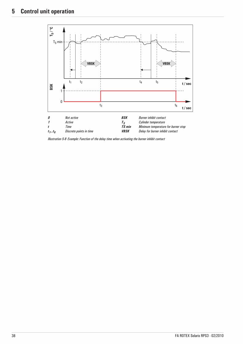
5 x Control unit operation
38 FA ROTEX Solaris RPS3 - 02/2010
0 Not active1 Activet Timet1...t6 Discrete points in time
BSK Burner inhibit contactTS Cylinder temperatureTS min Minimum temperature for burner stopVBSK Delay for burner inhibit contact
Illustration 5-8 Example: Function of the delay time when activating the burner inhibit contact

5 x Control unit operation
39FA ROTEX Solaris RPS3 - 02/2010
5.4 Recommended settings
5.4.1 Standard parameter values, recommended adjustment ranges
The following table summarises the default (factory) settings as well as possible and recommended adjustment ranges for the Solaris system parameters.
Table 5-5 Overview of parameters
Parameter Name Access level Setting range Recommended adjustment
range
Factory setting
Step width
Delta T On Switch-on temperature difference
Operator
1...80(>"Delta Off")
10 to 15 K 15 K 15 K
Delta T Off Switch-off temperature difference1...20
(<"Delta On")2 to 5 K 2 K 1 K
TS max Max. storage cylinder temperature 20 to 85 °C 75 to 85 °C 80 °C 1 K
Time P2Minimum start-up run time for the booster pump P2
10 to 999 KFilling time
+20 s150 s 1 s
Time SP Inhibit time for pumps
Expe
rt
From 0 to 600 s — 30 s 1 s
TK maxBooster temperature(maximum collector temperature)
20 to 110 °C — 75 °C 1 K
TK permSwitch-on inhibit temperature (max. permissible operating collec-tor temp.)
90 to 250 °C — 95 °C 1 K
TR frost Frost protection temperatureUp to
10 to 60 °C — 25 °C 1 KTR min Minimum return temperature From
T frostLimiting collector temperature for activating the frost protection function
0 to 10 °C — 0 °C 1 K
TK saveMinimum collector temperature for enabling pump operation when the frost protection function is active
50 to 80 °C — 70 °C 1 K
Time frostAdditional start-up run time for the booster pump P2 when the frost protection function is active
0 to 600 s — 0 s 1 s
FR active Status of frost protection function Yes/No Automatic No —
H/AAutomatic return from manual to automatic operation
1 to 900 l/min — 30 min 1 min
FLS enabled FlowSensor activation
Up to Yes/No Yes Yes —
From
0 to 100
FLS12: 12
No FLS: 0With FLS: 20
0, 12, 20, 40, 100From
FLS20: 20FLS40: 40
FLS100: 100P min Min. output for burner stop 0.0 to 99.9 kW — 99.9 kW 0.1 kW
TS minMinimum temperature for burner stop
0 to 99 °C — 99 °C 1 K
Time VBSK Delay for burner inhibit contactFrom
10 to 600 s — 120 s 10 s
During commissioning, the system parameters must be adjusted individually to suit the installed system, and might need fine tuning during subsequent operation. Usually, the system will operate with the default settings.
3.73.7
3.83.8
3.83.8

5 x Control unit operation
40 FA ROTEX Solaris RPS3 - 02/2010
The following notes will help to determine the optimum settings, and guarantee an optimum heat yield with low power consumption:• Adjust the switch-on temperature difference "Delta T On" so that the system remains in operation under constant solar
radiation conditions, and does not switch off immediately when the collector temperature drops due to heat removal. The lower this value can be adjusted, the longer will be the operating periods with a correspondingly higher heat yield. If the adjusted switch-on temperature difference is too low, the collector will already cool down so far during filling, that the switch-off temperature difference is reached.
� The pumps are switched off immediately, with resulting lower heat yield and higher power consumption.
• Adjust the switch-off temperature difference "Delta T Off" so that the heat yield obtainable at the switch-off point is higher than the electrical power required to drive the pump.
� As the pump's power consumption is practically independent of the size of the connected collector array, but the achievable heat yield is directly proportional to the number of collectors, this parameter value must be set higher with fewer collectors, and lower with more collectors.
• Adjust the operating period "Time P2" of the booster pump P2 so that the entire cross-section of the inflow pipe is filled with water under all operating conditions. Determine the time required between hearing escaping air when the pumps are switched on, and water entering the storage cylinder, and add a safety margin of 20 seconds. The filling period depends on the adjusted flow rate, the number of collectors, system height, and the length of the connecting pipe.
• The max. storage cylinder temperature "TS max" is adjusted according to individual requirements. The higher the parameter value, the higher the heat storage capacity available and, therefore, the potential performance of the Solaris system.
System switch-on involving steam generation can often be disconcerting for the operator. The switch-on inhibit temperature "TK perm" is preset at the factory to prevent boiling noises and the escape of steam. The Solaris control unit only switches the pumps on again, when the collector temperature has fallen 2 Kelvin below the adjusted parameter value. Consequently, the system runs without evaporation in the collector. However, on a cloudless day, this can lead to a situation where the system only switches on again in the late afternoon, although the storage cylinder temperature permits additional heating.• For maximum heat yield, the "switch-on inhibit temperature parameter" should be adjusted to a value above 100 °C, which
disables the inhibit function. In this case, the operator must be informed that there will be considerably more boiling noise and steam hammer during filling.
5.4.2 Other adjustments of your Solaris system
The following adjustment notes only apply for operation without a FlowSensor:
In this case, a FlowGuard (see Chapter 2-3) should be fitted to the flow connection of the Solaris storage cylinder. Hereby, the water flow should be adjusted so that the throughput of every collector is 90 to 120 l/h. Adjust the flow rate either by selecting a speed range for pump P1 and/or by adjusting the FlowGuard (regulating valve with flow rate indicator). Guide values for the correct valve/pump settings are given in Table 5-6.
For indirect monitoring of the flow rate, always observe the system temperatures during normal operation. Under optimum solar radiation conditions (cloudless sky, clear air, sun about vertical to the collector surface), the temperature increase in the collector should be about 10 to 15 K. During operation of pump P1, and with a return flow temperature of e.g. 50 °C, the collector temper-ature should be about 60 to 65 °C. If a calorimeter is installed , the flow rate can be adjusted by means of a direct measurement while operating a pump.
WARNING!
Temperatures over 60 °C can be present in the Solaris DHW cylinder.• Install scalding protection.
– Scalding protection VTA 32 ( 15 60 15)– Screw fittings set 1" ( 15 60 16)
When operating the Solaris system with a FlowSensor, the flow rate in the solar circuit is adapted continuously to requirements by means of the temperature-difference dependent control of pump P1.

5 x Control unit operation
41FA ROTEX Solaris RPS3 - 02/2010
Table 5-6 Adjusting the flow rate of the FlowGuard (FLG)
5.4.3 Recommended settings for auxiliary heating via external heat sources or the electric heater, burner inhibit contact
For the highest performance potential:• Use the external heat source or the electric heater sparingly to heat up the Solaris DHW cylinder, and even then only to bring
it to an adequate temperature.• Restrict the recharging times by means of timer programmes:
a) Determine optimum times for "normal use" resulting from regular consumption behaviour.b) Enable recharging, depending on the connected heat source, a half to two hours before the usual consumption time.
• The charging time should be limited so that the cylinder does not need to be directly heated after a normal consumption cycle.
• With larger amounts of hot water and to ensure the required convenience even during out of the ordinary consumption times, the temperature in the hot water zone must be sufficiently high, or the heat source for charging must be enabled, e.g. by switching to a different timer program.
Setting the cylinder charging temperature• Set the hot water target temperature so that sufficient hot water is available for drawing (e.g., for 1 shower) with the
lowest possible setting. This setting will guarantee the maximum heating of the hot water by the solar installation for a certain withdrawal quantity.
Heating by means of an external heat generatorDepending on the heating requirements (related to the building's insulation standard, outdoor temperature, and desired room temperatures) and the installed collector surface, it might be expedient to disable the external heat generator by fitting a burner inhibit contact. For this purpose, also if the heater control demands additional heat:
• adjust the "P min", "TS min" and "Time VBSK" operating parameters (see Section 5.3.9) so that the external heating source does not heat– if the collectors are supplying a minimum amount of heat, or – the storage cylinder has reached a sufficiently high temperature.
Number of collec-tors
Desired flow in l/min Desired flow in l/min
2 3.0 to 4.0 180 to 240
3 4.5 to 6.0 270 to 360
4 6.0 to 8.0 360 to 480
5 7.5 to 10.0 450 to 600
To ensure fast and safe filling of the system, the booster pump P2 should always be operated in stage 3. If possible, the circulation pump P1 should be operated at a lower speed, it the system height H (height difference between mounting floor level of the Solaris DHW cylinder and the upper collector edge) is not more than 10 m (for stage 2) or 8 m (for stage 1), and the flow rate is still sufficient.
Even if the flow rate and the switch-on difference "Delta T On", have been adjusted correctly, and the weather conditions are ideal, the Solaris system sometimes switches off. With a rising or setting sun, and an increasing storage cylinder temperature, the collector temperature gradually falls after the pumps have been switched on, i.e. the switch-off conditions are met. Due to the continued solar radiation, the collector temperature increases again, the pumps are started, and the system cycles because the solar radiation is insufficient for continuous operation. The FlowSensor reduces this effect by regulating the pump speed.
The optimum charging temperature depends on personal needs; frequently a storage cylinder temperature of 50 °C is adequate. An average shower requires about 30 to 50 l of hot water with an outlet temperature of 40 °C. The cold water entering the cylinder during the shower must be heated in the Solaris storage cylinder using the flow heater principle.

5 x Control unit operation
42 FA ROTEX Solaris RPS3 - 02/2010
5.4.4 Tips for optimised user behaviour
Hot water needs and user behaviour are highly individual. The higher the desired storage cylinder temperature is, and the longer the periods for non-solar charging heating have been adjusted, the more will the storage potential for solar heat generation be limited. Conscious user behaviour that is adapted to the special strengths of the Solaris hot water cylinder will minimise the energy consumption of non-solar charging operations.
• Use modern and convenient shower heads with flow rates of 5 - 7 l/min.
� The lower flow rate (hot water consumption per minute) results in a reduced need for supplementary heating, and there-fore a larger amount of hot water at a higher temperature.
• Reduce the consumption times.
� Lower energy consumption.
• Start filling the bathtub only with hot water.
� After the hot water stored in the Solaris DHW cylinder has been drawn, the hot water discharge temperature drops slightly, and the water is mixed in the bathtub. In this way, the storage capacity is used in an optimal manner with a minimum charging temperature; an adequate amount of hot water is available.
5.4.5 Domestic water hygiene
If no hot water is drawn for several days, and if the storage cylinder temperature is not maintained at a minimum of 60 °C by the Solaris system, a one-time temperature increase to above 60 °C or draining the stored hot water (25 l) is recommended for hygienic reasons (Legionella protection).

6 x Faults and malfunctions
43FA ROTEX Solaris RPS3 - 02/2010
6 Faults and malfunctions6.1 Display of events
Event code
Plain text display
Description Status display
(flashes)
Light (flashes)
Consequence
0 Collector Collector sensor: short circuit or break K TK
Permanent switch-off of P1 and P21 Return flow Return sensor: short circuit or break R TR
2Storage cylinder
Cylinder sensor: short circuit or break S TS
3 Flow FlowSensor: short circuit or break DOperation without FlowSensor
4 Inflow FlowSensor: short circuit or break V
5 A/D Internal A/D converter fault G
Permanent switch-off of P1 and P26 Supply Internal supply voltage fault G
7 Reference Internal reference voltage fault G
8 Reset Overall reset was carried outParameters set to default values, calculated values and event entries cleared (see Chapter 5.2.9), system restarted
12 Start flow
Minimum flow rate V1 (see Table 5-1) was not achieved in the start phase after "Time P2" elapsed (see Chapters 5.2.1 and 5.2.11 for description)
WP1 and P2 switched off for 2 h; after that, ready for operation again or Status "F"
F TVP1 and P2 switched off permanently if event occurs 3x in succession without an intervening successful start.
13 TS > TsmaxMaximum cylinder temperature ("TS max") exceeded (see Chapters 5.2.1 and 6.2 for description)
TS
Temporary switch-off of P1 and P214 TR >> TSTR - TS > 10 K and TR > 40 °C(see Chapter 6.2 for description)
TR
15TK >
Tk perm
Maximum permissible collector temperature ("TK perm") exceeded - (see Chapters 5.2.1 and 6.2 for description)
TK
16 InterruptInterruption in flow detected during operat-ing phase (V < V2, see Chapter 5.2.8 and Table 5-1)
Temporary switch-off of P1 and P2 (at least during stabilisation period), disabling of present and all lower pump output stages, refilling with P1 and P2 with "Time P2" with next switch-on condition.
202 P-on reset Switch onRestart, all parameter settings and Info parameters are preserved, automatically inhibited pump output stages are enabled once more.
204 Brown-outReset due to impermissible reduction in mains voltage
Restart according to Code 202.
205 WatchdogReset due to external disturbances (e.g., overvoltage caused by thunderstorms)
Restart according to Code 202.
Table 6 -1 Events memory
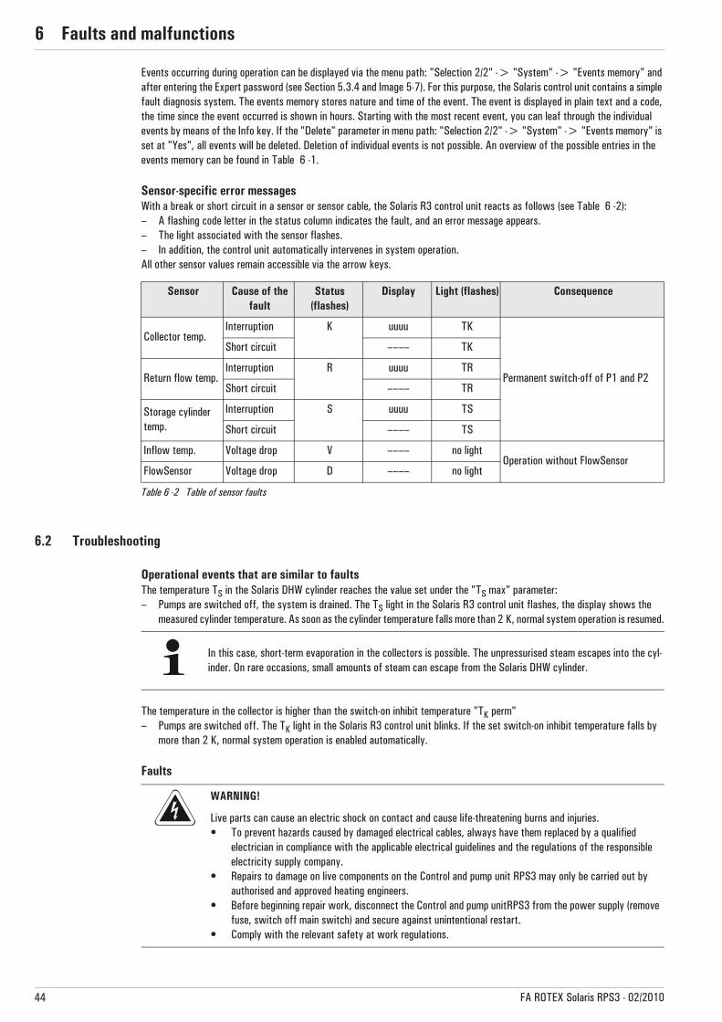
6 x Faults and malfunctions
44 FA ROTEX Solaris RPS3 - 02/2010
Events occurring during operation can be displayed via the menu path: "Selection 2/2" -> "System" -> "Events memory" and after entering the Expert password (see Section 5.3.4 and Image 5-7). For this purpose, the Solaris control unit contains a simple fault diagnosis system. The events memory stores nature and time of the event. The event is displayed in plain text and a code, the time since the event occurred is shown in hours. Starting with the most recent event, you can leaf through the individual events by means of the Info key. If the "Delete" parameter in menu path: "Selection 2/2" -> "System" -> "Events memory" is set at "Yes", all events will be deleted. Deletion of individual events is not possible. An overview of the possible entries in the events memory can be found in Table 6 -1.
Sensor-specific error messages With a break or short circuit in a sensor or sensor cable, the Solaris R3 control unit reacts as follows (see Table 6 -2):– A flashing code letter in the status column indicates the fault, and an error message appears.– The light associated with the sensor flashes. – In addition, the control unit automatically intervenes in system operation. All other sensor values remain accessible via the arrow keys.
Table 6 -2 Table of sensor faults
6.2 Troubleshooting
Operational events that are similar to faultsThe temperature TS in the Solaris DHW cylinder reaches the value set under the "TS max" parameter:– Pumps are switched off, the system is drained. The TS light in the Solaris R3 control unit flashes, the display shows the
measured cylinder temperature. As soon as the cylinder temperature falls more than 2 K, normal system operation is resumed.
The temperature in the collector is higher than the switch-on inhibit temperature "TK perm"– Pumps are switched off. The TK light in the Solaris R3 control unit blinks. If the set switch-on inhibit temperature falls by
more than 2 K, normal system operation is enabled automatically.
Faults
Sensor Cause of the fault
Status (flashes)
Display Light (flashes) Consequence
Collector temp.Interruption K uuuu TK
Permanent switch-off of P1 and P2
Short circuit –––– TK
Return flow temp.Interruption R uuuu TR
Short circuit –––– TR
Storage cylinder temp.
Interruption S uuuu TS
Short circuit –––– TS
Inflow temp. Voltage drop V –––– no lightOperation without FlowSensor
FlowSensor Voltage drop D –––– no light
In this case, short-term evaporation in the collectors is possible. The unpressurised steam escapes into the cyl-inder. On rare occasions, small amounts of steam can escape from the Solaris DHW cylinder.
WARNING!
Live parts can cause an electric shock on contact and cause life-threatening burns and injuries.• To prevent hazards caused by damaged electrical cables, always have them replaced by a qualified
electrician in compliance with the applicable electrical guidelines and the regulations of the responsible electricity supply company.
• Repairs to damage on live components on the Control and pump unit RPS3 may only be carried out by authorised and approved heating engineers.
• Before beginning repair work, disconnect the Control and pump unitRPS3 from the power supply (remove fuse, switch off main switch) and secure against unintentional restart.
• Comply with the relevant safety at work regulations.
6 x Faults and malfunctions
45FA ROTEX Solaris RPS3 - 02/2010
The TR light in the Solaris R3 control unit flashes. Return temperature "TR" is greater than 40 °C and is 10 K higher than the cylinder temperature "TS". Pumps are switched off. The cause is a defective or incorrectly connected sensor.
• Install the sensor correctly or replace it; normal system operation will be resumed.
A "W" is flashing in the status column of the Solaris R3 control unit. The start phase minimum flow rate "V1" at the FlowSensor (see Page 30, Table 5-1) has not been reached after switching on pumps P1 and P2 and allowing the time defined by the "Time P2" parameter to elapse (Image 5-3).
� The installation is temporarily inhibited for 2 hours (pumps are switched off), but attempts to start again automatically after the inhibit time.
� If this event occurs three times in succession without an intervening successful start, the pumps are switched off per-manently and the status is set to "F".
An "F" is flashing in the status column of the Solaris R3 control unit. The start phase minimum flow rate "V1" at the FlowSensor (see Page 30, Table 5-1) has not been reached after switching on pumps P1 and P2 and allowing the time defined by the "Time P2" parameter to elapse (Image 5-3). Pumps are switched off.• Investigate for a possible leak in the Solaris system, rectify the problem, and finally restart the system by switching the
control unit off/on.
After switch-on, the display is rotated by 180° (standing on its head). This error can occur after the first update of a Solaris R2 controller or by inadvertent operation of the "+" and "–" keys during the start phase.
• Switch off the controller then switch it on again. After switching on (during the start phase), press the "+" and "–" keys simultaneously.
� The display will be rotated by 180°.
If the system cannot be filled (Status "F"), although the pumps have been started by the control unit, the following faults might be the cause:
1. Air, which has been drawn in during draining, has entered the pumps.
• Check the pumps for air. The automatic bleeding valve on the booster pump P2 must always be operational! Check the sealing cap and loosen it if necessary (do not remove).
2. Check the installation for leaks.
• Check the installation for leaks and rectify if necessary. Observe the notes in Chapter 4 "Commissioning and decommis-sioning".
3. Increase the pump output with the selector switch (1, 2, 3) or increase the start-up run time "Time P2" ( Chapter 5.4).
4. Check the installation for blockage. In frosty conditions, ice plugs can form in incorrectly run connecting pipes.
If there is nothing showing on the display, and the main switch in the illuminated "On" position:
• Replace the control unit (electronic fault).
If the main switch is not illuminated in the "On" position, there is no power supply to the control unit.
• Check the connections of the mains plug and the voltage supply (fuses, switches).
If steam escapes continuously from the Solaris DHW cylinder during solar radiation, the flow rate is too low.
• In this case, the system settings must be checked.
CAUTION!
Danger of burning on hot surfaces.
• Let the unit cool down for a sufficiently long time before maintenance and inspection work.• Wear protective gloves.
6 x Faults and malfunctions
46 FA ROTEX Solaris RPS3 - 02/2010
Special notes on electric sensors
• Evaluate the display of the Solaris R3 control unit.• Open up the housing of the Solaris R3 control unit and withdraw the affected sensor and disconnect it if necessary.• Examine the contact positions of the affected sensors, and measure the resistance (or the DC voltage for flow temperature
and flow rate sensors) on the sensor end.When the fault has been rectified, the system automatically resumes normal operation and is in the operating mode.
The resistance and voltage values of the sensors are shown in Image 8-1 and Image 8-2. Internal faults of the controller electronics that can be diagnosed, are shown in the display according to Table 6 -1 (Status "G"). They also cause a safety switch-off of the pumps. Switching the system off and then on again after 2 minutes might remedy the fault; if not, the control unit must be replaced.
Only original ROTEX replacement parts may be used.
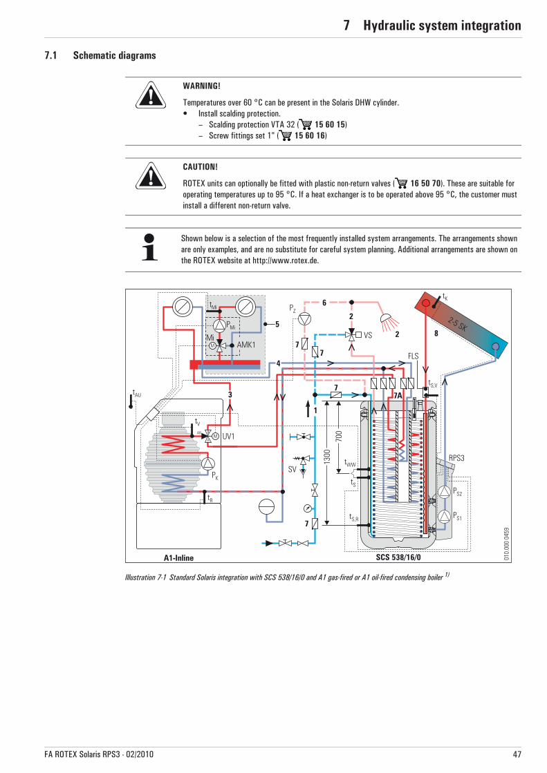
7 x Hydraulic system integration
47FA ROTEX Solaris RPS3 - 02/2010
7 Hydraulic system integration7.1 Schematic diagrams
WARNING!
Temperatures over 60 °C can be present in the Solaris DHW cylinder.• Install scalding protection.
– Scalding protection VTA 32 ( 15 60 15)– Screw fittings set 1" ( 15 60 16)
CAUTION!
ROTEX units can optionally be fitted with plastic non-return valves ( 16 50 70). These are suitable for operating temperatures up to 95 °C. If a heat exchanger is to be operated above 95 °C, the customer must install a different non-return valve.
Shown below is a selection of the most frequently installed system arrangements. The arrangements shown are only examples, and are no substitute for careful system planning. Additional arrangements are shown on the ROTEX website at http://www.rotex.de.
Illustration 7-1 Standard Solaris integration with SCS 538/16/0 and A1 gas-fired or A1 oil-fired condensing boiler 1)
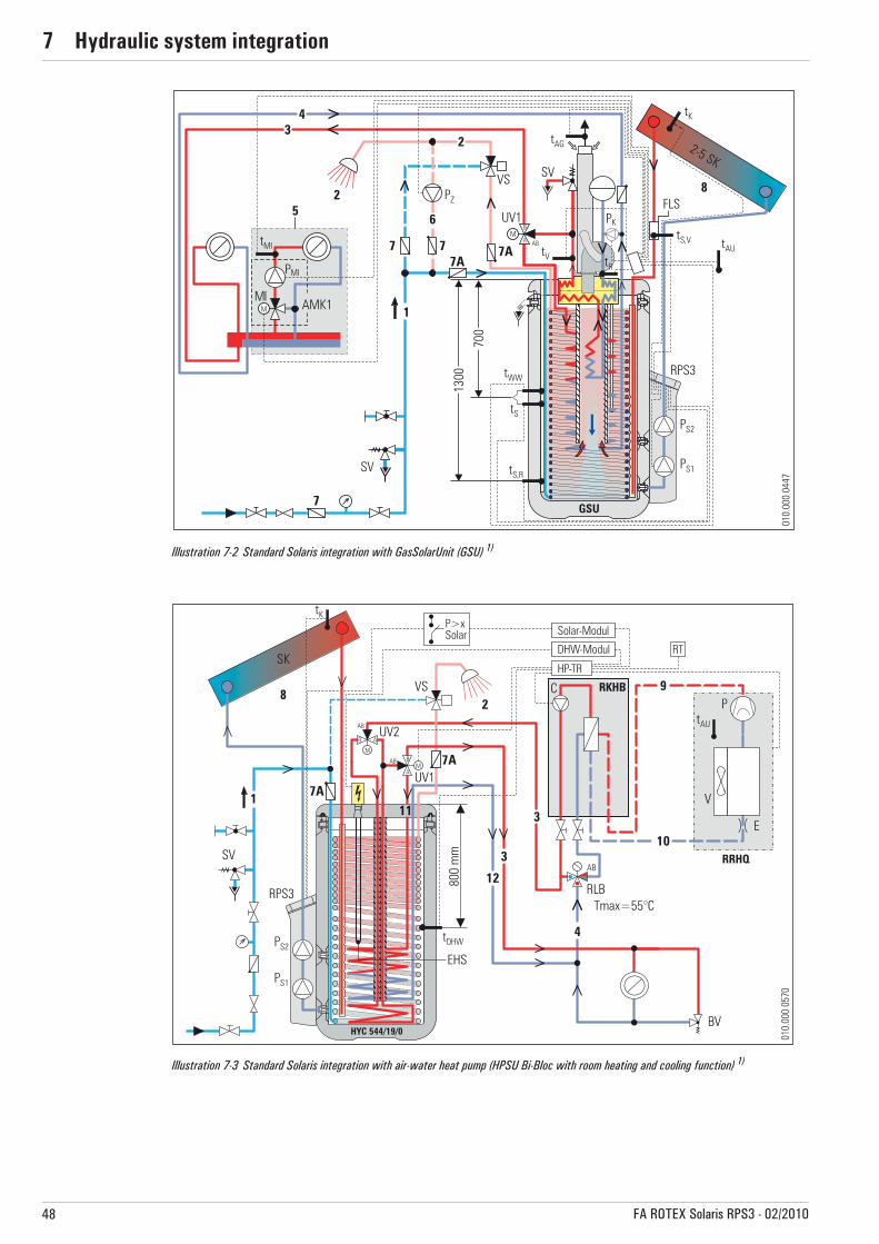
7 x Hydraulic system integration
48 FA ROTEX Solaris RPS3 - 02/2010
Illustration 7-2 Standard Solaris integration with GasSolarUnit (GSU) 1)
Illustration 7-3 Standard Solaris integration with air-water heat pump (HPSU Bi-Bloc with room heating and cooling function) 1)

7 x Hydraulic system integration
49FA ROTEX Solaris RPS3 - 02/2010
1) The system schematics shown make no claims to completeness and are no replacement for careful system planning.
Illustration 7-4 Solaris integration when using several Solaris storage tanks (SCS) (large installations) 1)

7 x Hydraulic system integration
50 FA ROTEX Solaris RPS3 - 02/2010
7.2 Short names
Short name Meaning Remark Order No.SCS 328/14/0 Sanicube Solaris INOX 16 50 10-49SCS 538/16/0 Sanicube Solaris INOX 16 45 16-49SCS 538/16/16 Sanicube Solaris INOX 16 45 17-49SCS 538/0/0 Sanicube Solaris INOX 16 45 15-49HYC 343/19/0 HybridCube 14 05 07HYC 544/19/0 HybridCube 14 05 01HYC 544/32/0 HybridCube 14 05 02
GSU S GasSolarUnit with solar heating support
GSU 520S-e 15 71 11-49GSU 520S F-e 15 71 12-49GSU 530S-e 15 71 22-49GSU 530S F-e 15 71 24-49
GSU GasSolarUnit without solar heating supportGSU 320-e 15 70 28-49GSU 320 F-e 15 70 29-49
A1-Inline A1 BO 15 bio-e 15 49 17-49A1 BO 20 bio-e 15 49 18-49A1 BO 27 bio-e 15 49 19-49A1 BO 35 bio-e 15 49 20-49A1 BG 25-e 15 59 00-49A1 BG 40-e 15 59 01-49
1 Cold water2 Hot water3 Heating inflow4 Heating return flow5 Mixer circuit Optional6 Circulation Optional7 Check valve, return valve on site7a Non-return valve (for cylinder connections) Accessories 16 50 708 Solar circuit9 Fluid pipe for coolant circuit for HPSU Bi-Bloc heat pump10 Gas pipe for coolant circuit for HPSU Bi-Bloc heat pump11 Cylinder flow12 Cylinder returnUV1 3-way diverter valveUV2 3-way diverter valve Accessories 15 60 34AMK1 Mixer group Accessories 15 60 44BV Overflow valve on siteC Circulation pump for inside unit for HPSU Bi-Bloc heat pump
FLSFlow sensor, Solaris FlowSensor FLS20 or alternative type according to Table 5-1 (Flow rate and flow temperature measurement) Accessories
16 41 07
FLG Solaris FlowGuard regulating valve with flow indicator 16 41 02HP-TR Main controller for HPSU heat pump Supplied with HPSU.Mi 3-way-mixer with drive motor Supplied with AMK1.PMi Mixer circuit pump Supplied with AMK1.PK Boiler circuit pump Supplied with GSU/A1-Inline.
PSSCylinder charging pump (only if there are several storage tanks intercon-nected)
on site
PZ Circulation pump on sitePS1 Circulation pump Supplied with RPS3.PS2 Booster pump Supplied with RPS3.RPS3 Regulation and pump unit Solaris Accessories 16 41 06-49RLB Return temperature limiter on siteRKHB Inside unit for HPSU Bi-Bloc heat pump
Supplied with HPSU heat pump.RRHQ Outside unit for HPSU Bi-Bloc heat pumpRT Room thermostat Accessories 14 10 03
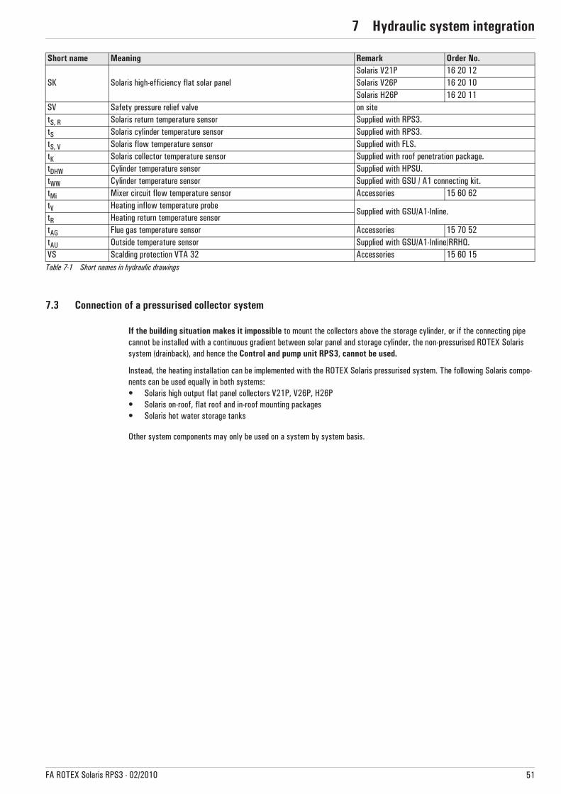
7 x Hydraulic system integration
51FA ROTEX Solaris RPS3 - 02/2010
Table 7-1 Short names in hydraulic drawings
7.3 Connection of a pressurised collector system
If the building situation makes it impossible to mount the collectors above the storage cylinder, or if the connecting pipe cannot be installed with a continuous gradient between solar panel and storage cylinder, the non-pressurised ROTEX Solaris system (drainback), and hence the Control and pump unit RPS3, cannot be used.
Instead, the heating installation can be implemented with the ROTEX Solaris pressurised system. The following Solaris compo-nents can be used equally in both systems:• Solaris high output flat panel collectors V21P, V26P, H26P• Solaris on-roof, flat roof and in-roof mounting packages• Solaris hot water storage tanks
Other system components may only be used on a system by system basis.
SK Solaris high-efficiency flat solar panelSolaris V21P 16 20 12Solaris V26P 16 20 10Solaris H26P 16 20 11
SV Safety pressure relief valve on sitetS, R Solaris return temperature sensor Supplied with RPS3.tS Solaris cylinder temperature sensor Supplied with RPS3.tS, V Solaris flow temperature sensor Supplied with FLS.tK Solaris collector temperature sensor Supplied with roof penetration package.tDHW Cylinder temperature sensor Supplied with HPSU.tWW Cylinder temperature sensor Supplied with GSU / A1 connecting kit.tMi Mixer circuit flow temperature sensor Accessories 15 60 62tV Heating inflow temperature probe
Supplied with GSU/A1-Inline.tR Heating return temperature sensortAG Flue gas temperature sensor Accessories 15 70 52tAU Outside temperature sensor Supplied with GSU/A1-Inline/RRHQ.VS Scalding protection VTA 32 Accessories 15 60 15
Short name Meaning Remark Order No.

8 x Technical data
52 FA ROTEX Solaris RPS3 - 02/2010
8 Technical data
8.1 Control and pump unit RPS3
8.2 Sensor characteristics
Control and pump unit RPS3
Dimensions W x H x D 230 x 815 x 142 mm
Operating voltage 230 V / 50 Hz
Circulation pump Grundfos UPSO 15-65 CIL2
Booster pump Grundfos UPS 15-65 CACAO
Max. electrical power consumption of RPS3At start: 240 W
In normal operation: 20-120 W (modulated)
Solaris R3 controller Digital differential temperature controller with plain text display
Max. electric power consumption of the control unit 2 W
Collector temperature sensor Pt 1000
Storage cylinder and return flow temperature sensor PTC
Flow temperature and flow rate sensor FLS20 (alternatively FLS12, FLS40, FLS100)
Table 8 -1 Technical data for Control and pump unit
Temperature sensorsSolaris sensor Sensor type Measured temperature in °C
-20 -10 0 10 20 30 40 50 60 70 80 90 100 110 120Sensor resistance in Ohm according to standard or manufacturer's indications
TR, TS PTC 1386 1495 1630 1772 1922 2080 2245 2418 2598 2786 2982 3185 3396TK Pt 1000 922 961 1000 1039 1077 1116 1155 1194 1232 1270 1308 1347 1385 1423 1461FlowSensor Sensor output voltage in VTV (0.5 - 3.5 V) 0.5 0.80 1.10 1.40 1.70 2.00 2.30 2.60 2.90 3.20 3.50Flow rate
FlowSensorMeasured flow in l/min0.0 2.0 4.0 6.0 8.0 10.0 12.0 14.0 16.0 18.0 20.0Sensor output voltage in V
V (0.36 - 3.5 V) 0.36 0.67 0.99 1.30 1.62 1.93 2.24 2.56 2.87 3.19 3.50
Table 8 -2 Table of the Solaris sensors
RS Sensor resistance (PTC, Pt 1000) t Temperature
Illustration 8-1 Resistance characteristics of the Solaris sensors

8 x Technical data
53FA ROTEX Solaris RPS3 - 02/2010
8.3 Terminal assignment of the RPS3 controller
L Flow rateU Sensor output voltage
t Temperature
Illustration 8-2 Characteristics of the FlowSensor
CONF Programming socket for software update
FLS Flow sensorTS Storage cylinder temperature sensor
TR Return flow temperaturesensor
TK Collector temperature sensor
BSK Burner inhibit contact
P1/P2 Circulation and Booster pump
F1 FusePower Mains supply
Illustration 8-3 Terminal assignment
Technical data for ROTEX condensing boilers, heat pumps and hot water storage tanks can be found in the ROTEX price list and the corresponding technical documentation for the products.

List of keywords9
54 FA ROTEX Solaris RPS3 - 02/2010
9 List of keywordsAAnti-freeze function . . . . . . . . . . . . . . . . . . . . . . . . . . . . . . . . 28, 32
BBooster temperature . . . . . . . . . . . . . . . . . . . . . . . . . . . .28, 31, 39Brief description . . . . . . . . . . . . . . . . . . . . . . . . . . . . . . . . . . . . . . . 8Burner inhibit contact . . . . . . . . . . . . . . . . . . . . . . . . . . . . . . . 37, 41
CCommissioning
With FlowSensor . . . . . . . . . . . . . . . . . . . . . . . . . . . . . . . . . . 22without FlowSensor . . . . . . . . . . . . . . . . . . . . . . . . . . . . . . . . 23
ControlBrief description . . . . . . . . . . . . . . . . . . . . . . . . . . . . . . . . . . . . 8
Control unitLanguage selection . . . . . . . . . . . . . . . . . . . . . . . . . . . . . . . . . 36Manual operation . . . . . . . . . . . . . . . . . . . . . . . . . . . . . . . . . . 29Password protection . . . . . . . . . . . . . . . . . . . . . . . . . . . . . . . . 36
Cylinder extension . . . . . . . . . . . . . . . . . . . . . . . . . . . . . . . . . . . . 19Cylinder extension kit . . . . . . . . . . . . . . . . . . . . . . . . . . . . . . . . . . 10Cylinder temperature sensor . . . . . . . . . . . . . . . . . . . . . . . . . . . . . 17
DDanger of frost . . . . . . . . . . . . . . . . . . . . . . . . . . . . . . . . . . . . . . . 25Decommissioning . . . . . . . . . . . . . . . . . . . . . . . . . . . . . . . . . . . . . 25
Permanent . . . . . . . . . . . . . . . . . . . . . . . . . . . . . . . . . . . . . . . 25Display during operation . . . . . . . . . . . . . . . . . . . .30, 32, 34, 36, 37Display during start-up . . . . . . . . . . . . . . . . . . . . . . . . . . . . . . . . . 33Disposal . . . . . . . . . . . . . . . . . . . . . . . . . . . . . . . . . . . . . . . . . . . . 26Drilling template . . . . . . . . . . . . . . . . . . . . . . . . . . . . . . . . . . . . . . 13
EElectric heater . . . . . . . . . . . . . . . . . . . . . . . . . . . . . . . . . . . . . . . 41Equalising pipe . . . . . . . . . . . . . . . . . . . . . . . . . . . . . . . . . . . . . . . 10Equalising pipe extension kit . . . . . . . . . . . . . . . . . . . . . . . . . . . . . 10Events memory . . . . . . . . . . . . . . . . . . . . . . . . . . . . . .32, 36, 43, 44
FFault codes . . . . . . . . . . . . . . . . . . . . . . . . . . . . . . . . . . . . . . . . . . 43Filling time . . . . . . . . . . . . . . . . . . . . . . . . . . . . . . . . . . . .22, 24, 28Flow
measurement . . . . . . . . . . . . . . . . . . . 7, 16, 22, 24, 29, 34, 40Quantity . . . . . . . . . . . . . . . . . . . . . . . . . . . . . . . .24, 30, 40, 45Setting . . . . . . . . . . . . . . . . . . . . . . . . . . . . . . . . .16, 20, 23, 24
FlowGuard . . . . . . . . . . . . . . . . . . . . . . . . . . . . . . .9, 16, 19, 40, 50FlowSensor . . . . . . . . . . . . . . . 7, 9, 16, 19, 29, 33, 39, 40, 50, 52
HHeat yield . . . . . . . . . . . . . . . . . . . . . . . . . . . . . . . . . . . . . . . . 30, 40
Day . . . . . . . . . . . . . . . . . . . . . . . . . . . . . . . . . . . . . . . . . . . . . 33Instantaneous output . . . . . . . . . . . . . . . . . . . . . . . . . . . . . . . 33Total . . . . . . . . . . . . . . . . . . . . . . . . . . . . . . . . . . . . . .32, 33, 36
Hot water storage tankCombining . . . . . . . . . . . . . . . . . . . . . . . . . . . . . . . . . .10, 19, 49Technical data . . . . . . . . . . . . . . . . . . . . . . . . . . . . . . . . . . . . 52Usable models . . . . . . . . . . . . . . . . . . . . . . . . . . . . . . . . . . . . . . 8
Hydraulic diagrams . . . . . . . . . . . . . . . . . . . . . . . . . . . . . . . . . . . . 47I
Info parameters . . . . . . . . . . . . . . . . . . . . . . . . . . . . .32, 33, 34, 36Inhibit time . . . . . . . . . . . . . . . . . . . . . . . . . . . . . . . . . . . .28, 39, 45Installation
Control . . . . . . . . . . . . . . . . . . . . . . . . . . . . . . . . . . . . . . . . . . 18Cylinder extension . . . . . . . . . . . . . . . . . . . . . . . . . . . . . . . . . 20FlowGuard . . . . . . . . . . . . . . . . . . . . . . . . . . . . . . . . . . . . . . . 16FlowSensor . . . . . . . . . . . . . . . . . . . . . . . . . . . . . . . . . . . . . . . 16
Pump unit . . . . . . . . . . . . . . . . . . . . . . . . . . . . . . . . . . . . . . . . 14Temperature sensor . . . . . . . . . . . . . . . . . . . . . . . . . . . . . . . . 17
Instantaneous output . . . . . . . . . . . . . . . . . . . . . . . . . . . . . . . . . . 33L
Language selection . . . . . . . . . . . . . . . . . . . . . . . . . . . . . . . . . . . . 36Large installations . . . . . . . . . . . . . . . . . . . . . . . . . . . . . . . . . . . . 49
MMalfunctions
Display of events . . . . . . . . . . . . . . . . . . . . . . . . . . . . . . . . . . 43Rectification . . . . . . . . . . . . . . . . . . . . . . . . . . . . . . . . . . . . . . 44
Manual operation . . . . . . . . . . . . . . . . . . . . . . . . . . . . . . . . . . . . . 29Minimum pump output . . . . . . . . . . . . . . . . . . . . . . . . . . . . . . . . . 30Mode of operation . . . . . . . . . . . . . . . . . . . . . . . . . . . . . . . . . . . . . 8
NNoise problems . . . . . . . . . . . . . . . . . . . . . . . . . . . . . . . . . . . . . . . 37
PParameter
Auxiliary heating via external heat sources . . . . . . . . . . . . . . . 41Heating by external heat sources . . . . . . . . . . . . . . . . . . . . . . 41Overview . . . . . . . . . . . . . . . . . . . . . . . . . . . . . . . . . . . . . . . . 39Recommended adjustment ranges . . . . . . . . . . . . . . . . . . . . . . 39
Password protection . . . . . . . . . . . . . . . . . . . . . . . . . . . . . . . . . . . 36Peak output . . . . . . . . . . . . . . . . . . . . . . . . . . . . . . . . . . . . . . . . . 33Pressurised collector system . . . . . . . . . . . . . . . . . . . . . . . . . . . . 51Product description . . . . . . . . . . . . . . . . . . . . . . . . . . . . . . . . . . . . . 7Pump modulation . . . . . . . . . . . . . . . . . . . . . . . . 16, 23, 30, 37, 41Pump output stages . . . . . . . . . . . . . . . . . . . . . . . . . . . . .30, 31, 32
RReset . . . . . . . . . . . . . . . . . . . . . . . . . . . . . . . . . . . . .32, 36, 37, 43Restart protection temperature . . . . . . . . . . . . . . . . . . . . . . . . . . . 28RPS3 control and pump unit . . . . . . . . . . . . . . . . . . . . . . . . . . . . . . 9
Components . . . . . . . . . . . . . . . . . . . . . . . . . . . . . . . . . . . . . . . 9Installation . . . . . . . . . . . . . . . . . . . . . . . . . . . . . . . . . . . . . . . 13
SSelf test . . . . . . . . . . . . . . . . . . . . . . . . . . . . . . . . . . . . . .32, 33, 34Setup menu . . . . . . . . . . . . . . . . . . . . . . . . . . . . . . . . . . .32, 34, 35
Fast access . . . . . . . . . . . . . . . . . . . . . . . . . . . . . . . . . . . . . . . 36Shutdown . . . . . . . . . . . . . . . . . . . . . . . . . . . . . . . . . . . . . . . . . . . 25
Temporary . . . . . . . . . . . . . . . . . . . . . . . . . . . . . . . . . . . . . . . 25Solaris storage cylinder extension kit . . . . . . . . . . . . . . . . . .10, 11Solaris system
Design . . . . . . . . . . . . . . . . . . . . . . . . . . . . . . . . . . . . . . . . . . . 7Speed control . . . . . . . . . . . . . . . . . . . . . . . . . . . . . . . . . . . . . . . . 30
Automatic . . . . . . . . . . . . . . . . . . . . . . . . . . . . . . . . . . . . . . . . 28Manual . . . . . . . . . . . . . . . . . . . . . . . . . . . . . . . . . . . . . . . . . . 37
Status column . . . . . . . . . . . . . . . . . . . . . . . . . . . . . . . . . . . .44, 45Status indication . . . . . . . . . . . . . . . . . . . . . . . . . . . . . . . . . .34, 43Switch-on inhibit temperature . . . . . . . . . . . . . . . . . . . . . . . . . . . . 44System concepts . . . . . . . . . . . . . . . . . . . . . . . . . . . . . . . . . . . . . 12
TTable of sensor faults . . . . . . . . . . . . . . . . . . . . . . . . . . . . . . . . . . 44Target temperature differential . . . . . . . . . . . . . . . . . . . . .30, 31, 33Technical data
Characteristics of the FlowSensor . . . . . . . . . . . . . . . . . . . . . 53RPS3 control and pump unit . . . . . . . . . . . . . . . . . . . . . . . . . . 52Temperature sensor . . . . . . . . . . . . . . . . . . . . . . . . . . . . . . . . 52
Technician reset . . . . . . . . . . . . . . . . . . . . . . . . . . . . . . . . . . . . . . 29Total heat yield . . . . . . . . . . . . . . . . . . . . . . . . . . . . . . . .32, 33, 36

10 x Notes
55FA ROTEX Solaris RPS3 - 02/2010
10 Notes

008.
1610
044_
01 ·
Erro
rs a
nd te
chni
cal c
hang
es e
xcep
ted
· Orig
inal
inst
ruct
ions
· 00
8.16
1004
9_01
· 02
/201
0 · i
n Ge
rman
· ©
ROTE
X
FA ROTEX Solaris RPS3 - 02/2010
x