rotex solaris rps3 p2 pressurised solar system€¦ · rotex solaris rps3 p2 ... the rotex solar...
TRANSCRIPT

For the qualified installer
SOLARIS R3P2
P1
TV
TS
TR
TK
-+
ok
007.16 011 49
Herstell-Nr.:A#:
Elektroheizstab6 kW
V = 500 l24 l93 kg593 kg
korrosionsbest‰ndig1,4 kWh
T = 85 ∞C
m ax
WarmwasserspeicherSanicubeSolaris INOX
Typ: SCS 538/16/16
Speichervolumen:
Trinkwasser-Nenninhalt:
Leergewicht:
Gesamtgewicht:
Korrosionsschutz:
Bereitschaftsw‰rmeaufwand
in 24 Stunden bei 60 ∞C
max. zul‰ssige
Speichertemperatur:max. zul‰
ssiger Betriebsdruck im
-Edelstahl-W‰rmetauscher:
Dauerleistung (DIN 4708):
Leistungskennzahl (DIN 4708):
(aber maximal Ladeleistung)
Speicher 65 ∞C, Kaltwasser 10 ∞C,
Warmwasser 45 ∞C, Ladeleistung 45 kW
-Zwischenmedium:
p = 10 bar
max
drucklos
QN = 45 kWN
= 2,8L
454297
454297XXXXXXXXX
164517-000
SanicubeSolaris
ROTEX Solaris RPS3 P2Pressurised solar system
Operating and installation manual
Valid for the following components
ROTEX Solaris unit version from 3.0
Solaris R3P differential temperature control system
Sanicube Solaris and HybridCube storage tank
Serial number
Customer
GBIssue 06/2012

2 FA ROTEX Solaris RPS3 P2 - 06/2012
Guarantee and conformity
Guarantee conditionsThe legal guarantee conditions fundamentally apply. Our warranty conditions beyond that can be found online on your sales presentative's webpage.
Declaration of conformity
for the Solaris RPS3 P2 pressurised solar system used in conjunction with pressure station RDS1.
We, ROTEX Heating Systems GmbH, declare under our sole responsibility that the products
Product Order No. Product Order No.
Solaris RPS3 P2 16 41 13 ROTEX RDS1 16 20 30
complies, in its standard design, with the following European Directives:
2004/108/EC Electromagnetic Compatibility 2006/95/EC EC Low Voltage Directive
Güglingen, 01.08.2009 Dr Eng. Franz GrammlingManaging Director

List of contents
3FA ROTEX Solaris RPS3 P2 - 06/2012
1 Safety . . . . . . . . . . . . . . . . . . . . . . . . . . . . . . . . . . . . . . . . . . . . . . . . . . . . . . . . . . . . . . . . . . . . . . . . . . . . . . . . . . . 51.1 Refer to the manual. . . . . . . . . . . . . . . . . . . . . . . . . . . . . . . . . . . . . . . . . . . . . . . . . . . . . . . . . . . . . . . . . . . . . . . . . . . . . . . . . . . . . . 51.2 Warning signs and explanation of symbols . . . . . . . . . . . . . . . . . . . . . . . . . . . . . . . . . . . . . . . . . . . . . . . . . . . . . . . . . . . . . . . . . . . . . 51.3 Avoid danger . . . . . . . . . . . . . . . . . . . . . . . . . . . . . . . . . . . . . . . . . . . . . . . . . . . . . . . . . . . . . . . . . . . . . . . . . . . . . . . . . . . . . . . . . . . 61.4 Intended use . . . . . . . . . . . . . . . . . . . . . . . . . . . . . . . . . . . . . . . . . . . . . . . . . . . . . . . . . . . . . . . . . . . . . . . . . . . . . . . . . . . . . . . . . . . 61.5 Instructions for working safely . . . . . . . . . . . . . . . . . . . . . . . . . . . . . . . . . . . . . . . . . . . . . . . . . . . . . . . . . . . . . . . . . . . . . . . . . . . . . 6
2 Product description. . . . . . . . . . . . . . . . . . . . . . . . . . . . . . . . . . . . . . . . . . . . . . . . . . . . . . . . . . . . . . . . . . . . . . . . . 72.1 Design and components of the solar system . . . . . . . . . . . . . . . . . . . . . . . . . . . . . . . . . . . . . . . . . . . . . . . . . . . . . . . . . . . . . . . . . . . 72.2 Brief description . . . . . . . . . . . . . . . . . . . . . . . . . . . . . . . . . . . . . . . . . . . . . . . . . . . . . . . . . . . . . . . . . . . . . . . . . . . . . . . . . . . . . . . . 82.3 System components . . . . . . . . . . . . . . . . . . . . . . . . . . . . . . . . . . . . . . . . . . . . . . . . . . . . . . . . . . . . . . . . . . . . . . . . . . . . . . . . . . . . . 82.4 Accessories. . . . . . . . . . . . . . . . . . . . . . . . . . . . . . . . . . . . . . . . . . . . . . . . . . . . . . . . . . . . . . . . . . . . . . . . . . . . . . . . . . . . . . . . . . . 10
3 Installation . . . . . . . . . . . . . . . . . . . . . . . . . . . . . . . . . . . . . . . . . . . . . . . . . . . . . . . . . . . . . . . . . . . . . . . . . . . . . . 113.1 System concepts. . . . . . . . . . . . . . . . . . . . . . . . . . . . . . . . . . . . . . . . . . . . . . . . . . . . . . . . . . . . . . . . . . . . . . . . . . . . . . . . . . . . . . . 113.2 Installing control and pump unit . . . . . . . . . . . . . . . . . . . . . . . . . . . . . . . . . . . . . . . . . . . . . . . . . . . . . . . . . . . . . . . . . . . . . . . . . . . . 113.3 Installing pressure station . . . . . . . . . . . . . . . . . . . . . . . . . . . . . . . . . . . . . . . . . . . . . . . . . . . . . . . . . . . . . . . . . . . . . . . . . . . . . . . . 143.4 Installing plate heat exchanger . . . . . . . . . . . . . . . . . . . . . . . . . . . . . . . . . . . . . . . . . . . . . . . . . . . . . . . . . . . . . . . . . . . . . . . . . . . . 153.5 Electrical connection . . . . . . . . . . . . . . . . . . . . . . . . . . . . . . . . . . . . . . . . . . . . . . . . . . . . . . . . . . . . . . . . . . . . . . . . . . . . . . . . . . . . 16
3.5.1 Solar panel circulation pump at RDS1 pressure station . . . . . . . . . . . . . . . . . . . . . . . . . . . . . . . . . . . . . . . . . . . . . . . . . . . . . . . 163.5.2 Solaris RPS3 P2 control and pump unit . . . . . . . . . . . . . . . . . . . . . . . . . . . . . . . . . . . . . . . . . . . . . . . . . . . . . . . . . . . . . . . . . . . 163.5.3 Installing temperature sensor . . . . . . . . . . . . . . . . . . . . . . . . . . . . . . . . . . . . . . . . . . . . . . . . . . . . . . . . . . . . . . . . . . . . . . . . . . 18
3.6 Accessories. . . . . . . . . . . . . . . . . . . . . . . . . . . . . . . . . . . . . . . . . . . . . . . . . . . . . . . . . . . . . . . . . . . . . . . . . . . . . . . . . . . . . . . . . . . 193.6.1 Installing FlowSensor . . . . . . . . . . . . . . . . . . . . . . . . . . . . . . . . . . . . . . . . . . . . . . . . . . . . . . . . . . . . . . . . . . . . . . . . . . . . . . . . 193.6.2 Installing FlowGuard . . . . . . . . . . . . . . . . . . . . . . . . . . . . . . . . . . . . . . . . . . . . . . . . . . . . . . . . . . . . . . . . . . . . . . . . . . . . . . . . . 203.6.3 Connecting multiple Sanicube hot water tanks . . . . . . . . . . . . . . . . . . . . . . . . . . . . . . . . . . . . . . . . . . . . . . . . . . . . . . . . . . . . . 20
4 Start-up and taking out of service . . . . . . . . . . . . . . . . . . . . . . . . . . . . . . . . . . . . . . . . . . . . . . . . . . . . . . . . . . . . 234.1 Initial start-up . . . . . . . . . . . . . . . . . . . . . . . . . . . . . . . . . . . . . . . . . . . . . . . . . . . . . . . . . . . . . . . . . . . . . . . . . . . . . . . . . . . . . . . . . 23
4.1.1 Fill solar panel circuit . . . . . . . . . . . . . . . . . . . . . . . . . . . . . . . . . . . . . . . . . . . . . . . . . . . . . . . . . . . . . . . . . . . . . . . . . . . . . . . . 234.1.2 Filling storage tank circuit (system without FlowSensor) . . . . . . . . . . . . . . . . . . . . . . . . . . . . . . . . . . . . . . . . . . . . . . . . . . . . . . 254.1.3 Filling storage tank circuit (system with FlowSensor) . . . . . . . . . . . . . . . . . . . . . . . . . . . . . . . . . . . . . . . . . . . . . . . . . . . . . . . . 26
4.2 Taking out of service. . . . . . . . . . . . . . . . . . . . . . . . . . . . . . . . . . . . . . . . . . . . . . . . . . . . . . . . . . . . . . . . . . . . . . . . . . . . . . . . . . . . 274.2.1 Temporary shutdown . . . . . . . . . . . . . . . . . . . . . . . . . . . . . . . . . . . . . . . . . . . . . . . . . . . . . . . . . . . . . . . . . . . . . . . . . . . . . . . . 274.2.2 Permanent decommissioning . . . . . . . . . . . . . . . . . . . . . . . . . . . . . . . . . . . . . . . . . . . . . . . . . . . . . . . . . . . . . . . . . . . . . . . . . . . 27
5 Operation . . . . . . . . . . . . . . . . . . . . . . . . . . . . . . . . . . . . . . . . . . . . . . . . . . . . . . . . . . . . . . . . . . . . . . . . . . . . . . . . 285.1 Operating and display components. . . . . . . . . . . . . . . . . . . . . . . . . . . . . . . . . . . . . . . . . . . . . . . . . . . . . . . . . . . . . . . . . . . . . . . . . . 285.2 Operation of control systems. . . . . . . . . . . . . . . . . . . . . . . . . . . . . . . . . . . . . . . . . . . . . . . . . . . . . . . . . . . . . . . . . . . . . . . . . . . . . . 28
5.2.1 Pump operation. . . . . . . . . . . . . . . . . . . . . . . . . . . . . . . . . . . . . . . . . . . . . . . . . . . . . . . . . . . . . . . . . . . . . . . . . . . . . . . . . . . . . 285.2.2 Switch-on lock-out function . . . . . . . . . . . . . . . . . . . . . . . . . . . . . . . . . . . . . . . . . . . . . . . . . . . . . . . . . . . . . . . . . . . . . . . . . . . 295.2.3 Manual operation . . . . . . . . . . . . . . . . . . . . . . . . . . . . . . . . . . . . . . . . . . . . . . . . . . . . . . . . . . . . . . . . . . . . . . . . . . . . . . . . . . . 305.2.4 Solaris FlowSensor . . . . . . . . . . . . . . . . . . . . . . . . . . . . . . . . . . . . . . . . . . . . . . . . . . . . . . . . . . . . . . . . . . . . . . . . . . . . . . . . . . 305.2.5 Output calculation, maximum values and yield count . . . . . . . . . . . . . . . . . . . . . . . . . . . . . . . . . . . . . . . . . . . . . . . . . . . . . . . . . 305.2.6 Speed control of the P1 tank circulation pump . . . . . . . . . . . . . . . . . . . . . . . . . . . . . . . . . . . . . . . . . . . . . . . . . . . . . . . . . . . . . 315.2.7 Global reset function. . . . . . . . . . . . . . . . . . . . . . . . . . . . . . . . . . . . . . . . . . . . . . . . . . . . . . . . . . . . . . . . . . . . . . . . . . . . . . . . . 325.2.8 Frost protection function . . . . . . . . . . . . . . . . . . . . . . . . . . . . . . . . . . . . . . . . . . . . . . . . . . . . . . . . . . . . . . . . . . . . . . . . . . . . . 325.2.9 Leak protection function . . . . . . . . . . . . . . . . . . . . . . . . . . . . . . . . . . . . . . . . . . . . . . . . . . . . . . . . . . . . . . . . . . . . . . . . . . . . . . 32
5.3 Setting and menu operation. . . . . . . . . . . . . . . . . . . . . . . . . . . . . . . . . . . . . . . . . . . . . . . . . . . . . . . . . . . . . . . . . . . . . . . . . . . . . . . 335.3.1 Start display . . . . . . . . . . . . . . . . . . . . . . . . . . . . . . . . . . . . . . . . . . . . . . . . . . . . . . . . . . . . . . . . . . . . . . . . . . . . . . . . . . . . . . . 345.3.2 Operating display . . . . . . . . . . . . . . . . . . . . . . . . . . . . . . . . . . . . . . . . . . . . . . . . . . . . . . . . . . . . . . . . . . . . . . . . . . . . . . . . . . . 345.3.3 Settings menu. . . . . . . . . . . . . . . . . . . . . . . . . . . . . . . . . . . . . . . . . . . . . . . . . . . . . . . . . . . . . . . . . . . . . . . . . . . . . . . . . . . . . . 345.3.4 Password input. . . . . . . . . . . . . . . . . . . . . . . . . . . . . . . . . . . . . . . . . . . . . . . . . . . . . . . . . . . . . . . . . . . . . . . . . . . . . . . . . . . . . 365.3.5 Language selection . . . . . . . . . . . . . . . . . . . . . . . . . . . . . . . . . . . . . . . . . . . . . . . . . . . . . . . . . . . . . . . . . . . . . . . . . . . . . . . . . . 365.3.6 Setting and resetting parameters . . . . . . . . . . . . . . . . . . . . . . . . . . . . . . . . . . . . . . . . . . . . . . . . . . . . . . . . . . . . . . . . . . . . . . . 365.3.7 Manual setting of pump speed control. . . . . . . . . . . . . . . . . . . . . . . . . . . . . . . . . . . . . . . . . . . . . . . . . . . . . . . . . . . . . . . . . . . . 365.3.8 Correction values for measuring points . . . . . . . . . . . . . . . . . . . . . . . . . . . . . . . . . . . . . . . . . . . . . . . . . . . . . . . . . . . . . . . . . . . 375.3.9 Burner inhibit contact . . . . . . . . . . . . . . . . . . . . . . . . . . . . . . . . . . . . . . . . . . . . . . . . . . . . . . . . . . . . . . . . . . . . . . . . . . . . . . . . 37

List of contents
4 FA ROTEX Solaris RPS3 P2 - 06/2012
5.4 Recommended settings. . . . . . . . . . . . . . . . . . . . . . . . . . . . . . . . . . . . . . . . . . . . . . . . . . . . . . . . . . . . . . . . . . . . . . . . . . . . . . . . . . . 385.4.1 Standard parameter settings, recommended setting ranges . . . . . . . . . . . . . . . . . . . . . . . . . . . . . . . . . . . . . . . . . . . . . . . . . . . . 385.4.2 Additional settings for your solar system . . . . . . . . . . . . . . . . . . . . . . . . . . . . . . . . . . . . . . . . . . . . . . . . . . . . . . . . . . . . . . . . . . 395.4.3 Recommended setting for supplementary heating with external heat sources or the electric immersion heater,
burner inhibit contact. . . . . . . . . . . . . . . . . . . . . . . . . . . . . . . . . . . . . . . . . . . . . . . . . . . . . . . . . . . . . . . . . . . . . . . . . . . . . . . . . 405.4.4 Tips for optimised user behaviour. . . . . . . . . . . . . . . . . . . . . . . . . . . . . . . . . . . . . . . . . . . . . . . . . . . . . . . . . . . . . . . . . . . . . . . . 415.4.5 Domestic water hygiene. . . . . . . . . . . . . . . . . . . . . . . . . . . . . . . . . . . . . . . . . . . . . . . . . . . . . . . . . . . . . . . . . . . . . . . . . . . . . . . 41
6 Faults and malfunctions. . . . . . . . . . . . . . . . . . . . . . . . . . . . . . . . . . . . . . . . . . . . . . . . . . . . . . . . . . . . . . . . . . . . 426.1 Display of events . . . . . . . . . . . . . . . . . . . . . . . . . . . . . . . . . . . . . . . . . . . . . . . . . . . . . . . . . . . . . . . . . . . . . . . . . . . . . . . . . . . . . . . 426.2 Troubleshooting . . . . . . . . . . . . . . . . . . . . . . . . . . . . . . . . . . . . . . . . . . . . . . . . . . . . . . . . . . . . . . . . . . . . . . . . . . . . . . . . . . . . . . . . 43
7 Hydraulic system connection. . . . . . . . . . . . . . . . . . . . . . . . . . . . . . . . . . . . . . . . . . . . . . . . . . . . . . . . . . . . . . . . 45
8 Technical data. . . . . . . . . . . . . . . . . . . . . . . . . . . . . . . . . . . . . . . . . . . . . . . . . . . . . . . . . . . . . . . . . . . . . . . . . . . . 498.1 Basic data . . . . . . . . . . . . . . . . . . . . . . . . . . . . . . . . . . . . . . . . . . . . . . . . . . . . . . . . . . . . . . . . . . . . . . . . . . . . . . . . . . . . . . . . . . . . 498.2 Diagrams . . . . . . . . . . . . . . . . . . . . . . . . . . . . . . . . . . . . . . . . . . . . . . . . . . . . . . . . . . . . . . . . . . . . . . . . . . . . . . . . . . . . . . . . . . . . . 50
9 List of keywords . . . . . . . . . . . . . . . . . . . . . . . . . . . . . . . . . . . . . . . . . . . . . . . . . . . . . . . . . . . . . . . . . . . . . . . . . . 51

1 x Safety
5FA ROTEX Solaris RPS3 P2 - 06/2012
1 Safety1.1 Refer to the manual
This manual is intended for authorised and trained technicians who have experience of the proper installation and commissioning of heating systems on account of their technical training and knowledge.
All activities required for installation, commissioning, operation, and adjustment of the heating system are described in this manual. For detailed information on the equipment connected to your heating system, please refer to the corresponding manuals.
Please read this manual carefully and thoroughly before proceeding with the installation and initial start-up or modification of the system.
Relevant documentsThe documents listed below are a part of the technical documentation of the ROTEX solar system and must also be taken into consideration. The documents are included in the scope of supply.– Domestic hot water storage tank (ROTEX Sanicube, HybridCube, GasSolarUnit): operating and installation instructions.– Solar panels: the installation instructions included for the applicable installation type.
When connecting to an external heat generator or storage tank which is not included in the scope of delivery, the individual associated operating and installation instructions apply.
1.2 Warning signs and explanation of symbols
Meaning of the warningsWarnings in this manual are classified according into their severity, the danger and the probability of occurrence.
Special warning signsSome types of danger are indicated by special warning signs.
Order numberNotes related to order numbers are identified by the shopping cart symbol .
DANGER!
Draws attention to imminent danger.
Disregarding this warning can lead to serious injury or death.
WARNING!
Indicates a potentially dangerous situation.
Disregarding this warning can result in serious injury or death.
CAUTION!
Indicates a situation which may cause possible damage.
Disregarding this warning may cause damage to property and the environment.
This symbol identifies user tips and particularly useful information, but not warnings or hazards.
Electrical current Danger of burning or scalding
Materials that are irritants or can damage your health
Risk of environmental damage

1 x Safety
6 FA ROTEX Solaris RPS3 P2 - 06/2012
Handling instructions• Handling instructions are shown as a list. Actions of which the sequential order must be maintained are numbered.
Results of actions are identified with an arrow.
1.3 Avoid danger
ROTEX solar systems are constructed to the state of the art and recognised laws of technology. However, improper use may result in serious physical injuries or death, as well as property damage. To avoid any danger, only install and operate your ROTEX solar system:– as stipulated and in perfect condition,– with an awareness of safety and the hazards involved.
This assumes knowledge and use of the contents of this manual, of the relevant accident prevention regulations as well as the recognised safety-related and occupational health rules.
1.4 Intended use
The ROTEX solar system may only be used for providing solar heating support to domestic hot water heating systems. The ROTEX solar system may only be installed, connected and operated in accordance with the specifications of this manual.
Any other use outside the above-mentioned use is considered as improper. Responsibility for any resulting damage will be borne by the user/owner alone.
Intended use also includes the observance of maintenance and inspection conditions. Replacement parts must at least satisfy the technical requirements defined by the manufacturer. This is the case, for example, with genuine spare parts.
1.5 Instructions for working safely
Working on the roof• Installation work on the roof may only be carried out by authorised and trained persons (heating technicians, roofers, etc.)
under observance of the relevant Accident Prevention Regulations.• Material and tools must be secured against falling.• Barriers must be erected to prevent persons from entering the area below the roof where the work is being carried out.• Observe safety clearances to overhead lines at the installation location.
Before working on the heating system• All work on the heating system (such as installation, connection and commissioning) may only be carried out by authorised
and trained heating technicians.• Switch off the main switch and secure it against unintended switching on when carrying out any work on the heating system.
Electrical installation• Electrical installation should only be carried out by qualified electrical engineers observing the technical electrical guidelines
and regulations of the relevant electric power supply company.• Before connecting to the mains supply, check that the voltage specified on the type label of the heating system
(230 V, 50 Hz) is the same as the available supply voltage.
Instruct the owner• Before you hand over the heating system, explain to the user/owner how to operate and check the heating system.
The ROTEX solar system can only be operated in conjunction with the RDS1 pressure system, the Solaris RPS3 P2 control and pump unit, the RPWT1 plate heat exchanger, and the installation materials intended for it.

2 x Product description
7FA ROTEX Solaris RPS3 P2 - 06/2012
2 Product description2.1 Design and components of the solar system
1 Cold water connection pipe2 Drinking water (hot) distributor3 Stainless steel corrugated heat exchanger for
domestic water (hot)4 Corrugated stainless steel pipe for heat exchanger
to heat generator (storage tank charging)5 Immersion sleeve for storage tank temperature
sensor6 Fill level display7 Filling and draining cock (customer)
(accessory 16 41 17)8 Differential temperature control9 Solar return line (bottom of the solar panel)10 Solar panel field11 Solar flow line (top of solar panel)12 Thermostatic mixer valve (consumer-side
scalding protection)
13 Gravity break*14 Solar flow layered pipe15 Corrugated stainless steel heat exchanger for
heating support16 Thermal insulation of stainless steel heat
exchanger for heating support17 Connection solar return flow18 Immersion sleeve for solar return flow
temperature sensor19 Safety overflow connection
I Double-sided connection for 2 to 5 solar panelsII Same-side connection for 2 or max. 3 solar
panels (not for inroof)
A Zone with water for domestic useB Solar zone
C Heating support zoneFLS20
Solaris FlowSensor (flow metering)*PS1 Tank circulation pumpPS2 Solar panel circulation pumpRDS1 Pressure stationRPS3 P2
Control and pump unitRPWT1
Plate heat exchangertK Solar panel temperature sensortV Solar flow temperature sensortS,R Solar return flow temperature sensortWW Domestic hot water temperature sensor
* Accessories
Fig. 2-1 Standard installation of a ROTEX solar system (ROTEX recommends the two-way connection)

2 x Product description
8 FA ROTEX Solaris RPS3 P2 - 06/2012
2.2 Brief description
The ROTEX solar system is a thermal system for generating hot water and heating support.
Mode of operationThe V21P, V26P and H26P high-performance flat solar panels convert the sun's radiation into heat with high efficiency. The heat-transfer medium in the solar panel system is a frost-proof water-glycol mixture, and tap water in the tank circulation system.
As soon as the solar panels have reached a useful temperature level, the liquid in the panel system is pumped through the pressure station and the plate heat exchanger. The feed pump of the Solaris RPS3 P2 control and pump simultaneously pumps the unpressurised buffer water in the domestic hot water storage tank through the plate heat exchanger where it absorbs the heat given off by the solar panel circuit.
Modular designThe system consists of several mainly pre-assembled modules. Plug-in technology and a high degree of pre-assembly ensure fast and simple installation.
Storage tankThe following can be used as storage tanks for the ROTEX solar system:– ROTEX Sanicube Solaris: Thermally insulated, non-pressurised plastic storage cylinder.– ROTEX Hybridcube: Thermally insulated, non-pressurised plastic storage cylinder.– ROTEX Gas Solar Unit (GSU): Sanicube Solaris with integrated gas condensing boiler.
Electronic controlThe fully-electronic control on the Solaris RPS3 P2 control and pump unit provides optimum utilisation of solar heat energy (hot water heating, heating support) and compliance with all operating safety aspects. All parameters needed for trouble-free operation have been preset at the factory.
2.3 System components
Control and pump unit RPS3 P2
Construction, operating principle, commissioning, and operation of the storage tank are not described in this manual. You will find detailed information on the storage tanks in their respective installation and operating manuals.
RPS3 P2 ( 16 41 13)
Consists of:– Cover– Connection piping with circulation pump– Control and pump unit RPS3 P2 with storage tank
temperature sensor, return flow temperature sensor, connection cable solar panel temperature sensor, connection cable 230 V mains (3 m)
– Accessory bag (4 fillister screws, 4 washers, 3 locking screws)
– Solaris documentation
Fig. 2-2 Control and pump unit RPS3 P2

2 x Product description
9FA ROTEX Solaris RPS3 P2 - 06/2012
RDS1 pressure station
RPWT1 plate heat exchanger
APWT1 connector kit for RPWT1 plate heat exchanger
RDS1 ( 16 20 30)
Pressure station including connection piping with Grundfos Solar 25-65 circulation pump, flowmeter with 2x KFE cocks, integrated air separator, safety group with pressure gauge, installation accessories.
Fig. 2-3 RDS1 pressure station
RPWT1 ( 16 20 31)
For connecting the RDS1 pressure station to an unpressurised hot water storage tank.
– Heat output 6 kW.– For pressurised solar systems with up to 5 solar panels.
Fig. 2-4 RPWT1 plate heat exchanger
APWT1 ( 16 20 32)
For hydraulic connection of the RPWT1 plate heat exchanger to the unpressurised tank circulation system of the hot water storage tank.
Consists of:– Connection fittings.– Insulated VA 15 solar / VA 18 solar-solar pipe.
Fig. 2-5 APWT1 connector kit

2 x Product description
10 FA ROTEX Solaris RPS3 P2 - 06/2012
2.4 Accessories
FLS20 FlowSensor
FLG FlowGuard
Diaphragm expansion vessel
Filling and draining cock (KFE) for Solaris RPS3 P2
FLS20 ( 16 41 02)
For measuring the flow volume and the feed temperature.
Consists of:– FLS20 FlowSensor.– 3 m cable (ready to plug in).– 2x seals.
Fig. 2-6 FLS20 FlowSensor supplied with 3 m cable
FLG ( 16 41 07)
For regulating the flow volume.
Consists of:– FLG FlowGuard.– 2x seals.
Fig. 2-7 FLG FlowGuard
MAG S 25 ( 16 20 50)
For ROTEX Solaris pressure systems with up to 3 solar panels.
– Diaphragm expansion vessel 25 l.– Cap valve, connector pipe, installation material.
MAG S 35 ( 16 20 51)
For ROTEX Solaris pressure systems with up to 5 solar panels.
– Diaphragm expansion vessel 35 l.– Cap valve, connector pipe, installation material.
Fig. 2-8 Diaphragm expansion vessel MAG S 25/35
16 41 17
Bild 2-9 KFE-cock
MAG 25 MAG 35

3 x Installation
11FA ROTEX Solaris RPS3 P2 - 06/2012
3 Installation3.1 System concepts
ROTEX solar systems are normally installed in accordance with the system concepts shown in the following. This also includes the possibility of connection on the opposite side of the flat solar panels in each case.
3.2 Installing control and pump unit
The high-output flat solar panels can be mounted on different types of roofs. For more information on installation of solar panels see:
– Pitched roof V21P/V26P/H26P: on-roof installation instructions for solar panels.– Flat roof V21P/V26P/H26P: installation instructions for the solar panel flat roof support frame.– In-roof V21P/V26P: in-roof solar panel installation instructions.
Connection at opposite ends possible1) (possible from 1+ solar panels) Same-side installation connection (up to maximum of 3 solar panels)
Fig. 3-1 Two-way connected solar panel field with Sanicube domestic hot water storage tank (1)ROTEX recommends this connection type)
Fig. 3-2 Solar panel with connections on same side with Sanicube hot water storage tank
WARNING!
Live parts can cause an electric shock on contact and cause fatal burns and injuries.• Before beginning maintenance work on the boiler control panel or the solar control system, disconnect
them from the power supply (switch off fuse, main switch) and secure against unintentional restart.• In order to avoid any danger caused by damaged electrical wiring, always have such wiring replaced by
electrical engineers in compliance with valid standards and guidelines as well as the specifications of the energy supply company.
• Comply with the relevant safety at work regulations.
The pump unit must be connected to the hot water storage tank before it is filled with water.
If the solar system is connected to a hot water storage tank that is already in operation, then the unpressurized storage tank section must first be drained.
For information about installing the control and pump unit Solaris RPS3 P2 to an older ROTEX domestic hot water storage tank, please get in touch with Rotex technical customer support.

3 x Installation
12 FA ROTEX Solaris RPS3 P2 - 06/2012
1. Remove the handle on the hot water storage tank and unscrew the sealing cap form the solar return connection.
2. Using the previously removed screws from the handle, screw the pump retainer bracket to the top holder of the handle fastener.
3. Place the pump and the storage tank connection nut on the respective storage tank mounting bracket and secure with retaining brackets.
4. If an optional combined filling and draining cock (KFE-cock 16 41 17) should be installed in the cylinder connecting bracket of the preassembled pump group (Image 3-5):
• Remove the retaining clip on the installation side (a).• Withdraw the blanking plug on the installation side.• Insert the combined filling and draining cock in the installation side and secure it with the retaining clip again.
5. Fit the preassembled pump unit on the storage tank mounting bracket using the seal provided and screw it to the solar return connection on the hot water storage tank. To make it easier to fit, the retainer can be clicked into the retainer bracket.
6. Tighten the storage tank connecting nut.
7. Screw the retainer to the retaining bracket (necessary to absorb the forces).
8. Screw the fixing bracket for the control system in position.
9. Install press-fit elbow (Ø 22/Ø 18 mm).
10. Prepare feed line (VA 15 Solar) with sensor cable and return line (VA 18 Solar). Cut open the twin heat insulation in the middle.
Fig. 3-3 Work step 1 Fig. 3-4 Work step 2 Fig. 3-5 Step 3, 4
Fig. 3-6 Work step 5 Fig. 3-7 Work step 6 Fig. 3-8 Work step 7

3 x Installation
13FA ROTEX Solaris RPS3 P2 - 06/2012
Fig. 3-9 Work step 8 Fig. 3-10 Work step 9 Fig. 3-11 Work step 10
11. Adapt the return line as required and lay separately after cutting the twin heat insulation.
12. Insert return line into the press-fitting on the pump outlet pipe.
Fig. 3-12 Work step 11 Fig. 3-13 Work step 12
CAUTION!
In the case of longer pipe runs with only a minimum gradient, it is possible for water pockets with a siphoning effect to develop due to thermal expansion of the plastic pipes between the mounting points:• The pipe should be fixed to a rigid structure (e.g. profile rail, pipe etc.).• Always make sure that pipe runs have a continuous gradient of at least 2 %.
3 x Installation
14 FA ROTEX Solaris RPS3 P2 - 06/2012
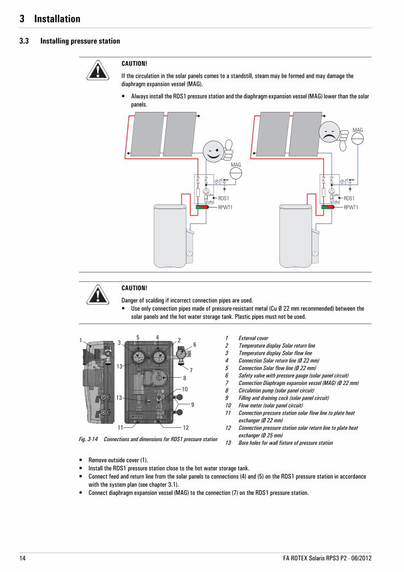
3.3 Installing pressure station
• Remove outside cover (1).• Install the RDS1 pressure station close to the hot water storage tank.• Connect feed and return line from the solar panels to connections (4) and (5) on the RDS1 pressure station in accordance
with the system plan (see chapter 3.1).• Connect diaphragm expansion vessel (MAG) to the connection (7) on the RDS1 pressure station.
CAUTION!
If the circulation in the solar panels comes to a standstill, steam may be formed and may damage the diaphragm expansion vessel (MAG).
• Always install the RDS1 pressure station and the diaphragm expansion vessel (MAG) lower than the solar panels.
CAUTION!
Danger of scalding if incorrect connection pipes are used.• Use only connection pipes made of pressure-resistant metal (Cu Ø 22 mm recommended) between the
solar panels and the hot water storage tank. Plastic pipes must not be used.
1 External cover2 Temperature display Solar return line3 Temperature display Solar flow line4 Connection Solar return line (Ø 22 mm)5 Connection Solar flow line (Ø 22 mm)6 Safety valve with pressure gauge (solar panel circuit)7 Connection Diaphragm expansion vessel (MAG) (Ø 22 mm)8 Circulation pump (solar panel circuit)9 Filling and draining cock (solar panel circuit)10 Flow meter (solar panel circuit)11 Connection pressure station solar flow line to plate heat
exchanger (Ø 22 mm)12 Connection pressure station solar return line to plate heat
exchanger (Ø 25 mm)13 Bore holes for wall fixture of pressure station
Fig. 3-14 Connections and dimensions for RDS1 pressure station

3 x Installation
15FA ROTEX Solaris RPS3 P2 - 06/2012
3.4 Installing plate heat exchanger
• Remove outside cover (1).• Install the RPWT1 plate heat exchanger under the RDS1 pressure station.• Connect feed and return line from RDS1 pressure station to connections (2) and (3) on the RPWT1 plate heat exchanger.• Flow and return line (VA 15 Solar / VA 18 Solar), install from Solaris RPS3 P2 control and pump unit and domestic hot water
storage tank to plate heat exchanger.• Connect the feed and return line (VA 15 Solar / VA 18 Solar) to the RPWT1 the APWT1 plate heat exchanger (connections 4
and 5) with the APWT1 plate heat exchanger connection set.• Replace outside cover (1).
Installing the clamping ring bolt:• Cut off the pipe end at right angles and debur.• Place swivel nut and clamping ring on the pipe.• Lightly oil threads.• Push pipe into the clamping ring bolt to the stop and tighten swivel nut by hand.• Tighten swivel nut with open-ended spanner.
1 External cover2 Connection pressure station solar return line (Ø 22 mm)3 Connection pressure station solar flow line (Ø 22 mm)4 Connection plate heat exchanger flow line to solar flow of
Solaris RPS3 P2 (Cu Ø 22 mm plug-in fitting)5 Connection plate heat exchanger return line to solar return flow
HybridCube (Cu Ø 22 mm plug-in fitting)6 Bore holes for wall fixture of plate heat exchanger
Fig. 3-15 Connections and dimensions for RPWT1 plate heat exchanger
Fig. 3-16 APWT1 connection set ( 16 20 32)

3 x Installation
16 FA ROTEX Solaris RPS3 P2 - 06/2012
3.5 Electrical connection
3.5.1 Solar panel circulation pump at RDS1 pressure station
3.5.2 Solaris RPS3 P2 control and pump unit
1. Fix the cable supplied to the back of the control system using the edge connectors. The plugs are coded to prevent mixing them up. The configuration of connections is shown on the lid of the control system.
2. All the cables are routed through the labyrinth to ensure there is stress relief.
3. Screw the 2-pin printed circuit board edge connector to the sensor line pulled in with the inflow and connect it to the control system.
1. Check the power supply voltage at the house junction box (~230 V, 50 Hz).
2. Disconnect the junction box of the domestic electrical installation.
3. Remove cover on switch casing of solar panel circulation pump.
4. Install control line from solar panel circulation pump to Solaris RPS3 P2 control and pump unit.
5. Connect control line to solar panel circulation pump.
– Follow the circuit diagram: image 3-17.
6. Install cover on switch casing of solar panel circulation pump.
7. Lay control line in casing of RDS1 pressure station.
8. Replace outside cover on RDS1 pressure station. Fig. 3-17 Electrical wiring of RDS1 circulation pump
Fig. 3-18 Work step 5 Fig. 3-19 Work step 6 Fig. 3-20 Work step 7
CONF Programming socket for software updateFLS FlowSensorTS Storage cylinder temperature sensor
TR Return flow temperature sensorTK Collector temperature sensorBSK Burner inhibit contact
P1/P2 Operation and booster pumpF1 FusePower Mains supply
Fig. 3-21 Connection assignment

3 x Installation
17FA ROTEX Solaris RPS3 P2 - 06/2012
4. Place the control system in the control system retaining brackets from above.
5. Connect the tank circulation pump to the control systems with the cable with the red mark.
6. Connect the control line coming from the solar panel circulation pump to the control systems with the unmarked cable.
7. Lay the cable for the control system along the return line and fix using cable ties.
8. Slide on casing front and align. Slide the casing front under the control system housing to form an even join all around the control systems.
9. Screw front of casing on both sides to the control systems housing with countersunk screws.
Fig. 3-22 Work step 1 Fig. 3-23 Work step 2 Fig. 3-24 Work step 3
Automatic speed control of the Solaris RPS3 P2 control and pump unit only works if a FlowSensor has been integrated into the system. Otherwise the tank circulation pump will operate at 100 %.
Fig. 3-25 Basic cabling: Storage tank, return flow, solar panel sensor, pump and mains lines
Fig. 3-26 Extended cabling additionally with FlowSensor
Fig. 3-27 Work step 4 Fig. 3-28 Work step 5(see also image 3-17)
Fig. 3-29 Work step 6(see also image 3-17)

3 x Installation
18 FA ROTEX Solaris RPS3 P2 - 06/2012
3.5.3 Installing temperature sensor
Fig. 3-30 Work step 7 Fig. 3-31 Work step 8 Fig. 3-32 Work step 9
10. Fasten housing front to the tank connection bracket below. To do this, carefully screw the self-tapping fixing screw (scope of supply) over the depression in the lower section of the front of the housing and then place the protective cap in position.
Fig. 3-33 Work step 10 Fig. 3-34 Assembled Solaris RPS3 P2
CAUTION!
The storage temperature sensor of the boiler control must never be immersed more than 75 cm into the sensor immersion sleeve. If the storage temperature sensor is immersed any deeper, the hot water zone may overheat and cause the boiler control to "stick" in the tank heating phase.
Fig. 3-35 Work step 1 Fig. 3-36 Work steps 2 + 3 Fig. 3-37 Work steps 2 + 3
1. Bend contact springs around the two sensors (tank and return sensor and also storage tank sensor of boiler control) and insert into the probe tube.
2. Align return flow sensor in the probe tube to approx. 130 cm insertion depth (cable ties).
3. Align storage tank sensor in the probe tube to approx. 70 cm insertion depth (cable ties).
4. Insert the plug in the probe tube and lay the cable.
Fig. 3-38 Work step 4

3 x Installation
19FA ROTEX Solaris RPS3 P2 - 06/2012
3.6 Accessories
3.6.1 Installing FlowSensor
The Solaris FlowSensor FLS20 (image 3-40, 16 41 07), available as an accessory, is a measurement instrument that records the flow volume in the solar panels and the feed temperature. The measurement range of the FlowSensor FLS20 is between 0 and 20 l/min (flow volume) and 0 to 120 °C (feed temperature). The measured values are shown in the display of the Solaris RPS3 P2 control and pump unit. Thanks to the speed control of the tank circulation pump, the Solaris RPS3 P2 control and pump unit automatically adjusts the passing flow during operation.
1. Place seal (b) on the solar flow connection (a) of the hot water storage tank.
2. Screw FlowSensor (c) to the solar flow connection (a) of the hot water storage tank.
3. Place seal (e) and install press fitting (f) on the outlet of the FlowSensors (c).
4. Insert prepared feed pipe (g) (Ø 15 mm) into the press fitting (f).
5. Lay the FlowSensor cable between the FlowSensor (c) and the control system.
6. Lay cable (i) from solar panel temperature sensor to the control systems.
7. Connect FlowSensor cable to FlowSensor (c) and to the control system printed circuit board edge at position FLS (4-pin, see image 3-21).
During installation be aware of the flow direction of the measurement instruments.
Fig. 3-39 Installing FlowSensor FLS Fig. 3-40 Accessories for FlowSensor FLS20 supplied with 3 m cable

3 x Installation
20 FA ROTEX Solaris RPS3 P2 - 06/2012
3.6.2 Installing FlowGuard
The Solaris FlowGuard FLG (image 3-41, 16 41 02) is also available as an accessory. It is a regulating valve with an integrated flow volume indicator that can be used to adjust the flow volume through the solar panels. The display range is between 2 and 16 l/min.
1. Place seal (b) on the solar flow connection (a) of the hot water storage tank.
2. Screw FlowGuard (d) to the solar flow connection (a) of the hot water storage tank.
3. Place seal (e) and install press fitting (f) on the outlet of the FlowGuard (c).
4. Insert prepared feed pipe (g) (Ø 22 mm) into the press fitting (f).
5. Lay cable (i) from solar panel temperature sensor to the control systems.
3.6.3 Connecting multiple Sanicube hot water tanks
The Solaris storage tank extension set is a system of Sanicube connection pipes that enable parallel connection of multiple Sanicube Solaris to form large systems with and without solar support.
The Solaris storage tank extension kit CON SX ( 16 01 07) allows 2 Sanicube Solaris to be connected for each Solaris RPS3 P2 control and pump unit (image 3-43).
Operation– The solar return flow from the RPWT1 plate heat exchanger comes from the solar zone of both storage tanks via the return
flow connection line (image 3-43, item 5).– Common return flow is pumped to the RPWT1 plate heat exchanger via the Solaris RPS3 P2 control and pump unit
(image 3-43, item 4).– The water is heated in the RPWT1 plate heat exchanger and flows as the solar inflow through the flow connection line
(two equally long insulated flexible pipes; item 6, image 3-43) into the two storage tanks.
Because the flow volume may differ during suction and inflow of the water circulating in the unpressurised circulation in spite of equalisation in the two Sanicubes by the two reducing valves (FLG), one of the two Sanicubes may overflow if there is a fault in a compensation line (image 3-43, item 5). This connection line prevents the level from rising excessively in one storage tank.
Fig. 3-41 Installing FlowGuard FLG Fig. 3-42 FlowGuard accessories
The optionally available ROTEX FlowGuard FLG ( 16 41 02) ensures that both Sanicubes are filled evenly. This requires installation of one FlowGuard per tank with a common inflow to the FlowSensor.
Observe the system for at least 2 h after connection and adjust the FlowGuard if necessary.

3 x Installation
21FA ROTEX Solaris RPS3 P2 - 06/2012
Installation
1. Installation of Solaris RPS3 P2 control and pump unit without attachment of the hood (see chapter 3.2).
2. Unscrew the cover cap of the solar return connection from the second storage tank.
3. Align Sanicube hot water storage tanks. The distance (centre tank) must be 830 mm. Note also the recommended wall distance of 200 mm.
4. Preparing the storage tank connecting angle to the Solaris RPS3 P2 control and pump unit. Do so by removing the retaining bracket on the expansion side and remove the ball cock or blanking plug, depending on previous installation.
5. Install the removed part on the return flow connection pre-installed by ROTEX on the 2nd storage tank connecting angle.
6. Insert the free press fitting (Ø 28) into the free outlet of the storage tank connection bracket on the completed return line on the side.
1 Sanicube Solaris2 Non-pressurised area3 Pressure area4 Solar panel5 Return flow connection pipe
(non-pressurised area)6 Solar flow distribution pipe7 Solar return pipe8 Solar flow pipe
DH Level difference in non-pressurised storage area
FLS20FlowSensor
FLG FlowGuardRDS1 Pressure stationRPWT1
Plate heat exchangerRPS3 P2
Control and pump unitSV Safety pressure relief valve
Fig. 3-43 Principle of the storage tank connection
WARNING!
Risk of scalding when removing the CON SX from the storage tank or when working on the hydraulics system of the Solaris RPS3 P2 control and pump unit (e.g. when replacing a pump).
• Drain storage tank before work on the connection line or hydraulic system.
CAUTION!
Large volumes of water may be drained from the Sanicube during installation.
• Install the Solaris storage tank extension set before filling the Sanicubes (unpressurised area).
CAUTION!
After extended storage, dirt may have accumulated on the seal of the return connection. This may result in water leaks, even with the check valve closed.
• Check the return connection for dirt and clean if necessary.• Check connection again for leaks at start-up.

3 x Installation
22 FA ROTEX Solaris RPS3 P2 - 06/2012
7. Fasten return line to the return connection on the second storage tank with the swivel nut. Place the flat gasket (included) in the swivel nut first.
8. Remove the bottom plug on the corresponding side of the cover.
9. Install cover on the storage tank.
10. Install solar flow connections with one FlowGuard each (optional) (see chapter 3.6.2).
11. Install the inflow connection pipes (left/right) on the connecting t-piece.
12. Position the flat gaskets on the two FlowGuards and fasten both FlowGuards to the inflow connection line with the swivel nut.
13. Position seal on the connecting t-piece and screw on the double swivel nut (1").
14. Position seal in double swivel nut (1").
15. Screw in FlowSensor in double swivel nut (1") (see chapter 3.6.1).
1 ROTEX SCS, GSU2 Solaris RPS3 P2 control and pump unit3 Solaris - flow manifold4 Connecting T-piece
AGL Compensation line ( 16 01 07)CON SX A
Storage tank extension set (bottom)CON SX B
Storage tank extension set (top)FLS20
FlowSensorFLG FlowGuard
Fig. 3-44 Installing the storage tank connection

4 x Start-up and taking out of service
23FA ROTEX Solaris RPS3 P2 - 06/2012
4 Start-up and taking out of service4.1 Initial start-up
4.1.1 Fill solar panel circuit
Table 4-1 Calculating pressures for start-up
1. Check that all threaded fasteners are tight.
2. Calculate the required initial pressure for the diaphragm expansion vessel (MAG) with the system unpressurised, check it and adjust if necessary (see MAG initial pressure tab. 4-1).
3. Open ball cock ball valves of feed and return flow at the RDS1 pressure station.
4. Set the blocking of the flow meter (item 10, image 3-14) to the filling position (slot horizontal).
WARNING!
The solar system cannot be started until all hydraulic and electrical connections have been completed.
Incorrect commissioning will impair the system's function, and can lead to damage to the entire installation. Therefore, installation and commissioning should only be carried out by heating technicians trained and authorised by ROTEX.
CAUTION!
Danger of scalding by hot solar fluid and escaping steam.
• Only fill the solar panel circuit when there is no strong direct sunlight or only if the solar panels are covered up.
WARNING!
If the heat transfer medium is mixed with other substances, frost and corrosion protection may be reduced. This may damage system components.
• Conduct all work on the components of the solar system only with the solar panels covered.• Only rinse and fill solar system with the prescribed heat exchanger fluid (e.g. ROTEX Solarfluid CORACON
SOL 5F, 16 20 52).• Mixing of the heat-transfer medium with other materials is not permitted. To extend frost-protection, use
a heat-transfer medium of the same value (e.g. ROTEX Solarfluid CORACON SOL 5, 16 20 53).
WARNING!
If heat transfer media containing glycol are exposed to temperatures above 170 °C over an extended period, they will decompose or form silt. This may reduce the frost protection, affect the output of the solar system and damage components of the system.
• Start operation of the solar system immediately after filling it.• Drain the system if it is to be out of operation over an extended period.• Replace the heat transfer medium in the system before start-up after extended downtime.
MAG initial pressure System fill pressure Maximum system pressure
pv = 0.1 x hstat + 0.5 bar p0 = pv + 0.3 bar pe <= 0.9 x psv
pe Maximum permissible system pressure (warm) in bar
psv Contact pressure of safety valve (>3 bar)
pv Prepressure MAG in bar ( at least 1.2 bar)
p0 System fill pressure (cold) in bar
hstat Static height in m between centre of MAG and highest system point

4 x Start-up and taking out of service
24 FA ROTEX Solaris RPS3 P2 - 06/2012
5. Connect filler/rinsing pump with hose on top filling and draining cock (see also item 9, image 3-14) to RDS1 pressure station.
6. Connect return flow hose to lower filling and draining cock (see also item 9, image 3-14) of RDS1 pressure station and guide into fill container, from which the ROTEX Solarfluid CORACON SOL 5F solar fluid is filled in the solar panel circuit.
7. Start filling and draining cock and filler/rinsing pump.
8. Fill and flush the solar panel circuit until the solar fluid flows back into the filling container cleanly and without any bubbles.
9. The pressure measured by the pressure gauge of the RDS1 pressure station must not exceed the maximum permissible system pressure pe (tab. 4-1).
10. Close lower filling and draining cock.
11. Increase the solar panel circuit pressure to at least 0.3 bar above the pressure set at the diaphragm expansion vessel (MAG) (see system fill pressure tab. 4-1).
12. Close upper filling and draining cock.
13. Vent the system as follows:
• Direct the venting hose of the venting pot into a suitable collection vessel.• Open valve (item 3, image 4-1) of the venting pot (item 1, image 4-1).
Displaced air escapes from the venting pot.
• Close the valve as soon as solar fluid comes out of the venting pot.
14. Check system pressure on pressure gauge of RDS1 pressure station again.
– The system pressure must not drop over a period of 1/2 hour.– If the pressure drops, check the solar panel circuit and connections for leaks and repair if necessary.– Vent solar panel circuit again (residual air in system).– If necessary, correct the system pressure by adding solar fluid (see working step 4 onwards).
15. Disconnect filler/rinsing pump with hoses from the RDS1 pressure station.
16. Open the blocking of the flow meter completely (slot vertical).
Fig. 4-1 Filling and venting the solar panel circuit
HYCSCS
RDS1
RPWT1
1
2
3

4 x Start-up and taking out of service
25FA ROTEX Solaris RPS3 P2 - 06/2012
4.1.2 Filling storage tank circuit (system without FlowSensor)
1. Filling the hot water storage tank:
• Fill the heat exchanger for domestic water.• Fill buffer storage volume via the filling and draining cock (accessory 16 41 17) on the Solaris RPS3 P2 control and
pump unit until the water starts flowing out of the safety overflow.• Close the filling and draining cock (accessory 16 41 17).
2. Switch on Solaris RPS3 P2 control and pump unit (initialisation phase begins).
3. After the initialisation phase (temperature display), vent the system by pressing the two arrow keys simultaneously (start manual operation).
The pump now operates at full power and the system is at the maximum possible operating pressure. The storage tank circuit fills, the air is vented through the feed line into the air space of the hot water storage tank. A bypass in the FlowGuard regulating valve ensures that the system is vented automatically, even if the valve is fully closed.
4. Close regulating valve completely. The system is now under the maximum possible operating pressure.
5. Check the entire system for leaky joints (in the building and on the roof). Any leaks must be eliminated properly.
6. Adjust flow depending on the number of solar panels. For reference values for the setting see tab. 4-2.
Table 4-2 Setting the flow at the FlowGuard (FLG)
7. Switch off Solaris RPS3 P2 control and pump unit.
8. Check the filling level in the hot water storage tank.
9. Only if the water level in the hot water storage tank is not close to the fill level:
• Switch on Solaris RPS3 P2 control and pump unit again (initialisation phase begins).• When the initialising phase is finished (temperature display), you can start the manual operating mode by simultaneously
pressing both arrow keys.• Measure the time until the inflow is heated at the plate heat exchanger.• Set the measured time plus 5 s in the parameter "Time PsE" (see chapter 5.3.6).
10. Switch Solaris RPS3 P2 control and pump unit to Automatic mode by pressing both arrow keys down at the same time or by performing another switch on/switch off. The system is now ready for operation.
11. Complete the thermal insulation at the connecting points.
12. Instruct the user, fill out the acceptance report, and send it to the address indicated on the rear cover of this manual.
The flow of the solar panel circuit can be checked at the flow display of the ROTEX RDS1 pressure station (settings see tab. 4-2).
If a heat meter is installed in the system, the flow can be set based on the heat meter reading (settings see tab. 4-2).
Number of collectors
Nominal flow in l/min
Desired flow in l/hour
Solar panel circuit Storage tank circuit Solar panel circuit Storage tank circuit
2 3.6 to 4.8 3.0 to 4.0 220 to 290 180 to 240
3 5.4 to 7.2 4.5 to 6.0 330 to 435 270 to 360
4 7.2 to 9.6 6.0 to 8.0 435 to 580 360 to 480
5 9 to 12 7.5 to 10.0 540 to 720 450 to 600
The pumps are only switched on if the temperature of the solar panels is higher than the minimum value coupled to the minimum temperature of the storage tank (see chapter 5.2.9) and lower than the specified approved maximum temperature.
If there is a longer period between step 5 and 7, the temperature of the solar panels may be outside the approved range. If TK > TKzul it is not necessary to switch to manual operation.

4 x Start-up and taking out of service
26 FA ROTEX Solaris RPS3 P2 - 06/2012
4.1.3 Filling storage tank circuit (system with FlowSensor)
1. Filling the hot water storage tank:
• Fill the heat exchanger for domestic water.• Fill buffer storage volume via the filling and draining cock (accessory 16 41 17) on the Solaris RPS3 P2 control and
pump unit until the water starts flowing out of the safety overflow.• Close the filling and draining cock (accessory 16 41 17).
2. Switch on Solaris RPS3 P2 control and pump unit (initialisation phase begins).
3. After completing the initialisation phase (temperature display) you must bleed the system by pressing the two arrow keys simultaneously (starting manual mode).
The pump now operates at full power and the system is at the maximum possible operating pressure. The storage tank circuit fills, the air is vented through the feed line into the air space of the hot water storage tank.
4. Check the entire system for leaky joints (in the building and on the roof). Repair any leaks found.
5. Switch off Solaris RPS3 P2 control and pump unit.
6. Check the filling level in the hot water storage tank.
7. Only if the water level in the hot water storage tank is not close to the fill level:
• Switch on Solaris RPS3 P2 control and pump unit again (initialisation phase begins).• When the initialising phase is finished (temperature display), you can start the manual operating mode by simultaneously
pressing both arrow keys.• Measure the time until the inflow is heated at the plate heat exchanger.• Set the measured time plus 5 s in the parameter "Time PsE" (see chapter 5.3.6).• Start manual operation again by pressing the two arrow keys simultaneously.• Measure the time during which the storage tank circuit is completely filled. The filling process is complete when no air
noise can be heard and a stable value for the flow is displayed (actuate "Flow" measuring point with arrow keys).
8. Switch Solaris RPS3 P2 control and pump unit to Automatic mode by pressing both arrow keys down at the same time or by performing another switch on/switch off. The system is now ready for operation.
9. Only when the Solaris RPS3 P2 control and pump unit is connected to two domestic hot water storage tanks via the connection cable (storage tank extension kit CON SX):
– The measured common flow in the solar inflow must be evenly distributed over both hot water storage tanks. We recommend using a FlowGuard on each hot water storage tank.
10. Instruct the user, fill out the acceptance report, and send it to the address indicated on the rear cover of this manual.
The flow of the solar panel circuit can be checked at the flow display of the ROTEX RDS1 pressure station (settings see tab. 4-2).
If a heat meter is installed in the system, the flow can be set based on the heat meter reading (settings see tab. 4-2).

4 x Start-up and taking out of service
27FA ROTEX Solaris RPS3 P2 - 06/2012
4.2 Taking out of service
4.2.1 Temporary shutdown
If solar support is not needed for the water heater for a longer period of time, the solar system can be switched off temporarily from the mains switch of the Solaris RPS3 P2 control and pump unit.
If there is any danger of frost in the area of the storage tank circuit do the following:– start the solar system in operation
or– suitable antifreeze measures must be applied to the connected heating system and hot water storage tank (e.g. draining).
Draindomestic hot water storage tank• Switch off the main switch and secure against restarting.• Connect the hose to the solar return flow of the hot water storage tank with the KFE cock (accessory 16 41 17) using
the hose connection. • Drain the tank's water content.
4.2.2 Permanent decommissioning
• Taking the Solaris RPS3 P2 control and pump unit out of service (see chapter 4.2.1 "Temporary shutdown").• Disconnect the Solaris RPS3 P2 control and pump unit from all electrical connections and hydraulic connections.• Uninstall the Solaris RPS3 P2 control and pump unit as shown in the installation instructions (chapter 3 "Installation") but
in the reverse order.• Dispose of the Solaris RPS3 P2 control and pump unit correctly.
Notes on disposal
CAUTION!
A heating system which is shut down can freeze in the event of frost and may suffer damage.• Drain the heating system that is shut down if there is danger of frost.
If there is a danger of frost for just a few days, the unit's excellent heat insulation means that the insulated tank does not have to be drained, provided that the storage tank temperature is monitored regularly and does not fall below +3 °C. This does not, however, provide any protection against frost for the connected heat distribution system!
Due to the environmentally-friendly design of the Solaris system, ROTEX has complied with the requirements for environmentally-responsible disposal. During the disposal process, the only waste accrued is that which can be used for material or thermal recycling.
The materials used that are suitable for recycling can be sorted into individual types.
The designation of the product means that electrical and electronic products may not be disposed of together with unsorted domestic waste.
Proper disposal in compliance with the respective national regulations of the country of use is the responsibility of the user/owner.• Disassembly of the system, handling of coolant, oil and other parts may only be carried out by a qualified
fitter.• Disposal may only be carried out by a facility that specialises in reuse, recycling and recovery.Further information is available from the installation company or the responsible local authorities.

5 x Operation
28 FA ROTEX Solaris RPS3 P2 - 06/2012
5 Operation5.1 Operating and display components
5.2 Operation of control systems
5.2.1 Pump operation
During pump operation:– Continuous measurement of the temperature difference between solar panels and return temperature and comparison
with selected parameter "Delta T on".– Pumps switched on if this parameter is exceeded (e.g. return temperature equal to 40 °C and "Delta T on" equal to 15 K;
solar panel temperature >55 °C).
If the FlowSensor measures a stable flow before expiry of this period, the solar system is in operating mode.
– With installed FlowSensor only: the pump control systems depending on the temperature difference between the Solaris feed and return temperature.
1 Main switch with indicator light2 Display for showing temperature and parameters
(energy saving function: display lighting switches off automatically 10 min after the last button press)
3 Light for collector temperature display4 Light for Solaris flow temperature and
(flow measurement indicator (FLS))5 Light for storage cylinder temperature display6 Light for solar return flow temperature display7 Operating status light for tank circulation pump
with speed control P1 (lit up when pump is in operation- blinks when pump is running in throttled state)
8 Operating status light for Solar panel circulation pump P2 (lit when pump is in operation)
9 Up arrow for moving the temperature or parameter display up by one setting/increasing parameter settings
10 Down arrow for moving the temperature or parameter display down by one setting/decreasing parameter settings
11 Information key for accessing the information level (displays measured values, maximum values and calculated values) and OK key for confirming and storing settings in the setting menu
12 Controller housing13 Housing locking screws (device may only be
opened by an authorised specialist. Disconnect power before opening.)
Fig. 5-1 Operating and display components for the R3P control systems
Due to continuous improvements for optimum use of the Solaris RPS3 P2 control and pump unit, the Solaris R3P control has been fitted with an update function. Therefore, some functions described in this chapter are applicable to specific software versions only. These functions are indicated separately by symbols.
Software updates to the Solaris R3P control may only be carried out by a ROTEX service technician.
The ROTEX solar system is operated fully-automatically throughout the year. The speed-controlled pump operation is controlled by the Solaris R3P control systems. The operating and display components are shown in image 5-1.
The power switch completely disconnects the Solaris R3P control systems from the mains voltage. Switching on the power switch requires greater pressure on the button than pressing the operating buttons.

5 x Operation
29FA ROTEX Solaris RPS3 P2 - 06/2012
The pumps are switch off when:– The temperature difference falls below the value set at parameter "Delta T off" (e.g. return temperature = 45 °C and
"Delta T off" = 2 K; Solaris feed temperature <47 °C).– If the maximum storage tank temperature set in parameter "TS max" is reached (TS indicator flashes). In this case the
pumps can only be started again if the storage tank temperature has fallen by more than 2 K.– If the maximum solar panel temperature set in parameter "Tk zul" is reached (Tk indicator flashes). In this case the pumps
can only be started again if the solar panel temperature has fallen by more than 2 K.
5.2.2 Switch-on lock-out function
The switch-on lock-out function prevents:– reactivation if the solar system has been automatically shutdown because the set maximum storage tank temperature
"TS max" has been reached.– pump operation if the solar panel temperature exceeds the value set by the heating expert with the parameter "TK zul". Under sustained solar radiation temperatures over 100 °C may occur at the solar panels after switching off the pumps. If the storage tank temperature falls below the release temperature ("TS max" – 2 K) in this situation (e.g. by removal of hot water), the pumps are switched on again when the cut-in switch protection temperature at the solar panels set with parameter "TK zul" falls by 2 K. The TK indicator flashes.
The lock-out time "Time SP" function allows the pumps to be released again in a shutdown condition caused by the feed sensor (FlowSensor) only after expiry of the lock-out time set in the Solaris R3P control system (0 – 600 s).
Therefore:– cycling of the system can be minimised.– the solar panels can reach a higher temperature.– the feed temperature during filling the system does not fall below the cut-out condition and the system regulates itself faster.
If a FlowSensor is not installed or is faulty, the P1 tank circulation pump runs constantly at the set output level (without speed control). The pumps are regulated exclusively by the temperature difference between the solar panel and Solaris return flow temperature.
TOFF Switch-on temperature differenceTON Switch-on temperature difference
PS1 Tank circulation pumpPS2 Solar panel circulation pumpt TimeTK Collector temperatureTR Return flow temperatureTV Flow temperatureZeitPsA Tank circulation pump cut-out delayZeitPsE Tank circulation pump cut-in delayZeitUB Reverse condition delay time
1 Tank circulation pump cut-in delay:For maximum use of the heat the solar panel circuit is started before circulating the storage tank circuit. The preheated plate heat exchanger can heat immediately with the time-offset start of the tank circulation pump.
2 Tank circulation pump cut-out delay:To prevent temperatures >100 °C in the plate heat exchanger after the solar panel circulation pump switches off, for the TimePsA set in the parameters.
Fig. 5-2 Start sequence for storage tank and solar panel circulation pump

5 x Operation
30 FA ROTEX Solaris RPS3 P2 - 06/2012
5.2.3 Manual operation
The system can started manually with the time set in the parameter "H/A" for start-up and testing only. All control functions are disabled and both pumps run continuously at the specified output independently of the system temperatures.
• Pressing (>1 s) both arrow keys simultaneously activates or deactivates manual operation.
5.2.4 Solaris FlowSensor
The optional Solaris FlowSensor is used to measure the flow "V" and the feed temperature "TV".If a sensor is connected and activated:– the measurement values "V" and "TV" are displayed.– the control systems operate after the filling process with the actual system temperature difference of feed and return
temperature.If the system has detected the FlowSensor once, a fault signal is shown if the sensor is faulty or disconnected (see section 6.1). The system now operates in emergency mode without a FlowSensor.
If the control systems detect a FlowSensor after a new installation or a reset by a technician, the value "20" in parameter "FLS active" is automatically set. It is only necessary to check and, if necessary, adjust the correct parameter value for the specific FlowSensor (see table 5-1). The Flow Sensor can be disabled by input of the parameter value "0".
If the FlowSensor is disabled by the heating expert, a fault signal is not shown. The control system now operates without the measured value for the flow. The feed temperature "TV" is set to be equal to the solar panel temperature "TK".
5.2.5 Output calculation, maximum values and yield count
If a Solaris FlowSensor is connected, the system operating data are calculated and balanced, such as the current heat output and the solar heat yield. The maximum and calculated values can be shown on the display (see chapter 5.3). Values greater than "0" that have not been deleted will continue to be displayed even after removal or deactivation of the FlowSensors (without further updates).
CAUTION!
Uncontrolled manual operation may cause vapour pressure pulses, heat loss, excessive storage tank tempera-tures and in extremely cold conditions frost damage.
To prevent vapour pressure pulses:• the solar panel temperature must be TK < TK zul. Manual operation is blocked if TK > TK zul and can only
be started after sufficient cooling of the solar panels.
FlowSensor Parameter value"FLS active"
Minimum flow start phase "V1" in l/min
Minimum flow operating phase "V2" in l/min
1.0 ( on request) 12 1.5 1.0
1.3 ( 16 41 07) 20* 2 1.5
2.0 ( on request) 40 5 2.5
5.0 ( 16 41 03) 100 10 5.5
Table 5-1 Overview of FlowSensors *automatically set value with detected FlowSensor
Balancing and calculating system operating data (e.g. solar heat yield) does not replace official calibration of the heat meter. The values must not be used for distribution of heat costs or similar official balances.

5 x Operation
31FA ROTEX Solaris RPS3 P2 - 06/2012
5.2.6 Speed control of the P1 tank circulation pump
After the start sequence the Solaris R3P control systems initiate the following:– Stepwise output reduction of P1 until the calculated nominal spread "DT" maintains the setpoint value corresponding to
image 5-3, or until it falls below the minimum flow V2 (image 5-4). – The switch to the next pump stage is implemented after a safety time "t2" (image 5-4).
If the pump output is too low, the flow in the solar panel circuit may be interrupted depending on the system or the temperature. If the flow falls below the value "V2" for at least 10 s (image 5-4), the control systems detect a flow interruption, and the last valid output stage is saved as the minimum pump output. Lower pump output stages are blocked.
The temperature-dependent output control of P1 is between the calculated minimum and maximum output. The spread of "TV"and "TR" is continuously measured and compared with the nominal spread. If the temperature spread between "TV" and "TR" is too great, the pump output of P1 (max. 10 stages) and therefore the flow through the solar panels is increased until the nominal spread is reached. If the spread is too low, the pump output is reduced. The actual pump output of P1 while it is running is displayed as a percentage in the "Flow" indicator beside the measured flow value. A typical operating sequence of a modulating solar system is shown in image 5-3.
Fig. 5-4 Example for modulation operation with flow-caused block of low pump stages on systems with FlowSensor
DT Set temperature difference (calculated for operating point)
S1 Upper set temperature difference ("temperature difference 1")
S1 Lower set temperature difference ("temperature difference 2")
TK Collector temperatureT1 Minimum temperature of storage tank ("TR min")T2 Booster temperature ("TK max")T3 Switch-on inhibit temperature ("TK zul")— Nominal spread--- Switching limits for pump modulation
Fig. 5-3 Temperature difference-dependent pump output control
A Start phaseB Operating phase (modulation)C Interrupted flowD Low pump output stages are automatically disabled
when flow is interruptedV Solar circuit flowV1 Minimum flow in start phase ("VS min")V2 Minimum flow in operating phase ("S flow")
t Timet1 Maximum start run time of tank
circulation pump ("Time PsE")t2 Stabilisation period ("S time")t3 Interruption detection period (10 s)

5 x Operation
32 FA ROTEX Solaris RPS3 P2 - 06/2012
5.2.7 Global reset function
The device responds to a global reset with a new start (self-test), all parameters are reset to the factory settings and all blocked pump output stages are released. Reset by:
• pressing OK and arrow keys simultaneously.
5.2.8 Frost protection function
When frost protection is active, the solar system only operates if the switch-on condition is met and the solar panel temperature "TK" exceeds the value "TK save" (factory setting 40 °C). Both pumps are started simultaneously. This prevents the plate heat exchanger from freezing at outside temperatures below 0°C.
5.2.9 Leak protection function
If no minimum flow start phase "V1" in accordance with table 5-1 is detected at the FlowSensor after switching on or releasing pumps P1 and P2 in maximum cut-in delay for tank circulation pump "Time PsE", the following are possible:– a fault in the FlowSensors or– vapour formation in the storage tank circuit or– a leak in the storage tank circuit.
To prevent all buffer water from being pumped out of the system if there is a leak, both pumps are shutdown for 2 h and the fault signal "W" is shown in the left column of the display.
After three fault signals in succession both pumps switch off permanently and the fault signal "F" is shown in the left column of the display.• Replace faulty sensor or eliminate leak.• Start system manually.
As soon as the control system records a solar panel temperature "TK" below "TR min" (factory-defined frost protection return temperature), the frost protection function is activated. It remains activated for 24 h after the limit temperature has been exceeded.
While frost protection is active a star icon is shown in the standard temperature display. Fig. 5-5 Operating display when frost protection is
active
PS1 Tank circulation pumpPS2 Solar panel circulation pumpt Time
ZeitPsA Tank circulation pump cut-out delayZeitPsE Tank circulation pump cut-in delayZeitUB Reverse condition delay time
Fig. 5-6 Pump start with frost protection activated

5 x Operation
33FA ROTEX Solaris RPS3 P2 - 06/2012
5.3 Setting and menu operation
Table 5-2 shows an overview of the available measuring points and the associated display formats. Table 5-3 summarises the views of the calculated parameters.
Table 5-2 Overview of measuring points
Table 5-3 Maximum values and calculated values
Measuring point
Name Measuring range Resolution Sensor
DisplayTK Solar panel temperature -30 to 250 °C 1 K PT 1000 temperature sensorTR Return flow temperature 0 to 100 °C 1 K PTC temperature sensorTS Storage tank temperature 0 to 100 °C 1 K PTC temperature sensorTV Flow temperature 0 to 100 °C 1 K FlowSensor with voltage output 0.5 to 3.5 V
V Flow
0.0 to 12.0 l/min
0.1 l/min
FlowSensor 12 with voltage output 0.5 to 3.5 V
0.0 to 20.0 l/minFlowSensor 20 with voltage output 0.5 to 3.5 V
0.0 to 40.0 l/minFlowSensor 40 with voltage output 0.5 to 3.5 V
0.0 to 100.0 l/minFlowSensor 100 with voltage output 0.5 to 3.5 V
Parameter Name Value range Resolution Remark
TK maxMaximum measured solar panel temperature
-30 to 250 °C 1 Knone
TK minMinimum measured solar panel temperature
-30 to 250 °C 1 Knone
V max Maximum flow
0.0 to 12.0 l/min
0.1 l/min
Maximum flow that was reached during filling with FlowSensor 12
0.0 to 20.0 l/minMaximum flow that was reached during filling with FlowSensor 20
0.0 to 40.0 l/minMaximum flow that was reached during filling with FlowSensor 40
0.0 to 100.0 l/minMaximum flow that was reached during filling with FlowSensor 100
PS Peak output 0.0 to 99.9 kW 0.1 kW Maximum value from 5 min output averageHP (15h) Daily peak output 0.0 to 99.9 kW 0.1 kW Maximum value of peak output in the last 15 h
W (15h) Daily heat yield 0.0 to 999.9 kW 0.1 kWhHeat yield from instantaneous output in the last 15 h
W Total heat yield0.0 to 9999.9 kWor 10.000 to 99.999 kW
0.1 kWh
0.0001 MWh
Total solar heat yield calculated from instantaneous output
P Instantaneous output 0.0 to 99.9 kW 0.1 kW Average value of the last minute
DT Nominal spread 1 to 15 K 1 KNominal temperature difference TV–TR at modulation operation (calculated)
P1 Current output stage P1 0 to 100 % 1 % none
Stage minLowest released output stage P1
0 to 10;0 to 100 %
1; 1 %Only available with technician access (see image 5-9)
Stage onRuntime of tank circulation pump P1
0 to 99999h 1 hOnly available with technician access (see image 5-9)

5 x Operation
34 FA ROTEX Solaris RPS3 P2 - 06/2012
5.3.1 Start display
After switch-on, the Solaris R3P control system runs a self-test, during which the display elements are actuated and the setting parameters of the user level are displayed. The following test steps are run and displayed in succession for approx. 2 s (image 5-7):
– Immediately after switch-on the start screen appears showing the installed software version and the serial number of the unit.
– At the initial start-up the user is prompted to select the display language.– The functions of the pumps and the status indicators can only be checked manually for security reasons (see chapter 5.2.3).
5.3.2 Operating display
The operating display shows system temperatures, maximum and calculated values. After the start display the Solaris R3P control systems are automatically in operating display mode, an operating value is displayed and the associated indicator lights up. • Press the arrow keys to navigate through the four temperature measured values and the flow value (see table 5-2 and
table 5-6). • Press the Info button to show the maximum and calculated values (see table 5-3).
The left column of the display is the status display. This means:– "1" in the first line, tank circulation pump P1 active.– "2" in the second line, solar panel circulation pump P2 active.– "B" in the third line, burner inhibit contact active (see chapter 5.3.9) or a fault status (see chapter 6.2). – "H" in the fourth line, manual mode active.
5.3.3 Settings menu
The parameters of the Solaris R3P control systems are displayed and modified in this menu. • Press once (>2 s) on the OK pushbutton to open the menu or to return to the operating display. Press briefly to confirm a
selection, open the next menu display or "Saved" is shown for approx. 1 s if a value is changed.• In the required parameter display press OK to open parameter change mode.
In the menu (image 5-9) the active menu path is displayed in the first line, a cursor (">") in the left column indicates the next lower menu path or a parameter. Then use the arrow keys to scroll up (+ pushbutton) or down (– pushbutton) in the menu tree. The set value can be modified with the arrow keys.
A short press on the arrow key changes the value one step, press and hold to make larger changes.
So long as no manual adjustments are made or an event corresponding to table 6-2 produces a different display, the actuated measured value or information display remains active. It is also reactivated after parameter changes or switching off and on. If information values are displayed, no measuring point indicator light is activated.
Fig. 5-7 Start display Fig. 5-8 Operating display

5 x Operation
35FA ROTEX Solaris RPS3 P2 - 06/2012
If the desired parameter has been changed and the complete parameter list scrolled through to the bottom, the user is returned to the selection menu "Selection 2/2" and then to the operating display (see image 5-9). The control system now operates immediately with the modified parameter values. The control system always jumps back to the operating mode if no button is pressed for about 10 minutes.
Fig. 5-9 Settings menu

5 x Operation
36 FA ROTEX Solaris RPS3 P2 - 06/2012
5.3.4 Password input
The technician area of the settings menu is protected by a password, which is entered when opening the settings menu. The user level can also be password-protected. The user level and the technician level are shown in different colours in the settings menu. In addition to the path described in image 5-9 the user can press and hold the up arrow key (+) to open the settings menu during the control systems start display.
Password input is not required while the unit is under manual operation. A password remains valid for approx. 10 min after the last pushbutton press. After entering the password, the desired level is available for 2 s:– "User OK",– "Technician OK" or– "Password incorrect".
User passwordThis password is not activated in the factory setting of the Solaris R3P control systems. A 4-digit numerical code can be entered to protect all adjustable parameters in the user level from unauthorised access (child protection or concierge function). The parameters of the user level can only be modified with a deactivated user password or with a valid user password.
A user password can be activated and changed or reassigned in the following menu path: "Selection 1/2" -> "Functions" -> "Change passw." (see image 5-9):• Enter old password into "current 0000" and new into "new 0000". Confirm every digit of the password with OK.• For a new password, enter the new password in "current 0000" and also in "new 0000".If the user password is activated, the menu path "Selection 1/2" only shows "Password 0000". The user password is only active after 10 min or after restarting the Solaris R3P control system.
Technician passwordThe password is entered in the menu path: "Selection 1/2" at "Password 0000". It activates all important systems parameters in the settings menu for technicians (see image 5-9).
5.3.5 Language selection
At initial start-up or after a global reset the display (image 5-7) stops during start-up and the user is prompted to select the language. • Select a language with arrow keys and confirm with OK. Open the settings menu in the menu path: "Selection 1/2" -> "Functions" -> "Change language" to select a different language (see image 5-9):
5.3.6 Setting and resetting parameters
Setting the parameters is in accordance with image 5-9. All adjustable parameters are shown with access level, adjustment range and factory setting in the table 5-5. In the menu path: "Selection 1/2" -> "Parameter selection" -> "Reset" the maximum values and calculated values (see table 5-3) can be reset. The selected maximum value is immediately reset to zero when OK is pressed. Cancel the action with the down arrow key and the cursor returns to the left. Press OK to confirm the selection. Press the down arrow key repeatedly to open "Selection 2/2". Confirm "back" to return to the operating display. In the menu path: "Selection 2/2" -> "System" -> "Reset" all system parameters can be reset to the factory settings. The system is then restarted (see also section 5.2.7).
5.3.7 Manual setting of pump speed control
At some output stages of the speed-controlled pump P1 noise problems may be encountered occasionally The actual output of the selected stage is displayed as a percentage in the bottom line "Flow" in the operating display (see image 5-8). • Note the output of the problematic stage. • In the menu path: "Selection 2/2" -> "System" -> "Modulation" go to "Stage" (see image 5-9).Up to 10 speed stages can be disabled here. The percentage output for the various stages is displayed under "Output" as well as the allocation number of the output stage (starting with 01 for the lowest output) and the activity status.
• Set the noise-intensive stage to "no" under the parameter "active".
The stage will be skipped during actuation of pump P1.

5 x Operation
37FA ROTEX Solaris RPS3 P2 - 06/2012
5.3.8 Correction values for measuring points
If the measured value of a sensor deviates from the actual value, it can be compensated with a correction value.
• In the menu path: "Selection 2/2" -> "System" -> "Correction values" select the correction parameter (see image 5-9) and modify values table 5-4 accordingly.
Table 5-4 Correction values
5.3.9 Burner inhibit contact
This contact controls an external heat generator so the storage tank is not heated by the external heat generator under favourable weather conditions. The connection cable offered as an accessory ( 16 41 10) is required. If the solar system reaches an instantaneous output (adjustable by the technician) (menu path: "Selection 1/2" -> "Parameter selection" -> "Operating parameter "P min"") or if the storage tank is heat to a minimum tank temperature (adjustable by the heating expert) (operating parameter "TS min" see table ), the burner is disconnected from the power by contact. The setting of the burner inhibit contact is described in image 5-9.
The cut-in time for the burner inhibit contact can be set to a delay with the parameter "VBSK". The burner inhibit contact only switches on after a defined delay time when the minimum storage tank temperature "TS min" is exceeded or if the defined minimum instantaneous output for the burner stop "P min" is exceeded (for example see image 5-10).
Name Access level Measurement & adjusting range
Factory setting Step width
Solar panel temperature correction
Technician
-9 to +9 0 K 1 K
Return temperature correction -9 to +9 0 K 1 K
Storage tank temperature correction -9 to +9 0 K 1 K
Feed temperature correction -9 to +9 0 K 1 K
Flow correction -2 to +2 0 l/min 1 l/min
Explanation:The limit value "TS min" is not reached or is exceed within time "VBSK". The burner inhibit contact was not activated immediately but only after the limit value "TS min" was not reached or was exceeded and after expiry of the defined time "VSBK"
Fig. 5-10 For example: function of delay time on triggering the burner inhibit contact

5 x Operation
38 FA ROTEX Solaris RPS3 P2 - 06/2012
5.4 Recommended settings
5.4.1 Standard parameter settings, recommended setting ranges
The following table summarises the factory settings and the possible and recommended setting ranges of the Solaris system parameters.
Parameter Designation Access level Setting range Recommended adjustment
range
Factory setting
IncrementBE FA
Delta T on Cut-in temperature differencex x 1...80
(>"Delta off")10 to 15 K 15 K 1 K
Delta T off Cut-out temperature differencex x 1...20
(>"Delta on")2 to 5 K 2 K 1 K
TS maxMaximum storage tank temperature
x x 20 to 85 °C 75 to 85 °C 80 °C 1 K
Time PsETank circulation pump cut-in delay
x x 0 to 600 s 20 to 40 s 35 s 1 s
Time PsATank circulation pump cut-out delay
— x 0 to 600 s 15 to 30 s 20 s 1 s
Time UB Reverse condition delay time — x 0 to 600 s 5 to 20 s 5 s 1 sTime Sp Pump block time — x 0 to 600 s — 30 s 10 s
TK maxBooster temperature(maximum solar panel temperature)
i x 20 to 110 °C — 75 °C 1 K
TK zulCut-in protection temp. (max. approved operating solar panel temp.)
i x 90 to 250 °C — 110 °C 1 K
TR minMinimum temperature storage tank
— x 0 to 10 °C — 0 °C 1 K
H/AAutomatic reset from manual to automatic mode
i x 1 to 900 min — 30 min 1 min
FLS active FlowSensor activation i xno /
20 to 100FLS 1.3: 20 without FLS: no
with FLS: 20no, 20, 40,
100FLS 2.0: 40FLS: 5.0: 100
P minMinimum instantaneous output for burner stop
i x 0.0 to 99.9 kW — 99.9 kW 0.1 kW
TS minMinimum temperature for burner stop
i x 0 to 99 °C — 99 °C 1 K
Time VBSK Delay burner inhibit contact — x 10 to 600 s — 120 s 10 s
CycleCycle of data output (serial interface RS 232)
— x 0 to 300 s — 0 5 s
Baud rate Step speed of data output— x 2400, 4800,
9600, 19200— 19200 —
Table 5-5 Parameter overview BE UserFA Specialist
x Adjustablei Informative— Not available
The system parameters at start-up must be set individually to the installed system situation and if necessary optimised during operation. In general, the system operates with the factory settings.
5 x Operation
39FA ROTEX Solaris RPS3 P2 - 06/2012
The following information will assist with calculating the settings and will guarantee optimum heat yield with low power consumption:
• Set the cut-in temperature difference "Delta T on" so the system remains operating after start-up under even solar radiation conditions and does not shut down immediately the solar panels cool down after removing heat. The lower the selected value can be the longer operation times and therefore the greater the achievable heat yields. If the cut-in temperature difference is set too low the solar panels will cool down as soon as the pumps are started enough to fall below the cut-out temperature difference.
The pumps will shut down immediately and less heat will be obtained at high power consumption.
• Set the cut-out temperature difference "Delta T off" so the available heat output at the cut-out point is higher than the electrical power required to operate the pumps.
Because the power consumption of the pumps is virtually independent of the area of the solar panels but the available heat output depends directly on the number of solar panels, the parameter value is set higher with fewer solar panels and lower with more solar panels.
• Set the cut-in delay for the tank circulation pump "Time PsE" so hot water is at the RPWT1 plate heat exchanger until the tank circulation pump starts.
• The maximum storage tank temperature "TS max" is set appropriately for the individual requirements. The higher the parameter value the higher the available heat storage capacity and therefore the potential output of the solar system.
The cut-in protection temperature "TK zul" is preset at the factory to prevent noise and steam formation. The Solaris control system only switches on the pumps if the solar panel temperature has exceeded the defined parameter value once by 2 K. The system operates without forming steam in the solar panels. However, on a cloudless day this may cause the system to switch on again only in the late afternoon, although the storage tank temperature allows additional heating.• To maximise the energy input set the "cut-in protection temperature parameter" to a value greater than 110 °C and therefore
deactivate the cut-in temperature protection function. The owner of the system must be informed of audible bubbling noises and vapour pressure pulses during start-up in this case.
5.4.2 Additional settings for your solar system
The following information on adjustments is applicable for operation without FlowSensor only:
In this case a FlowGuard (optional, 16 41 02) should be installed at the flow connection of the hot water storage tank. Set the water flow in the tank and solar panel circuits so the flow through every solar panel is 90 to 120 l/h. The flow volume is controlled either by setting the speed stage on pumps P1/P2 or/and by setting the regulating valve with flow indicator at the FlowGuard. Reference values for correct valve and pump stage settings are listed in table 5-6.
Always observe the system temperatures during normal system operation as indirect control of the flow volume. Under optimum solar radiation (clear sky, clear air, sun vertical to solar panels) the temperature increase in the solar panels should be about 10 to 15 K. During operation with pump P1, for example at a return temperature of 50 °C, set the solar panel temperature at 60 to 65 °C. If a heat meter is installed in the building, the flow volume can be set by direct measurement during operation with a pump.
CAUTION!
If storage tank temperatures are over 60 °C a thermal mixing valve must always be installed at the hot water connection of the storage tank for scalding protection.
CAUTION!
If a value >130 °C is set in the parameter cut-in protection temperature TK zul, this may result in vapour pressure pulses that could damage the solar system.
To prevent pressure pulses, set the parameter cut-in protection temperature TK zul 130 °C.
During operation of the solar system with FlowSensor, the flow in the solar system is continuously adjusted for the requirements with the differential temperature-dependent control system of pump P1.

5 x Operation
40 FA ROTEX Solaris RPS3 P2 - 06/2012
Table 5-6 Setting the flow at the FlowGuard (FLG)
5.4.3 Recommended setting for supplementary heating with external heat sources or the electric immersion heater, burner inhibit contact
For the greatest potential output:• do not heat the hot water storage tank frequently with the external heat source or the electric immersion heater, and then
only to an adequate temperature.• use timer programmes to calculate optimised times for "normal usage" by regular consumption habits.• enable supplementary heating for 1/2 to 2 hours before usual usage time depending on the external source.• limit supplementary heating to prevent the storage tank from being directly heated after a normal usage cycle.
• If greater volumes of hot water are used and to maintain comfortable temperatures during periods of unusual use, set the temperature in the hot water zone to a sufficiently high level or enable the heat generator for supplementary heating, e.g. by switching to a different timer programme.
Heating with an external heat generatorDepending on the heat requirements (depending on the building insulation, outside temperature and target room temperature) and the installed area of solar panels, it is worth disabling heating by an external heat generator by connection of the burner inhibit contact. To do this, even if the heating control generates a heat requirement:
• Set the operating parameter "P min", "TS min" and "VBSK" (see chapter 5.3.9) so the external heat generator does not heat, – if the solar panels generate a minimum heat output or – the storage tank has reached a sufficiently high temperature.
Number of collectors
Nominal flow in l/min
Nominal flow in l/h
Solar panel circuit Storage tank circuit Solar panel circuit Storage tank circuit
2 3.6 to 4.8 3.0 to 4.0 220 to 290 180 to 240
3 5.4 to 7.2 4.5 to 6.0 330 to 435 270 to 360
4 7.2 to 9.6 6.0 to 8.0 435 to 580 360 to 480
5 9 to 12 7.5 to 10.0 540 to 720 450 to 600
Even if the flow volume is set correctly, the cut-in temperature difference "Delta T on" and good weather conditions will occasionally shut down the solar system. With the sun rising or setting and an increasing storage tank temperature the solar panel temperature will fall slowly after starting the pumps, the cut-out condition will be reached. The continuing solar radiation will increase the temperature of the solar panels, the pumps will operate and the system will cycle because the solar radiation is no longer sufficient for continuous operation. The FlowSensor reduces this effect by controlling the pump speed.
The optimum heating temperature depends on the personal requirements, commonly 50 °C tank temperature is sufficient. A shower requires an average of 30 to 50 l of hot water with a tap temperature of 40 °C. The cold water flowing into the tank during the shower must be heated in the hot water storage tank by the continuous heating principle.

5 x Operation
41FA ROTEX Solaris RPS3 P2 - 06/2012
5.4.4 Tips for optimised user behaviour
The subjective comfort feeling for hot water and user habits are very individual. The higher the nominal storage tank temperature and the longer the release times for non-solar heating the more the storage tank potential for solar heating is restricted. Conscious behaviour adjustments to the special features of the hot water storage tank will minimise the energy consumption of non-solar heating devices.
• Use modern and efficient shower heads with draw-off rates of 5 to 7 l/min.
The lower draw-off rate (hot water consumption volume per minute) means a reduced requirement for supplementary heating and therefore more hot water at a higher temperature.
• Reduce draw-off times.
Lower energy consumption.
• When filling the bathtub use only hot water at first.
Once the water volume of 25 l in the hot water storage tank has been drawn off, the hot water draw-off temperature falls slightly and the water is mixed in the bathtub. This makes maximum use of the tank storage capacity with minimum supplementary heating temperature and there is sufficient hot water available.
5.4.5 Domestic water hygiene
If no hot water is used for several days and the storage temperature of the Solaris system does not reach at least 60 °C, for hygiene reasons (Legionella protection) it is periodically heated up to above 60 °C once or draw-off of the stored hot water (25 l) is recommended.

6 x Faults and malfunctions
42 FA ROTEX Solaris RPS3 P2 - 06/2012
6 Faults and malfunctions6.1 Display of events
Using the menu path: "Selection 2/2" -> "System" -> "Event memory" and after input of the technician password (see chapter 5.3.4 and figure 5-9) the events occurring during operation can be displayed. The Solaris R3P control system has a simple fault diagnosis system. The incidence memory stores nature and time of the event. The event is displayed in plain text and a code, the time since the event occurred is shown in hours. Starting with the most recent event, you can leaf through the individual events by means of the Info key. If the parameter "Delete" is in the menu path: "Selection 2/2" -> "System" -> "Event memory" is set to "yes", all events are deleted. Deletion of individual events is not possible. For an overview of the event memory see table 6-1.
Tab. 6-1 Event memory
Sensor-specific fault signals In the case of wire break and short-circuit in sensors or sensor cables the Solaris R3P control system responds as follows (see table 6-2):– The display shows a flashing identification letter for the malfunction in the status column and a message appears.– The lamp associated with the sensor flashes. – The Solaris R3P control system also automatically intervenes in the operation of the system. All other sensor values remain accessible via the arrow keys.
Event code
Plain text display
Description Status display
(flashing)
Lamp (flashing)
Consequence
0 Collector Solar panel sensor: short-circuit or interruption K TK
Permanent switch-off of P1 and P21 Return flow Return flow sensor: short-circuit or interruption R TR
2 Storage tank Storage tank sensor short-circuit or interruption S TS
3 Flow FlowSensor: Short circuit or interruption DOperation without FlowSensor
4 Inflow FlowSensor: Short circuit or interruption V
5 A/D Internal A/D converter fault G
Permanent switch-off of P1 and P26 Supply Internal device fault in supply voltage G
7 Reference Internal device fault in reference voltage G
8 ResetOverall reset was carried out
G Parameters to factory settings, restart the equipment
12 Start flow Minimum flow V1 (Figure 4.2) was not reached in the start phase after "Time PsE" - description Sec. 4
WTV
Temporary shutdown of P1 and P2 (2 h / 3 start attempts)
F Permanent switch-off of P1 and P2
13 TS > Tmax Storage tank maximum temperature ("TS max") exceeded - description Sec. 1
TS
Temporary switch-off of P1 and P214 TR > TS TR - TS > 10 K and TR > 40 °C - description
Sec. 2TR
15 TK > TK zul Approved maximum solar panel temperature ("TK zul") exceeded - description Sec. 3
TK
16 InterruptFlow collapse during operating phase detected (V < "S-Flow")
Temporary shutdown of P1 and P2 (at least for stabilisation time), blockage of current and next lower pump modulation stage, refill by P1 and P2 for "Time PsE" at next cut-in condition.

6 x Faults and malfunctions
43FA ROTEX Solaris RPS3 P2 - 06/2012
Tab. 6-2 Sensor fault table
6.2 Troubleshooting
Fault-type operational events:Storage tank temperature "TS" in the hot water storage tank reaches the value set in parameter "TS max":– The pumps are switched off, the system runs empty. On the Solaris R3P control system the TS light flashes, the display
shows the measured tank temperature. As soon as the storage temperature falls more than 2 K, normal system operation is resumed.
Temperature in the solar panels is higher than the cut-in protection temperature "TK zul":– The pumps are switched off. In the Solaris R3P control system the TK light flashes. If the set switch-on inhibit temperature
falls by more than 2 K, normal system operation is enabled automatically.
Faults
In the Solaris R3P control system the TR light flashes. Return temperature "TR" is greater than 40 °C and is 10 K higher than the storage temperature "TS". The pumps are switched off. The cause is a defective or incorrectly connected sensor.
• Install the sensor correctly or replace it; normal system operation will be resumed.
The fault signal "W" is shown in the left column of the Solaris R3P control system display.During the start procedure after expiry of time PsE and time UB the minimum flow corresponding to start phase "V1" table 5-1 was not reached at the FlowSensor. The system is temporarily blocked for 2 h and then automatically attempts to start.
Sensor Cause of the fault
Status (flashes)
Display Lamp (flashing)
Consequence
Collector temp.Interruption K uuuu TK
Permanent switch-off of P1 and P2
Short circuit –––– TK
Return flow temp.Interruption R uuuu TR
Short circuit –––– TR
Storage tank temp.Interruption S uuuu TS
Short circuit –––– TS
Inflow temp. Voltage drop V –––– without lampOperation without FlowSensor
FlowSensor Voltage drop D –––– without lamp
WARNING!
Live parts can cause an electric shock on contact and cause life-threatening burns and injuries.• Electrical installations must always be carried out by qualified electrical technicians in conformity with the
relevant electrical guidelines and the regulations of the electric utilities company to prevent hazards from damaged electric wiring.
• Faults on conducting parts of the Solaris RPS3 P2 may only be carried out by heating specialists who have been authorised and accredited by the electrical utility company (EVU).
• Before commencing repair work, disconnect the Solaris RPS3 P2 and all system parts from the power supply (fuse, switch off main switch) and prevent them from being switched on accidentally again.
• Comply with the relevant safety at work regulations.
CAUTION!
Danger of burning due to hot surfaces
• Let the burner cool down for a reasonably long time before maintenance and service work.• Wear protective gloves.

6 x Faults and malfunctions
44 FA ROTEX Solaris RPS3 P2 - 06/2012
The causes may include:– a fault in the FlowSensors or– vapour formation in the storage tank circuit or– a leak in the storage tank circuit.• If a leak is suspected, inspect the Solaris system, repair damage and then disable the block by switching the control system
off and on.
The fault signal "F" is shown in the left column of the Solaris R3P control system display. It follows three "W" fault signals with 2 h block time each. The system is now completely blocked and can only be restarted by user intervention. The causes may include:– a fault in the FlowSensors or– vapour formation in the storage tank circuit or– a leak in the storage tank circuit.• If a leak is suspected, inspect the Solaris system, repair damage and then disable the block by switching the control system
off and on.
If circulation cannot be generation in the tank or solar panel circuit, it may be caused by the following faults:
1. Air brought in by draining the tank circuit is in the tank circulation pump.
• Check the pump for air. The automatic vent must always be in operation.• Check the sealing cap and loosen it if necessary (do not remove).
2. Check the installation for leaks.
• Check the installation for leaks and rectify if necessary. Follow instructions in chapter 4 "Start-up and taking out of service".
3. Increase the capacity of the pumps at the selector switch (1, 2, 3) for the individual pump.
If there is nothing showing on the display, and the main switch in the illuminated "On" position:• Replace Solaris R3P control system (electronic fault).
If the main switch is not illuminated in the "On" position, there is no power supply to the control unit.• Check the plug connection of the mains plug and the domestic power supply (fuse, switch).
If steam comes out of the hot water storage tank continuously under sunlight, the flow in the storage tank circuit is too low.• In this case check the system settings and the hydraulics of both circuits.
Special instructions for electrical sensors
• Evaluate display in the Solaris R3P control system display.• Detach housing on the Solaris RPS3 P2 control and pump unit and remove the relevant sensor, unclamp where necessary.• Examine the contact positions of the affected sensors, and measure the resistance (or the DC voltage for flow temperature
and flow rate sensors) on the sensor end.When the fault has been rectified, the system automatically resumes normal operation and is in the operating mode.
The resistance or direct voltage values of the sensors are listed in image 8-2. Diagnosable internal faults of the control electronics are shown in the display according to table 6-1 (status G). They also effect a safety switch-off of the pumps. Switching off and on again after waiting for 2 min will either correct the fault or the Solaris R3P control system must be replaced.
Use only genuine ROTEX replacement parts.

7 x Hydraulic system connection
45FA ROTEX Solaris RPS3 P2 - 06/2012
7 Hydraulic system connectionWARNING!
High temperatures can occur in the solar storage tank. Therefore, sufficient scalding protection must be included when the hot water system is installed (automatic hot water mixing device).
CAUTION!
ROTEX units can optionally also be fitted with plastic gravity brakes ( 16 50 70). They are suitable for maximum operating temperatures of 95 °C. If a heat exchanger is operated at temperatures greater than 95 °C, another gravity brake must be installed in the building.
A selection of diagrams of the most common systems is shown below. The arrangements shown are only examples, and are no substitute for careful system planning. For more diagrams see the ROTEX home page.
Fig. 7-1 Pressurised solar system with Sanicube Solaris SCS 538/16/0

7 x Hydraulic system connection
46 FA ROTEX Solaris RPS3 P2 - 06/2012
Fig. 7-2 Pressurised solar system with GSU
Fig. 7-3 Pressurised solar system with 2 Sanicube Solaris SCS 538/16/0

7 x Hydraulic system connection
47FA ROTEX Solaris RPS3 P2 - 06/2012
Short name Meaning Remark Order No.SCS 538/16/0 Sanicube Solaris 16 45 16SCS 538/16/7 Sanicube Solaris 16 45 21SCS 538/16/16 Sanicube Solaris 16 45 17HYC 343/19/0 HybridCube 14 05 07HYC 544/19/0 HybridCube 14 05 01HYC 544/32/0 HybridCube 14 05 02
GSU S GasSolarUnit with solar heating support
GSU 520S-e 15 71 13GSU 520S F-e 15 71 14GSU 530S-e 15 71 25GSU 530S F-e 15 71 26
GSU GasSolarUnit without solar heating support
GSU 320-e 15 70 28GSU 320 F-e 15 70 29GSU 535-e 15 71 43GSU 535 F-e 15 71 48
A1-BO
A1 BO 15 bio-e 15 49 27A1 BO 20 bio-e 15 49 28A1 BO 27 bio-e 15 49 29A1 BO 35 bio-e 15 49 50
A1-BG
A1 BG 25-e 15 59 30A1 BG 25 F-e 15 59 31A1 BG 40-e 15 59 40A1 BG 40F-e 15 59 41
1 Cold water2 Hot water3 Heating inflow4 Heating return flow5 Mixer circuit Optional6 Circulation circuit7 Check valve, return valve Provided by customer7a Gravity brake (for cold/hot water connection) Accessories 16 50 708 Solar circuit OptionalAMK1 Mixer group Accessories 15 60 44FLG Solaris FlowGuard regulation valve with flow indicator 16 41 02
FLS20Flow sensor, Solaris FlowSensor FLS20(flow and flow temperature measurement)
Accessories 16 41 07
Mi 3-way-mixer with drive motorSupplied with AMK1.
PMi Mixer circuit pumpPK Boiler circuit pump Included in the scope of delivery of the GSU/A1.PS1 Tank circulation pump Included in the scope of delivery of the RPS3 P2.PS2 Solar panel circulation pump Included with RDS1.PZ Circulation pump Provided by customerRDS1 Pressure station
Pressurised solar system16 20 30
RPS3 P2 Mono Solaris control and pump unit 16 41 13RPWT1 Solaris plate heat exchanger 16 20 31
SK High-performance flat solar panelSolaris V21P 16 20 12Solaris V26P 16 20 10Solaris H26P 16 20 11
SV Safety pressure relief valvetAG Flue gas temperature probe Accessories 15 70 52tAU Outside temperature sensor Supplied with GSU/A1.tDHW Cylinder temperature sensor Supplied with GSU/A1BG+ASA1.tV Heating inflow temperature probe
Supplied with GSU/A1.tR Heating return temperature sensortMi Mixer circuit flow temperature sensor Accessories 15 60 62

7 x Hydraulic system connection
48 FA ROTEX Solaris RPS3 P2 - 06/2012
Table 7-1 Short names in hydraulic drawings
Series connectionAs an alternative to the parallel circuits of the solar panels described in these instructions (see also image 2-1), if required a maximum of three rows of solar panels can also be installed above one another. Solar panels or solar panel arrays installed in this way must be connected in series (image 7-4). For the selected solar system, one pack of row connectors CON LCP ( 16 20 45) is required for each additional row of solar panels.
Fig. 7-4 Alternative solar panel arrangement
TK Solaris collector temperature sensorSupplied with RPS3 P2.TR Solaris return temperature sensor
TS Solaris storage tank temperature sensorTV Solaris flow temperature sensor Included with FLS20.UV1 3-way switch valve Supplied with AMK1.VS Scalding protection VTA 32 Accessories 15 60 15
Short name Meaning Remark Order No.
1 Collector connector2 Mounting rail3 Collector securing hook4 Solaris flat collector5 Return flow connection collector6 Inflow connection collector7 Collector sealing cap8 Customer-fitted ventilation slate for roof penetration pipes flow and
return flow9 VA 18 Solar return flow pipe10 VA 15 Solar inflow pipe11 Panel row connector CON LCP12 Solaris solar panel (2x 2 collectors)

8 x Technical data
49FA ROTEX Solaris RPS3 P2 - 06/2012
8 Technical data8.1 Basic data
Table 8-1 Technical data for control and pump unit
Table 8-2 Technical data for pressure station
Table 8-3 Technical data for plate heat exchanger
Control and pump unit RPS3 P2
Dimensions W x T x H 230 x 815 x 142 mm
Operating voltage 230 V / 50 Hz
Tank circulation pump Grundfos UPS 15-65 CIL2
Max. electrical power consumption of pump 20 - 90 W (modulating)
Control unit Digital differential temperature controller with text display
Max. electric power consumption of the control unit 2 W
Solar panel temperature sensor Pt 1000
Storage cylinder and return flow temperature sensor PTC
Feed temperature and flow sensor (optional) FLS 20
RDS1 pressure station
Dimensions W x T x H 240 x 410 x 130 mm
Operating voltage 230 V / 50 Hz
Solar panel circulation pump Grundfos UPS 15-65 CACAO
Max. electrical power consumption of pump 52 W
Max. operating pressure 6 bar
Max. pump capacity 2 m³/h
Pressure gauge 0 - 10 bar
Temperature range 0 - 120 °C (short-term 160 °C)
Connections 4x 1 ¼" female for Ø 22 clamping ring bolt
RPWT1 plate heat exchanger
Dimensions W x T x H 240 x 410 x 130 mm
Max. operating pressure 6 bar
Temperature range 0 - 120 °C (short-term 160 °C)
Connections 4x 1 ¼" female for Ø 22 clamping ring bolt
CONF Programming socket for software updateFLS FlowSensorTS Storage tank temperature sensor
TR Return flow temperature sensorTK Collector temperature sensorBSK Burner inhibit contact
P1/P2 Operation and booster pumpF1 FusePower Mains supply
Fig. 8-1 Connection assignment

8 x Technical data
50 FA ROTEX Solaris RPS3 P2 - 06/2012
8.2 Diagrams
Temperature sensor
Solaris sensor Sensor type Measured temperature in °C
-20 -10 0 10 20 30 40 50 60 70 80 90 100 110 120
Sensor resistance in Ohm according to standard or manufacturer's indications
TR, TS PTC 1386 1495 1630 1772 1922 2080 2245 2418 2598 2786 2982 3185 3396
TK PT-1000 922 961 1000 1039 1077 1116 1155 1194 1232 1270 1308 1347 1385 1423 1461
FlowSensor Sensor voltage in V according to manufacturer's specifications
TV(0.50 - 3.50 V)
0.50 0.80 1.10 1.40 1.70 2.00 2.30 2.60 2.90 3.20 3.50
Flow rate
FlowSensor
Measured flow in l/min
0.0 2.0 4.0 6.0 8.0 10.0 12.0 14.0 16.0 18.0 20.0
Sensor voltage in V according to manufacturer's specifications
V(0.36 - 3.50 V)
0.36 0.67 0.99 1.30 1.62 1.93 2.24 2.56 2.87 3.19 3.50
Table 8-4 Table of Solaris sensors
RS Sensor resistance (PTC, Pt 1000) t Temperature
Fig. 8-2 Resistance characteristics of Solaris sensors
L Flow ratet Temperature
U Sensor output voltage
Fig. 8-3 Characteristics of FlowSensor

9 x List of keywords
51FA ROTEX Solaris RPS3 P2 - 06/2012
9 List of keywordsBBrief description . . . . . . . . . . . . . . . . . . . . . . . . . . . . . . . . . . . . . . 8Burner inhibit contact . . . . . . . . . . . . . . . . . . . . . . . . . . . . . . . . . 37
CComponents . . . . . . . . . . . . . . . . . . . . . . . . . . . . . . . . . . . . . . . . . 7Connection pipe . . . . . . . . . . . . . . . . . . . . . . . . . . . . . . . . . . . . . . 20Control
Language selection . . . . . . . . . . . . . . . . . . . . . . . . . . . . . . . . 36Manual operation . . . . . . . . . . . . . . . . . . . . . . . . . . . . . . . . . . 30Password input . . . . . . . . . . . . . . . . . . . . . . . . . . . . . . . . . . . 36
Control and pump unitManual speed control . . . . . . . . . . . . . . . . . . . . . . . . . . . . . . . 36Technical data . . . . . . . . . . . . . . . . . . . . . . . . . . . . . . . . . . . . 49
Cylinder temperature sensor . . . . . . . . . . . . . . . . . . . . . . . . . . . . 18D
Danger of frost . . . . . . . . . . . . . . . . . . . . . . . . . . . . . . . . . . . . . . 27Decommissioning . . . . . . . . . . . . . . . . . . . . . . . . . . . . . . . . . . . . . 23Design . . . . . . . . . . . . . . . . . . . . . . . . . . . . . . . . . . . . . . . . . . . . . . 7Disposal . . . . . . . . . . . . . . . . . . . . . . . . . . . . . . . . . . . . . . . . . . . 27
EElectronic control . . . . . . . . . . . . . . . . . . . . . . . . . . . . . . . . . . . . . 8
FFilling . . . . . . . . . . . . . . . . . . . . . . . . . . . . . . . . . . . . . . . . . . . . . 23Filling the system . . . . . . . . . . . . . . . . . . . . . . . . . . . . . . . . . . . . 24Flow
Filling position of flow meter . . . . . . . . . . . . . . . . . . . . . . . . . 23Minimum volume . . . . . . . . . . . . . . . . . . . . . . . . . . . . . . . . . . 39
FlowGuard . . . . . . . . . . . . . . . . . . . . . . . . . . . . . . . . . . . . . . . . . 20FlowSensor . . . . . . . . . . . . . . . . . . . . . . . . . . . . . . . . . . . . . . . . . 19Frost protection function . . . . . . . . . . . . . . . . . . . . . . . . . . . . . . . 32
IInstallation
Connection pipes . . . . . . . . . . . . . . . . . . . . . . . . . . . . . . . . . . 14Storage tank extension equipment . . . . . . . . . . . . . . . . . . . . . 21Temperature sensor . . . . . . . . . . . . . . . . . . . . . . . . . . . . . . . . 18
LLanguage selection . . . . . . . . . . . . . . . . . . . . . . . . . . . . . . . . . . . 36
MMalfunctions
Display of events . . . . . . . . . . . . . . . . . . . . . . . . . . . . . . . . . . 42Rectification . . . . . . . . . . . . . . . . . . . . . . . . . . . . . . . . . . . . . 43
NNoise problems . . . . . . . . . . . . . . . . . . . . . . . . . . . . . . . . . . . . . . 36
OOperating mode . . . . . . . . . . . . . . . . . . . . . . . . . . . . . . . . . . . . . . . 8
PParameter . . . . . . . . . . . . . . . . . . . . . . . . . . . . . . . . . . . . . . . . . . 38
Flow at FlowGuard . . . . . . . . . . . . . . . . . . . . . . . . . . . . . 25, 40Recommended setting ranges . . . . . . . . . . . . . . . . . . . . . . . . 38
Product description . . . . . . . . . . . . . . . . . . . . . . . . . . . . . . . . . . . . 7S
Shutdown . . . . . . . . . . . . . . . . . . . . . . . . . . . . . . . . . . . . . . . . . . 27Final . . . . . . . . . . . . . . . . . . . . . . . . . . . . . . . . . . . . . . . . . . . 27Temporary . . . . . . . . . . . . . . . . . . . . . . . . . . . . . . . . . . . . . . . 27
Solar system fluidFilling and bleeding . . . . . . . . . . . . . . . . . . . . . . . . . . . . . . . . 24
Speed controlAutomatic . . . . . . . . . . . . . . . . . . . . . . . . . . . . . . . . . . . . . . . 17
Start-up . . . . . . . . . . . . . . . . . . . . . . . . . . . . . . . . . . . . . . . . 23, 30Storage tank . . . . . . . . . . . . . . . . . . . . . . . . . . . . . . . . . . . . . . . 5, 8
Combining . . . . . . . . . . . . . . . . . . . . . . . . . . . . . . . . . . . . . . . 20Draining . . . . . . . . . . . . . . . . . . . . . . . . . . . . . . . . . . . . . . . . . 27Filling . . . . . . . . . . . . . . . . . . . . . . . . . . . . . . . . . . . . . . . . . . . 25Hydraulic connection . . . . . . . . . . . . . . . . . . . . . . . . . . . . . . . 45
Storage tank connection . . . . . . . . . . . . . . . . . . . . . . . . . . . . . . . 21System concepts . . . . . . . . . . . . . . . . . . . . . . . . . . . . . . . . . . . . . 11
Connection at opposite ends . . . . . . . . . . . . . . . . . . . . . . . . . 11Same-side installation connection . . . . . . . . . . . . . . . . . . . . . 11
TTechnical data . . . . . . . . . . . . . . . . . . . . . . . . . . . . . . . . . . . . . . . 49
VVent . . . . . . . . . . . . . . . . . . . . . . . . . . . . . . . . . . . . . . . . . . . . . . 23Vent system . . . . . . . . . . . . . . . . . . . . . . . . . . . . . . . . . . . . . . . . 24
WWarranty . . . . . . . . . . . . . . . . . . . . . . . . . . . . . . . . . . . . . . . . . . . . 2

FA ROTEX Solaris RPS3 P2 - 06/2012
008.
1610
944_
03 ·
Erro
rs a
nd te
chni
cal c
hang
es e
xcep
ted
· Orig
inal
ver
sion
· 008
.161
0949
_03
· 06/
2012
· in
Ger
man
· R
OTEX