fabrication of metal-dielectric interference filters: a simple method
TRANSCRIPT

Fabrication of metal-dielectric interferencefilters: a simple method
Roger Arsenault and Germain Boivin
A simple and direct method for the fabrication of metal-dielectric Fabry-Perot interference filters is pro-posed. This phase-correction method does not require any complex calculations, and the monitoring is donedirectly on the system in formation. Experimental filters have been realized and are compared with thetheory.
Introduction
The position of the transmission maximum of aFabry-Perot interference filter depends on the opticalthickness of the spacer (nd) and on the phase changesupon reflection at the mirror-spacer interfaces (01 and02). We have
A\ = 2ndIM- [(01 + 2)/(27)]'
where m = 1, 2, 3. .. , = interference order. If a metalis used as a mirror, the phase change upon reflection atthe metal-dielectric interfaces will be neither zero nor7r, but a value .in between, thus rendering the determi-nation of the required spacer thickness difficult.
The conventional method of fabrication of such ametal-dielectric-metal filter is rather cumbersome.One must calculate theoretically the optical propertiesthat each layer of the system will have if it is depositedon a bare substrate. The calculation requires aknowledge of the refractive index and thickness of eachlayer. The layers are deposited on a monitoring sub-strate; a new substrate is used for each layer. Thesubstrate which will carry the final filter is placed nextto the monitoring substrate.
We propose a method of fabrication which is bothsimple and direct and which does not require a knowl-edge of the refractive index of the materials being used.The monitoring is done directly on the filter in forma-tion and at the wavelength at which we wish to centerthe transmission band of the filter. The method alsorequires a measurement of the relative thicknesses ofthe material deposited; a crystal oscillator can be usedfor this purpose.
The authors are with Laval University, Physics Department,Quebec, P.Q., GK 7P4.
Received 8 February 1977.
Phase Correction Method
In order to obtain a transmission maximum at a cer-tain wavelength, the wave reflected within the Fabry-Perot [wave (2), Fig. 1] must exit in phase with the wavedirectly transmitted [wave (1)]; the optical path dif-ference of these two waves must be an integral multipleof . As stated above, the optical path of the wave is asmuch a function of the phase change upon reflection atthe metal-dielectric interfaces as it is a function of theoptical thickness of the spacer, and we must considerboth factors.
The fabrication begins with a layer of metal of desiredthickness or transmission. We then correct the phasechange upon reflection at the first metal-dielectric in-terface by adding an equivalent thickness of dielectric(2nd = 1.X/27r) [Fig. 2(a)]. This will bring us to anextremum in the transmission of the system.' Thephase change at the second interface must be correctedbefore adding the second mirror. We suppose thisphase change equal to that at the first interface (01 ='02) and add a thickness of dielectric equal to the firstsublayer. A /2 layer or a multiple added between thesetwo correction sublayers results in a narrower trans-mission band. The total path of the wave reflectedwithin the filter is
2(Xo/2 + 2ndl) - ( + 02) Xo/27r Ao.The two waves are thus in phase. A final layer of metalis deposited until the maximum transmission is reached.Its thickness should be equal to that of the first metallayer [Fig. 2(b)].
Two points should be further stressed. First, therelative thickness of the sublayers must be controlledwith a good precision. We used a crystal oscillatorsystem which gives a signal proportional to the massdeposited, and this in turn is proportional to thethickness of the film. One must be careful that theevaporation rate is kept constant during the deposit ofthe spacer. Otherwise the density of this film will vary,
1890 APPLIED OPTICS / Vol. 16, No. 7 / July 1977

nd
metalI
d ielectric
m e t a I
s ubstrate
Fig. 1. Interference between light rays (1) and (2) for a tunedFabry-Perot.
2nd( )- 0 - 0,.a 2,r
2 r
gF \A I IdCu.
|Substrate X 1
0 (a)
3
Af crystal (Kc)
|Cu X e I d,
nd |X/2 M
d.
Substrate , I
( b) 0
I
5
(c)
Fig. 2. (a) Propagation of light rays through the system in formation
for a dielectric thickness corresponding to optimum phase compen-sation. (b) Final system where both Al and 02 are compensated. (c)
Transmission of the filter during the evaporation of the three-layersystem by the phase correction method.
and the thickness of the two sublayers will not beidentical for the same mass deposited. Second, we musttake a closer look at our hypothesis 01 = 02 since thesystem shown in Fig. 2(b) is not completely symmetric.The difference (A = 01- 02) between the two phasechanges decreases with increasing thickness of the metallayer. A sample calculation using copper and magne-sium fluoride gives a A less than 9% for a copper filmthickness of 23.8 nm or more (transmission: air-copperfilm-substrate = 30%). The small difference will leadto a small error in the position of the transmissionmaximum (in this case much less than 1%). Simplecalculations could be carried out for different metalsand dielectrics, but there should be no problem if themetal layers are reasonably thick (giving for examplea transmission: air-metal-substrate < 30%). Ofcourse, if a cover plate is added on top of the filter, thesystem will be completely symmetric and 01 = 02 rig-orously true.
The filter can be further optimized by adding an an-tireflection protective layer of dielectric onto the finalmetal layer. The monitoring is again done directly onthe filter.
Theoretical Performance
Let us look now at the theoretical performance of aFabry-Perot interference filter so as to be able to com-pare our results with the theory. The derivations of thefollowing relations are given in Born and Wolf.2 Wehave modified them slightly for the nonsymmetric caseby redefining R = (R1'R2 ')112 and 0 = (01 + 02)/2. Wehave, for the value of the transmission at the center ofthe band,
(2)
(3)
[1 -(RR2') 12]2
and for the halfwidth of the filter- ~~~2Xo(m)
(AX) 1/27 = 2X(m7r\= F M - [(01 + 02)/(2X) I
where4 (R 1'R 2') l/2
[1 - (R lR2') 1/2] 2
Table I. Theoretical and experimental performance of two Cu:MgF2:Cufilters
ExperimentalTheoretical calculations performance
Xo (AX)1 /2T (AX)1 /27Filter (nm) (nm) TMAX \ 0 (nm) TMAX
Cu:MgF 2 :Cu 632.8 79.7 0.645 630.0 85.0 0.520m =2d = 24 nma
Cu:MgF 2 :Cu: 632.8 59.2 0.540 640.0 62.0 0.420MgF2m =2d = 32.5 nm
a d is the thickness of the copper layer.
The values of n and k and the relations for the re-flection and transmission of a thin film as a function ofn, k, and d are taken from Heavens.3 Unfortunatelywe were not able to determine the values of the refrac-tive indices in our laboratory.
Results
Table I gives the performance of a few filters pro-duced by the phase-correction method.
The positions of the transmission maxima are as de-sired and depend mostly upon the precision with whichwe can control the evaporation. The measuredhalfwidths agree reasonably well with the theory, butthe values of the transmission maxima are somewhatlower than predicted. [It can be seen from calculationsusing Eqs. (2) and (3) that (AX) 1/2, is less dependent onthe reflection and transmission of the two mirrors thanTmax.] In order to explain this discrepancy, let us first
July 1977 / Vol. 16, No. 7 / APPLIED OPTICS . 1891
- . X0 ,
repeat that the values of the indices were not obtainedin our laboratory but from published data. Also, thetheoretical relations used for calculating R 1', T1', 41, R 2',T2, and 02 are derived from electromagnetic theorywhere we suppose a mathematically sharp discontinuityin the refractive index at the interface of the metal anddielectric. If residual gases are adsorbed between thelayers, or if there is interdiffusion of the two materials,forming a cermet at the interface, the criteria of amathematically sharp discontinuity will not be followed,and the theoretical calculations will not give the exactresults. Such an interdiffusion is probably the causeof the slight degradation of interference filters withtime. The performance of such filters drops slightly forabout a week after their fabrication, after which theystabilize; this has been our experience as well as that ofothers. 4 This last consideration is of course applicableto any method of fabrication, whether it be the con-ventional method or the new method presented here.
Although our comparisons between theory and ex-periment are more or less valid because of the reasonsgiven above, the performance of our filters is quitereasonable. The most important criteria, the centeringor tuning of the filter, is well satisfied.
Conclusion
The phase-correction method of fabricating metal-dielectric-metal filters is quite general and can be ap-plied to a number of materials. Its simplicity shouldallow workers to fabricate these filters without the need
of complex calculations or the determination of the re-fractive index of the materials used. The filter can ofcourse be centered at any wavelength providing amonitoring source is available at that wavelength.
Financial support from the National ResearchCouncil of Canada and from the Quebec Departmentof Education is gratefully acknowledged. We also ap-preciate the technical assistance of J. Thibault and G.Pigeon.
References1. We note that there is a phase advance and not a retardation ( is
positive), since we find a maximum of transmission at first extre-mum and not a minimum while depositing the dielectric. Thereflected wave [wave (2)] is necessarily retarded by the dielectricsince it must cross a longer distance than wave (1). We have01(Xo/2r) - 2nd1 = 0 and not 01(X/2r) - 2nd = o/2 at the firstextremum.
2. M. Born and E. Wolf, Principles of Optics (Pergamon, New York1975), Chap. 7.6.
3. 0. S. Heavens, Optical Properties of Thin Solid Films (Dover, NewYork, 1965).
4. B. Bates and D. J. Bradley, Appl. Opt. 5, 971 (1966).
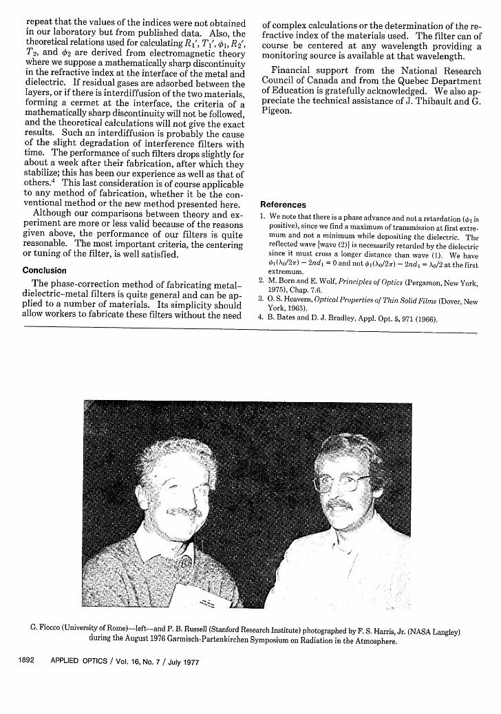
G. Fiocco (University of Rome)-left-and P. B. Russell (Stanford Research Institute) photographed by F. S. Harris, Jr. (NASA Langley)during the August 1976 Garmisch-Partenkirchen Symposium on Radiation in the Atmosphere.
1892 APPLIED OPTICS / Vol. 16, No. 7 / July 1977