facilities handbook for spacecraft assembly and
TRANSCRIPT

K-STSM-14.1.7-REVE-SAEF2April 1993
Facilities Handbook forSpacecraft Assembly andEncapsulation FacilityNumber 2
CONTRACT NAS 10-11400DRD CA-4
RELEASED


K-STSM-14.1.7April 1993Revision E
FACILITIES HANDBOOK
FOR
SPACECRAFT ASSEMBLY
AND
ENCAPSULATION FACILITY
NUMBER 2
Prepared by:
/s/Tracie WardmanTracie WardmanMDSS-KSC
Approved:
/s/P. Thomas Breakfield IIIP. Thomas Breakfield III, CSDirector, Shuttle Payload Operations
Approved:
/s/JoAnn H. MorganJoAnn H. Morgan, CPDirector, Payload Projects ManagementRELEASED

K-STSM-14.1.7April 1993Revision E
LIST OF EFFECTIVE PAGES
Revision E supersedes Revision D, dated September 1991.
Total number of pages in this publication is 48 consisting of:
Page No.
i/ii through xii1-1 thru 1-3/42-1 thru 2-63-1 thru 3-7/84-1 thru 4-3/45-1 thru 5-5/66-1 thru 6-47-1 thru 7-4
RELEASED
i/ii


K-STSM-14.1.7
TABLE OF CONTENTS
Sec/Par Title Page
I INTRODUCTION ............................................................................ 1-1
1.1 Purpose ....................................................................................... 1-11.2 Scope .......................................................................................... 1-11.3 Customer Charge......................................................................... 1-11.4 Facility Accommodations............................................................. 1-11.5 Hazardous and Controlled Waste................................................. 1-2
II FACILITY DESCRIPTION .............................................................. 2-1
2.1 Location and Description............................................................. 2-12.2 Explosive Restrictions.................................................................. 2-32.3 Personnel Access......................................................................... 2-32.4 Facility Use by Other Programs.................................................... 2-32.5 Functional Divisions..................................................................... 2-32.5.1 Airlock ..................................................................................... 2-32.5.2 High Bay.................................................................................. 2-32.5.3 Low Bays................................................................................. 2-32.5.4 Test Cell................................................................................... 2-52.5.5 Other Rooms ............................................................................ 2-52.5.6 Trailers..................................................................................... 2-5
III MECHANICAL SYSTEMS.............................................................. 3-1
3.1 Material Handling Equipment....................................................... 3-13.2 Compressed Air........................................................................... 3-13.3 Air-Conditioning.......................................................................... 3-13.4 Contamination Control and Monitoring System............................ 3-33.5 Vacuum System........................................................................... 3-43.6 Gaseous Nitrogen System............................................................ 3-43.7 Propellant Waste Drain System.................................................... 3-43.8 Krypton Vent, Hypergol Emergency Exhaust
Fans, and Hypergol Vent System................................................. 3-53.8.1 Krypton Vent............................................................................ 3-53.8.2 Hypergol Emergency Exhaust Fans........................................... 3-53.8.3 Hypergol Vent System.............................................................. 3-53.9 Fire Protection System................................................................. 3-53.10 Safety Equipment......................................................................... 3-63.11 Water System.............................................................................. 3-63.12 Sterilization Oven........................................................................ 3-63.13 Cranes and Hoists........................................................................ 3-63.13.1 Airlock and Test Cell Cranes..................................................... 3-63.13.2 High Bay Crane........................................................................ 3-7
RELEASED
iii
K-STSM-14.1.7
TABLE OF CONTENTS (continued)
Sec/Par Title Page
IV ELECTRICAL SYSTEMS............................................................... 4-1
4.1 Electrical Power........................................................................... 4-14.2 Illumination.................................................................................. 4-14.3 Grounding.................................................................................... 4-34.4 Lightning Protecting..................................................................... 4-34.5 Emergency Cutoff Switch............................................................. 4-34.6 Back-up Power............................................................................. 4-3
V BUILDING M7-1061 REMOTE CONTROL ROOMSAND SUPPORT AREAS............................................................... 5-1
5.1 Description................................................................................. 5-15.2 Access........................................................................................ 5-15.3 Customer Areas.......................................................................... 5-15.3.1 Office Areas............................................................................ 5-15.3.2 Conference Room................................................................... 5-15.3.3 Payload Control Rooms.......................................................... 5-15.4 Heating, Ventilating, and Air-Conditioning Systems.................... 5-15.5 Fire Protection Systems.............................................................. 5-55.5.1 Fire Detection System............................................................. 5-55.5.2 Fire Alarm System.................................................................. 5-55.5.3 Fire Control Equipment........................................................... 5-55.6 Electrical Systems....................................................................... 5-55.6.1 Alternating Current................................................................. 5-55.6.2 Illumination............................................................................. 5-55.6.3 Grounding Systems................................................................. 5-55.6.4 Lightning Protection............................................................... 5-55.6.5 Back-up Power ....................................................................... 5-5
VI COMMUNICATIONS AND DATA HANDLING ......................... 6-1
6.1 Communications......................................................................... 6-16.1.1 Operational Intercommunication System Digital...................... 6-16.1.2 Closed Circuit Television........................................................ 6-16.1.3 Other Communications........................................................... 6-16.2 Data Handling............................................................................. 6-16.2.1 Wideband Cable Transmission System..................................... 6-46.2.2 Reradiating Antenna System................................................... 6-46.2.3 Audio Frequency Capability.................................................... 6-4
RELEASED
iv
K-STSM-14.1.7
TABLE OF CONTENTS (continued)
Sec/Par Title Page
VII FACILITY DESCRIPTION SUMMARY, SAEF-2........................ 7-1
7.1 Safety......................................................................................... 7-17.2 Floor Space ................................................................................ 7-17.3 Ceiling Heights........................................................................... 7-17.4 Equipment Entry......................................................................... 7-27.5 Cranes........................................................................................ 7-27.6 Hook Heights ............................................................................. 7-27.7 Systems and Equipment.............................................................. 7-27.8 Temperature and Humidity......................................................... 7-37.9 Cleanliness Specifications............................................................ 7-37.10 Environmental Monitoring System.............................................. 7-37.11 Electrical Power......................................................................... 7-37.12 Illumination ................................................................................ 7-37.13 Communications......................................................................... 7-37.14 Data Handling............................................................................. 7-4
RELEASED
v/vi


K-STSM-14.1.7
LIST OF FIGURES
Figure Title Page
1-1 KSC/CCAFS Payload Processing Facilities....................................... 1-32-1 Spacecraft Assembly and Encapsulation Facility
Number 2..................................................................................... 2-12-2 Site Plan, SAEF-2............................................................................. 2-22-3 Floor Plan, SAEF-2.......................................................................... 2-43-1 Pneumatics, Air-Conditioning, EMS Enclosure, and
Vacuum System Locations in SAEF-2............................................ 3-24-1 Electrical Receptacles and Grounding Lugs, SAEF-2........................ 4-25-1 SAEF-2 Building M7-1061 Addition................................................ 5-25-2 Site Plan, Building M7-1061 ............................................................ 5-36-1 SAEF-2 Communications Systems.................................................... 6-26-2 Building M7-1061 Communications System...................................... 6-3
LIST OF TABLES
Table Title Page
2-1 SAEF-2 Room Specifications........................................................... 2-63-1 Cleanliness Requirements.................................................................. 3-34-1 Electrical Power Available in SAEF-2............................................... 4-15-1 SAEF-2 Building M7-1061 Room Specifications.............................. 5-46-1 RF Capability for SAEF-2................................................................. 6-4
RELEASED
vii/viii

K-STSM-14.1.7
LIST OF ABBREVIATIONS AND ACRONYMS
The following abbreviations and acronyms are used in this handbook. A more comprehensivelisting is contained in NASA Reference Publication 1059 Revised, Space Transportation Systemand Associated Payloads: Glossary, Acronyms, and Abbreviations.
A ampereac alternating currentACM access control monitorAE, AM, & AO building(s) on CCAFS
°C degrees CelsiusCCAFS Cape Canaveral Air Force StationCCTV closed circuit televisioncfm cubic feet per minutecm centimeterCWA clean work area
EPD emergency procedures documentESS electronic surveillance system
°F degrees Fahrenheitf-c foot-candleft foot
gal gallonGHz gigahertzGN2 gaseous nitrogen
HAD heat activated detectorsHEPA high efficiency particle air (filter)hp horsepowerHPF hazardous processing facilityHz Hertz
in inchIRIG Interrange Instrumentation Group
kg kilogramKSC John F. Kennedy Space Center
L literlb poundLC launch complexlm lumenLPS Launch Processing SystemLSSM Launch Site Support Manager
RELEASED
ix

K-STSM-14.1.7
LIST OF ABBREVIATIONS AND ACRONYMS (continued)
m meterMHz megahertzmin minute
NASA National Aeronautics and Space Administration
OISD Operational Intercommunications System DigitalOMI Operational Maintenance Instruction
PA public addressPACS Payload Access Control SystemPETS Payload Environmental Transportation SystemPGOC Payload Ground Operations ContractPPF payload processing facilitypsig pounds per square inch gage
RF radio frequency
SAA satellite accumulation areaSAEF Spacecraft Assembly and Encapsulation Facilityscfm standard cubic feet per minutesec secondSID Standard Interface Document
V voltVPF Vertical Processing Facility
WBTS Wideband Transmission System
% percent
RELEASED
x

K-STSM-14.1.7
FOREWORD
Launch site payload processing facilities are described in three levels of documentation. Theselevels and their purposes are:
a. K-STSM-14.1, Launch Site Accommodations Handbook for Payloads - This documentprovides a brief summary of each facility and a general description of John F. Kennedy SpaceCenter (KSC) launch and landing site operations.
b. Facility Handbooks - Each handbook provides a narrative description of the facility and itssystems. Also, general operating rules, regulations, and safety systems are discussed in thesehandbooks. Handbooks available are:
K-STSM-14.1.1 Facilities Handbook for Building AEK-STSM-14.1.2 Facilities Handbook for Building AOK-STSM-14.1.3 Facilities Handbook for Building AMK-STSM-14.1.4 Facilities Handbook for Hangar SK-STSM-14.1.6 Facilities Handbook for Explosive Safe Area 60AK-STSM-14.1.7 Facilities Handbook for Spacecraft Assembly and
Encapsulation Facility Number 2K-STSM-14.1.8 Facilities Handbook for Radioisotope Thermoelectric
Generator Storage BuildingK-STSM-14.1.9 Facilities Handbook for Life Sciences Support Facility
Hangar LK-STSM-14.1.10 *Payload Accommodations at the Rotating Service
StructureK-STSM-14.1.12 Facilities Handbook for Vertical Processing FacilityK-STSM-14.1.13 *Orbiter Processing Facility Payload Processing and
Support CapabilitiesK-STSM-14.1.14 *O&C Building Payload Processing
and Support CapabilitiesK-STSM-14.1.15 Facilities Handbook for Payload Hazardous Servicing
Facility
These facility handbooks are not under configuration control; however, they will be reissued asnecessary in order to maintain usefulness to customers in their planning for launch site processingof their payloads.
__________________
* These handbooks are titled differently because the facilities also serve functions other thanpayload support. Only the payload accommodations are described in these documents.
RELEASED
xi

K-STSM-14.1.7
c. Standard Interface Documents (SID's) - These documents are intended to provide thepayload-to-facility interface design details for these launch site payload processing facilities.
SID 79K12170 Payload Ground Transportation CanisterSID 79K16210 Vertical Processing FacilitySID 79K16211 Horizontal Processing Facility (O&C Building)SID 79K17644 Payload StrongbackSID 79K18218 Launch Pad 39ASID 79K28802 Launch Pad 39BSID 79K18745 Orbiter Processing FacilitySID 82K00463 Payload Environmental Transportation System
Multiuse Container
SID's are not available for all launch site payload processing facilities. In these cases, the facilityhandbooks must be used for design interface information and customers should ask forverification of any areas of concern. When SID's are available, they should be used as the officialdefinition of the facility interfaces. There are some SID's for which there are no handbooks; e.g.,the payload strongback and the Payload Environmental Transportation System (PETS) multiusecontainer. In these cases, the SID's must be used.
Customers may obtain copies of any of these documents through the assigned Launch SiteSupport Manager (LSSM).
RELEASED
xii

K-STSM-14.1.7
SECTION I
INTRODUCTION
1.1 PURPOSE
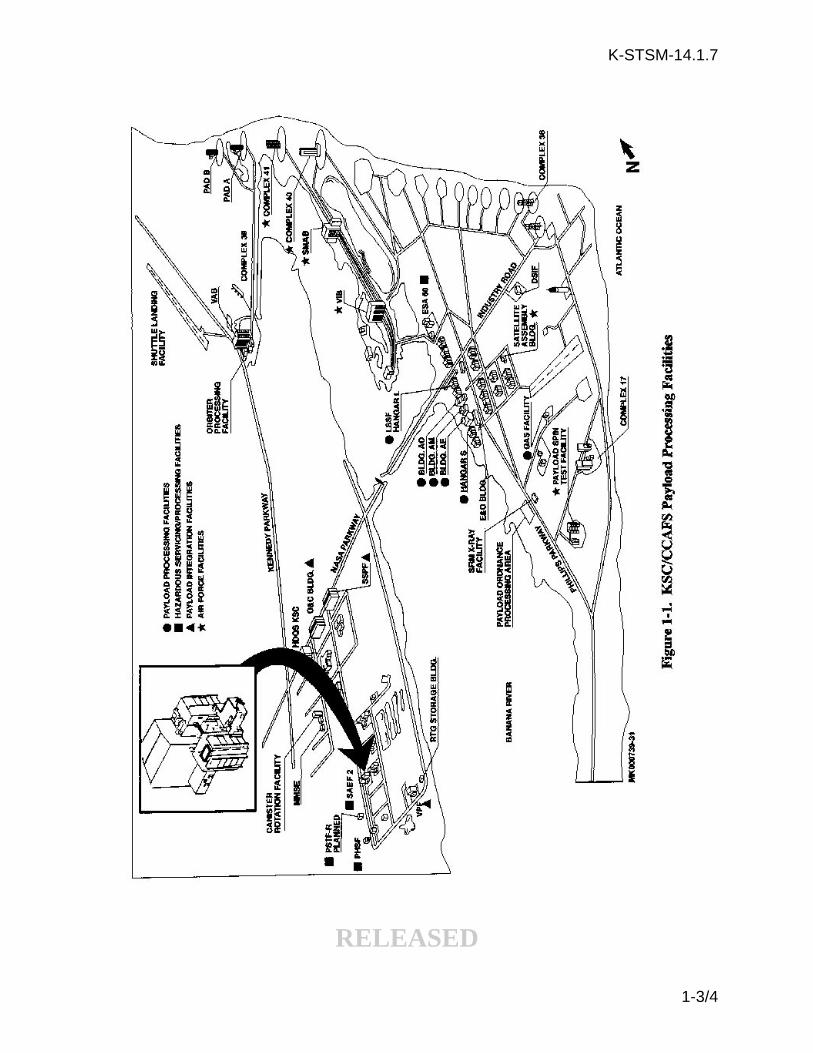
The purpose of this handbook is to provide basic information regarding payload processing andsupport capabilities in the Spacecraft Assembly and Encapsulation Facility Number 2 (SAEF-2), ahazardous processing facility (HPF), at KSC. The facility and its location are shown in figure 1-1.This facility was designed and constructed to accommodate ordnance installation, liquidpropellant (hypergols) loading, hazardous systems tests and checkout, buildup, and any otherpotentially explosive or hazardous operations.
The KSC Launch Site Support Manager (LSSM), in conjunction with the Launch Site SupportTeam and the customer, will determine launch site facility utilization assignments based onidentified payload requirements and overall Space Shuttle schedules or National Aeronautics andSpace Administration (NASA) purchased Expendable Vehicles schedules. The documentsidentified in the Foreword describe the configuration of the Cape Canaveral Air Force Station(CCAFS) and KSC off-line payload processing facilities (PPF's) and HPF's which are available topotential customers.
1.2 SCOPE
This handbook is intended to be used by the customer as a guide for planning of payload activitiesin SAEF-2. It describes the capabilities and standardized interfaces of SAEF-2.
1.3 CUSTOMER CHARGE
Use of SAEF-2 for payload processing is considered an optional service.
1.4 FACILITY ACCOMMODATIONS
The facility accommodations available to the customer as identified herein provide support to avariety of NASA and NASA customer payloads and may accommodate payload elements beingprocessed simultaneously. The customer must remain cognizant during design development ofthe necessity to share these facilities with other payload elements. Individual customerrequirements should be coordinated closely with the KSC LSSM to assure that support isavailable when needed.
The SAEF-2 is a customer-operated facility. The customer is responsible for day-to-dayoperations including assuring someone in their team is certified by MDSS to open and close thepowered door. The Payload Ground Operations Contractor (PGOC) is responsible for cranepreoperation checks.
Customers will be familiar with the "Spacecraft Assembly and Encapsulation Facility Number 2(SAEF-2) M7-1210, Emergency Procedures Document (EPD), Operational MaintenanceInstruction (OMI) No. 59930."
RELEASED
1-1

K-STSM-14.1.7
1.5 HAZARDOUS AND CONTROLLED WASTE
In advance of their arrival, customers will fill out KSC Form 26-551, "Process WasteQuestionnaire," for any hazardous and controlled waste they expect to generate at KSC duringprocessing. All waste generated at KSC will be managed in accordance with the requirements ofKHB 8800.7, Hazardous Waste Management.
Once a customer has identified launch site waste generations, a satellite accumulation area (SAA)will be set up in facilities denoted as points of generation of these wastes.
These SAA's will be established in order to comply with the intent of the Resource and RecoveryAct of 1976, which was established to institute a national program to control the generation,storage, transportation, treatment, and disposal of hazardous and controlled waste.
Customers should coordinate any waste operations or problems with their assigned LSSM.Regulations for the use of, control of, and disposal of waste at the launch site are strictlyenforced.
RELEASED
1-2
K-STSM-14.1.7
RELEASED
1-3/4

K-STSM-14.1.7
SECTION II
FACILITY DESCRIPTION
2.1 LOCATION AND DESCRIPTION
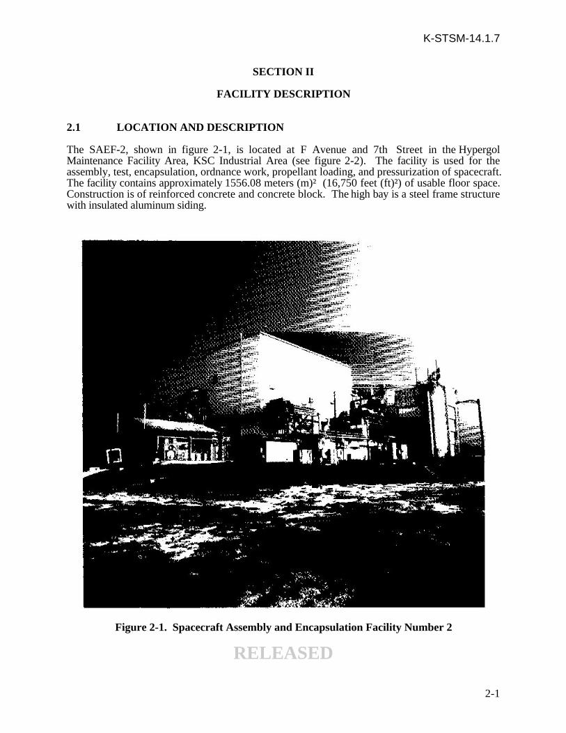
The SAEF-2, shown in figure 2-1, is located at F Avenue and 7th Street in the HypergolMaintenance Facility Area, KSC Industrial Area (see figure 2-2). The facility is used for theassembly, test, encapsulation, ordnance work, propellant loading, and pressurization of spacecraft.The facility contains approximately 1556.08 meters (m)² (16,750 feet (ft)²) of usable floor space.Construction is of reinforced concrete and concrete block. The high bay is a steel frame structurewith insulated aluminum siding.
Figure 2-1. Spacecraft Assembly and Encapsulation Facility Number 2
RELEASED
2-1

K-STSM-14.1.7
Figure 2-2. Site Plan, SAEF-2
RELEASED
2-2

K-STSM-14.1.7
2.2 EXPLOSIVE RESTRICTIONS
Information concerning explosive restrictions will be determined by NASA-KSC Safety on amission by mission basis.
2.3 PERSONNEL ACCESS
Because of the extreme hazard associated with explosives and propellants, stringent safetymeasures and security controls are enforced. Access to the facility will be controlled by a PGOCAccess Control Monitor (ACM). The facility will be secured at all times when not manned by anACM except that during periods when no flight hardware is present. The electronic PayloadAccess Control System (PACS) may be used in lieu of the ACM. The operational areas arecontrolled by electronic surveillance equipment including closed circuit television (CCTV),motion detection equipment and door alarms.
2.4 FACILITY USE BY OTHER PROGRAMS
Like all launch support facilities assigned to a particular project or resident contractor group,SAEF-2 is available to other programs on a non-interference basis if no other suitable facility isavailable.
2.5 FUNCTIONAL DIVISIONS
Functionally, the building is divided into the following areas: a clean work area (CWA) complexconsisting of an airlock, a high bay, and two low bays; a test cell; a sterilization oven (non-operational); support office areas; and mechanical equipment rooms (figure 2-3). Floors in theairlock, high bay, and test cell are designed for 3175.20 kilogram (kg) (7000 pounds (lb)) perwheel plus 20 percent impact loading.
2.5.1 AIRLOCK. The airlock, located at the north end of the building, measures 12.5 m by17.7 m (41 ft wide by 58 ft long), providing a usable floor area of 221 m² (2378 ft²) and is ratedas a Class 300,000 CWA. The airlock has a clear ceiling height of 15.9 m (52 ft). Access is bymeans of personnel doors, vestibule, and a 6.4 m by 12.2 m (21.5 ft wide by 40 ft high) verticallift equipment door. A 6.5 m by 12.1 m (21 ft wide by 39.5 ft high) horizontal sliding lift doorseparates the airlock from the adjacent high bay.
2.5.2 HIGH BAY. The high bay measures 14.9 m by 30.2 m (49 ft wide by 99 ft long),providing a usable floor area of 450.7 m² (4851 ft²); clear ceiling height is 22.6 m (74 ft) and israted as a Class 100,000 CWA. Personnel and small equipment can enter the high bay throughthe equipment airlock, equipped with air showers. Clear access is 1.4 m by 2.1 m (4 ft 5 in wideby 6 ft 11 in high).
2.5.3 LOW BAYS. Two large bays are located along the west side of the high bay. One ofthe bays measures 5.8 m by 21.9 m (19 ft wide by 72 ft long) with a clear ceiling height of 7.62 m(25 ft); the other bay is 5.8 m by 8.2 m (19 ft wide by 27 ft long) and has a clear ceiling height of13.3 m (43.5 ft). The combined bay areas provide a usable floor space of 174.8 m² (1881 ft²).The low bays are also rated as Class 100,000 CWA's.
RELEASED
2-3

K-STSM-14.1.7
Figure 2-3. Floor Plan, SAEF-2
RELEASED
2-4

K-STSM-14.1.7
2.5.4 TEST CELL. The test cell is located at the northeast corner of the facility. The cellmeasures 11.3 m by 11.3 m (37 ft by 37 ft), providing a usable floor area of 127.2 m² (1369 ft²).The clear ceiling height is 15.9 m (52 ft). Access to the test cell is by means of personnel doorsand three 6.7 m by 12.2 m (22 ft wide by 40 ft high) vertical lift doors. The test cell can be usedfor spacecraft and payload support activities not requiring Class 100,000 CWA conditions.
2.5.5 OTHER ROOMS. The remainder of the building consists of such support rooms asa mechanical equipment room, communication equipment room, entry and observation room,change room, storage room, miscellaneous equipment rooms, and limited office space. Table 2-1provides room specifications for SAEF-2.
The sterilization oven is located at the south end of the facility in a 13.1 m by 16.2 m (43 ft wideby 53 ft long) open-sided shed. Ceiling height of the shed in the oven area is 4.9 m (16 ft). (Theoven is not operational.)
There is a 13.7 m by 8.5 m (45 ft long by 28 ft wide) conference area located on the second floorabove rooms 117 and 119.
Room 109 is used as the clean room garment storage and issue room.
2.5.6 TRAILERS. There are five 3.7 m by 18.3 m (12 ft by 60 ft) office trailers, figure2-3, available for payload personnel use when their payload is in SAEF-2. Two are on the northside of the building; two, on the west side; and one, on the east side. One of the trailers locatedon the north side is used by the NASA and PGOC facility managers.
RELEASED
2-5

K-STSM-14.1.7
Table 2-1. SAEF-2 Room Specifications
RELEASED
2-6

K-STSM-14.1.7
SECTION III
MECHANICAL SYSTEMS
3.1 MATERIAL HANDLING EQUIPMENT
Both the airlock and the test cell each have a 9.08 metric ton (10-ton) bridge crane that operateon their own twin runway girder rails. The hook height at both locations is 13.7 m (45 ft).
The high bay CWA has a 18.16 metric ton (20-ton) bridge crane that operates on twin runwaygirder rails; the hook height is 19.9 m (65 ft 5 in). See paragraph 3.13 for additional data oncrane operations.
Cranes may be operated only by trained personnel. The KSC contractor support personnel willprovide crane training for customer personnel as required in accordance with KennedyManagement Instruction 6430.4, Examination and Licensing of KSC Facility Crane Operators.Physical examinations are a prerequisite to crane training.
3.2 COMPRESSED AIR
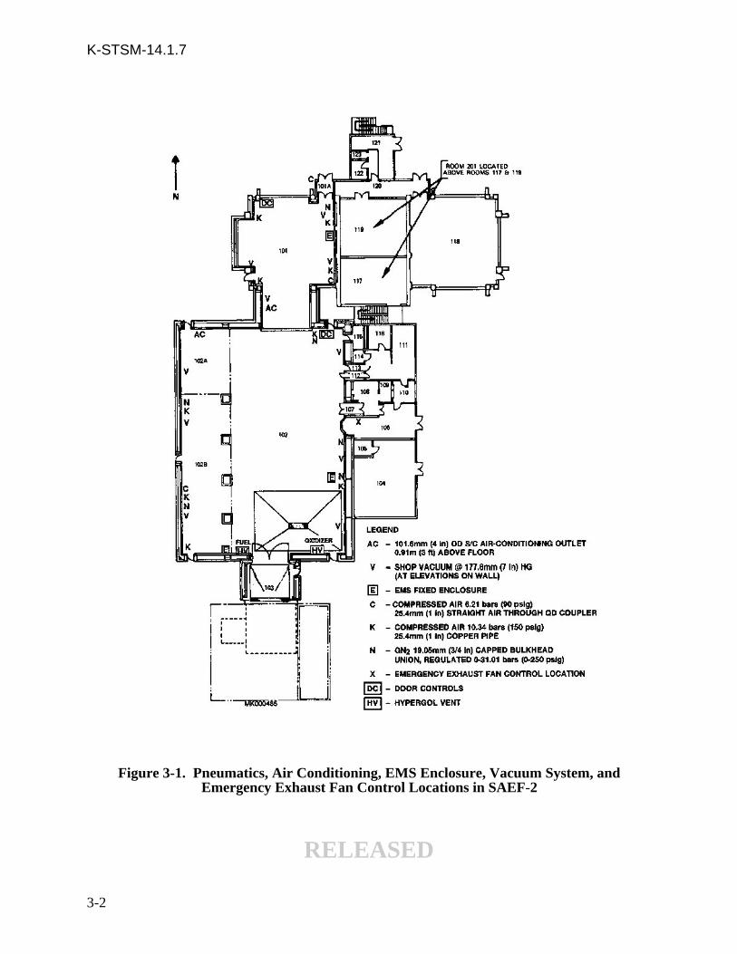
Compressed air is available at 6.2 and 10.3 bars (90 and 150 pounds per square inch gage (psig));170 standard cubic ft per minute (scfm) nonregulated and 300 scfm nonregulated in the airlock,CWA, and oven area. See figure 3-1 for outlet locations. Each active outlet is equipped with ashutoff valve, a filter, a moisture trap, and a quick-disconnect fitting. Air compressing equipmentis located in room 104. Compressed air systems are not clean systems, (not certified to KSC-C-123) however, air provided to the CWA's passes through three-micron final filters and will notdegrade room cleanliness.
3.3 AIR-CONDITIONING
All operational areas of this building are environmentally controlled. Temperature control ismaintained at 21.7 ± 3.3 ºC (71 ± 6 ºF) with a relative humidity of 50 percent or less. The air-conditioning system is high efficiency particle air (HEPA) filtered and fed by five air handlersrecirculating the air 11 times each hour. The CWA fresh air is replenished 2.5 times each hour.
The high bay is a Class 100,000 CWA. Personnel enter the high bay area through an air showerin room 112. High bay floors are tiled, and walls are painted gypsum wallboard. The airlock canbe cleaned and maintained as a Class 300,000 CWA. Primary use for the airlock is cleaning andpreparation of hardware before entry into the high bay. The customer provides the cleaningequipment and agent. Both the clean room and the airlock have a 10.16 cm (4 in) outsidediameter spacecraft air-conditioning outlet, MS33660-64 Type A bead, 0.91 m (3 ft) above thefloor for auxiliary air-conditioning service. See figure 3-1 for air-conditioning service locations.
Air-conditioning systems in the remote SAEF-2 payload control room building will maintain theoffice areas at 25.6 ºC (78 ºF) in the summer and 22.2 ºC (72 ºF) in the winter. The controlrooms will be maintained at 22.2 ºC (72 ºF) throughout the year. All areas will be maintained at arelative humidity of 50 percent or less.
RELEASED
3-1
K-STSM-14.1.7
Figure 3-1. Pneumatics, Air Conditioning, EMS Enclosure, Vacuum System, andEmergency Exhaust Fan Control Locations in SAEF-2
RELEASED
3-2

K-STSM-14.1.7
3.4 CONTAMINATION CONTROL AND MONITORING SYSTEM
The SAEF-2 is a partial laminar flow CWA. The high bay is rated as a CWA level 4 and theairlock is rated as a CWA level 5.
An Environmental Monitoring System provides real-time and historical data on the necessaryparameters relative to maintaining a clean working environment and is supplemented by physicalmeasuring techniques. Environmental conditions are continuously monitored, stored, andrecorded for temperature, relative humidity, and airborne particle concentration. Surfaceparticulate matter, nonvolatile residue, and volatile hydrocarbon monitoring is performed byconventional methods. (See table 3-1 for cleanliness requirements.)
Table 3-1. Cleanliness Requirements [1]
Clean Work Area Levels Level #4 Level #5
Parameter Air Flow Non-Laminar Non-Laminar
Maximum Airborne Req ≥ 0.5 µm 100,000 300,000Particle Counts (Per Req ≥ 5.0 µm 700 1,000Cubic Foot) Monitoring Continuous Monthly
Temperature (°F) [3] Requirement 71±6 71±6Monitoring Continuous Monthly
Relative Humidity Requirement 50 Max 50 Max(Percent) [3] Monitoring Continuous Monthly
Maximum Particle Fallout Goal Level 750 Level 1000[2] Monitoring Continuous Every 6 Months
Maximum NVR Requirement 1.0 2.0(mg/0.1m²/month) Monitoring Continuous Annually
Maximum Volatile Requirement 15 N/AHydrocarbons (PPM) (v/v) Monitoring Every 2 Weeks N/A
Minimum Positive PressureRequirement 0.02 in. H2O N/AMonitoring Daily N/A
Minimum Air Changes Requirement 4/Hour 2/Hour
[1] During Periods of Operation[2] Levels Per MIL-STD-1246 for a 24-Hour Period[3] Program OMRSD May Supersede These Requirements
RELEASED
3-3

K-STSM-14.1.7
Sensor sets have been installed in recessed purged cabinets in south and east walls of the high bayand in similar recesses in the east wall of the airlock (see figure 3-1). Each set contains atemperature sensor that reads ºF, a relative humidity sensor that reads percentage, and a laserparticle counter that measures airborne particle concentration.
The Continuous Monitor/Analyzer, referred to as the mainframe, is the heart of the monitoringequipment. The mainframe is centrally located and remote from the sensors. The multiple sensoroutputs are connected by coaxial cable. The mainframe identifies the information from thesensors, files it in time-correlated channels of data, and provides an output to the host computersystem. The mainframe and the computer are located in room 106. Real time data and a printedrecord of environmental out-of-specification conditions (if any) are available from the computer.During propellant operations, toxic vapor detectors are activated (one oxidizer and fuel set in theairlock and one set in the high bay) and results of their sampling are also available from theprinted computer record.
3.5 VACUUM SYSTEM
The high bay and airlock are serviced with a vacuum system at 17.78 cm (7 in) of mercury forcleaning purposes. See figure 3-1 for outlet locations. Outlets are placed in three elevations onthe walls: the floor, midway on the wall, and near the ceiling.
3.6 GASEOUS NITROGEN (GN2) SYSTEM
GN2 is provided in 17.24 bars (250 psig) to the CWA and airlock through wall-mounted 1.9 cm(3/4 in) KSC capped bulkhead unions. See figure 3-1 for locations. This system is certifiable toKSC-SPEC-123, level 300. GN2 can be provided to the east test cell from an exterior mobiletube bank.
3.7 PROPELLANT WASTE DRAIN SYSTEM
This is a non-storage system to be used for contingency spills during hypergolic operations. Itconsists of a trench drain with an oxidizer and fuel drain line to their respective stainless steeltanks. All leaks and spills should be immediately removed by use of an aspirator.
A 18925 L (5000 gallon (gal)) stainless steel waste fuel tank is located underground southeast ofthe building. There is also one 18925 L (5000 gal) stainless steel oxidizer waste tank locatedunderground east of the building next to the cooling tower.
A line leading to the waste tanks is located in rooms 102 and 103. Waste from the sterilizationoven area is carried through a 10.2 cm (4 in) stainless steel pipe to the tank.
NOTE
Use of this drain system should never be a planned part of anyhypergolic operation
RELEASED
3-4

K-STSM-14.1.7
3.8 KRYPTON VENT, HYPERGOL EMERGENCY EXHAUST FANS, ANDHYPERGOL VENT SYSTEM
3.8.1 KRYPTON VENT. The Krypton vent consists of an internal bulkhead connecting toan external vent stack leading to the top of the south side of the high bay.
3.8.2 HYPERGOL EMERGENCY EXHAUST FANS. Six manually initiated belt-drivencentrifugal exhaust fans have been installed in the bay area: two 1-horsepower (hp) fans rated at1784.15 L/second (sec) (3780 cubic ft per minute), two 3-hp fans rated at 4158.32 L/sec (8810cfm), and two 3-hp fans rated at 3573.04 L/sec (7570 cfm). Keyswitch controls for this systemare located in the SAEF-2 observation room and on console 2 in each M7-1061 control room.
The emergency exhaust system, also called the remote control emergency exhaust assembly, ispart of the heating, ventilation, and air-conditioning system at SAEF-2 and is used to exhaustresidual fumes after cleanup of a hypergol spill.
Activation of a keyswitch control start button will stop air handlers 1, 2, 3, and 4, close return airdampers and open purge exhaust dampers, open outside air dampers, open emergency systemintake dampers, and start all exhaust fans.
Activation of a keyswitch control stop button stops the purge fans, repositions the dampers totheir normal position, and restarts the air handling unit supply fans.
Three manually initiated belt-driven centrifugal 10-hp exhaust fans rated at 9534.40 L/sec each(20,200 cfm each) have been installed in the test cell area and work in conjunction with airhandler 8.
3.8.3 HYPERGOL VENT SYSTEM. Hypergol vents are located on the south wall of thehigh bay. Vapors are piped into the respective fuel or oxidizer separators, travel into the hypergolscrubber system, and are vented. Aspirated (vacuumed) hypergol liquids are retained in theaspirator and vapors are exhausted through the hypergol vents.
3.9 FIRE PROTECTION SYSTEM
Heat detectors are installed in the ceiling of most rooms. Smoke detectors are installed in theairlock and high bay CWA air-conditioning ducts. Hand-operated, pull-type fire alarm boxes arealso located at strategic places throughout the building. Activation of either alarm causes a codedsignal to be transmitted to the KSC Launch Control Center, Room 1P10, KSC ProtectiveServices Control Center. At the same time, alarm bells are sounded in and around the building.
SAEF-2 has a water deluge system with nozzles that protrude from the wall in the south third ofthe high bay. There are also spray heads in recesses in the ceiling above this same area and sprayheads in recesses in the ceilings of the passageway and the south half of the low bay. Controls forthis system are located on the wall adjacent to all the emergency exits, on thenorth wall of the observation room, and on the appropriate payload control room console inBuilding M7-1061. Only the controls in the observation room and the Payload Control Rooms inBuilding M7-1061 have a shutoff capability.
RELEASED
3-5

K-STSM-14.1.7
NOTE
To help preclude the deluge system from being turned on inadvertently, two distinctactions must be taken before it can be activated; the system must be armed and thenactivated.
A wet-pipe automatic sprinkler system is provided over each of the two scrubbers under a canopyat the south end.
3.10 SAFETY EQUIPMENT
Amber and red flashing omnidirectional lights are mounted on the outside of the building abovethe roof line. These lights are used to indicate that hazardous operations are being conductedinside the building. An eyewash and safety shower are located approximately 1.5 m (5 ft) fromthe southeast corner of the building. Eyewash and safety showers are located at each of the wastetanks (fuel and oxidizer) and between the fuel and oxidizer scrubbers.
3.11 WATER SYSTEM
Hot and ambient temperature water is supplied to various locations throughout the high bay,airlock, and sterilization oven areas by means of 1.3 cm (1/2 in) and 1.9 cm (3/4 in) pipes throughstandard hose bibbs. The maximum waterflow rate is between 26.5 and 37.9 L/min (7 and 10gallons per minute). Heating is provided by temperature control.
3.12 STERILIZATION OVEN
A 13.1 m by 16.2 m (43 ft wide by 53 ft long) open-sided shed that houses the sterilization oven,once used for sterilization of planetary probe spacecraft, is located at the south end of the facility.The oven measures 6.4 m by 6.7 m by 4.9 m (21 ft by 22 ft by 16 ft high). Outside the oven arethe following:
a. Hazardproof lights and Operational Intercommunication System Digital (OIS-D)b. Safety shower and eyewash fountainsc. Catch basin for leaks or spills, with a drain line to the waste fuel tank
The area is currently used for non-air-conditioned storage and is located immediately south ofroom 103.
3.13 CRANES AND HOISTS
Three bridge cranes are available in the facility. The airlock (room 101) and the test cell (room118) each have a 9.1 metric ton (10-ton) crane and the high bay (room 102) has a 18.2 metric ton(20-ton) crane.
3.13.1 AIRLOCK AND TEST CELL CRANES. The two 9.1 metric ton (10-ton) bridgecranes are identical in design and installation. Each hoist bridge operates on twin runway girderrails and is powered by a two-speed 0.6 m/min or 1.8 m/min (2 ft/min or 6 ft/min) motor. Poweris supplied through festoon cabling supported by a carrier assembly and track. In a similarmanner, the trolley moves on twin bridge rails and is powered by the same type of motor as isused on the bridge. The electrical power is also supplied to the trolley unit through festoon
RELEASED
3-6

K-STSM-14.1.7
cabling supported by a carrier assembly and track. Speeds for the trolley are 0.6 m/min or 1.8m/min (2 ft/min or 6 ft/min). Both the trolley and bridge automatically come to a stop at theextreme ends of their travel due to activation of travel limit switches and the setting ofelectromagnetic brakes. The cranes are controlled from the floor by cable and pendantpushbutton switches for speed selection (SLOW and FAST) and one indicator light thatilluminates when power is applied. One remote power control panel with an indicator light foreach crane is provided to allow emergency power cutoff from the second floor, room 201.
The crane, powered by a two-speed motor, is capable of lifting a load to a height of about 13.7 m(45 ft) at 0.6 m/min or 1.8 m/min (2 ft/min or 6 ft/min). The crane is equipped with a standardbrake capable of stopping and holding a 9.1 metric ton (10-ton) load. The electromagnetic brakeis backed up by a mechanical load brake. Additionally, a counter-weighted limit switch and upperand lower-geared limit switches are provided for protection against over-travel of the hoist hookblock.
Purge lines (GN2) with necessary pressure gage, shut-off valves, and bleed-off valves are providedfor the purge of the explosionproof pendant control and relay control cabinet. The purge systemis available in the airlock and in room 118.
3.13.2 HIGH BAY CRANE. The bridge crane, located in the high bay CWA, is designed toprovide a lifting capability of 18.2 metric tons (20-tons). The bridge crane operates on twinrunway girder rails and is powered by a one-speed, 0.46 m/min (1.5 ft/min) micromotor and atwo-speed, 2.1 m/min or 6.4 m/min (7 ft/min or 21 ft/min) main motor. Power is suppliedthrough a cable reel assembly.
In a similar manner, the trolley moves on twin bridge rails and is powered by the same types ofmicromotor and main motor that are used on the bridge. Electrical power is supplied to thetrolley through a cable reel assembly. Speeds for the trolley are 0.46 m/min (1.5 ft/min),2.2m/min (7.33 ft/min), or 6.7 m/min (22 ft/min). Both the bridge and trolley will automaticallycome to a stop at the extreme ends of their travel due to activation of travel limit switches and thesetting of electromagnetic brakes.
The crane is controlled by a cable and pendant pushbutton station suspended from the bridgeassembly. The pendant is equipped with six pushbutton switches for operation of the crane,trolley, and bridge; and two pushbutton switches for power application (ON-OFF). The crane ispowered by a one-speed 0.5 m/min (1.5 ft/min) micromotor and a two-speed, 2.13 m/min or 6.4m/min (7 ft/min or 21 ft/min) main motor and is capable of lifting a load to a height of 19.2 m (63ft) at 0.46, 2.13 or 6.4 m/min (1.5, 7, or 21 ft/min). The crane is equipped with a standard brakecapable of stopping and holding a 18.2 metric ton (20-ton) load. The electromagnetic brake isbacked up by a mechanical load brake. A counterweight limit switch and an upper and lower-geared limit switch are provided for protection against over-travel of the hoist hook block.
The 18.2 metric tons (20-ton) overhead crane travel is within 1.8 m (6 ft) of the west high baywall, 1.2 m (4 ft) of the east wall, to 3.2 m (10 ft 6 in) of the south wall, and 2.6 m (8 ft 6 in) ofthe north wall. It has a explosionproof pendant pushbutton control station. Hook heightmaximum is 19.9 m (65 ft 5 in).
RELEASED
3-7/8

K-STSM-14.1.7
SECTION IV
ELECTRICAL SYSTEMS
4.1 ELECTRICAL POWER
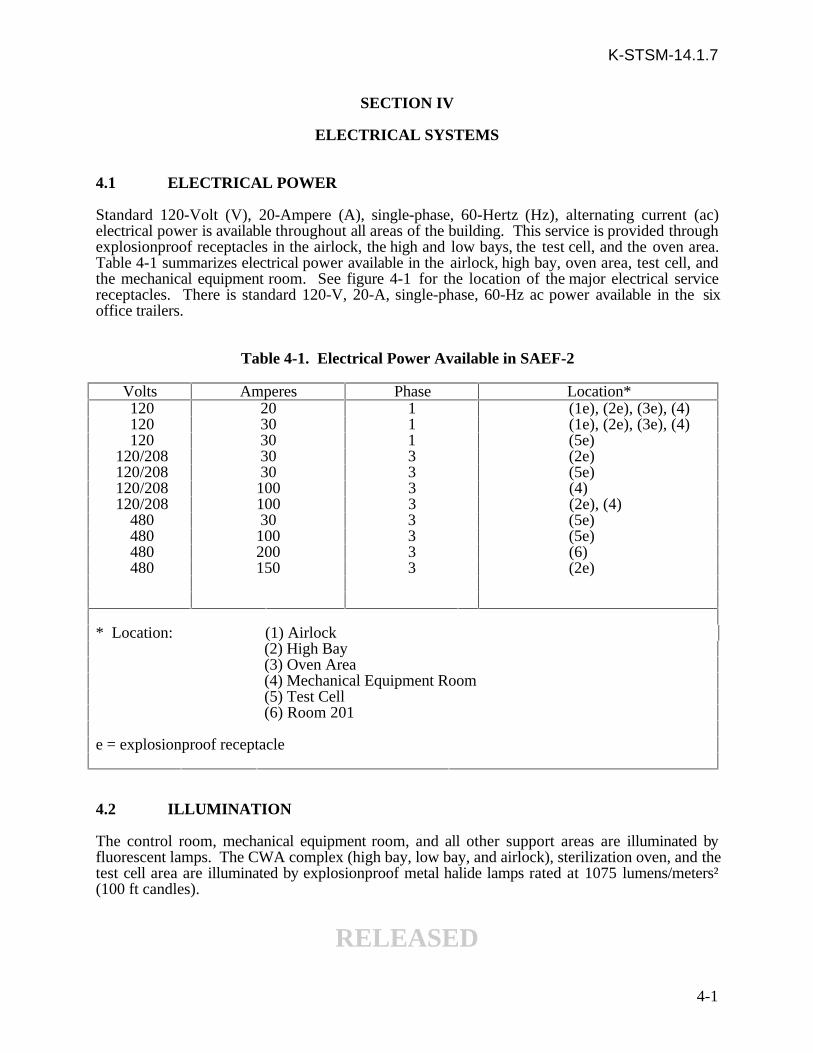
Standard 120-Volt (V), 20-Ampere (A), single-phase, 60-Hertz (Hz), alternating current (ac)electrical power is available throughout all areas of the building. This service is provided throughexplosionproof receptacles in the airlock, the high and low bays, the test cell, and the oven area.Table 4-1 summarizes electrical power available in the airlock, high bay, oven area, test cell, andthe mechanical equipment room. See figure 4-1 for the location of the major electrical servicereceptacles. There is standard 120-V, 20-A, single-phase, 60-Hz ac power available in the sixoffice trailers.
Table 4-1. Electrical Power Available in SAEF-2
Volts Amperes Phase Location* 120 20 1 (1e), (2e), (3e), (4) 120 30 1 (1e), (2e), (3e), (4) 120 30 1 (5e)
120/208 30 3 (2e) 120/208 30 3 (5e) 120/208 100 3 (4) 120/208 100 3 (2e), (4)
480 30 3 (5e) 480 100 3 (5e) 480 200 3 (6) 480 150 3 (2e)
* Location: (1) Airlock(2) High Bay(3) Oven Area(4) Mechanical Equipment Room(5) Test Cell(6) Room 201
e = explosionproof receptacle
4.2 ILLUMINATION
The control room, mechanical equipment room, and all other support areas are illuminated byfluorescent lamps. The CWA complex (high bay, low bay, and airlock), sterilization oven, and thetest cell area are illuminated by explosionproof metal halide lamps rated at 1075 lumens/meters²(100 ft candles).
RELEASED
4-1

K-STSM-14.1.7
Figure 4-1. Electrical Receptacles and Grounding Lugs, SAEF-2
RELEASED
4-2
K-STSM-14.1.7
4.3 GROUNDING
All structural metal, appropriate metallic components and equipment, the conductive vinyl tilefloor in the airlock and service bay, and lightning air terminals are connected to the structuralgrounding system. This system consists of 15 interconnected rods located around the peripheryof the building. Isolated equipment grounds are located in the control room and the mechanicalequipment room. See figure 4-1 for location of countersunk grounding lugs.
4.4 LIGHTNING PROTECTION
Lightning protection is provided by an interconnected system of roof-mounted air terminals anddown conductors connected to the building steel and subsequently to the counterpoise.
4.5 EMERGENCY CUTOFF SWITCH
A single-point electrical emergency cutoff circuit is provided. A receptacle is mounted on the eastwall, near the observation window, where a 30.48 m (100 ft) cord with an activation button canbe plugged in. Activation of this button will remove ac power from the 120 V and 120/208 Voutlets in the high bay used for test or monitoring equipment.
4.6 BACK-UP POWER
Provisions have been made for back-up power to be supplied by a government-furnished dieselgenerator through a manual transfer switch located in room 104. This back-up system will onlysupply power to the bay cranes, receptacles, and lights.
RELEASED
4-3/4


K-STSM-14.1.7
SECTION V
BUILDING M7-1061 REMOTE CONTROL ROOMSAND SUPPORT AREAS
5.1 DESCRIPTION
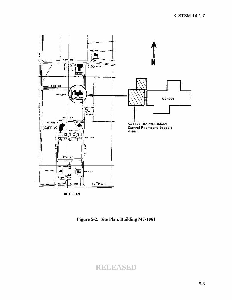
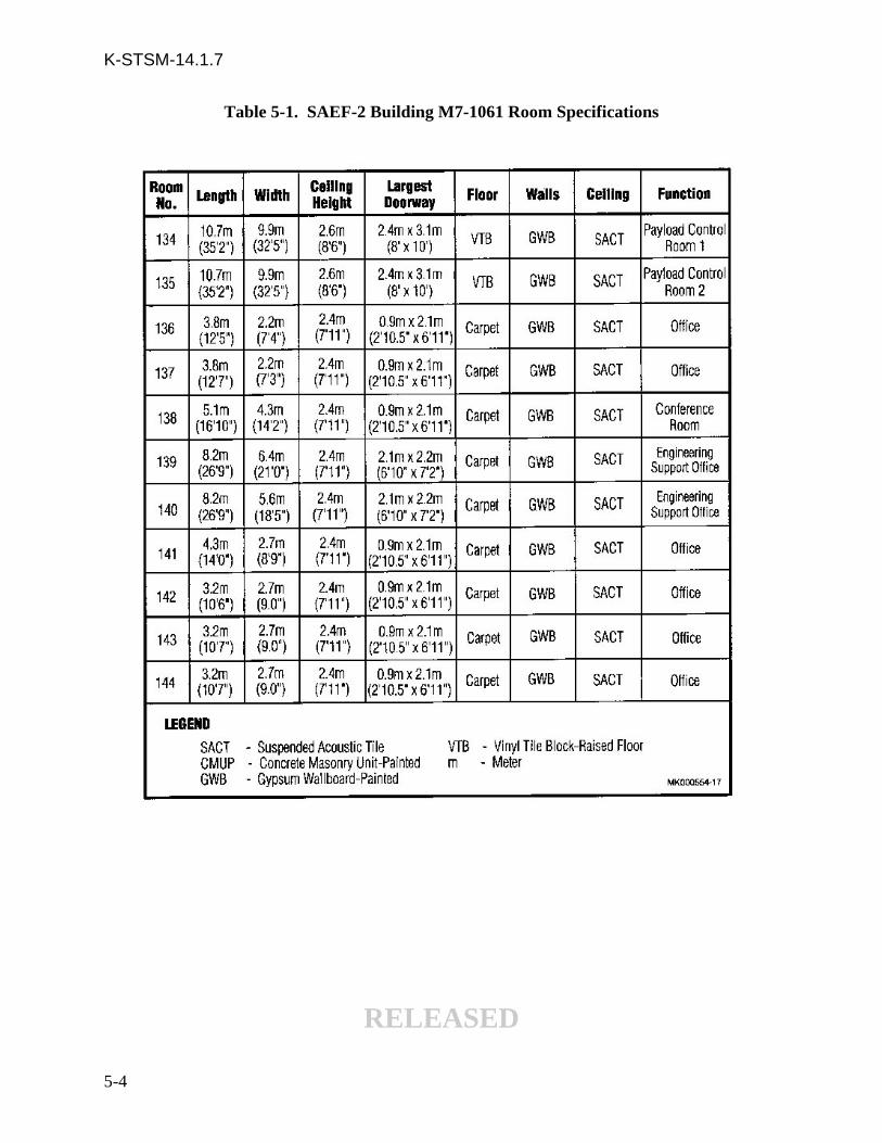
The remote control rooms and support areas, figure 5-1, are located approximately 205.7 m (675ft) northeast of the SAEF-2, figure 5-2. They were built as an addition to existing Building M7-1061, and are interconnected to SAEF-2 by a cableway. This addition is a prefabricated steelbuilding covered on the exterior with insulated metal siding and was designed to be the office areaand payload control rooms for customers using the SAEF-2. See table 5-1 for roomspecifications.
5.2 ACCESS
Personnel have free access to the customer areas during normal duty hours with exception of thepayload control rooms when a customer elects to limit entry through an access list. The LSSMwill coordinate the preparation of Entry Authorization Lists.
5.3 CUSTOMER AREAS
5.3.1 OFFICE AREAS. Rooms 136, 137, 141, 142, 143, and 144 are normally utilized ascomfortable individual offices while rooms 139 and 140 can each comfortably seat several supportpersonnel.
5.3.2 CONFERENCE ROOM. This room is adjacent to room 139 and can comfortablyseat 15 persons.
5.3.3 PAYLOAD CONTROL ROOMS. These rooms function as the customer groundstation for checkout and testing of their payload located in SAEF-2. They are separated by arolling door that can be opened to provide use of both rooms by a single customer if necessary.
There are six consoles in each room; 1, 4, and 6 are available for customer use, and 2, 3, and 5 areoperated by either NASA or PGOC.
Consoles 1 and 6 are video switchers and each contains two monitors and two switchers.Console 4 functions as the customer test director console and contains an OIS-D panel, apaging/area warning and evacuation panel, and the test director page and zone area switch panel.
Console 2 is the safety console and controls the SAEF-2 water deluge system and emergencyexhaust fan system. Console 2 also contains the paging/area warning and evacuation panel andthe safety page and zone area switch panel. Console 3 functions as the CCTV control panel andcontains two monitors, one switcher and a countdown clock. Console 5 functions as both thedirect current power and the fuel and oxidizer scrubbers control panel.
5.4 HEATING, VENTILATING, AND AIR CONDITIONING SYSTEMS.
The payload control rooms and office support areas air-conditioning and reheat systems canmaintain a temperature of 21.7 ± 3.3 ºC (71 ± 6 ºF) with a relative humidity of 50 percent or less.
RELEASED
5-1

K-STSM-14.1.7
Figure 5-1. SAEF-2 Building M7-1061 Addition
RELEASED
5-2
K-STSM-14.1.7
Figure 5-2. Site Plan, Building M7-1061
RELEASED
5-3
K-STSM-14.1.7
Table 5-1. SAEF-2 Building M7-1061 Room Specifications
RELEASED
5-4
K-STSM-14.1.7
5.5 FIRE PROTECTION SYSTEMS
5.5.1 FIRE DETECTION SYSTEM. There are three types of fire detectors in the controlrooms and support rooms areas: heat activated detectors (HAD's), ionization detectors installedin the ceiling and air conditioning ducts, and ionization detectors installed under the floors. TheHAD's are installed in all rooms (including the terminal room closet) and hallways of the area withexception of the two payload control rooms. The payload control rooms are protected by theceiling mount and under floor ionization detectors. Mechanical room 145 and terminal room 132are protected by HAD's and ceiling mount ionization detectors.
5.5.2 FIRE ALARM SYSTEM. Hand-operated, pull-type alarm stations are located atstrategic places (see figure 5-1) throughout the building. Activation of either a fire detector orfire alarm causes a signal to be transmitted to the KSC Launch Control Center, Room 1P10, KSCProtective Services Control Center.
5.5.3 FIRE CONTROL EQUIPMENT. The payload control rooms are protected by anautomatic Pre-action Sprinkler System with closed dry pendent sprinkler heads located at theceiling. When activated, this system has a pre-action sprinkler warning light and warning bell ineach room to alert personnel. In addition, a fire alarm signal is transmitted to Room 1P10.
There are several 4.5 kg (10 pound) dry chemical fire extinguishers located throughout thebuilding (figure 5-1). These are portable, pressurized, squeeze-lever actuated fire extinguishers,and should only be used if the means of egress are blocked by fire.
5.6 ELECTRICAL SYSTEMS
5.6.1 ALTERNATING CURRENT. The ac industrial power available is as shown infigure 5-1.
Voltage Amperage Phase Hz Type Receptacle
* 120 20 single 60 NEMA 5-20R duplex120 30 single 60 RussellStoll
120/208 100 three 60 RussellStoll480 100 three 60 RussellStoll
* In addition to those shown on figure 5-1.
5.6.2 ILLUMINATION. Illumination is provided by a variety of flush-mounted ceilingflourescent light fixtures. Wall-mounted, self-charging, battery-powered emergency lighting unitsare strategically located throughout the building. Each unit has either one or two bulbs and willturn on automatically during an ac power failure.
5.6.3 GROUNDING SYSTEMS. Building M7-1061 has an instrumentation and structuralgrounding system consisting of grounding rods interconnected by 4/0 copper wire to the existingBuilding M7-1061 grounding system.
5.6.4 LIGHTNING PROTECTION. Lightning protection is provided for the antennatower by means of a lightning rod connected to the common grounding system.
5.6.5 BACK-UP POWER. Provisions have been made for back-up power to be suppliedby a government-furnished diesel generator through an automatic transfer switch located on thesoutheast exterior wall of payload control room 134. This back-up system will supply power tothe lights and receptacles in the payload control rooms.RELEASED
5-5/6

K-STSM-14.1.7
SECTION VI
COMMUNICATIONS AND DATA HANDLING
6.1 COMMUNICATIONS
The SAEF-2 and Building M7-1061 (SAEF-2 control) areas are serviced by administrative andoperational communications systems. These include the OIS-D, CCTV, administrativetelephones, an internal public address (PA) system, and timing signals. Figures 6-1 and 6-2indicate locations for these systems for the SAEF-2 and Building M7-1061 respectively.
6.1.1 OPERATIONAL INTERCOMMUNICATION SYSTEM DIGITAL. OIS-D is amulti-channel digital voice communication network interconnecting operational areas required forpayload element processing at KSC with a capability to interface with the TransistorizedOperational Phone System at Cape Canaveral Air Force Station (CCAFS).
6.1.2 CLOSED CIRCUIT TELEVISION. CCTV provides closed-circuit videosurveillance and recording of payload processing from operational areas to control and monitorareas in SAEF-2 and Building M7-1061, the remote control area. There are five Sub-Sea ModelPTS-6 pan and tilt CCTV cameras in the facility; three fixed and two portable. These cameras arehazardproof. Areas under the surveillance of CCTV cameras include rooms 101 and 102 in theSAEF-2.
A 48.3 cm (19 in) video cable termination bay has been provided in room 114 of M7-1061 as wellas in terminal room 132 of the M7-1061 addition.
6.1.3 OTHER COMMUNICATIONS. Other forms of communication located in SAEF-2and Building M7-1061 include administrative telephones located in the CWA complex, test cell,office trailers, office areas, payload control rooms, and other operational areas; an internal PAsystem with an aural warning device in the CWA complex, office areas, Building M7-1061 officeareas and payload control rooms, and range timing. There are four countdown clocks in SAEF-2:one on the south wall of room 106, one on the east wall of room 102 (high bay), and two on thewest wall of room 118 (test cell). There are two countdown displays in each payload controlroom of Building M7-1061.
6.2 DATA HANDLING
The following data handling systems are available in the SAEF-2 and Building M7-1061 forpayload element processing requirements. The payload LSSM should be contacted for currentdata handling capabilities.
RELEASED
6-1

K-STSM-14.1.7
Figure 6-1. SAEF-2 Communications Systems
RELEASED
6-2

K-STSM-14.1.7
Figure 6-2. Building M7-1061 Communications Systems
RELEASED
6-3
K-STSM-14.1.7
6.2.1 WIDEBAND CABLE TRANSMISSION SYSTEM (WBTS). The WBTS providesclosed-circuit transmission of complex waveform electromagnetic signals within the 30-Hz to 4.5-megahertz (MHz) frequency spectrum at 1.0 Vp-p +/- 0.2V terminated into a 124 ohms balancedload. These signals include TV video information, Launch Processing System (LPS) data trains,high-density operational intercommunications, multiplex telecommunication carriers, timingdistribution, and system and event command response display data. An Inter-rangeInstrumentation Group (IRIG) -B timing interface and an IRIG-E timing interface are located onthe east wall of the high bay and in each payload control room. Also included are other analogand digital data associated with aerospace vehicular checkout, launch preparation, andpostlanding equipment performance interrogations.
Wideband video frequency (30 Hz to 5 MHz) lines connect the SAEF-2 facility (room 119) andBuilding M7-1061. The WBTS is available in the remote payload control rooms in the M7-1061addition to a patch rack in each payload control room. The SAEF-2-to-M7-1061 lines are 24balanced Twinax of 124-ohm impedance, 40 balanced Twinax of 78-ohm impedance, and 20 radiofrequency (RF) 11/G coaxial cables.
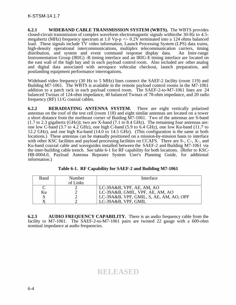
6.2.2 RERADIATING ANTENNA SYSTEM. There are eight vertically polarizedantennas on the roof of the test cell (room 118) and eight similar antennas are located on a towera short distance from the northeast corner of Buiding M7-1061. Two of the antennas are S-band(1.7 to 2.3 gigahertz (GHz)); two are X-band (7.1 to 8.4 GHz). The remaining four antennas are:one low C-band (3.7 to 4.2 GHz), one high C-band (5.9 to 6.4 GHz), one low Ku-band (11.7 to12.2 GHz), and one high Ku-band (14.0 to 14.5 GHz). (This configuration is the same at bothlocations.) These antennas can be manually positioned on a mission-by-mission basis to interfacewith other KSC facilities and payload processing facilities on CCAFS. There are S-, C-, X-, andKu-band coaxial cable and waveguides installed between the SAEF-2 and Building M7-1061 viathe inter-building cable trench. See table 6-1 for RF capability for both locations. (Refer to KSC-HB-0004.0, Payload Antenna Repeater System User's Planning Guide, for additionalinformation.)
Table 6-1. RF Capability for SAEF-2 and Building M7-1061
Band Number Interfaceof Links
C 2 LC-39A&B, VPF, AE, AM, AOKu 2 LC-39A&B, GMIL, VPF, AE, AM, AOS 2 LC-39A&B, VPF, GMIL, S, AE, AM, AO, OPFX 2 LC-39A&B, VPF, GMIL
6.2.3 AUDIO FREQUENCY CAPABILITY. There is an audio frequency cable from thefacility to M7-1061. The SAEF-2-to-M7-1061 pairs are twisted 22 gauge with a 600-ohmnominal impedance at audio frequencies.
RELEASED
6-4

K-STSM-14.1.7
SECTION VII
FACILITY DESCRIPTION SUMMARY, SAEF-2
7.1 SAFETY
a. Designated explosive safe area
b. Restriction - determined by NASA safety on a payload to payload basis
c. Exhaust system
d. Waste fuel vent, oxidizer vent, Krypton 85 vent - high bay (room 102)
7.2 FLOOR SPACE
Facility 1556.08 m² (16,750 ft²) of usable floor space
a. Airlock (room 101) 17.68 m by 12.50 m (58 ft long by 41 ft wide)
b. High bay (room 102) 30.18 m by 14.94 m (99 ft long by 49 ft wide)
c. Low bay (room 102A) 8.23 m by 5.79 m (27 ft long by 19 ft wide)
d. Low bay (room 102B) 21.95 m by 5.79 m (72 ft long by 19 ft wide)
e. Test cell (room 118) 11.28 m by 11.28 m (37 ft long by 37 ft wide)
f. Remote payload controlroom and support areas(M7-1061 addition) 483.08 m² (5200 ft²)
7.3 CEILING HEIGHTS
a. Airlock (room 101) 15.85 m (52 ft)
b. High bay (room 102) 22.56 m (74 ft)
c. Low bay (room 102A) 13.26 m (43 ft 6 in)
d. Low bay (room 102B) 7.62 m (25 ft)
e. Test cell (room 118) 15.85 m (52 ft)
RELEASED
7-1
K-STSM-14.1.7
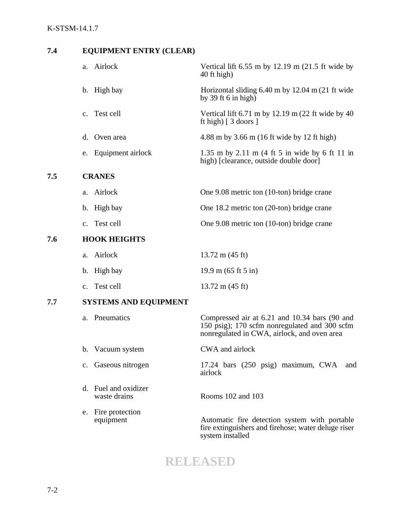
7.4 EQUIPMENT ENTRY (CLEAR)
a. Airlock Vertical lift 6.55 m by 12.19 m (21.5 ft wide by40 ft high)
b. High bay Horizontal sliding 6.40 m by 12.04 m (21 ft wideby 39 ft 6 in high)
c. Test cell Vertical lift 6.71 m by 12.19 m (22 ft wide by 40ft high) [ 3 doors ]
d. Oven area 4.88 m by 3.66 m (16 ft wide by 12 ft high)
e. Equipment airlock 1.35 m by 2.11 m (4 ft 5 in wide by 6 ft 11 inhigh) [clearance, outside double door]
7.5 CRANES
a. Airlock One 9.08 metric ton (10-ton) bridge crane
b. High bay One 18.2 metric ton (20-ton) bridge crane
c. Test cell One 9.08 metric ton (10-ton) bridge crane
7.6 HOOK HEIGHTS
a. Airlock 13.72 m (45 ft)
b. High bay 19.9 m (65 ft 5 in)
c. Test cell 13.72 m (45 ft)
7.7 SYSTEMS AND EQUIPMENT
a. Pneumatics Compressed air at 6.21 and 10.34 bars (90 and150 psig); 170 scfm nonregulated and 300 scfmnonregulated in CWA, airlock, and oven area
b. Vacuum system CWA and airlock
c. Gaseous nitrogen 17.24 bars (250 psig) maximum, CWA andairlock
d. Fuel and oxidizerwaste drains Rooms 102 and 103
e. Fire protectionequipment Automatic fire detection system with portable
fire extinguishers and firehose; water deluge risersystem installed
RELEASED
7-2
K-STSM-14.1.7
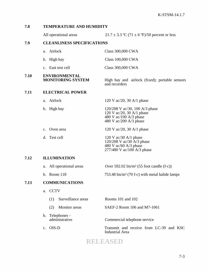
7.8 TEMPERATURE AND HUMIDITY
All operational areas 21.7 ± 3.3 ºC (71 ± 6 ºF)/50 percent or less
7.9 CLEANLINESS SPECIFICATIONS
a. Airlock Class 300,000 CWA
b. High bay Class 100,000 CWA
c. East test cell Class 300,000 CWA
7.10 ENVIRONMENTALMONITORING SYSTEM High bay and airlock (fixed); portable sensors
and recorders
7.11 ELECTRICAL POWER
a. Airlock 120 V ac/20, 30 A/1 phase
b. High bay 120/208 V ac/30, 100 A/3 phase120 V ac/20, 30 A/1 phase480 V ac/100 A/3 phase480 V ac/200 A/3 phase
c. Oven area 120 V ac/20, 30 A/1 phase
d. Test cell 120 V ac/30 A/1 phase120/208 V ac/30 A/3 phase480 V ac/60 A/3 phase277/480 V ac/100 A/3 phase
7.12 ILLUMINATION
a. All operational areas Over 592.02 lm/m² (55 foot candle (f-c))
b. Room 118 753.48 lm/m² (70 f-c) with metal halide lamps
7.13 COMMUNICATIONS
a. CCTV
(1) Surveillance areas Rooms 101 and 102
(2) Monitor areas SAEF-2 Room 106 and M7-1061
b. Telephones -administrative Commercial telephone service
c. OIS-D Transmit and receive from LC-39 and KSCIndustrial Area
RELEASED
7-3
K-STSM-14.1.7
d. Public address All SAEF-2 operational areas. Aural warningdevice overriding microphone input. Paging andarea warning system in all operational andsupport areas.
e. Countdown clocks Rooms 102, 106, and 118
7.14 DATA HANDLING
a. Wideband CableTransmission System
(1) Frequency 30 Hz to 4.5 MHz
(2) Capability TV video, telemetry, data display, LPS data,high density, OIS-D, automated payloadcheckout and surveillance monitoringinformation, multiplex telecommunicationscarriers, timing distribution (IRIG-B and IRIG-E), system and event command, and responsedisplay data
- Uplink and downlink RF OIS-D- CCTV- Payload command data- Payload telemetry- ESS CCTV and data- SAEF-2-to Communication Distribution andSwitching Center maintenance
b. Radiating system C-band to LC-39A&B, GMIL, VPF, AE, AM,AO, M7-1061Ku-band to LC-39A&B, GMIL, VPF, AE, AM,AO, M7-1061S-band to LC-39A&B, VPF, GMIL, S, AE,AM, AO, M7-1061, OPFX-band to LC-39A&B, VPF, GMIL, M7-1061
c. Audio system An audio cable to Building M7-1061
RELEASED
7-4

RELEASED