facilities infrastructure study mechanical systems for...
TRANSCRIPT
FACILITIES INFRASTRUCTURE STUDY
MECHANICAL SYSTEMS
For
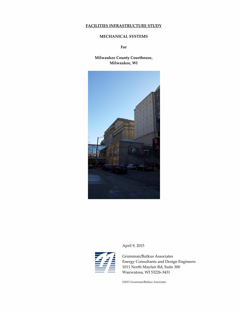
Milwaukee County Courthouse,
Milwaukee, WI
April 9, 2015
Grumman/Butkus Associates
Energy Consultants and Design Engineers
1011 North Mayfair Rd, Suite 300
Wauwatosa, WI 53226-3431
©2015 Grumman/Butkus Associates
Report Milwaukee County Courthouse
April 9th, 2015 Facility Survey
Page 2 G/BA #P15-0108
TABLE OF CONTENTS
Introduction .......................................................................................................................................................... 3
Executive Summary ............................................................................................................................................ 4
Equipment Conditon and Observations ........................................................................................................... 6
Main Air Handling Units (4): ........................................................................................................................ 6
Recommendations: ..................................................................................................................................... 6
Heating and Ventilation Units (3), Urn fans: .............................................................................................. 7
Recommendations: ..................................................................................................................................... 7
Computer room air conditioning units (CRAC) and Mini-Split Units: ................................................... 8
Recommendations: ..................................................................................................................................... 8
Exhaust Fans: ................................................................................................................................................... 9
Recommendations: ..................................................................................................................................... 9
Chilled Water and Steam Plant ........................................................................................................................ 10
Chillers and Cooling Towers: ..................................................................................................................... 10
Recommendations: ................................................................................................................................... 10
Pumps – chilled and condenser water pumps: ......................................................................................... 11
Recommendations: ................................................................................................................................... 11
Pumps – condensate pumps: ....................................................................................................................... 12
Recommendations: ................................................................................................................................... 12
Expected Service Lives ...................................................................................................................................... 13
Exhibits................................................................................................................................................................ 14
Report Milwaukee County Courthouse
April 9th, 2015 Facility Survey
Page 3 G/BA #P15-0108
INTRODUCTION
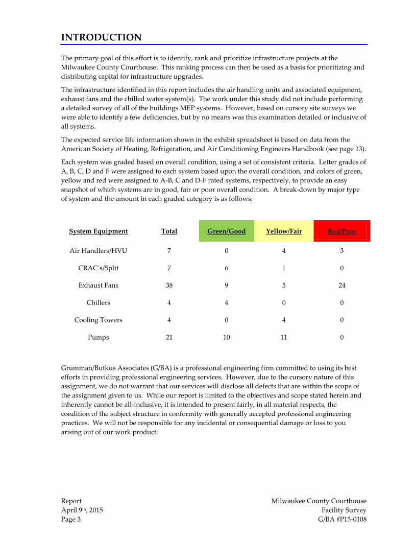
The primary goal of this effort is to identify, rank and prioritize infrastructure projects at the
Milwaukee County Courthouse. This ranking process can then be used as a basis for prioritizing and
distributing capital for infrastructure upgrades.
The infrastructure identified in this report includes the air handling units and associated equipment,
exhaust fans and the chilled water system(s). The work under this study did not include performing
a detailed survey of all of the buildings MEP systems. However, based on cursory site surveys we
were able to identify a few deficiencies, but by no means was this examination detailed or inclusive of
all systems.
The expected service life information shown in the exhibit spreadsheet is based on data from the
American Society of Heating, Refrigeration, and Air Conditioning Engineers Handbook (see page 13).
Each system was graded based on overall condition, using a set of consistent criteria. Letter grades of
A, B, C, D and F were assigned to each system based upon the overall condition, and colors of green,
yellow and red were assigned to A-B, C and D-F rated systems, respectively, to provide an easy
snapshot of which systems are in good, fair or poor overall condition. A break-down by major type
of system and the amount in each graded category is as follows:
System Equipment Total Green/Good Yellow/Fair Red/Poor
Air Handlers/HVU 7 0 4 3
CRAC’s/Split 7 6 1 0
Exhaust Fans 38 9 5 24
Chillers 4 4 0 0
Cooling Towers 4 0 4 0
Pumps 21 10 11 0
Grumman/Butkus Associates (G/BA) is a professional engineering firm committed to using its best
efforts in providing professional engineering services. However, due to the cursory nature of this
assignment, we do not warrant that our services will disclose all defects that are within the scope of
the assignment given to us. While our report is limited to the objectives and scope stated herein and
inherently cannot be all-inclusive, it is intended to present fairly, in all material respects, the
condition of the subject structure in conformity with generally accepted professional engineering
practices. We will not be responsible for any incidental or consequential damage or loss to you
arising out of our work product.
Report Milwaukee County Courthouse
April 9th, 2015 Facility Survey
Page 4 G/BA #P15-0108
EXECUTIVE SUMMARY
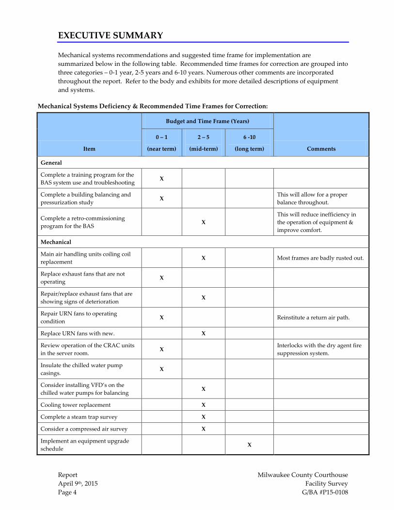
Mechanical systems recommendations and suggested time frame for implementation are
summarized below in the following table. Recommended time frames for correction are grouped into
three categories – 0-1 year, 2-5 years and 6-10 years. Numerous other comments are incorporated
throughout the report. Refer to the body and exhibits for more detailed descriptions of equipment
and systems.
Mechanical Systems Deficiency & Recommended Time Frames for Correction:
Item
Budget and Time Frame (Years)
Comments
0 – 1
(near term)
2 – 5
(mid-term)
6 -10
(long term)
General
Complete a training program for the
BAS system use and troubleshooting X
Complete a building balancing and
pressurization study X
This will allow for a proper
balance throughout.
Complete a retro-commissioning
program for the BAS X
This will reduce inefficiency in
the operation of equipment &
improve comfort.
Mechanical
Main air handling units coiling coil
replacement X Most frames are badly rusted out.
Replace exhaust fans that are not
operating X
Repair/replace exhaust fans that are
showing signs of deterioration X
Repair URN fans to operating
condition X Reinstitute a return air path.
Replace URN fans with new. X
Review operation of the CRAC units
in the server room. X
Interlocks with the dry agent fire
suppression system.
Insulate the chilled water pump
casings. X
Consider installing VFD’s on the
chilled water pumps for balancing X
Cooling tower replacement X
Complete a steam trap survey X
Consider a compressed air survey X
Implement an equipment upgrade
schedule X

Report Milwaukee County Courthouse
April 9th, 2015 Facility Survey
Page 5 G/BA #P15-0108
G/BA recommends the following top five mechanical issues to be addressed:
Based on our site survey the following mechanical projects from those listed on the previous page are
recommended to be undertaken in order of importance:
1. Repair cooling tower damage prior to the cooling season.
2. Replace non-functioning exhaust fans and repair others to avoid failures.
3. Re-institute the return air paths for the URN fans, start a design for replacements units.
4. Implement a schedule for the cooling coils replacement in the four (4) main air handling
units.
5. Complete a building pressurization analysis, with a retro commissioning of the control
systems to identify any airflow and control operation deficiencies.
a. Resolve key issues with repairs and replacements.
Other considerations for projects are as follows:
1. Label piping with flow direction arrows and service type.
2. Perform retro-commissioning to identify any control issues.
3. Continue a mechanical assessment of VAV boxes.
4. Consider a steam and condensate pipe study to implement control valves, rather than
manual valves for comfort control.
a. There was indication of numerous leaks in system from facility personnel.
5. Implement a computer maintenance management system for equipment / system work order
tracking.
Report Milwaukee County Courthouse
April 9th, 2015 Facility Survey
Page 6 G/BA #P15-0108
EQUIPMENT CONDITON AND OBSERVATIONS
Main Air Handling Units (4):
There are four main custom built-up air handling units that are used to heat, cool and ventilate the
courthouse. Each unit serves a quadrant through a dual duct system and VAV boxes. The main
components of these units consist of a return fan, filters, supply fan, chilled water cooling coil and a
steam heating coil. The distribution ductwork is routed thru the various light courts prior to entering
the buildings on the respective floors.
SA-1 and SA-2 are located on the 8th floor of the building. The dampers are showing signs of age and
do not close completely, thus allowing outside elements into the plenum and damage the floors. For
the most part the components were in good shape, other than the cooling coils. The frames for the
coils are rusted out with holes throughout. Only one (AC-1) steam coil appeared to have signs of a
leak. SA-1 and SA-2 cooling coil drain lines appeared to be undersized or the traps are not sized
properly, causing standing condensate inside the unit. SA-2 cooling coil has a couple of patches from
a prior repair. Braces between SA-1 (discharge side of supply fan section) and the north wall were
witnessed. Is there an issue with the air handling unit casing that requires bracing?
AC-3 and AC-4 are accessed from the ground floor and located in light courts. The outside air intake
is located on the roof of the air handling units and the relief is ducted to above the roof line. This
arrangement draws fresh air down the light court to the air handling unit. Access around the units
outside is difficult due to the amount of debris and bird droppings, and should be cleaned. AC-3 and
AC-4 have commercial ceiling fans installed in the plenum. These fans were installed to circulate the
warm air in the plenum that results from the heating coil control valve going 100% open when the
fans are off.
New VFD’s were installed on the supply and return fans of air handling units, with only one motor
being equipped with AEGIS rings to dissipate any stray current that may discharge through the
bearings.
Recommendations:
1. These units are on a night set back schedule from 6 pm to 6am, an optimal start program
may assist in the comfort of the building.
2. A program change to regulate the MAT to a set value, rather than have the heating valve go
100% open when off.
3. Replace the cooling coils in the units.
4. Increase the size of the condensate drain for cooling in SA-1 and SA-2.
5. Remove any vegetation from the insulation. Inspect surrounding insulation and repairs as
needed.
6. Visually inspect duct work for any leaks and repair as found. (leaks were heard while the
survey was conducted)
7. Investigate bracing of air handling unit casing to north wall.
8. Review the operation and maintenance manuals for preventative maintenance program.
Report Milwaukee County Courthouse
April 9th, 2015 Facility Survey
Page 7 G/BA #P15-0108
Heating and Ventilation Units (3), Urn fans:
There are three smaller units that appear to be for ventilation and comfort conditioning of the main
entrances. One serves the 10th street entrance (HVU-9) and two serve the east side entrances of
MacArthur Square. One serves the north end (HVU-8) and one serves the south end (HVU-7). These
are single skin units with steam coils with no fins and a face-bypass damper. Newer VFD’s and
motors are installed on the units. The filters are a 30% filter media with no great filtration properties.
HVU-7, located off the 9th street tunnel is currently turned off at the VFD due to comfort complaints
of overheating. The steam is still on to the 4 coils. HVU-8 is identical to HVU-7 and located in the
paint shop. The steam is isolation valve is closed and the motor disconnect is off and does not appear
to have been operational in awhile.
HVU-9 is located near the new substation in the basement. It has similar components to HVU-7 and
8.
While each unit has a return air path, HVU-7 and 8 have had their return ductwork cut off (see
pictures). These units now return air from the location where they sit. The block wall opening where
the return path was has been has been bricked over. The location of current pipe and duct suggests
that these duct paths have been gone for awhile. Existing return grilles are seen in the entrance
vestibules, however no air movement can be felt through them. The lack of a proper return air to
these units will affect their operation.
HVU-9 draws return air from the electrical vault in the basement and transfer this air to the west
entrance vestibule. A return duct is present on top of the unit, yet no path could be found from the
ground level or any return grilles.
All of these units discharge their air through large Urns in the vestibules. It appears that there is a
concern for the filtration, as the Urns have a 4” filter duct taped to the top of these urns.
Recommendations:
1. Establish a return path to the units to allow for proper operation.
2. Change out filter rack with a MERV 8 pleated filter.
3. Design and install new efficient units.
4. Review operation and maintenance manuals for preventative maintenance program.
Report Milwaukee County Courthouse
April 9th, 2015 Facility Survey
Page 8 G/BA #P15-0108
Computer room air conditioning units (CRAC) and Mini-Split Units:
On the ground level in room G2A, there is one floor mount CRAC and four mini-split systems. Their
respective condensing units are located in the light court to the south of the room on the same level.
Access to the condensing units is through a window in the G1 maintenance offices. These
condensing units need to be regularly cleaned due to the amount of feathers/dirt build up.
The floor mounted unit is manufactured by Liebert and is a typical stand up unit. It is in good
condition and appears to be maintained. Control may be via a return air sensor inside the unit and
thru the onboard controls. The BAS shows this unit interfaces thru the DDC control system for
alarms and temperatures.
The four (4) Mitsubishi mini-split units are ceiling hung and controlled by their individual
thermostats. These units do not appear on the BAS; therefore no alarms will be present if these fail.
All these units appear to be newer and in good condition.
The room has a drop ceiling and has a supply grille and return diffuser from its corresponding
quadrant SA-1 unit. This may be for pressurization and ventilation. However, there is also a clean
agent fire suppression system in this room. It is unclear whether there are any dampers or control
system functions to shut down units and stop air flow in the event of a release.
A newer UPS room is located in the basement and served by a newer Trane mini-split system. Its
condensing unit is located in the light court above. The room has supply and return ducted to the
mini-split. A large opening exists in the ceiling of the UPS room, allowing cool air to escape from the
room.
A small room is located on the 9th floor (roof) containing communication equipment. A small mini-
split system serves this room and is in fair condition. The room is heated in the cold months via a
steam radiator.
Recommendations:
1. Incorporate an alarm point to the BAS system for the four mini-split systems to indicate a
failure.
2. Investigate the controls in place in the event of a dry agent fire suppression system release.
Verify that the room is isolated to contain the suppression gas when it is released.
3. Seal up the hole in the UPS room ceiling to aid in maintaining a clean cool environment for
the UPS system.
4. Review operation and maintenance manuals for preventative maintenance program.
Report Milwaukee County Courthouse
April 9th, 2015 Facility Survey
Page 9 G/BA #P15-0108
Exhaust Fans:
Areas served by exhaust fans were not verified using existing drawings or visually, however some
appear to be serving bathroom exhaust risers. Most fans had a local disconnect or motor switch at
the fan. Any remote breakers were not traced, therefore we were not able to determine whether these
had tripped on overload if the fans were found not running. The majority of fans were not marked
with any sort of identifying marks, therefore we were unable to correlate these back to the BAS
system. Those that had labels are assumed to be correct.
As noted in the exhaust fan condition letter dated March 12th, 2015. (exhibit 1) ten (10) fans were
running, seven (7) had their motors running with the belts broken, eight (8) were not running at all
and three (3) were running, but the belts were poorly fitting/stretched and barely turning the fan.
The next site visit ten more fans were found. Of these, six (6) were running and four (4) were not
running.
The fans were found to be either in fair condition given their age, or poorly neglected, rusted and
seized. Of the fans not running, their conditions varied from rusted out motors, seized fan shafts to
broken backdraft dampers.
The kitchen has four (4) exhaust fans on the roof in the light court; two appeared to serve a hood of
some sort. These two fans were extremely greasy, posing the question of when they were
professionally cleaned to prevent the buildup of grease. One fan was found off due to a seized
motor. It was unclear as to the use of area it serves.
A single exhaust fan was found outside a 3rd floor window and served a single grille in a room on the
2nd floor. This room is now office/file storage. Occupants indicated that at times a noise comes from
the grille and occasionally water is observed dripping from the grille.
The BAS has twenty-two (22) exhaust fans listed on a screen. All showed their start/stop command as
on, yet nine (9) showed status as off.
Recommendations:
1. Repair / replace any non-running units.
2. Overhaul existing running fans.
3. Label all exhaust fans, and create a floor plan or location chart of units as well as investigate
the current use of all fans.
4. Consolidate fan belt sizes to reduce inventory.
5. Contract a company that is dedicated to inspection and cleaning the kitchen exhaust fans
(and duct work) as dictated by Section 609 of the international Fire Code and NFPA 96.
6. Review operation and maintenance manuals for preventative maintenance program.
Report Milwaukee County Courthouse
April 9th, 2015 Facility Survey
Page 10 G/BA #P15-0108
CHILLED WATER AND STEAM PLANT
Chillers and Cooling Towers:
The courthouse penthouse (8th floor) has four (4) Trane centrifugal chillers each served with an
individual cooling tower. These chillers serve a primary/secondary chilled water system that supplies
chilled water to each of the four (4) large air handling unit pumps within the penthouse.
Each of the chillers is in good condition and facility staff indicates that their condensers tubes are
cleaned out on a regular basis. Some of the armaflex insulation on the chillers appears to be
deteriorating and should be monitored to avoid any uninsulated rusting. All four chillers had their
electrical panel unlocked and open; this should be avoided to prevent any electrical shock to
personnel not trained. Chiller #1 had some discrepancies in labeling of flow through the pipes and
should be relabeled.
As mentioned in an email sent March 10, 2015 (exhibit 2) to Milwaukee County.
Cooling towers 1 and 2 have the following conditions:
Interior coating has lost adhesion to the tower surface and is bubbling away from the tower.
Penetration of water could result in rusting of the walls/floors. Coils and fan blades are dirty as there
is also debris and scale build up on the bottom of the towers. The frames of the towers have rust
showing through the paint.
Cooling towers 3 and 4 have the following conditions:
Damaged pneumatic sensors for level control, dirty coils and fan blades, debris and scale build up
inside the towers. Tower #3 has some interior coating missing is badly rusting in these areas.
Recommendations:
1. Clean any debris and wash the fan blades.
2. Repair the level transmitters on CT-3 and 4.
3. Replace the belts on all fans, remove excessive grease from motors.
4. Repair CT-3 coating.
5. Repair CT-1 and 2 bubbling on coating.
6. Scrape and paint the frame work of the cooling towers.
7. Review operation and maintenance manuals for preventative maintenance program.
Report Milwaukee County Courthouse
April 9th, 2015 Facility Survey
Page 11 G/BA #P15-0108
Pumps – Chilled and Condenser Water Pumps:
Each of the chillers has primary chilled water and a condenser water pump. The secondary system
consists of three (3) chilled water pumps. Pumps 1 and 3 are sized equally and pump 2 is half the size
of the others. All these pumps are constant volume that operated based on how many chillers are
online. One point to note is that doesn’t appear to be a balance valve on the pumps.
The general condition of these units is good. There appears to be over greasing of bearings as
evidenced by the visual globs of grease below each bearing cap on the base. The motor vents are
blocked with dirt and grease, thus inhibiting the flow of air through the motor. The piping is well
insulated throughout the system up to the first flange of the pump. Because the pumps themselves
are not insulated, rust has started to appear on the casings due to sweating in the summer months
while the system is on. A couple of the pumps appear to have a pressure switch that is not piped into
the system. Is this a safety switch or is it a differential pressure switch used for status?
Each of the four main air handling units have a dedicated pump with a set of chilled water control
valves located in the penthouse. The insulation around the valves indicate that at some time these
valves had packing leaks, with one control valve for SA-4 having a funnel in place to collect water.
Recommendations:
1. Insulate the chilled water casings to prevent further sweating and rusting.
2. Clean out vents on the motors and inspect to ensure no damage.
3. Scrape and paint the drain pans and frames that are showing signs or rust.
4. Consider retrofitting the pump motors with a VFD to aid in balancing the system.
a. Incorporate programming in the BAS for this as well.
5. Review operation and maintenance manuals for preventative maintenance program.
Report Milwaukee County Courthouse
April 9th, 2015 Facility Survey
Page 12 G/BA #P15-0108
Pumps – Condensate Pumps:
SA-1 and SA-2 have new steam condensate pumps (circa 2014) in their respective penthouse. Each of
these units pumps condensate to a Trane unit heater (UH) located along the outer wall. When the
Aquastat sensor (set at 160°F) in the discharge pipe of the UH is tripped, the fan turns on to cool the
condensate. The condensate then sits in an overflow tank until more is added and overflows to a
floor drain nearby. A strap on Aquastat set at 110°F is located on the overflow pipe of the storage
tank and is connected to the BAS to issue an alarm. If too hot, a manual hose bib is opened to cool the
condensate as it goes down the drain. This hose is typically regulated by hand and left on at all
times, whether the condensate is flowing or not.
AC-3 and AC-4 condensate drains to the basement duplex receiver and pump. At the time of survey,
this unit was tripped out and overflowing to the floor and local floor drain. The discharge of this
pump is to the main condensate vacuum system located in room B27.
Each of the Urn fans (HVU-7, 8 & 9) have dedicated duplex receivers and pumps and appear to be in
fair condition.
The main vacuum-condensate pump system draws back condensate from the perimeter heating
system. A second vacuum-pump appears to isolated and abandoned in place. The discharge of this
system is to a large receiver in the same room. This receiver has two inline pumps which then
discharges the condensate to a storm drain conductor. A third small inline pump located on the side
of the receiver circulates hot condensate thru a small plate and frame heat exchanger meant to
transfer heat to the domestic hot water system. This pump is off and the lines are isolated.
The domestic hot water side of the heat exchange circulates domestic hot water with a small inline
pump thru the plate and frame heat exchanger. This is off and isolated as well. T he domestic hot
water tank is supplemented with a steam tube bundle inside the tank.
Recommendations:
1. Reinstitute the condensate to domestic hot water heat recovery system to recover heat from
the condensate.
2. Consider adding a solenoid valve connected to the strap on Aquastat on the discharge line of
the condensate overflow tank to open only when the temperature is too hot for condensate to
go down the drain.
3. Consider rebuilding the secondary vacuum-condensate pump system as a backup.
4. Review operation and maintenance manuals for preventative maintenance program.
Report Milwaukee County Courthouse
April 9th, 2015 Facility Survey
Page 13 G/BA #P15-0108
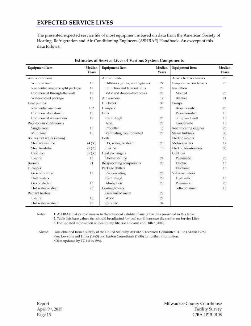
EXPECTED SERVICE LIVES
The presented expected service life of most equipment is based on data from the American Society of
Heating, Refrigeration and Air-Conditioning Engineers (ASHRAE) Handbook. An excerpt of this
data follows:
Estimates of Service Lives of Various System Components Equipment Item
Median
Years
Equipment Item
Median
Years
Equipment Item
Median
Years
Air conditioners Air terminals Air-cooled condensers 20
Window unit 10 Diffusers, grilles, and registers 27 Evaporative condensers 20
Residential single or split package 15 Induction and fan-coil units 20 Insulation
Commercial through-the-wall 15 VAV and double-duct boxes 20 Molded 20
Water-cooled package 15 Air washers 17 Blanket 24
Heat pumps Ductwork 30 Pumps
Residential air-to-air 15 b Dampers 20 Base-mounted 20
Commercial air-to-air 15 Fans Pipe-mounted 10
Commercial water-to-air 19 Centrifugal 25 Sump and well 10
Roof-top air conditioners Axial 20 Condensate 15
Single-zone 15 Propeller 15 Reciprocating engines 20
Multizone 15 Ventilating roof-mounted 20 Steam turbines 30
Boilers, hot water (steam) Coils Electric motors 18
Steel water-tube 24 (30) DX, water, or steam 20 Motor starters 17
Steel fire-tube 25 (25) Electric 15 Electric transformers 30
Cast iron 35 (30) Heat exchangers Controls
Electric 15 Shell-and-tube 24 Pneumatic 20
Burners 21 Reciprocating compressors 20 Electric 16
Furnaces Package chillers Electronic 15
Gas- or oil-fired 18 Reciprocating 20 Valve actuators
Unit heaters Centrifugal 23 Hydraulic 15
Gas or electric 13 Absorption 23 Pneumatic 20
Hot water or steam 20 Cooling towers Self-contained 10
Radiant heaters Galvanized metal 20
Electric 10 Wood 20
Hot water or steam 25 Ceramic 34
Notes: 1. ASHRAE makes no claims as to the statistical validity of any of the data presented in this table.
2. Table lists base values that should be adjusted for local conditions (see the section on Service Life).
3. For updated information on heat pump life, see Lovvorn and Hiller (2002).
Source: Data obtained from a survey of the United States by ASHRAE Technical Committee TC 1.8 (Akalin 1978).
a See Lovvorn and Hiller (1985) and Easton Consultants (1986) for further information.
b Data updated by TC 1.8 in 1986.
Report Milwaukee County Courthouse
April 9th, 2015 Facility Survey
Page 14 G/BA #P15-0108
EXHIBITS
The following exhibits are:
1. Exhibit 1 – Exhaust fan condition letter.
2. Exhibit 2 – Cooling tower condition letter.
3. Exhibit 3 - Facility Assessment Data – AHU / HVU / CRAC’s
4. Exhibit 4 – Facility Assessment Data – Exhaust Fans
5. Exhibit 5 – Facility Assessment Data – Chilled Water and Steam Plant
6. Exhibit 6 – Building Description
See CD for individual assessment checklists and supporting pictures.