facility requirements - city of goleta
TRANSCRIPT

Now that existing capacities and projected demands have been established, this data can be translated into the speci ic types and quantities of facilities that can adequately serve projected demand levels. This chapter determines air ield (i.e., runways, taxiways, navigational aids, marking and lighting, and support facilities), and landside (i.e., passenger terminal building, cargo buildings, general aviation terminal facilities, hangars, aircraft parking apron, support facilities) facility requirements based on the analysis done in Chapters Two and Three.
The objective of this effort is to identify, in general terms, the adequacy of the existing Airport facilities, outline what new facilities may be needed, and when they may be needed to accommodate forecast demands. Having established these facility requirements, alternatives for providing
the facilities will be evaluated in Chapter Five to determine the most reasonable and feasible means for implementation.
AIRFIELD REQUIREMENTS
The analyses of the operational capacity and the critical design aircraft are used to determine air ield needs. This includes runway con iguration, dimensional standards, pavement strength, as well as navigational aids, lighting, and marking. As was previously discussed in Chapter Two, the air ield and primary Runway 7-25 should be planned to accommodate at least ARC D-III design standards.
RUNWAY CONFIGURATION
Key considerations in the runway con iguration of an airport involve the orientation for wind coverage and the operation-
4-1
D R A F T F I N A LA I R P O R T M A S T E R P L A N
FACILITY REQUIREMENTSCHAPTER FOUR
AA

DRAFT FINAL 4-2
al capacity of the runway system. FAA Advisory Circular 150/5300-13, Airport Design, recommends that a crosswind runway should be made available when the primary runway orientation provides less than 95 percent wind coverage for any aircraft forecast to use the airport on a regular basis. The 95 percent wind coverage is comput-ed on the basis of the crosswind compo-nent not exceeding 10.5 knots (12 mph) for ARC A-I and B-I; 13 knots (15 mph) for ARC A-II and B-II; and 16 knots (18 mph) for ARC A-III, B-III, and C-I through D-II; and 20 knots (23 mph) for ARC C-III through D-IV. A wind rose is a tool used to calculate the wind coverage of an airport. The all-weather wind rose for Santa Barbara Air-port is presented on Exhibit 4A. The ori-entation of Runway 7-25 provides 98.7 percent coverage for 10.5 knot cross-winds, and coverage for the higher design crosswinds is over 99 percent. The crosswind runways provide 96.2 percent coverage for 10.5 knot crosswinds and greater than 97 percent coverage for the higher design crosswinds. Thus, the pri-mary and crosswind runways at the Air-port provide adequate wind coverage for all aircraft types. According to FAA Order 5090.3C, Field Formulation of the National Plan of Inte-grated Airport Systems (NPIAS), capacity development should be recommended when activity approaches the 60 percent level. This is an approximate level to begin the detailed planning of capacity improvements. Actual implementation may be deferred until such time that the improvement is considered timely and cost-beneficial. The earlier airfield capac-ity analysis conducted in Chapter Three indicated that, in 2011, the airfield was operating at 48 percent of its annual ser-
vice volume (ASV) and will not reach its ASV by the long term planning horizon. As a result, no major capacity improve-ment projects, such as the construction of a new runway, will be necessary. RUNWAY DIMENSIONAL REQUIREMENTS Runway dimensional standards include the length and width of the runway, as well as the dimensions associated with runway safety areas and other clearances. These requirements are based upon the design aircraft, or group of aircraft. The runway length must consider the perfor-mance characteristics of individual air-craft types, while the other dimensional standards are generally based upon the most critical ARC expected to use the runway. The dimensional standards are outlined for the planning period for the primary runway, as well as for the paral-lel crosswind runways, to meet future ca-pacity demand. Runway Length The aircraft performance capability is a key factor in determining the runway length needed for takeoff and landing. The performance capability and, subse-quently, the runway length requirement of a given aircraft type can be affected by the elevation of the airport, the air tem-perature, the gradient of the runway, and the operating weight of the aircraft. Air-craft performance declines as each of these factors increase. The airport elevation at Santa Barbara Airport is 13 feet above mean sea level (MSL). The temperature commonly used for design is the mean maximum daily temperature during the hottest month.

Exhibit 4AWINDROSE

DRAFT FINAL 4-3
According to the National Climatic Data Center, that is 74.9 degrees Fahrenheit (F) at the Airport during the months of August and September. The change in el-evation (gradient) varies only slightly along primary Runway 7-25 and there-fore does not factor when calculating runway length requirements. The Airport should have the capability to handle the most demanding aircraft with regards to runway length. Thus, the fol-lowing discussion considers the most de-manding runway length requirements now and in the future. The aircraft load is dependent upon the payload of passengers and/or cargo, plus the amount of fuel it has on board. For departures, the amount of fuel varies de-pending upon the length of non-stop flight or trip length. As of May 2012, the long-est daily non-stop commercial flights were to Denver (794.0 nautical miles) and Seattle (789.3 nautical miles). United Air-lines and Frontier Airlines both operate to Denver. United operates a 50-seat CRJ aircraft and Frontier Airlines operates a 99-seat Embraer 190. The Seattle flight is operated by a 70-seat CRJ 700 aircraft. According to recorded flight plans for 2011 accessed at AirportIQ.com, corpo-rate jet aircraft regularly conduct opera-tions to east coast destinations such as Teterboro (2,183.8 nautical miles), Phila-delphia (2,135.5 nautical miles), and Ft. Lauderdale (2,103.1 nautical miles). Air-craft conducting these trips include the Bombardier Global Express, Gulfstream II, and Gulfstream G500 business jet aircraft. Table 4A outlines the weight restrictions for key commercial and corporate jet air-craft to operate on Runway 7-25 at its current length of 6,052 feet at the Air-port’s design temperature and elevation.
As shown in the table, all but two of the aircraft can operate on Runway 7-25 at 90 percent useful load or greater. The Embraer 190 and CRJ 900 are weight re-stricted on Runway 7-25 with useful loads of 88 percent. Considering the non-stop commercial destinations currently being served and potential future non-stop routes such as Chicago (1,600 nm) and Dallas (1,150 nm), the commercial air-craft analyzed are capable of serving these destinations with current weight restricted useful loads. The corporate jet aircraft, with useful loads over 90 percent are also capable of serving long-range destinations on the east coast. FAA recommended runway length re-quirements for 75 percent and 100 per-cent of the corporate jet fleet weighing less than 60,000 pounds is summarized in Table 4B. As shown in the table, the FAA recommends a runway length of 7,100 feet for 100 percent of these aircraft at 90 percent useful load. However, the aircraft included in the FAA’s calculation include older model corporate jets that require long takeoff runway lengths, which are gradually being phased out of the national active fleet mix. Runway 7-25’s length of 6,052 feet is ad-equate for the commercial and corporate jets anticipated to use the Airport through the planning period and should therefore be maintained at its current length. According to FAA AC 150/5325-4B Run-way Length Requirements for Airport De-sign, crosswind runways should be de-signed for the lower crosswind capable aircraft using the primary runway. In the case of Santa Barbara Airport, the majori-ty of aircraft that utilize the crosswind runways are exclusively small general aviation aircraft weighing less than 12,500 pounds. The recommended run-way lengths for these small airplanes, as

DRAFT FINAL 4-4
calculated utilizing the runway length curve charts in AC 150/5325-4B, are out-lined in Table 4B. As shown in the table, the existing run-way lengths of Runway 15R-33L (4,184
ft.) and Runway 15L-33R (4,178 ft.) ex-ceed the FAA recommended runway lengths for the aircraft that utilize the crosswind runways. Therefore, the exist-ing runway lengths should be maintained through the planning period.
TABLE 4A Runway 7-25 Takeoff Weight Limits Santa Barbara Airport Runway 7-25 Limits
Aircraft Maximum
Takeoff Weight (lbs.) Maximum Useful
Load (lbs.) Takeoff Weight
(lbs.) Useful Load
(lbs.) %
Useful Load COMMERCIAL AIRCRAFT B737-700 154,500 70,400 154,500 70,400 100% Embraer 190 105,359 43,459 100,200 38,300 88% Embraer 170 79,344 32,744 79,344 32,744 100% CRJ 900 82,500 35,250 78,300 31,050 88% CRJ 700 72,750 29,250 72,750 29,250 100% Q400 64,500 26,614 64,500 26,614 100% CORPORATE JET AIRCRAFT Global Express XRS 99,500 49,750 95,000 45,250 91% Gulfstream G550 91,000 42,700 90,700 42,400 99% Gulfstream G450 73,900 30,900 73,900 30,900 100% Gulfstream G200 35,450 16,250 34,500 15,300 94% Current Runway 7-25 length – 6,052 ft. Design Criteria: Elevation – 13 ft. MSL; Temperature – 74.9F. Source: Coffman Associates analysis
TABLE 4B Small Airplane Runway Length Analysis Santa Barbara Airport
AIRPORT AND RUNWAY DATA Airport elevation ........................................................................................................................................................................................... 13 feet Mean daily maximum temperature ........................................................................................................................................................ 74.9 F
RUNWAY LENGTHS RECOMMENDED FOR AIRPORT DESIGN Small airplanes with less than 10 passenger seats 95 percent of these small airplanes ..................................................................................................................................... 3,100 feet 100 percent of these small airplanes ................................................................................................................................... 3,600 feet Small airplanes with 10 or more passenger seats ................................................................................................................... 3,900 feet Large airplanes of 60,000 pounds or less 75 percent or these large airplanes at 60 percent useful load ............................................................................... 4,550 feet 75 percent of these large airplanes at 90 percent useful load .................................................................................. 5,800 feet 100 percent of these large airplanes at 60 percent useful load ............................................................................... 4,950 feet 100 percent of these large airplanes at 90 percent useful load ............................................................................... 7,100 feet Reference: AC 150/5325-4B, Runway Length Requirements for Airport Design. Current Runway 7-25 Length – 6,052 ft. Current Runway 15R-33L length – 4,184 ft. Current Runway 15L-33R length – 4,178 ft. Source: Coffman Associates analysis.

DRAFT FINAL 4-5
Runway Design Standards Runway design standards define the widths and clearances required to opti-mize safe operations in the landing and takeoff area. These dimensional stand-ards can vary depending upon the ARC for each runway. Table 4C outlines key de-sign standards for the airport reference codes most applicable to Santa Barbara Airport presently and through the plan-ning period. As indicated in Chapter Two, the ARC for the Airport as established by the previous Aviation Facilities Plan is ARC C-III. As a result, the airfield facilities affiliated with the primary runway have been designed to meet ARC C-III design standards. The analysis of operations by ARC indicated that category ARC D-III should be considered the Airport’s critical design category. Ultimately, a change in approach category from C to D will not affect the current design of airfield facili-ties as the design standards for approach categories C and D at the Airport’s eleva-tion are identical. The runway centerline to holding position is the only criterion
that has an adjustment from approach category C to D; however, it only applies at airports with elevations above 100 feet (SBA is at 13 feet MSL). Presently, the air-field meets or exceeds the key ARC C/D-III airfield design standards. Design standards for the crosswind run-ways are also shown on Table 4C. As in-dicated, the only design standard not presently met is the 700-foot separation distance between the parallel runways (currently separated by 362 feet). The 700-foot distance is required for simulta-neous landings and takeoffs using visual flight rules (VFR). Since the crosswind parallel runways do not meet this design standard, simultaneous operations by all aircraft categories are not recommended. However, according to FAA AC 150/5060-5 Airport Capacity and Delay, simultane-ous operations are permitted with run-way separation distances of at least 300 feet if the runways are used exclusively by Category A aircraft.

DRAFT FINAL 4-6
TABLE 4C Airfield Design Standards Santa Barbara Airport Airport Reference Code
Design Standard
Runway 7-25 Current C-III (ft.)
Runway 7-25 Ultimate D-III (ft.)
Crosswind Runways
B-I (Small Airplane Exclusive) (ft.)
RUNWAYS Runway Length Runway Width
6,052 150
6,052 150
4,184/4,178 100/75
Runway Shoulder Width 25 25 10 Runway Safety Area Width Length Beyond End
500
1,000
500
1,000
120 240
Runway Object Free Area Width Length Beyond End
800
1,000
800
1,000
250 240
Runway Obstacle Free Zone Width Length Beyond End Precision Obstacle Free Zone Width Length Beyond End
400 200
800 200
400 200
800 200
400 200
N/A N/A
Runway Blast Pad Width Length
200 200
200 200
80 60
Runway Centerline to: Holding Position Parallel Taxiway Parallel Runway
250 400 700
250 400 700
125 150 700
TAXIWAYS Taxiway Width 50 50 25 Taxiway Safety Area Width Taxiway Object Free Area Width
118 186
118 186
49 89
Taxiway Centerline to: Fixed or Movable Object Parallel Taxiway/Taxilane
93
152
93
152
44.5 69
Taxilane Centerline to: Fixed or Movable Object Parallel Taxilane
81
140
81
140
39.5 64
RUNWAY PROTECTION ZONES Category I Inner Width Length Outer Width
1,000 2,500 1,750
1,000 2,500 1,750
NA NA NA
Visual and not lower than one-mile Inner Width Length Outer Width
500 1,700 1,010
500 1,700 1,010
250 1,000
450 Boldface indicates standard not met by current conditions. N/A – Not Applicable Source: FAA Advisory Circular 150/5300-13, Airport Design, Change 18
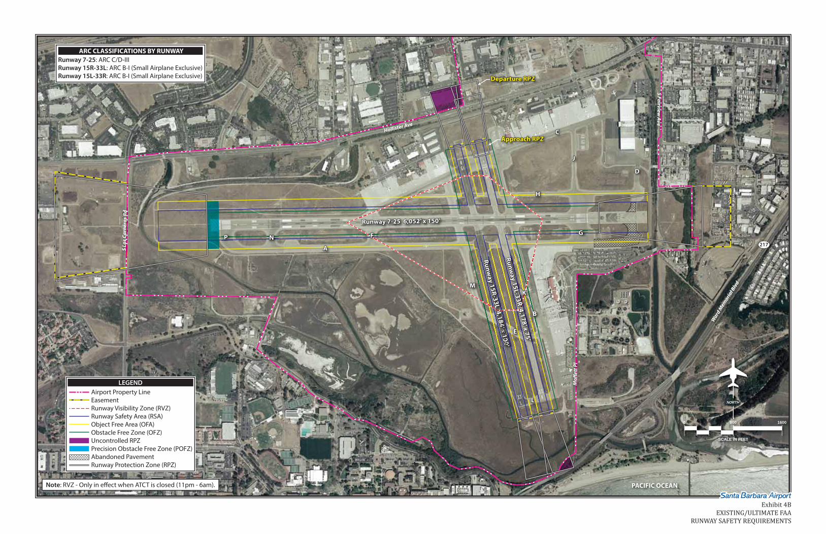
Exhibit 4B depicts the ARC C/D-III FAA design requirements for the runway safe-ty area (RSA), object free area (OFA), ob-stacle free zone (OFZ), and the runway
protection zones (RPZs) for Runway 7-25 and the ARC B-I (small airplanes exclu-sively) design requirements on Runways 15R-33L and 15L-33R. The RPZs for
NORTHRTNORTH
Runway 7-25 6,052’ x 150’Runway 7-25 6,052’ x 150’
Runway 15R-33L 4,184’ x 100’
184’x 100’0
14’x 100’
184’x 100’Runw
ay 15L-33R 4,178’ x 75’
PACIFIC OCEAN
S Lo
s Car
nero
s Rd
Moff
ett P
l
Hollister Ave
S Fairview Ave
217
Ward
Mem
orial B
lvd
HH
CC
AA
MM
PP NN FF GG
DD
JJ
EE
BB3333 KK
LL
LEGENDAirport Property LineEasementRunway Visibility Zone (RVZ)Runway Safety Area (RSA)Object Free Area (OFA)Obstacle Free Zone (OFZ)Uncontrolled RPZPrecision Obstacle Free Zone (POFZ)Abandoned PavementRunway Protection Zone (RPZ)
Runway 7-25: ARC C/D-IIIRunway 15R-33L: ARC B-I (Small Airplane Exclusive)Runway 15L-33R: ARC B-I (Small Airplane Exclusive)
ARC CLASSIFICATIONS BY RUNWAY
0 800 1600
SCALE IN FEET
Departure RPZDeparture RPZ
Approach RPZApproach RPZ
Note: RVZ - Only in effect when ATCT is closed (11pm - 6am).
Exhibit 4BEXISTING/ULTIMATE FAA
RUNWAY SAFETY REQUIREMENTS

DRAFT FINAL 4-7
Runway 7-25 are partially contained on Airport property, with the remainder of the property controlled under an aviga-tion easement. Portions of the crosswind runway RPZs extend over property not currently controlled by either fee simple or easements. These uncontrolled RPZ areas are shown with purple shading on Exhibit 4B. A portion of the Runway 15R RPZ and 15L approach and departure RPZs encompasses a parking lot and a building immediately north of Hollister Avenue. The southeast corner of the Runway 33R RPZ encompasses Goleta Slough land and Ward Memorial Boule-vard. The Runway 7 threshold also meets the operational conditions for a precision ob-stacle free zone (POFZ). The POFZ is the airspace beginning at the runway thresh-old, at the threshold elevation, and cen-tered on the extended runway centerline. The POFZ is only in effect during a verti-cally guided approach with cloud ceilings below 250 feet and/or visibility less than ¾-statute miles with an aircraft on final approach within two miles of the thresh-old. The Runway 7 POFZ is depicted on Exhibit 4B. The current taxiway system meets or ex-ceeds pavement width design standards with no known obstructions to the taxi-way safety area or taxiway object free ar-ea. During hours in which the airport traffic control tower (ATCT) is closed (11:00 p.m. to 6:00 a.m.), line of sight standards associated with the runway visibility zone (RVZ) must be met. Within the RVZ, a clear line of sight from any point five feet above one runway centerline to any point five feet above an intersecting centerline must be maintained. Permanent objects located within the RVZ must be designed or sited so that it does not obstruct line of
sight. The RVZ is formed by imaginary lines connecting each of the connecting runways’ visibility points, as shown on Exhibit 4B. Currently, there are no known obstructions to the RVZ. PAVEMENT STRENGTH The most important feature of airfield pavement is its ability to withstand re-peated use by the aircraft that regularly use the airport. At Santa Barbara Airport, pavement must be able to support multi-ple operations of large commercial and corporate jet aircraft on a daily basis. The current strength rating of Runway 7-25 is 110,000 pounds single wheel load-ing (SWL), 160,000 dual wheel loading (DWL), and 245,000 pounds dual tandem wheel loading (DTWL). The maximum takeoff weight of the Boeing 737, the largest commercial aircraft anticipated to use the Airport, is 154,500 pounds on du-al wheel gear. The existing pavement strengths of Runway 7-25 are adequate to accommodate the Boeing 737 commercial aircraft. The heaviest corporate jet in op-eration at the Airport is the Boeing Busi-ness Jet (BBJ), which has a maximum takeoff weight of 171,000 pounds on dual wheel gear. The existing pavement strength can accommodate the majority of the heaviest corporate jets operating at the Airport and occasional operations by the BBJ at its maximum takeoff weight. Runway 15R-33L has a current strength rating of 48,000 pounds SWL, 63,000 pounds DWL, and 100,000 pounds DTWL. Runway 15L-33R has a current strength rating of 35,000 pounds SWL, 41,000 pounds, DWL, and 63,000 pounds DTWL. These weight ratings are adequate to ac-commodate the anticipated users of the crosswind runways, including small sin-gle-engine piston aircraft up to small-sized business jet and turboprop aircraft.

DRAFT FINAL 4-8
TAXIWAYS Taxiways are primarily constructed to facilitate aircraft movements to and from the runway system. Parallel taxiways greatly enhance airfield capacity and are essential to aircraft movement on the ground. Some taxiways are necessary simply to provide access to apron and terminal areas, while others are designed to facilitate the movement of aircraft to and from the runways. As activity in-creases, additional taxiways become nec-essary to provide for safe and efficient use of the airfield. In 2007, the FAA issued Engineering Brief No. 75 Incorporation of Runway Incursion Prevention into Taxiway and Apron Design providing guidance on design strategies of taxiways and aprons to prevent run-way incursions. Recommendations in-cluded within this document that may ap-ply to Santa Barbara Airport include limit-ing “over-wide” entrances to runways. As shown on Exhibit 4C, the Runway 25 threshold is served by Taxiway G from the south and Taxiway J from the north. Both Taxiway G and Taxiway J are 350 feet wide at the entrance to the runway threshold. These wide pavement areas at the hold position force locating signage and taxiway edge lighting further from the taxiway centerline. As a result, pilots may miss visual cues, increasing potential for runway incursions. Another recommendation in Engineering Brief No. 75 is limiting straight direct ac-cess onto a runway from a terminal or parking apron. An example of this situa-tion at Santa Barbara Airport is depicted on Exhibit 4C. It is preferred that taxi-ways be designed to force the pilot to consciously make turns to promote situa-tional awareness mitigating inadvertent entrances to the runway.
In recent years, the FAA has increasingly raised awareness of potential runway in-cursion hazards at airports by identifying hot spots. A hot spot is a location in an airport movement area with a history of potential risk of collision or runway in-cursion, and where heightened attention by pilots is necessary. The FAA has iden-tified four hot spots at Santa Barbara Air-port, and each is depicted on Exhibit 4C. A description of each from the FAA’s Hot Spots List is as follows: • Hot Spot #1 – Pilots are sometimes
confused by the angle at which Taxi-way C intersects Runway 7-25.
• Hot Spot #2 – Very wide pavement
area. Do not cross Runway 15L or Runway 15R without authorization.
• Hot Spot #3 – Airport traffic control
often utilizes Runway 15L-33R and Runway 15R-33L to taxi arriving air-craft off of Runway 7-25.
• Hot Spot #4 – Pilots instructed to taxi
to Runway 25 sometimes miss the turn onto Taxiway J, not realizing that the approach end of Runway 25 be-gins at Taxiway J.
An April 2012 FAA runway safety action team (RSAT) meeting regarding Santa Barbara Airport recommended short term improvements for hot spot #2, in-cluding the installation of flush-mounted runway guard lights at each intersection. Avenues for mitigating the other hot spots on the airfield will be analyzed in the Al-ternatives Analysis of this master plan. The taxiway system for Runway 7-25 consists of a full-length parallel taxiway (A) along the south side of the runway, with exit and access taxiways connecting to the terminal ramp and north general aviation ramp. A partial-parallel taxiway

NORTHNORTRTH NORTHNORTH
Runway 7-25 6,052’ x 150’Runway 7-25 6,052’ x 150’
Runway 7-25 6,052’ x 150’Runway 7-25 6,052’ x 150’
Runway 15R-33L 4,184’ x 100’
Runway 15R-33L 4,184’ x 100’
Runway 15R-33L 4,184’ x 100’
184’x 100’184’x 100’
Runway 15L-33R 4,178’ x 75’
Runway 15L-33R 4,178’ x 75’
Runway 15L-33R 4,178’ x 75’
PACIFIC OCEAN
Hollister Ave S Fairview Ave
217
Ward Memorial B
lvd
HH
HH
Wide Pavement Areas
Direct fromApron to RunwayDirect fromApron to Runway
CC
AA
Hot Spot #1
MM
MM
PP NN FF GG
GG
350’DD
DD
JJ
JJ
EE
EE
BB
BB
5L33
L3
55L33
KKKK
LL
LEGENDAirport Property LineAirport Hot SpotsAbandoned Pavement
0 800 1600
SCALE IN FEET
0 400
SCALE IN FEET
NORTHNORTRTH
0 400
SCALE IN FEET
Hot Spot #2
Hot Spot #3
Hot Spot #444
350’
WWWWWWW
SF
SF
Sairiviei
AASS
Fi
iA
7
Exhibit 4CTAXIWAY HOT SPOTS
AND PROBLEM AREAS

DRAFT FINAL 4-9
(H) extends along the north side of Run-way 7-25 from the Runway 25 threshold to the north general aviation ramp. Ideal-ly, Taxiway H should be extended west to the Runway 7 threshold so that aircraft utilizing the runway from the north gen-eral aviation ramp are not forced to taxi south across the active runway to Taxi-way A. Taxiing across the active runway at Taxiway C increases the potential for runway incursions (hot spot #1) and can impact airfield capacity and delay. The extension of Taxiway H along with other potential taxiway efficiency improve-ments will be analyzed in more detail in the Alternatives Analysis of this master plan. NAVIGATIONAL AIDS AND INSTRUMENT APPROACH PROCEDURES Navigational Aids Navigational aids are electronic devices that transmit radio frequencies which properly-equipped aircraft and pilots translate into point-to-point guidance and position information. The types of elec-tronic navigational aids available for air-craft flying to or from Santa Barbara Air-port include the very high frequency om-nidirectional range/distance measuring equipment (VOR/DME) facility, global po-sitioning system (GPS), area navigation (RNAV), and for the military, tactical air navigation (TACAN). VORs and TACANs are commonly combined to form a VORTAC. The San Marcos VORTAC and the Gaviota VORTAC serve the regional area, including Santa Barbara Airport. These systems are sufficient for naviga-tion to and from the Airport; therefore, no other navigational aids are needed.
Instrument Approach Procedures Instrument approach procedures have been established for the Airport using GPS, RNAV, VOR, as well as the instru-ment landing system (ILS). The ability to access the Airport using different naviga-tional aids allows the most flexibility for aircraft operators by not requiring that they have a specific navigational aid on board to access the Airport. This also provides significant levels of redundancy should a primary navigational aid fail. A Category I ILS approach is available to Runway 7. The Category I approach pro-vides for landing when the cloud ceilings are as low as 200 feet above the ground and visibility is restricted to ½-mile. GPS approaches are currently categorized as to whether they provide only lateral (course) guidance or a combination of lateral and vertical (descent) guidance. An RNAV approach with a GPS overlay is available to Runway 7. Runway 7 is also equipped with GPS approach procedures based on the wide area augmentation sys-tem (WAAS). The GPS approaches in-clude a localizer performance approach procedure (LPV) with vertical navigation guidance, a vertical navigation (VNAV), and lateral navigation approach (LNAV). Runway 25 is equipped with a GPS or VOR non-precision instrument approach. The crosswind parallel runways are not equipped with instrument approach pro-cedures and are only operable during vis-ual flight conditions. Based upon the re-sults of an obstruction survey conducted for this Master Plan, implementation of instrument approach procedures to the crosswind runways is not recommended due to numerous obstructions to the north of the Airport. Visual approaches to

DRAFT FINAL 4-10
the crosswind parallel runways should be maintained through the planning period. LIGHTING AND MARKING Currently, there are a number of lighting and pavement marking aids serving pilots using Santa Barbara Airport. These light-ing systems and marking aids assist pilots in locating the Airport at night or in poor weather conditions and assist in the ground movement of aircraft. Identification Lighting The Airport is equipped with a rotating beacon to assist pilots in locating the Air-port at night. The existing rotating bea-con is located on top of the ATCT. The ro-tating beacon is sufficient and should be maintained through the planning period as it is required for the Airport to main-tain its certification for scheduled airline activity. Runway and Taxiway Lighting Runway 7-25 is equipped with high in-tensity runway lights (HIRL). The runway is also equipped with a medium intensity approach lighting system with runway alignment indicator lights (MALSR), which provides visual guidance to the runway threshold at night and during pe-riods of poor weather conditions. These lighting aids are required to maintain the ILS approach to Runway 7. Crosswind Runway 15R-33L is equipped with medi-um intensity runway lighting (MIRL), and Runway 15L-33R is not equipped with runway lighting. Effective ground movement of aircraft at night and during instrument conditions
can be enhanced by taxiway lighting. Currently, all airfield taxiways are equipped with medium intensity taxiway lights (MITL). Much of the MITL system was recently upgraded to an LED system to reduce maintenance and energy costs. Runway end identification lighting pro-vides the pilot with rapid and positive identification of the runway end. The most basic system involves runway end identifier lights (REILs). REILs provide pilots with the ability to identify the run-way ends and distinguish the runway end lighting from other lighting on the Airport and in the approach areas. Runways 25 and 15R are currently equipped with a REIL system. REILs are typically not needed when another approach lighting system is in operation. Visual Approach Lighting The landing phase of most flights to the Airport must be conducted visually. Visu-al glide slope indicators provide visual descent guidance information during ap-proach. There are two forms of these aids that have been regularly installed by the FAA at airports. They include precision approach path indicators (PAPI) and vis-ual approach path indicators (VASI). A PAPI-4 system is available on Runway 25 and should be planned for crosswind Runway 15R-33L as well. Pilot Controlled Lighting The Airport is equipped with pilot-controlled lighting (PCL). PCL allows pi-lots to activate the MIRL on Runway 15R-33L and the REIL on Runway 15R utiliz-ing the radio transmitter in the aircraft when the ATCT is closed. The MALSR on Runway 7 and PAPI and REIL for Runway

DRAFT FINAL 4-11
25 are operated continuously. This sys-tem should be maintained through the planning period. Airfield Signs Lighted airfield signage currently con-forms to FAR Part 139 standards. Lighted directional and hold signs are installed at the Airport. This signage identifies run-ways, taxiways, and apron areas. These aid pilots in determining their position on the Airport and provide directions to their desired location on the Airport. The glide slope critical area on Runway 7 is also equipped with signage to prevent in-advertent entry. Runway 7-25 is equipped with distance remaining signs, which are lighted signs placed in 1,000-foot increments along the runway to notify pilots of the length of runway remaining. The existing airfield signage is sufficient and should be maintained through the planning period. Pavement Markings Pavement markings are designed accord-ing to the type of instrument approach available on the runway. FAA AC 150/5340-1H, Markings of Paved Areas on Airports, provides the guidance necessary to design an airport’s markings. Runway 7-25 is equipped with precision runway markings. The crosswind runways are equipped with basic markings. Should a GPS instrument approach be installed on Runway 15R-33L, non-precision runway markings should be implemented. Taxiway and apron areas also require marking to assure that aircraft remain on
the pavement. Yellow centerline stripes and taxiway edge markings are currently painted on all taxiway and apron surfaces at the Airport to provide this guidance to pilots. Besides routine maintenance, these markings will be sufficient through the planning period. WEATHER REPORTING Santa Barbara Airport is equipped with an Automated Surface Observation Sys-tem (ASOS). The ASOS provides automat-ed aviation weather observations 24 hours-a-day. The system updates weath-er observations every minute, continu-ously reporting significant weather changes as they occur. The ASOS reports cloud ceiling, visibility, temperature, dew point, wind direction, wind speed, altime-ter setting (barometric pressure), and density altitude (airfield elevation cor-rected for temperature). This system is essential for aircraft operations and should be maintained through the plan-ning period. The Airport is equipped with lighted wind cones providing visual wind direction and speed information to pilots. The wind cones are near each runway end, as well as with the segmented circle at the north end of the airfield. These wind cones are required for the Airport’s Part 139 certifi-cation and should be maintained through the planning period. A segmented circle identifies the proper landing pattern for Runway 7-25. This segmented circle is required for the Air-port’s certification and should be main-tained through the planning period.

DRAFT FINAL 4-12
AIRPORT TRAFFIC CONTROL TOWER The existing ATCT and Terminal Radar Approach Control (TRACON) facility is located on the north side of the airfield. The current structure was built in 1998. Interviews with ATCT personnel resulted in no indication of issues with the current facility or line-of-sight problems. An Airport Surveillance Radar (ASR) facil-ity is located at the south end of the air-field, providing ATCT personnel on-site radar services. This facility is adequate and should be maintained. PASSENGER TERMINAL BUILDING REQUIREMENTS Requirements for the passenger terminal building include aircraft gate positions, departures processing, arrivals pro-cessing, concourse facilities, public spac-es, as well as building systems and sup-port. This section identifies the facilities required to meet the Airport’s terminal needs through the planning horizons. The review of the various terminal complex requirements was performed with the guidance of FAA Advisory Circular 150/5360-13, Planning and Design Guide-lines for Airport Terminal Facilities, the TSA Recommended Security Guidelines for Airport Planning, Design and Construction, IATA Level of Service Standards, and the Airport Cooperative Research Program’s (ACRP) Airport Passenger Terminal Plan-ning and Design. TERMINAL GATE REQUIREMENTS Future gate requirements at Santa Barba-ra Airport have been examined using three widely accepted methodologies ap-plicable to domestic scheduled opera-
tions. These include peak hour utiliza-tion, daily utilization, and annual utiliza-tion. These methodologies were devel-oped by the FAA and are detailed in FAA AC 150/5360-13 Planning and Design Guidelines for Airport Terminal Facilities. The peak hour utilization method deter-mines the existing gate utilization by di-viding design hour operations by the number of active gates. Since Gate 5 al-lows for up to four aircraft parking posi-tions, each position is counted as a gate, resulting in a total of seven gates. The current gate utilization ratio can be ex-pected to remain static through the plan-ning period, resulting in a long term pro-jected need of eight active gates. Daily utilization analyzes the number of daily departures during the average day of the peak month. This daily utilization factor as of 2011 is 4.4, which is consid-ered fairly low, can be expected to in-crease slightly over the planning period. The resulting projection has active gates growing to 10 in the long term. The annual utilization method produces active gate recommendations by project-ing enplanements per gate using Figures 4-1 and 4-3 from the AC 150/5360-13. Since projections are only available for 10- and 20-year periods, the short term projection was interpolated between the current (2011) and intermediate term enplanements per gate results. This method resulted in eight active gates by the long term horizon. The results of each active gate projection methodology are shown in Table 4D. An average of each method resulted in the projected active gates recommendation at the bottom of the table. This projection shows a need for eight active gates in both the short term and intermediate term period and nine active gates by the long term horizon.

DRAFT FINAL 4-13
TABLE 4D Terminal Gate/Apron Requirements Summary Santa Barbara Airport
Available
2011 Short Term
Intermediate Term Long Term
Peak Hour Utilization Method Design Hour Operations 12 13 13 14 Gate Utilization Factor 1.71 1.71 1.71 1.71 Active Gates 7 8 8 8 Daily Utilization Method ADPM Departures 31 40 41 45 Daily Utilization Factor 4.4 4.4 4.5 4.7 Active Gates 7 9 9 10 Annual Utilization Method Annual Enplanements 365,769 440,000 503,400 657,000 Enplanements Per Gate 52,253 61,300a 70,000b 80,000b Active Gates 7 7 7 8 PROJECTED ACTIVE GATES 7 8 8 9 Active Gate Type Passenger Loading Bridge Equipped Ground Boarding Only
3 4
4 4
5 3
6 3
TERMINAL APRON REQUIREMENTS Terminal Gate Parking (s.y.) Overflow/Diversion Parking (s.y.) Total Apron (s.y.)
10,900 --
10,900
8,700 4,400
13,100
14,500 7,900
22,400
18,000 12,000 30,000
Methodology Source: FAA AC 150/5360-13 Planning and Design Guidelines for Airport Terminal Facilities. a Interpolated from 2011 and intermediate term enplanements per gate. b Calculated utilizing Figures 4-1 and 4-3 from FAA AC 150/5360-13. ADMP – Average Day Peak Month With seven active gates currently, it would appear the Santa Barbara Airport Terminal is close to meeting this long range demand. Four of the seven active gates, however, are presently utilized ex-clusively by ground-boarded turboprop aircraft. As has been previously dis-cussed, it is anticipated that the airline fleet mix will shift over time away from smaller, less than 60-seat turboprop and regional jet aircraft to greater than 60-seat regional and narrow-body jet air-craft, including the Boeing 737 series and the Airbus 318, 319, and 320. As a result, a greater number of active gates equipped with passenger loading bridges to ac-commodate this fleet mix will be neces-sary over the long range.
The projected active gate types shown at the bottom of Table 4D was determined utilizing the projected airline fleet mix percentages from the Aviation Forecasts in Chapter Two. In the short term, an ad-ditional active gate equipped with a pas-senger loading bridge may be needed. This need can be met by equipping Gate 3, which is presently not in use, with a pas-senger loading bridge. By the long range planning horizon, the need for ground level boarding gates is expected to be less than the number of ground level boarding gates presently available at the Airport. While this may indicate there is potential for reuse of the vacant gates as second level boarding gates, it should be noted that Gate 5 is not

DRAFT FINAL 4-14
designed for this purpose and does not have sufficient area available to accom-modate the departure requirements of larger aircraft, nor would it be possible to equip Gate 5 with a passenger loading bridge. TERMINAL APRON REQUIREMENTS Terminal apron requirements are deter-mined by the number of gates, the size of the gates, the maneuvering area required for aircraft at gates, and the aircraft park-ing layout in the gate area. The existing 10,900 square yard terminal apron is de-signed for ten aircraft positions of various sizes from turboprop to narrow-body jet aircraft such as the Boeing 737. The air-craft parking layout of the gate area re-quires aircraft to park nose-in by maneu-vering into a parking position under its own power and maneuvering out of the position with the aid of towing equip-ment. Based upon anticipated changes in airline fleet mix over the course of the planning period and projected gate requirements, terminal apron requirements have been prepared and are presented in Table 4D. Santa Barbara Airport is listed as a diver-sion airport by some airlines and must be able to accommodate these diverted air-craft with parking positions that do not include those in the gate area. Presently, diverted aircraft park on FBO ramps or on closed taxiways. Planning should include designated diversion parking areas to eliminate the need of the Airport to close taxiways when handling these aircraft when space on FBO ramps is unavailable. Ramp space requirements for diversion aircraft is summarized at the bottom of Table 4D. Ultimate diversion parking
space requirements account for an in-creasing number of spaces over time in anticipation that the Airport will be served by more airlines through the plan-ning period, as well as increased aircraft size. The current need is for parking space to accommodate medium-sized re-gional jets in the short term, growing to include narrow-body aircraft by the in-termediate and long term planning hori-zon. Airline Ticketing And Operations Area The first destination for enplaning pas-sengers who need to retrieve a boarding pass or check baggage in the terminal building is usually the airline ticket coun-ters. The ticketing area consists of the ticket counters, queuing area for passen-gers to approach the counters, and the ticket lobby which provides circulation. The ticket lobby should be arranged so that the enplaning passenger has imme-diate access and clear visibility to the in-dividual airline ticket counters upon en-tering the building. Circulation patterns should allow the option of bypassing the counters with minimum interference. Provisions for seating should be minimal to avoid congestion and encourage pas-sengers to proceed to the gate area. Air-line ticket counter frontage, automated check-in kiosk positions, counter area, ticketing lobby, and airline office and baggage make up area requirements for each projected enplanement level mile-stone have been calculated. From the analysis presented on Table 4E, it appears that most elements in the air-line ticketing and operations area will be adequate to meet demand levels in the short and intermediate term. Ticket queuing, airline ticket office and circula-

DRAFT FINAL 4-15
tion area will be short of industry stand-ards by the intermediate term enplane-ment milestone of 503,400. Additional space for elements, including airline
counter area, TSA baggage check area, air-line ticket offices, and circulation areas, will be needed to meet the long range en-planement milestone of 657,000.
TABLE 4E Terminal Building Requirements Santa Barbara Airport Enplanement Milestones
Available Current 440,000 503,400 657,000
DEPARTURES PROCESSING Ticket Counters Agent Positions # 28 9 12 13 17 Kiosk Positions # 6 3 4 4 7 Counter Frontage LF 125 50 66 72 94 Ticket Counter Area SF 950 520 700 750 980 Ticket Lobby Ticket Queue SF 2,500 1,830 2,270 2,600 3,400 TSA Baggage Check SF 2,400 1,750 1,750 1,750 2,550 Outbound Baggage SF 8,450 3,650 3,900 4,500 5,450 Airline Ticket Office SF 3,730 3,300 3,575 4,125 5,000 Ticket Lobby Circulation SF 1,560 1,120 1,500 1,600 2,100 Public Area Circulation SF 5,420 4,500 4,900 5,000 6,150 Security Stations Queuing Area SF 880 540 660 760 1,000 Station Area SF 2,960 360 720 720 1,100 TSA Administration/Operations SF 1,250 700 900 1,000 1,300 ARRIVALS PROCESSING Baggage Claim Claim Display Frontage LF 84 55 63 68 76 Inbound Baggage SF 2,400 880 1,000 1,100 1,200 Baggage Service Office SF 300 125 150 175 200 Claim Lobby Claim Area SF 2,200 1,800 2,000 2,200 2,450 Circulation Area SF 1,600 1,430 1,600 1,750 2,000 CONCOURSE FACILITIES Passenger Holdrooms Holdroom Area SF 5,500 3,450 4,700 6,500 8,300 Concourse Circulation Circulation Area SF 6,200 5,000 6,200 7,100 9,300 PUBLIC SPACES
Restrooms SF 2,200 1,400 1,475 1,500 2,000 Food & Beverage SF 1,950 1,800 2,200 2,500 3,300 Retail SF 750 550 660 750 1,000 Rental Car Counter Frontage LF 50 30 35 37 42 Counter and Office Area SF 450 300 350 375 420 Counter Queue Area SF 800 500 560 600 680 TOTAL PROGRAMMED FUNCTIONAL AREA
SF 54,450 35,505 41,770 47,355 59,880
Building Systems/Support Mechanical/HVAC SF 5,100 4,000 4,900 5,500 7,000 General Circulation/Stairwells/Storage SF 3,500 3,350 4,100 4,600 5,850 GROSS BUILDING AREA SF 63,050 42,855 50,770 57,455 72,730 Boldface indicates available space does not meet the projected enplanement milestone requirement. HVAC – Heating, Ventilation, and Air Conditioning LF – Linear Feet SF – Square Feet TSA – Transportation Security Administration

DRAFT FINAL 4-16
Security Screening The current security checkpoint is posi-tioned on the second level in the south-east corner of the terminal building. The security checkpoint is equipped with three screening stations serving each of the terminal’s passenger loading gates. The capacity of a single station ranges near 175 people per hour, making the ex-isting stations adequate through the long range milestone. Total queuing and sta-tion area will also be adequate through the long range milestone. TSA adminis-trative offices, currently located at the far southeast corner of the security check-point, may need to be expanded in the long range horizon to accommodate a growing number of TSA agents as en-planements increase. Baggage Claim Facilities The passenger arrivals process consists primarily of those facilities and functions that reunite the arriving passengers with their checked baggage. The baggage claim area consists of frontage, passenger floor area, and circulation. The baggage claim frontage area is where baggage is passed from the baggage handlers to awaiting passengers. Floor area is the space in which passengers wait to collect their baggage and the circulation area is the space in which passengers move to/from the baggage claim area. The ex-isting claim frontage is adequate through the long range enplanement milestone; however, increased baggage claim floor area is needed by the 657,000 annual en-planements milestone. Available baggage claim circulation area also appears to be inadequate to meet industry standards at the current enplanement level.
Holdroom and Concourse Facilities The number of gates required servicing the combined peak hour operations and the mix of aircraft sizes during the peak hour determines holdroom capacity re-quirements. The holdrooms are sized to provide adequate space and area for the largest group of aircraft that can use each gate. The requirement for gate podiums and check-in space are based on provid-ing one full bay for each function at each individual gate. The current layout of gate facilities in-cludes two passenger loading bridge gates (1 & 2) at the south end of the ter-minal and one passenger loading bridge gate (4) and one ground loading passen-ger gate (5) on the north end of the ter-minal. The current lounge area consists of seating areas and work stations equipped with electrical outlets to charge personal electronic devices. Projections indicate a need for additional departure holdroom and circulation space once the Airport reaches the intermediate and long term enplanement milestones. The increase will be needed to accommo-date the larger aircraft anticipated to be operating in the future. Terminal Services Available food and beverage space in the terminal meets current demand; howev-er, additional space will be needed to meet industry standards for each of the enplanement milestones. Retail space meets current demand, but will need to be expanded by the long range enplane-ment milestone. Available restroom space appears to be adequate to meet each of the projected milestones.

DRAFT FINAL 4-17
Rental Car Counter Available rental car space, including coun-ter frontage, office space, and queuing ar-ea, is adequate to meet each of the fore-casted enplanement milestone require-ments. Net Terminal Building Requirements The bottom of Table 4E depicts the space requirements for the building systems and support and then sums the gross building area. This includes mechanical and heating and air conditioning (HVAC), as well as general circulation, stairwells, and miscellaneous storage areas. These were estimated to total 12 percent of the total of the functional areas in the termi-nal. Additional support space will be needed at the short term planning hori-zon milestone. The space requirements for the gross terminal building appear to be adequate through the intermediate term planning horizon level of 503,400 enplanements. As has been indicated earlier, there are functional components that will need ad-ditional space by that activity level. By the long term planning horizon of
657,000 enplanements, the gross termi-nal area needs will be approximately 72,000 square feet. TERMINAL CURB REQUIREMENTS The terminal curb demand/capacity anal-ysis in Chapter Three utilized traffic counts taken in October 2000, which re-sulted in a peak hourly flow rate of 247 vehicles. Comparing this peak hourly flow rate (247) to the design day en-planements from October 2000 (1,124) results in a factor of 0.22. Forecasted peak hourly flow rates were generated by applying this factor to projected design day enplanements. To generate terminal curb requirements based on maintaining Level of Service (LOS) C, the FAA’s ACRP Airport Passen-ger Terminal Planning and Design plan-ning spreadsheet model was utilized. A summary of this analysis is included in Table 4F. From the analysis, it appears the existing curb frontage will be ade-quate to meet current and short term horizon demands. Intermediate and long term planning will need to consider in-creasing terminal curb frontage.

DRAFT FINAL 4-18
TABLE 4F Terminal Curb/Parking Facility Requirements Santa Barbara Airport
Space Requirements
Facility / Type Available Current Short Term Intermediate
Term Long Term Terminal Curb (l.f.) 530 432 521 549 639
Parking Facilities (# of spaces) Short-Term Lot 196 167 200 229 299
Long-Term Lot 1 798 636 766 876 1,143 Long-Term Lot 2 500 34 41 47 61
Employee Parking - 108 130 149 194 Signature Lot 24 48 50 53 59
Atlantic Aviation Lot 105 79 82 87 97 Rental Car Ready/Return
Lot 152 152 178 199 241 Boldface indicates demand exceeds current capacity. Source: Parking requirements - Kimley-Horn and Associates, Inc. analysis; Terminal curb requirements – Coffman Associates analysis.
AIRPORT PARKING REQUIREMENTS Based on the parking demand/capacity analysis from Chapter Three, a summary of parking requirements for the Airport has been prepared. Table 4F summarizes projected parking demand over the course of the planning period. From this analysis, it is evident the Alternatives Analysis will need to consider expansion possibilities for the existing Short-Term Lot, Long-Term Lot 1, and general avia-tion parking lots. When grouping termi-nal-related parking lots (Short-Term Lot, Long-Term Lots 1 and 2, employee park-ing, and rental car ready/return lot), a to-tal of 292 additional parking spaces are needed by the long term horizon. AIR CARGO REQUIREMENTS The primary cargo-related facilities re-quiring analysis include the cargo apron, building space, and truck/automobile parking area. Presently, the only on-site cargo facilities are operated by FedEx, which leases a 50,000 square foot portion of the Ampersand hangar complex. The 30,700 square yard aircraft parking apron
adjacent to the Ampersand complex is uti-lized by smaller commuter twin-engine turboprop and piston cargo aircraft. Cargo Building Requirements The annual tons of air freight and air mail handled in 2011 at the Airport (2,058 tons) was compared to the combined to-tal square footage of dedicated air cargo building space (50,000 square feet) to de-termine existing utilization rates for com-parison to other facility utilization in the U.S. Surveys of the top 50 cargo airports in the U.S. have determined that the cur-rent utilization rate is approximately 1.75 square feet per ton. The range of adequa-cy for an airport on average is between 1.00 and 2.50 square feet per ton. Santa Barbara Airport’s current utilization rate of 24.3 falls well above this range, indicat-ing available cargo space at Santa Barbara Airport appears to be more than adequate for the current flow of air cargo tonnage. Air cargo tonnage projections for Santa Barbara Airport are not anticipated to grow significantly over the planning peri-od. If the Airport should maintain 50,000
DRAFT FINAL 4-19
square feet of air cargo handling space through the long term, the utilization rate would drop to only 14.7, still well above national averages. An analysis of cargo building require-ments based on the Airport maintaining a national average utilization rate of 1.75 square feet per ton was prepared and is presented in Table 4G. In the long term, at this utilization rate, the Airport would need to accommodate 6,000 square feet of building space for cargo activities. As a result, the building space currently used should be able to continue to accommo-date air cargo activities through the plan-ning period. Cargo Apron Requirements Apron space requirements vary with the size of the aircraft and the manner in which aircraft are handled on the ground. The space requirements of aircraft com-monly used for air cargo operations at the Airport were reviewed to examine future ramp requirements. Ameriflight serves Santa Barbara Airport with Beechcraft 1900 and the Fairchild Swearingen Me-troliner aircraft. FedEx operates the Cessna 208 Caravan. The cargo ramp re-quirements outlined in Table 4G antici-pates continued usage of the current air-craft through the long range planning pe-riod. The analysis shows the current Am-persand apron provides more than ade-quate aircraft parking space to serve air cargo operations through the planning period. GENERAL AVIATION FACILITIES General aviation (GA) facilities are those necessary for handling general aviation aircraft, passengers, and cargo while on
the ground. This section is devoted to identifying future GA facility needs during the planning period for the following types of facilities normally associated with general aviation terminal areas: • General Aviation Terminal Services • Hangars • Aircraft Parking Apron GENERAL AVIATION TERMINAL SERVICES The general aviation facilities at the Air-port are often the first impression of the community that corporate officials and other visitors will encounter. General Aviation terminal facilities at an airport provide space for passenger waiting, pi-lots’ lounge, pilot flight planning, conces-sions, management, storage, and various other needs. This space is not necessarily limited to a single, separate terminal building, but can include space offered by FBOs and other specialty operators for these functions and services. This is the case at Santa Barbara Airport as general aviation terminal space is currently pro-vided by several separate facilities on the field. Atlantic Aviation and Signature Flight Support are the primary providers of general aviation terminal services. At-lantic Aviation’s facility south of the pas-senger terminal is approximately 3,400 square feet and has flight planning facili-ties, a pilot’s lounge, conference room, passenger lounge, and restrooms. Signa-ture Flight Support offers similar general aviation terminal services in its approxi-mately 9,760 square foot facility on the north side of the airfield. Approximately 3,000 square feet of this facility is utilized for general aviation terminal services with the remainder utilized for aircraft storage space.

DRAFT FINAL 4-20
TABLE 4G Air Cargo Requirements Santa Barbara Airport Planning Horizons
Available Base Year
(2011) Short Term
Inter. Term
Long Term
Annual Cargo Tons 2,058 2,600 2,800 3,400 Annual Operations 430 540 600 700 Cargo Apron Area (s.y.)1 30,700 2,000 2,300 2,600 3,800 Building Space (s.f.) 50,000 3,600 4,550 4,900 6,000 1 Ampersand Complex Apron
It should be noted that Santa Barbara Airport administrative offices are located in a 13,000 square foot facility. This facil-ity includes a lobby area, conference room, restrooms, and offices and is not typically used by general aviation pilots and passengers. The methodology used in estimating gen-eral aviation terminal facility needs was based upon the number of Airport users expected to utilize general aviation facili-ties during the design hour. Space re-quirements for terminal facilities were based on providing 150 square feet per design hour itinerant passenger. Table 4H outlines the space requirements for general aviation terminal services at San-ta Barbara Airport. As shown in the table, up to 10,500 square feet of space could be needed in the long term for general avia-tion passengers.
HANGARS The demand for hangar facilities typically depends on the number and type of air-craft expected to be based at the Airport. Hangar facilities at Santa Barbara Airport consist of T-hangars, Port-a-Port hangars, and conventional hangars. These differ-ent types of hangars offer varying levels of privacy, security, and protection from the elements. Demand for hangars varies with the number of aircraft based at the Airport. Another important factor is the type of based aircraft. Smaller single-engine aircraft usually prefer T-hangars or Port-a-Port hangars, while larger busi-ness jets and multi-engine aircraft will prefer conventional hangars. Rental costs will also be a factor in the choice. Pres-ently, the Airport does not have a waiting list for its 24 T-hangar units; however, all but one unit are presently occupied. Sig-nature Flight Support does maintain a waiting list for its leased 34 T-hangar units.
TABLE 4H General Aviation Terminal Area Facilities Santa Barbara Airport Planning Horizons
Existing
Current Need
Short Term
Inter. Term
Long Term
General Aviation Services Facility Area (s.f.) Design Hour Passengers
6,400
7,300
49
8,900
59
9,500
63
10,500
70 Source: Coffman Associates analysis

DRAFT FINAL 4-21
While a majority of aircraft owners prefer enclosed aircraft storage, a number of based aircraft will still tiedown outside (due to the lack of hangar availability, hangar rental rates, and/or operational needs). Therefore, enclosed hangar facili-ties do not necessarily need to be planned for each based aircraft. At Santa Barbara Airport, it is estimated that approximately 50 percent of based aircraft are stored in hangars. An analysis of the total area of hangar facility space at the Airport equals approximately 188,488 square feet. It should be noted that this does not include the Ampersand hangar complex (approx-imately 736,000 square feet of hangar space), which is not a fully dedicated gen-eral aviation aircraft storage facility and also includes office, maintenance, and other utilization spaces within hangar fa-cilities. An analysis of future aircraft storage hangar requirements examined the num-ber of storage units and the size of stor-age units typical for the future aircraft fleet mix of Santa Barbara Airport. The standards used for future stored aircraft include 1,500 square feet per single-engine aircraft and rotorcraft, 2,500
square feet per small multi-engine and turbine aircraft, 5,000 square feet per medium-sized turbine aircraft, and 9,000 square feet for large turbine aircraft. The future aircraft storage requirements analysis is summarized in Table 4J. The analysis shows that there is a need for approximately 11,800 square feet of additional T-hangar/Port-a-Port area cur-rently, which equates to approximately eight individual aircraft storage units. Over the long term, a total of approxi-mately 27,300 square feet of additional T-hangar/Port-a-Port area is needed. As the number of based turbine aircraft in-creases, conventional hangar space will need to be expanded. By the long term horizon, an additional 159,000 square feet of conventional hangar space is need-ed. An additional 18,100 square feet of maintenance hangar space is also needed through the long term. Overall, due to the projected increase in based aircraft and aircraft operations at the Airport, facility planning will consider additional hangars in the form of T-hangars and conventional hangars. It is expected that the aircraft storage hangar requirements will contin-ue to be met through a combination of hangar types.
TABLE 4J General Aviation Hangar Requirements Santa Barbara Airport Planning Horizons
Available Current
Need Short Term
Inter. Term
Long Term
Total Based Aircraft Aircraft To Be Hangared
178 90
194 96
206 108
236 131
Hangar Area Requirements T-Hangar/Port-a-Port Area (s.f.) Conventional/Executive Hangar Area (s.f.) Maintenance Hangar Area (s.f.)
85,689 79,917 22,882
97,500 70,000 31,000
102,000 99,000 34,000
106,000 150,000
36,000
113,000 239,000
41,000 Total Hangar Area* (s.f.) 188,488 198,500 235,000 292,000 393,000 * Total does not include Ampersand hangar complex (approximately 736,000 square feet). Source: Coffman Associates analysis

DRAFT FINAL 4-22
AIRCRAFT PARKING APRON FAA Advisory Circular 150/5300-13, Air-port Design, suggests a methodology by which transient apron requirements can be determined from knowledge of busy-day operations. At Santa Barbara Airport, the number of itinerant spaces required was determined to be approximately 13 percent of the busy-day itinerant general aviation operations. A planning criterion of 600 square yards per single and multi-engine aircraft was applied to determine future transient apron requirements. For business jets and turboprops (which are typically larger), a planning criterion of 1,600 square yards per aircraft position was used. A parking apron should be provided for at least the number of locally based aircraft that are not stored in hangars. Based air-craft stored on the ramp at Santa Barbara Airport range from single-engine piston aircraft to large business jets. The same planning criterions of 600 square yards per single and multi-engine aircraft and 1,600 square yards per turbine aircraft
were used to project locally based aircraft apron needs. The Airport currently has approximately 156,500 square yards of general aviation apron space and 152 total parking posi-tions on the north and south side of the Airport. Total apron parking require-ments are presented in Table 4K. As shown in the table, there appears to be adequate apron space available to ac-commodate aircraft parking needed through the long term planning period. In addition to fixed-wing aircraft parking, dedicated helicopter parking was also considered. Presently, there are three lighted helicopter parking spaces on the north side of the airfield. Helicopters also operate on various apron areas shared by fixed-wing aircraft. Helicopter operations should be segregated to the extent practi-cable to increase safety and efficiency of aircraft parking aprons. Long term facili-ty planning will consider up to ten dedi-cated helicopter parking areas at the Air-port.
TABLE 4K General Aviation Parking Apron Requirements Santa Barbara Airport Planning Horizons
Available Current
Need Short Term
Inter. Term
Long Term
Single, Multi-engine Transient Positions Apron Area (s.y.) Transient Turbine Positions Apron Area (s.y.) Locally-Based Single, Multi-engine Positions Apron Area (s.y.) Locally-Based Turbine Positions Apron Area (s.y.) Helicopter Positions Apron Area (s.y.)
20 12,200
11 17,500
73 43,800
15 24,000
6 3,800
20 12,200
12 19,100
76 45,700
17 27,400
7 4,400
21 12,400
14 22,100
73 43,800
20 31,400
8 5,000
21 12,400
17 27,700
76 45,700
25 39,200
10 6,300
Total Parking Positions 152 125 132 136 149 Total Apron Area (s.y.) 156,500 101,300 108,800 114,700 131,300 Source: Coffman Associates analysis

DRAFT FINAL 4-23
AIRPORT SUPPORT FACILITIES Various facilities that do not logically fall within classifications of airfield or land-side facilities have been identified for in-clusion in this Master Plan. These other areas provide certain functions related to the overall operation of the Airport. These support facilities include: • Aircraft Rescue and Firefighting Equipment • Airport Maintenance Facilities • Aviation Fuel Storage • Aircraft Wash Rack • Perimeter Fencing • Interior Access • Trash Compactor Facility • Lavatory Dump Station AIRCRAFT RESCUE AND FIREFIGHTING EQUIPMENT Requirements for aircraft rescue and fire-fighting (ARFF) services at an airport are established under 14 Code of Regulations (CFR) Part 139. 14 CFR Part 139 applies to the certification and operation of land airports served by any scheduled or un-scheduled passenger operation of an air carrier using aircraft with more than 10 seats. Paragraph 139.315 establishes ARFF index ratings based on the length of the largest aircraft with an average of five or more daily departures. The following defines each index: • Index A - aircraft less than 90 feet in
length. • Index B - aircraft less than 126 feet in
length. • Index C - aircraft less than 159 feet in
length. • Index D - aircraft less than 200 feet in
length.
• Index E - aircraft at least 200 feet in length.
If there are not five daily departures by the largest aircraft, then the next lower index will apply. Based on the current fleet mix of airline aircraft, the Airport is rated as an ARFF Index B. However, the Airport maintains Index C ARFF equipment and readiness. Index C is adequate for aircraft such as the Boeing 737-700, Boeing Business Jet, and the Embraer 195. The Index C re-quirements include the following: • One vehicle carrying at least 500
pounds of sodium-based dry chemical of halon 1211; or 450 pounds of po-tassium-based dry chemical and water with a commensurate quantity of aqueous film-forming foam (AFFF) to total 100 gallons for simultaneous dry chemical and AFFF application.
The Airport’s equipment includes two Oshkosh Striker 1500 firefighting trucks with a 1,500-gallon water tank capacity, a 210-gallon foam tank capacity, 500 pounds of dry chemical capacity, and 460 pounds of Halotron 1. Through the planning period, the Airport should ultimately be rated as an Index C airport based on the projected airline fleet mix, which includes the Boeing 737. Therefore, the Airport should maintain its ARFF Index C equipment through the planning period. AIRPORT MAINTENANCE FACILITIES The Airport maintenance facilities are lo-cated northwest of the airfield along Fire-stone Road. The approximately two-acre site includes an 8,500 square-foot main maintenance building, a 4,000 square-foot shadeport for equipment storage, a 7,200

DRAFT FINAL 4-24
square-foot facility for office space and storage, a 2,000 square-foot garage stor-age facility, and a 1,500 square-foot stor-age bunker. The existing maintenance facilities are located within a floodway and are prone to flooding. Relocation sites outside of the floodway will be examined to provide more immediate access to the airfield and landside facilities. AVIATION FUEL STORAGE As previously discussed in Chapter One, there are currently two fuel farms located on the Airport that currently store avia-tion fuel. These fuel storage facilities con-tain 100LL and Jet A fuel. The Atlantic Aviation fuel farm has three aboveground storage tanks consisting of two 20,000-gallon Jet A fuel storage tanks and one 12,000-gallon 100LL storage tank. The Signature Flight Support fuel farm con-tains four aboveground storage tanks consisting of one 12,000-gallon 100LL storage tank, one 12,000-gallon Jet A fuel
storage tank and two 10,000-gallon Jet A fuel storage tanks. A 12,000-gallon 100LL self-service station is also located on the northwest side of the general aviation ramp. Fuel storage requirements are typically based upon keeping a two-week supply of fuel during an average month; however, more frequent deliveries can reduce the fuel storage capacity requirement. Gen-erally, fuel tanks should be of adequate capacity to accept a full refueling tanker, which is approximately 8,000 gallons, while maintaining a reasonable level of fuel in the storage tank. 100LL and Jet A fuel storage require-ments are summarized in Table 4L. Based upon a two-week supply during the average month, approximately 66,200 gallons of Jet A fuel storage capacity is needed at Santa Barbara Airport through the long term planning period based upon historical flowage rates and forecast air-craft operations. Available 100LL fuel storage capacity is projected to meet long term needs.
TABLE 4L Fuel Storage Requirements Santa Barbara Airport Planning Horizons
Available Current
Need Short Term
Inter. Term
Long Term
Jet A Requirements Two-week Storage (gal.)
72,000
101,700
117,200
124,000
138,200
100LL Requirements Two-week Storage (gal.)
36,000
8,500
9,800
10,300
11,500

DRAFT FINAL 4-25
AIRCRAFT WASH RACK A designated aircraft wash rack is cur-rently located on the north side of the Airport adjacent to the helicopter parking spaces and the Ampersand hangar com-plex. Users complain of debris being blown onto aircraft while using the wash rack due to its close proximity to the heli-copter parking spaces. The Alternatives Analysis will examine relocation sites for an aircraft wash rack. PERIMETER FENCING Perimeter fencing is used at airports pri-marily to secure the aircraft operational area. The physical barrier of perimeter fencing provides the following functions: • Gives notice of the legal boundary of
the outermost limits of a facility or se-curity-sensitive area.
• Assists in controlling and screening authorized entries into a secured area by deterring entry elsewhere along the boundary.
• Supports surveillance, detection, as-sessment, and other security functions by providing a zone for installing in-trusion-detection equipment and closed-circuit television (CCTV).
• Deters casual intruders from penetrat-ing a secured area by presenting a barrier that requires an overt action to enter.
• Demonstrates the intent of an intrud-er by their overt action of gaining en-try.
• Causes a delay to obtain access to a facility, thereby increasing the possi-bility of detection.
• Creates a psychological deterrent.
• Optimizes the use of security person-nel while enhancing the capabilities for detection and apprehension of un-authorized individuals.
• Demonstrates a corporate concern for facility security.
• Limits inadvertent access to the air-craft operations area by wildlife.
The majority of Santa Barbara Airport’s operations areas are enclosed by security fencing. However, the southwest portion of the Airport, along the Goleta Slough ar-ea, is not equipped with security fencing. Security fencing in this area is necessary as Airport staff has reported numerous incidents of unauthorized individuals ac-cessing the operations area from the southwest. Alternatives for the installa-tion of security fencing on the southwest side of the operations area will be ana-lyzed in the following chapter. Other por-tions of the Airport’s perimeter, including the area east of the Runway 25 threshold, have inadequate fencing, which should be upgraded to FAA standards. INTERIOR ACCESS Service roads are typically used to segre-gate vehicles from aircraft operational areas. At Santa Barbara Airport, a paved perimeter service road provides access to the airfield, navigational aid equipment, and landside areas for Airport mainte-nance vehicles. The segregation of vehicle and aircraft operational areas is support-ed by the FAA, and it is recommended that an airport operator should limit ve-hicle operations on the movement areas of the airport to only those vehicles nec-essary to support the operational activity of the airport. The Airport should main-

DRAFT FINAL 4-26
tain the existing paved perimeter access road and segregated and marked driving lanes on aircraft aprons through the planning period. TRASH COMPACTOR FACILITY Trash and waste materials collected in the passenger terminal facility are disposed of into dumpsters located in the sally port on the south side of the passenger termi-nal facility. Garbage trucks make regular trips to empty these dumpsters. As pas-senger traffic increases over time, a trash compactor should be considered to re-duce trash volume and to reduce the number of garbage truck trips. LAVATORY DUMP STATION Aircraft carrying sanitary wastes are emptied into lavatory carts and trans-ferred to a lavatory dump station. The Airport is currently equipped with a sin-gle lavatory dump/lift station on the north side of the Airport, which is con-
nected to sanitary sewer. Lavatory carts servicing airline aircraft are required to drive across the airfield from the terminal apron to access the lavatory dump sta-tion, which has caused runway incursion issues in the past. The Alternatives Anal-ysis will consider sites for a lavatory dump station on the south side of the Air-port, near the terminal complex. SUMMARY The intent of this chapter has been to out-line the facilities required to meet avia-tion demands projected for Santa Barbara Airport through the long term planning horizon. A summary of the airfield and general aviation facility requirements are presented on Exhibits 4D and 4E. Following the facility requirements de-termination, the next step is to develop a direction for development to best address these potential needs. The remainder of the Master Plan will be devoted to con-ceiving a direction, its schedule, and its costs.

Runway 7-256,052’ x 150’
110,000# SWL160,000# DWL
245,000# DTWLARC C-III
Runway 15R-33L4,183’ x 100’48,000# SWL63,000# DWL
100,000# DTWLARC B-I (small airplane exclusive)
Runway 15L-33R4,179’ x 75’
35,000# SWL41,000# DWL
63,000# DTWLARC B-I (small airplane exclusive)
Runway 7-25ARC D-III
Runway 15R-33LSame
Runway 15L-33RSame
Runway 7-25Same
Runway 15R-33LSame
Runway 15L-33RSame
4 Taxiway Hotspots
Runway 7-2575’ wide Full-length Parallel
(south side)Runway 15R-33L
50‘ wide Partial Parallel(west side)
Runway 15L-33R50’ wide Full-length Parallel
(east side)
Take measures to mitigatetaxiway hotspots
Runway 7-25Full-length Parallel
(north side)Runway 15R-33L
Same
Runway 15L-33RSame
Runway 7-25Same
Runway 15R-33LSame
Runway 15L-33RSame
ATCT/TRACON, ASOS,Lighted Wind Indicator,
Segmented Circle, VOR, GPS, BeaconRunway 7-25
CAT-I ILS Approach (7)GPS LPV/VNAV/LNAV Approach (7)
GPS or VOR Approach (25)PAPI-4 (25)MALSR (7)
Runway 15R-33LVisual Runway
Runway 15L-33RVisual Runway
Same
Runway 7-25Same
Runway 15R-33LPAPI-4
Runway 15L-33RSame
Same
Runway 7-25Same
Runway 15R-33LSame
Runway 15L-33RSame
Basic Taxiway MarkingsPilot Controlled LightingLighted Airfield Signage
MITLRunway 7-25
Precision MarkingsHIRL
REIL (25)Distance Remaining Signage
Runway 15R-33LBasic Marking
MIRLRunway 15L-33R
Basic MarkingNo Runway EdgeLighting System
Same
Runway 7-25Same
Runway 15R-33LSame
Runway 15L-33RSame
Same
Runway 7-25Same
Runway 15R-33LSame
Runway 15L-33RSame
EXISTING SHORT TERM LONG TERM
ARC - Airport Reference CodeASOS - Automated Surface Observation SystemATCT - Airport Traffic Control TowerCAT - CategoryDWL - Dual Wheel LoadingDTWL - Dual Tandem Wheel LoadingGPS - Global Positioning SystemHIRL - High Intensity Runway Edge Lighting
ILS - Instrument Landing SystemLNAV - Lateral NavigationLPV - Localizer Performance with Vertical GuidanceMALSR - Medium-Intensity Approach Lighting System with Runway Alignment Indicator LightsMIRL - Medium Intensity Runway Edge LightingMITL - Medium Intensity Taxiway LightingPAPI - Precision Approach Path Indicator
SWL - Single Wheel LoadingREIL - Runway End Identifier LightingTRACON - Terminal Radar Approach ControlVNAV - Vertical NavigationVOR - Very High Frequency Omni-Directional Range
RUNWAYSRUNWAYS
TAXIWAYSTAXIWAYS
NAVIGATION AIDSNAVIGATION AIDS
LIGHTING & MARKINGLIGHTING & MARKING
KEY
Exhibit 4DAIRFIELD FACILITY REQUIREMENTS

General Aviation Services Facility Area (s.f.)
T-Hangar / Port-A-Port Area (s.f.)Conventional / Executive Hangar Area (s.f.)Maintenance Area (s.f.)
AIRCRAFT HANGAR REQUIREMENTS
AIRCRAFT PARKING APRON REQUIREMENTS
GENERAL AVIATION TERMINAL AREA REQUIREMENTS
Fuel Storage100LL 24,000 gal.Jet A 84,000 gal.
Partial PerimeterSecurity Fencing
ARFF Index CEquipment
AirportMaintenanceComplex
Paved PerimeterService Road
Aircraft Wash Rack
Fuel Storage100LL 9,800 gal.Jet A 117,200 gal.
Full PerimeterSecurity Fencing
Fuel Storage100LL 10,300 gal.Jet A 124,000 gal.
Fuel Storage100LL 11,500 gal.Jet A 138,200 gal.
SUPPORT FACILITIES
Single, Multi-engine Transient Positions Apron Area (s.y.)Transient Turbine Positions Apron Area (s.y.)Locally-Based Single, Multi-engine Positions Apron Area (s.y.)Locally-Based Turbine Positions Apron Area (s.y.)Helicopter Positions Apron Area (s.y.)Total Parking PositionsTotal Apron Area (s.y.)
--
85,68979,91722,882
--
--
--
--
--152
156,500
8,900
102,00099,00034,000
2012,200
1219,100
7645,700
1727,400
74,400
132108,800
9,500
106,000150,000
36,000
2112,400
1422,100
7343,800
2031,400
85,000
136114,700
10,500
113,000239,000
41,000
2112,400
1727,700
7645,700
2539,200
106,300
149131,300
Available Short Term Intermediate Term Long Term
Exhibit 4ELANDSIDE FACILITY REQUIREMENTS