failure of the alexander dam embankment on kauai … d. cato california state university san...
TRANSCRIPT

Kerry D. Cato California State University San Bernardino
J. David RogersMissouri University of Science and Technology
Failure of the Alexander Dam Embankment on
Kauai in 1930

PERTINENT POINTS• First earthen structure constructed using
physio-chemical soil stabilization
• Inherent instabilities of hydraulic fill dams• Not just seismic, unstable during construction
• Rapid failure, killing six workers
• Fill using deeply weathered residuum, whose properties were dependent on effective stress
• Innovative system of subdrainage employed in the downstream shell has worked especially well, even without filters
Project Overview
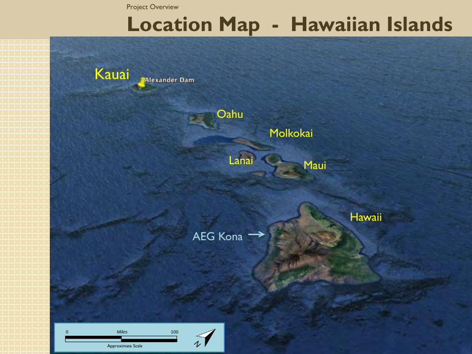
Location Map - Hawaiian Islands
Kauai
Hawaii
Maui
Molkokai
Lanai
Oahu
Approximate Scale
0 Miles 100
AEG Kona

Project Overview
Kauai Location Map(with Alexander Dam)
Eleele
Kalaheo
Approximate Scale
0 Miles 5
Weimea
Kapa’a

Project Overview
Kauai
Approximate Scale
0 Miles 30
Geologic Map Major Geologic Features

Sugarcane
Sugarcane in Hawaii The reason for the dam!
1875 Treaty allowed sale of sugarcane to US without taxes
Hawaii sugarcane production & sugar companies

• Needs water for more than six to seven months each year
• Rainfall not consistent enough, so irrigation needed
Sugarcane
Sugarcane needs continuous water supply

Project Overview
Existing Dam Layout
Approximate Scale
0 Feet 2000

Project Overview
Existing Dam Layout
Spillway
Dam Crest
Approximate Scale
0 Feet 500

Oblique Aerial ViewAlexander Dam

Oblique Aerial ViewAlexander Dam

Dam Design
Rolled Fill versus Hydraulic Fill
Main Factors for Hydraulic Fill• By the 1930’s rolled-fill embankment dams had poor
performance record in Hawaii due to “formation of water channels through compacted fill”;
• Site tests showed that void ratio = 3, after rolled compaction, so concluded that hydraulic fill better suited for site materials
Secondary Factors• Costly to transport construction equipment to this
remote site with steep terrain;• Belief at the time that with rolled embankments failure
could occur anytime during dam life, but that failure in hydraulic filled embankments could only occur during construction

Dam Design
Embankment Dimensions & ZonationOriginal Design
Sodium carbonate (Na2CO3) was added to the residual soil backfill compacted against the 8-ft deep concrete seepage cutoff wall, making this one of the first instances of chemically-treated soils.
HYDRAULIC FILLING
TECHNIQUE
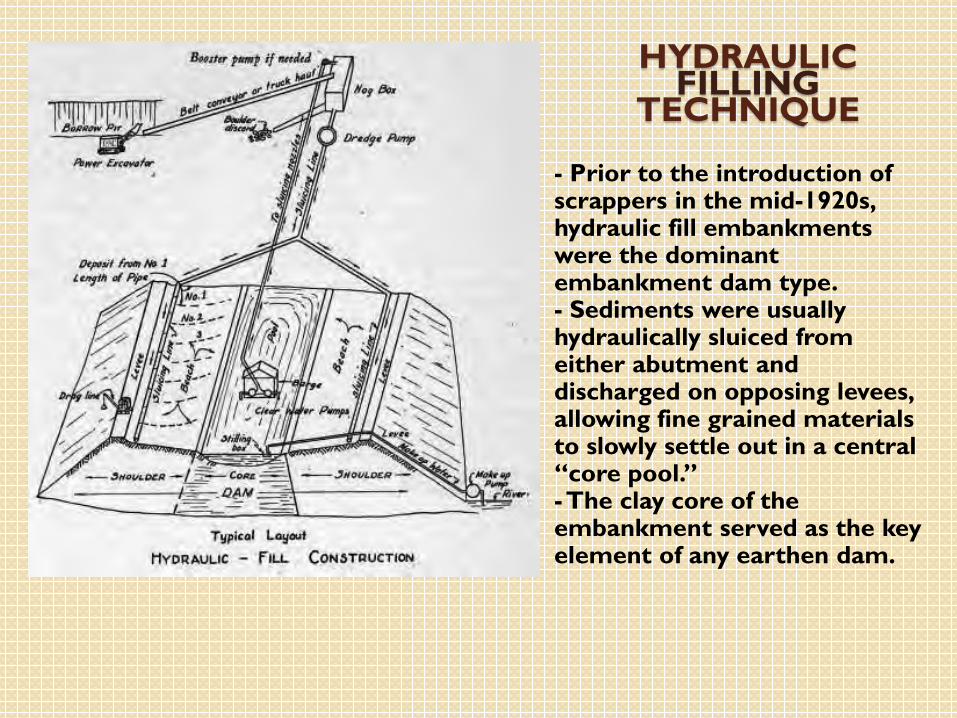
- Prior to the introduction of scrappers in the mid-1920s, hydraulic fill embankments were the dominant embankment dam type. - Sediments were usually hydraulically sluiced from either abutment and discharged on opposing levees, allowing fine grained materials to slowly settle out in a central “core pool.” -The clay core of the embankment served as the key element of any earthen dam.
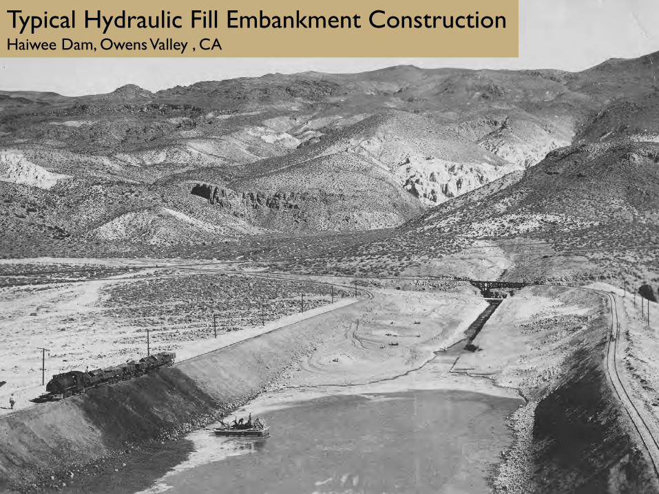
Typical Hydraulic Fill Embankment ConstructionHaiwee Dam, Owens Valley , CA

Common terminology for hydraulic fill dams

Materials used in the original embankment• “Fumarole ash” from the south abutment• “Decomposed vesicular lava” from the north abutment
• Hydraulic fill consisted of “heavy earth, claylike in character and variable in color, with red predominating…..the fine grains and colloidal material form the core”
Dam Design
Embankment Materials

Material presented two design problems. 1. Available materials created an abundance of fine-grained material and a dearth of
coarse-grained material for the shells underlying the slopes.
1. Saprolitic soils were disaggregated during excavation, hydraulic transport and surcharge, leading to a much lower hydraulic conductivity than the designers imagined possible beforehand.
More perviousLess pervious
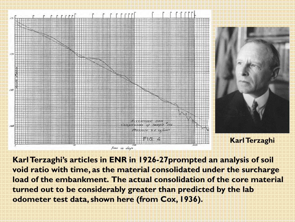
Karl Terzaghi’s articles in ENR in 1926-27prompted an analysis of soil void ratio with time, as the material consolidated under the surcharge load of the embankment. The actual consolidation of the core material turned out to be considerably greater than predicted by the lab odometer test data, shown here (from Cox, 1936).
Karl Terzaghi

“The response to the cessation of sluicing operations was prompt in the upper level, slower lower down. The lag due to a height of 100 feet was about 3 weeks. As the dam increased in height and [pore] pressures increased, the permeability of the material surrounding the drains decreased, so that less water was to be handled, the pressure head required remained nearly constant, only a moderate decrease in [pressure] head was observable.“ (J.B. Cox, ENR article of Oct 20, 1932)
Comment: These are the outward manifestations of internal drainage through the embankment shell was being compromised [lost].
DESIGN VERSUS AS-BUILT CONDITIONS

Record of movement observed along downstream face of embankment during failure of 1930

Failure Event
Embankment at the time of failure(Approx.)
Failure Event 3:45pm on March 23, 1930; suddenly and without warning(Plastic deformation (flow) of mud began some time before any mass movement was noticed)
At time of Failure Embankment height 95 ft; El. 1,575 ft 78% completeReservoir El. 1,535 (40 ft below constructed crest)
Failure 60-ft wide section of the core pool suddenly dropped ~30 feet and moved downstream, rapidly draining the pool and enlarging the mass.

Failure Event
Failed area of the Embankment
El. 1606’
1st section of dam built
Water level in reservoir=1535’
Embankment pool at time of failure=1575’
Core
• Failure occurred so quickly it killed six and injured two workmen on the downstream face.
• Volume of slide debris was ~257,000 yds3 (43% of placed embankment)

First is how deeply the materials on Kauai are weathered, • it being the oldest of the major [surviving] Hawaiian Islands, and
with the highest rainfall.
• Led to supplemental problems:• Available materials created an abundance of fine-grained
material and a dearth of coarse-grained material for the shells underlying the slopes.
• Saprolitic soils were disaggregated during excavation, hydraulic transport and surcharge, leading to a much lower hydraulic conductivity than the designers imagined possible beforehand.
Dam Failure
Dam failure centered on two issues
Materials composing the downstream shell did not drain internally
• Speculation that overburden loadings led to crushing which produced smaller particles.
• The increased pore water pressure lowered the strength of the shell material, supporting the much softer and heavier (saturated) core [an inherent problem of hydraulic fill dams]
• These particles plugged porosity and created a low permeability shell, inhibiting drainage of excess pore pressures.
• The build-up of pore water pressure within the downstream shell (beach) reduced the soil’s effective strength, hastening the slope failure that removed support of the core and core pool. Workers on the dam observed a cessation of drainage through the downstream shell in the vicinity of the failure about 10 days prior to the failure
Dam Failure
Dam failure centered on two issues
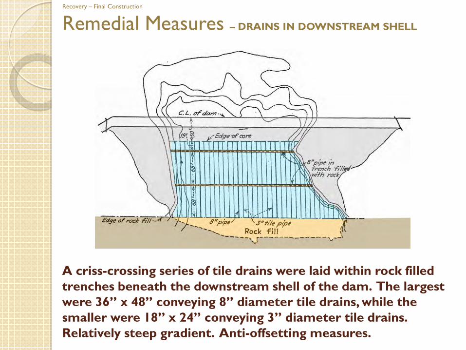
A criss-crossing series of tile drains were laid within rock filled trenches beneath the downstream shell of the dam. The largest were 36” x 48” conveying 8” diameter tile drains, while the smaller were 18” x 24” conveying 3” diameter tile drains. Relatively steep gradient. Anti-offsetting measures.
Recovery – Final Construction
Remedial Measures – DRAINS IN DOWNSTREAM SHELL
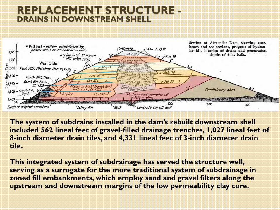
REPLACEMENT STRUCTURE -DRAINS IN DOWNSTREAM SHELL
The system of subdrains installed in the dam’s rebuilt downstream shell included 562 lineal feet of gravel-filled drainage trenches, 1,027 lineal feet of 8-inch diameter drain tiles, and 4,331 lineal feet of 3-inch diameter drain tile.
This integrated system of subdrainage has served the structure well, serving as a surrogate for the more traditional system of subdrainage in zoned fill embankments, which employ sand and gravel filters along the upstream and downstream margins of the low permeability clay core.

REPLACEMENT STRUCTURE -EMBANKMENT SHOWN AS COMPLETED
Embankment Mitigation – 3 Major Changes1. Downstream shell width increased as much as possible within
topographic and economic limits2. 40-ft high rock buttress placed across the downstream toe3. Most importantly, a drainage system installed in the downstream
beach section using tile drains in rock filled trenches.
• Retrofitted structure completed December 1932, remains in service

CORE POOL OF ALEXANDER DAM IN NOVEMBER 1931
-View along axis of the dam as the new core pool of the rebuilt structure was topped off in November 1931. Downstream is to left, reservoir to the right.
- Note that the core pool becomes smaller with increasing height, but also promotes increased hydraulic pressure head, commensurate with such height
CONCLUSIONInherent instability of hydraulic fill dams
• Not only a seismic concern because of low relative density of cohesionlessmaterials, but also vulnerable to pore pressure-induced problems during construction, if insufficient internal drainage. Glacial outwash deposits are particularly well-suited to hydraulic fill structures, but not poorly graded soil mixtures
Fill using volcanic residuum• Problematic because of disaggregation and breakdown of clods, creating
a semi-impervious and low strength fill• Points out the need for thorough testing of materials in both wet and dry
states, to gauge how material properties change with increasing effective stress and percent saturation
Implications for other hydraulic fill embankments• While hydraulic fill embankments are not widely used in the US today;
tailings dams are widely employed across the US and internationaly and this phenomenon should be considered at those facilities
• Points out the need for integrated internal drainage systems

Failure of the Alexander Dam Embankment on Kauai in 1930 J. David Rogers (Missouri University of Science and Technology); Kerry D. Cato (California State University San Bernardino)Alexander Dam is a hydraulic fill earth dam that was built in 1929-32 to provide irrigation for McBryde Sugar Co. Ltd. that operated on the south shore of Hawaiian island of Kauai. It was constructed across Wahiawa Stream mauka of Kalaheo to store 800 million gallons of water to irrigate sugar cane fields. The embankment dam was intended to have a maximum height of 125-ft, length of 620-ft, and a maximum base thickness of 640-ft. The total design volume was 580,000 yds3, using hydraulic fill sluiced to the dam site. On March 23, 1930, a 60-ft wide section of the core pool suddenly dropped ~30 feet and moved downstream, rapidly draining the pool and enlarging the mass. The embankment was at a height of 95-ft and 78% complete when the failure occurred. The failure occurred so quickly it killed six and injured two workmen on the downstream face. The volume of side debris was ~275,000 yds3. 30 vertical feet of the embankment’s clay core stood near-vertical after the failure, leading engineers to believe that the materials deposited in the downstream shell had consolidated and thereby failed to allow internal drainage. The embankment was rebuilt by emplacing a 40-ft high rock buttress across the downstream toe; the downstream shell was widened; and tile drains were inserted to facilitate internal drainage. The retrofitted structure was completed in December 1932 and remains in service. The materials used in the original and rebuilt embankment consisted of fumarole ash from the south abutment and decomposed vesicular lava from the north abutment. The hydraulic fill consisted of “heavy earth, claylike in character and variable in color with red predominating…..the fine grains and colloidal material form the core”. This material presented two design problems. First, the available materials created an abundance of fine-grained material and a dearth of coarse-grained material for the shells underlying the slopes. Second, the saprolitic soils were disaggregated during excavation, hydraulic transport and surcharge, leading to a much lower hydraulic conductivity than the designers imagined possible beforehand.
ABSTRACT