family brand series
TRANSCRIPT

MODEL ZENITH 9000 SERIESWITH PEDAL LOCK AND
ADVANCED POSITIONING (APS)FEATURES
SERIES
To avoid personal injury or damage to bed,read all sections pertaining to the bed model before use.
GF Health Products, Inc. - www.grahamfield.com Zenith Series Instructions for Use 999-0909-190A APR 2017
INSTRUCTIONS FOR USE
FDA Recognized Standard:ANSI/AAMI STD ES60601-1
Health Canada Recognized Standard:CAN/CSA C22.2 No. 60601-1 (IEC 60601-1:2012-Ed.3.1)
Includes International Standards:IEC 60601-1, IEC 60601-1-2, IEC 60601-2-52
EMC Standard:IEC 60601-1-2 Ed. 4.0
ZENITH™
SERIES
A Graham-Field® Family Brand

TABLE OF CONTENTSIMPORTANT SAFETY AND WARNING INFORMATION...................................................................................................... 3
IMPORTANT SAFETY AND WARNING INFORMATION ......................................................................................... 4ELECTROMAGNETIC COMPATIBILITY (EMC) INFORMATION............................................................................. 4ENTRAPMENT AND COMPLIANCE INFORMATION .............................................................................................. 5RECOMMENDED MAINTENANCE .......................................................................................................................... 6
MECHANICAL AND ELECTRICAL INFORMATION ............................................................................................................ 7OPERATING CONDITIONS ...................................................................................................................................... 8STORAGE AND TRANSPORT CONDITIONS ......................................................................................................... 8DISPOSAL OF EQUIPMENT AND ACCESSORIES ................................................................................................ 8
BED SETUP AND OPERATION INSTRUCTIONS ................................................................................................................ 9UNPACKING THE BED ............................................................................................................................................ 9HEADBOARD AND FOOTBOARD ASSEMBLY / INSTALLATION ....................................................................... 10SLIDE-W-I-D-E HEADBOARD AND FOOTBOARD POSITIONS USING THE QUICK-RELEASE DETENT PINS .11STANDARD MATTRESS RETAINER INSTALLATION .......................................................................................... 12MATTRESS RETAINER INSTALLATION FOR OPTIONAL SLIDE-W-I-D-E DECK .............................................. 13STANDARD WIREFORM WALLSAVER INSTALLATION ...................................................................................... 14OPERATING THE OPTIONAL CASTER PEDAL LOCK MECHANISM ................................................................. 15PLUGGING IN THE FOOTBOARD STAFF CONTROL .......................................................................................... 15
ZENITH SERIES OPTIONAL ACCESSORIES ............................................................................................................................16
OPERATION OF OPTIONAL SLIDE-W-I-D-E 35" - 39" - 42" EXPANDABLE / RETRACTABLE SLEEP DECK ............. 19IMPORTANT SAFETY AND WARNING INFORMATION ....................................................................................... 19FEATURES .............................................................................................................................................................. 19SLIDE-W-I-D-E SLEEP DECK POSITIONING ........................................................................................................ 20
BED OPERATION ............................................................................................................................................................... 21ZENITH SERIES HAND CONTROL PENDANT OPERATION ............................................................................... 21BED OPERATION - OPTIONAL STAFF CONTROL PANEL * ............................................................................... 22BED OPERATION - CHAIR POSITION .................................................................................................................. 23BED OPERATION - TRENDELENBURG / REVERSE TRENDELENBURG POSITION ....................................... 24
TROUBLESHOOTING ........................................................................................................................................................ 26
LIMITED WARRANTY ......................................................................................................................................................... 29
These Instructions for Use cover the Zenith Series with Standard and Advanced Positioning (APS), Standard Casters and Pedal-Lock option, for Standard Deck and Slide-W-I-D-E® Deck.
The Zenith Series is designed for Adult Patient and Caregiver use.
To order Zenith Series Bed service parts, contact a GF Health Products, Inc. customer service representative at 1-770-368-4700.
For a list of Zenith Series bed service parts, visit www.grahamfield.com.
To order a Zenith Series bed or accessories, contact a GF Health Products, Inc. sales representative at 1-770-368-4700.
Important Notice: Check all parts for shipping damage and test before using. In case of damage, DO NOT USE — contact qualified service personnel for examination and repair.
LABEL SYMBOL DEFINITIONS
!!ProtectedGrounded
Device
SafeWorking
Load
Consult Accompanying
Documents
Type BEquipment andApplied Parts
FollowInstructions
for Use
DoubleInsulated
GF Health Products, Inc. - www.grahamfield.com Zenith Series Instructions for Use 999-0909-190A
ZENITH SERIESA Graham-Field® Family Brand
2

IMPORTANT SAFETY AND WARNING INFORMATION
! This product is a variable height, adjustable mattress
platform. The expected service life of this product is fifteen years. Beds manufactured by Basic American Medical Products are designed for use within an institutional healthcare environment (i.e. assisted living, skilled nursing, transitional care, rehabilitation care, Environment (3), as defined in IEC60601-2-52 Safety Standard.).
! The maximum safe working load for the Zenith 7000
series bed, including bedding, resident / patient, support surface, and accessories, is 500 lb (226.8 kg), with weight evenly distributed, and maximum patient weight is 450 lb (204.1 kg).
The maximum safe working load for the Zenith 9000 series bed, including bedding, resident / patient, support surface, and accessories, is 600 lb (272.2 kg), with weight evenly distributed, and maximum patient weight is 550 lb (249.5 kg). Accessory weights follow:
! The bed’s Hand Control Pendant Cable MUST BE
ROUTED AND SECURED PROPERLY to ensure it does not become entangled and eventually severed during use. Also ensure electrical cords DO NOT get tangled around the bed, side rails, or legs during transport or normal operation of the bed.
! When using nasal-type or masked-type administering
equipment, all oxygen or air tubing MUST BE ROUTED AND SECURED PROPERLY to ensure the tubing does not become entangled and eventually severed during the normal operation of the bed.
! Keep all moving parts free of obstructions (i.e.
blankets / sheets, heating blankets / pads, wiring, etc.).
! DO NOT use the assist devices as push handles for
moving the bed. Assist devices can be deformed or broken if excessive side pressure is exerted. Assist devices are not meant for patients considered high risks for entrapment (i.e. patients with pre-existing conditions such as confusion, restlessness, lack of muscle control, altered mental status, either organic or medicinal, or a combination thereof). Additional safety measures should be considered for such high-risk patients.
! NEVER permit more than one person on / in the bed
at any time.
! Body weight should be evenly distributed over the
sleeping surface of the bed. DO NOT allow the patient to lie, sit, or lean in such a way that their entire body weight is placed only on the raised head or foot section of the bed. This especially applies when repositioning or transferring a patient in or out of the bed. Increased risk may occur when the patient’s size and / or weight are inappropriate for the bed’s dimensions or weight capacity.
! Risk of entanglement or injury may occur if the
mattress used with mattress retainers does not fill the entire width between stops or which compresses to less than 1.50 inches under user’s weight.
! Mattress must be properly sized to fit the mattress
support platform and must remain centered on the support platform relative to State and Federal guidelines. Recommended minimum dimensions of mattress are 35-36 inches wide and 6 inches deep. Length and width should match the mattress support platform. Use of an improperly fitted mattress could result in injury or death.
ACCESSORY DESCRIPTION WEIGHTExtension Kit, Standard Width 12 lb (5.4 kg) Extension Kit, Wide 14 lb (6.4 kg)Trapeze Adapter 13 lb (5.9 kg)Trapeze 16 lb (7.3 kg) Half Counter-Rotating Assist Device (Set of 2)
21 lb (9.5 kg)
Fixed Assist Bar, Head 6 lb (2.7 kg) Pivoting Assist Bar 10 lb (4.5 kg)
! WARNING: To avoid risk of electric shock, this
equipment must be connected to a supply mains with protective earth (i.e. a grounded outlet).
! DO NOT open assemblies such as the Actuators, Hand
Control Pendant, or Control Box. If unauthorized personnel perform work on these components, the manufacturer’s warranty becomes void.
! DO NOT use unauthorized parts, accessories, or
adapters other than those specified / authorized by GF Health Products, Inc.
! When operating the HI/LO, Knee, or Back Functions
of the bed, ALWAYS ensure the confined individual is positioned properly within the confines of the bed. DO NOT let any extremities protrude over the side or between the bed rails when performing these functions.
! The bed should be lowered to lowest position when
resident is left unattended. DO NOT lower the bed when objects are beneath it. Failure to inspect under the bed can result in personal injury or property damage.
GF Health Products, Inc. - www.grahamfield.com Zenith Series Instructions for Use 999-0909-190A
3
ZENITH SERIESA Graham-Field® Family Brand

IMPORTANT SAFETY AND WARNING INFORMATION
! IMPORTANT: Powered air mattress surfaces may
pose a risk of entrapment. Prior to use, ensure the therapeutic benefits outweigh the risk of entrapment.
! The bed is intended for use within a temperature
range of 10˚C to 40˚C. It has a water resistance rating of IPX4 and IS NOT to be power washed or submerged. The bed may be cleaned as needed using an appropriate dilution of mild soap and water.
! The head / back and knee / foot decks can be lifted
freely by hand for easy cleaning access when patients are not in the bed. If you lift the head / back or knee / foot deck for any reason, take great care when lowering back down to the prone position - ensure all body parts are clear of the space between the deck and the bed prior to slowly lowering any deck manually. To avoid injury, DO NOT LET DECKS FALL FREELY FROM ANY ANGLE.
! Notice for California Customers - California
Proposition 65 WARNING: This product contains a chemical known to the State of California to cause cancer and reproductive or developmental harm.
! WARNING: ALWAYS position bed so that the power
cord and plug are easily accessed.
! Proper routing and tie-off of electrical cabling,
especially the power cord, is essential for proper operation and to ensure safety from electrical shock. In the event you are replacing any electrical cabling on your bed, you must ensure the cables are free from pinch points, obstructions, or stretched so tight that they may come loose or become damaged. In addition, cables should be tied off in such a way to secure them and keep them free from tangling on any part of the bed during normal operation. Refer to page 23 for proper cable routing.
ELECTROMAGNETIC COMPATIBILITY (EMC) INFORMATION
! WARNING: Medical Electrical Equipment needs
special precautions regarding EMC and needs to be installed and put into service according to the EMC information provided in this manual.
! WARNING: Electronic equipment may be influenced
by Radio Frequency (RFI). Caution should be exercised with regard to the use of portable communications in the area around such equipment. Portable RF communications equipment (including peripherals such as antenna cables and external antennas) should be used no closer than 30 cm (12 inches) to any part of the bed including specified bed cables. Degradation of the performance of the bed could result.
! IF RFI causes erratic behavior, unplug the
electric bed immediately. Leave unplugged while transmission is in progress.
! WARNING: The use of accessories, tranducers,
and cables other than those specified by the manufacturer may result in increased emissions or decreased immunity of the bed. GF Health cables and accessories include motor cables, mains cable, pendant cables, back up battery and cable, USB port cable and UBL and cable.
! WARNING: This bed should not be used adjacent
to or stacked with other equipment. If adjacent or stacked use with other equipment is necessary, this bed and the other equipment should be observed to verify that they are operating normally.
! WARNING: The EMISSIONS characteristics of
this equipment make it suitable for use in industrial areas and hospitals (CISPR 11 class A). If it is used in a residential environment (for which CISPR 11 class B is usually required) this equipment might not offer adequate protection to radio frequency communication services. The user might need to take mitigation measures, such as relocating or re-orienting the equipment.
GF Health Products, Inc. - www.grahamfield.com Zenith Series Instructions for Use 999-0909-190A
ZENITH SERIESA Graham-Field® Family Brand
4

ENTRAPMENT AND COMPLIANCE INFORMATIONOn April 10, 2006, the FDA (U.S. Food and Drug Administration) released long-awaited guidelines for reducing the risk of bed entrapment: “Hospital Bed System Dimensional and Assessment Guidance to Reduce Entrapment”. The new Guidance identifies potential entrapment areas and those body parts most at risk for entrapment; provides design criteria for manufacturers of new hospital/convalescent beds; recommends particular test methods to assess the conformance of existing hospital / convalescent bed systems; and answers frequently-asked questions about entrapment issues.
The new Guidance was a result of a long-standing collaboration between the FDA and the Hospital Bed Safety Workgroup (HBSW), formed in 1999. GF Health Products, Inc.’s Long Term Care Bed division: Basic American Medical Products, is an HBSW charter member. As a result of our commitment to product safety, all our current long-term care beds have been strictly tested and conform to the new FDA Guidance.
The guidelines set forth by the FDA Guidance lay out specific dimensional limitations on potentially injury-threatening gaps and spaces that can occur between bed system components, such as rails, when not properly installed. GF Health Products, Inc. and Basic American Medical Products have conformed to these guidelines from a manufacturing aspect. However,
entrapment issues can often arise when a healthcare provider / facility has not correctly assembled the components on a bed. It is essential that the provider / facility fully understand their responsibility in complying to the guidelines set forth by the FDA in order to avoid injury. To that end, we have provided the FDA’s web address at right as a resource for understanding and following these guidelines for the safety of patients / residents.
It is also essential to have the correct bed components / accessories that correspond with the needs of the patient / resident and the particular bed you have purchased. Matching the correct bed component that correlates with the regulatory guidelines can be a daunting task. Our sales team at GF Health Products, Inc. and our friendly Customer Service Representatives at Basic American Medical Products can help you sift through the wide array of compliance and bed options. We will help you determine which bed / bed part is best for the patient’s / resident’s particular needs and help you with any compliance issues.
The Zenith series bed and accessories listed in these instructions are in full compliance with FDA guidelines for reducing the risk of bed entrapment: “Hospital Bed System Dimensional and Assessment Guidance to Reduce Entrapment”.
Details can be found at www.fda.gov.
GF Health Products, Inc. - www.grahamfield.com Zenith Series Instructions for Use 999-0909-190A
5
ZENITH SERIESA Graham-Field® Family Brand

RECOMMENDED MAINTENANCERegular maintenance of the Long Term Bed is necessary to ensure continuing proper and safe operation. Read and observe the following recommended maintenance schedule. Additional Maintenance Log pages are available at the end of these instructions.
RECOMMENDED INSPECTION PERIODS
MAINTENANCE
ITEM Inspect on Receipt
Every 3 Months
Every 6 Months
Performed by
Date Comments
Maintenance Inspection of All Components at Receipt of Shipment
Ensure all parts / components are included (see “Unpacking The Bed”).
X
Check all bed components for obvious damage. X
Inspect the power cord for any cuts and / or damage. X
Check to see all actuator / motor cables are routed and connected properly to the control box.
X
Mechanical Inspection of Assemblies
Inspect all welds on the sleeping surface, frame, and base assemblies for stress fractures.
X
Inspect all fasteners for wear and looseness. X
IMPORTANT: Lubricate all pivot points, actuator / motor clevis pins, and control arm clevis pins as needed. White Lithium Grease is recommended.
X
Mechanical Inspection of Casters and Pedal Locking Mechanism
Check the pedal locking mechanism to ensure it engages and disengages properly.
X
Check the casters and stationary foot pads on both the head end and foot end for any damage, wear, or debris. Replace if needed.
X
Check all rolling casters to ensure that they roll properly and are unobstructed.
X
Electrical Inspection of Control Box, Hand Control Pendant, and Staff Control
Check the external power cord that plugs into the control box for any chafing, cuts, or wear. Replace if damaged.
X
Ensure all attaching hardware is securely tightened. X
Check all electrical connections for wear or fractures. X
Check the external backup battery (if you have one). Replace if needed.
X
Check the hand control pendant cable for chafing, cuts, or wear.
X
Check all hand control pendant functions - check to ensure each button and associated function work properly (i.e. head section rises when the HEAD UP button is activated).
X
Electrical Inspection of Actuators / Motors
Check the actuator / motor cables for any chafing, cuts, or wear.
X
Check the range of movement on all motors to ensure they do not bind in the Full Up or Full Down positions.
X
GF Health Products, Inc. - www.grahamfield.com Zenith Series Instructions for Use 999-0909-190A
ZENITH SERIESA Graham-Field® Family Brand
6

MECHANICAL AND ELECTRICAL INFORMATIONZENITH SERIES-MECHANICAL NOTE: All dimensions are ±0.25 inches
Specification 7100 9100 7100 with SLIDE-W-I-D-E
9100 with SLIDE-W-I-D-E
Overall Bed Length (with boards and wallsaver)
76" 82" 82" 82" 82"
80" 86" 86" 86" 86"
Sleep Deck Width 35" 35" 35"-39"-42" 35"-39"-42"
Bed Width Including Boards 36" 36" 36" or 42" 36" or 42"
Maximum Height (floor to top of mattress support deck) 30" 30" 30" 30"
Minimum Height (floor to top of mattress support deck) 7.95" 7" 7.95" 7"
Maximum Head / Back Deck Angle 68° 68° 68° 68°
Maximum Knee / Foot Deck Angle 25° 25° 25° 25°
Maximum Trendelenburg / Reverse Trendelenburg Angle (APS models)
15° 14° 15° 14°
Maximum Safe Working Load WITH WEIGHT EVENLY DISTRIBUTED - includes bedding, resident / patient, support surface, and accessories
500 lb (226.8 kg)
600 lb (272.2 kg)
500 lb (226.8 kg)
600 lb (272.2 kg)
Bed Mass (standard deck, without assist devices or boards)
204 lb (92.5 kg)
218 lb (98.9 kg)
227 lb (102 kg)
241 lb (109.3 kg)
ZENITH SERIES-ELECTRICAL (ALL MODELS)Power / Frequency 120 Volt / 50/60 Hz
Output Rating 24Vdc
Maximum Amperage 4.5 Amps
Classification Class 1, Type B
Power (Electrical) Cord #18 AWG 3 Conductor Type SJT
Mode of Operations 10% Max. Duty Cycle (2 minutes on / 18 minutes off)
Battery Pack and Charger can be purchased separately as accessories.
TYPICAL ZENITH SERIES BED IDENTIFICATION LABELS with Grounded Electrical Cable
Bed labels are an important part of identifying the bed’s make and model when ordering replacement parts. The Serial Number is essential if you are claiming parts or service under warranty. These helpful labels can be located on the main frame rails, immediately below the sleep decks on either side of the bed.
Have this IMPORTANT information ready when calling our Customer Service or Technical Support staff at 1-770-368-4700; it will allow us to better assist you and quickly answer your questions and concerns.
! WARNING: Do not modify this equipment without
authorization from GF Health Products, Inc.NOTE: For Zenith Series Service Parts, Technical Assistance, and Information, call our Customer Service Department at 1-770-368-4700. For a list of Zenith Series bed service parts, visit www.grahamfield.com.
GF Health Products, Inc. - www.grahamfield.com Zenith Series Instructions for Use 999-0909-190A
7
ZENITH SERIESA Graham-Field® Family Brand
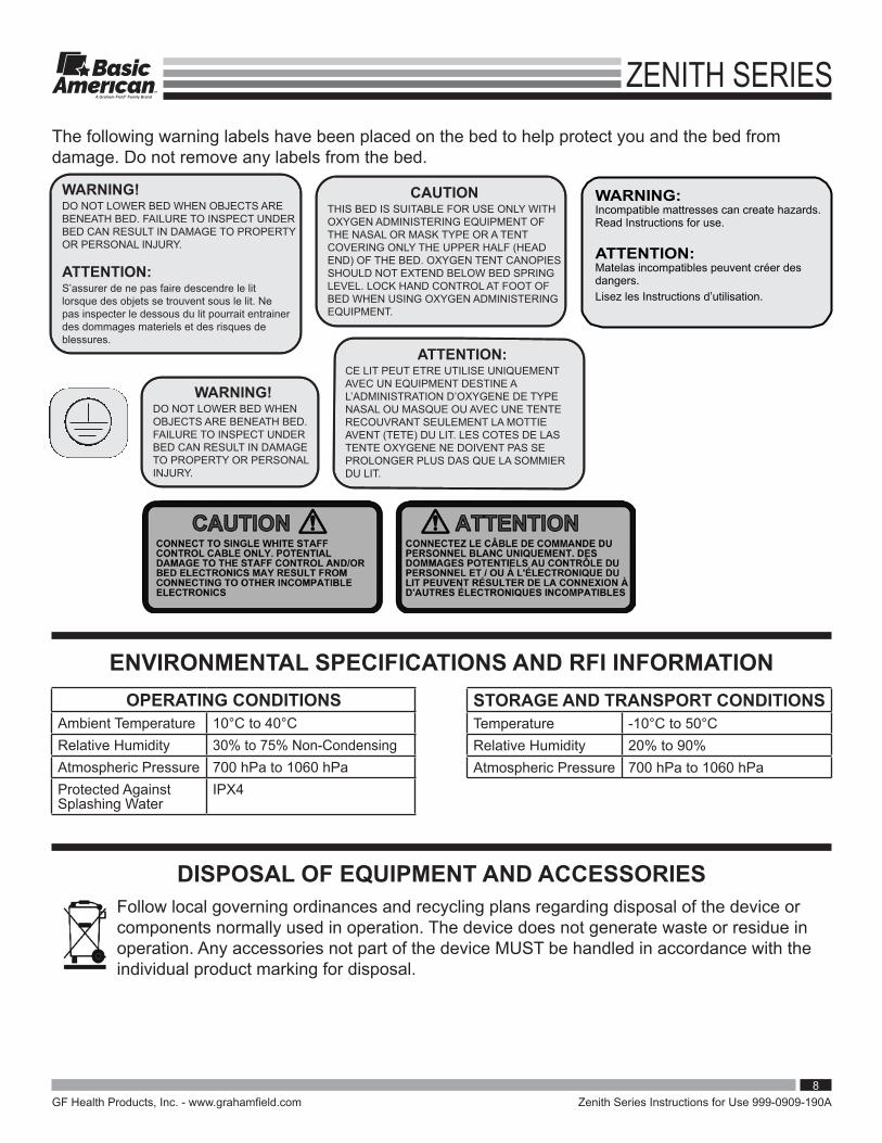
The following warning labels have been placed on the bed to help protect you and the bed from damage. Do not remove any labels from the bed.
WARNING!DO NOT LOWER BED WHEN OBJECTS AREBENEATH BED. FAILURE TO INSPECT UNDERBED CAN RESULT IN DAMAGE TO PROPERTYOR PERSONAL INJURY.
ATTENTION:S’assurer de ne pas faire descendre le lit lorsque des objets se trouvent sous le lit. Ne pas inspecter le dessous du lit pourrait entrainerdes dommages materiels et des risques deblessures.
WARNING!DO NOT LOWER BED WHENOBJECTS ARE BENEATH BED.FAILURE TO INSPECT UNDERBED CAN RESULT IN DAMAGETO PROPERTY OR PERSONALINJURY.
CAUTIONTHIS BED IS SUITABLE FOR USE ONLY WITHOXYGEN ADMINISTERING EQUIPMENT OFTHE NASAL OR MASK TYPE OR A TENT COVERING ONLY THE UPPER HALF (HEADEND) OF THE BED. OXYGEN TENT CANOPIESSHOULD NOT EXTEND BELOW BED SPRINGLEVEL. LOCK HAND CONTROL AT FOOT OFBED WHEN USING OXYGEN ADMINISTERINGEQUIPMENT.
ATTENTION:CE LIT PEUT ETRE UTILISE UNIQUEMENTAVEC UN EQUIPMENT DESTINE A L’ADMINISTRATION D’OXYGENE DE TYPENASAL OU MASQUE OU AVEC UNE TENTERECOUVRANT SEULEMENT LA MOTTIEAVENT (TETE) DU LIT. LES COTES DE LASTENTE OXYGENE NE DOIVENT PAS SE PROLONGER PLUS DAS QUE LA SOMMIERDU LIT.
WARNING:Incompatible mattresses can create hazards.Read Instructions for use.
ATTENTION:Matelas incompatibles peuvent créer desdangers.Lisez les Instructions d’utilisation.
ENVIRONMENTAL SPECIFICATIONS AND RFI INFORMATION
OPERATING CONDITIONSAmbient Temperature 10°C to 40°C
Relative Humidity 30% to 75% Non-Condensing
Atmospheric Pressure 700 hPa to 1060 hPa
Protected Against Splashing Water
IPX4
STORAGE AND TRANSPORT CONDITIONSTemperature -10°C to 50°C
Relative Humidity 20% to 90%
Atmospheric Pressure 700 hPa to 1060 hPa
DISPOSAL OF EQUIPMENT AND ACCESSORIESFollow local governing ordinances and recycling plans regarding disposal of the device or components normally used in operation. The device does not generate waste or residue in operation. Any accessories not part of the device MUST be handled in accordance with the individual product marking for disposal.
GF Health Products, Inc. - www.grahamfield.com Zenith Series Instructions for Use 999-0909-190A
ZENITH SERIESA Graham-Field® Family Brand
8

UNPACKING THE BED• Ensure all parts/components are included.• Check all bed components for obvious damage.• Inspect the Power Cord for cuts or damage.• Ensure all actuator/motor cables are routed
and connected properly to the control box.
BED SETUP AND OPERATION INSTRUCTIONS
DISCARD1. Large Block2. Notched 2 x 4 Board3. Honeycombed Block4. End Caps with Foam5. Notched Leg Foam6. Small Cable Tie - CUTKEEP7. Wireform Wallsaver (7A & 7B)8. Two Mattress Retainers9. Hand Control Pendant Holster
NOTE: END OF POWER CABLE IS COILED FOR SHIPPING AND TIED, WITH CABLE TIE, TO GRID WIRE WITH HAND CONTROL PENDANT, PENDANT CABLE AND HOLSTER.
CUT AND DISCARD CABLE TIE AROUND CABLES WHEN YOU UNPACK THE BED.
GF Health Products, Inc. - www.grahamfield.com Zenith Series Instructions for Use 999-0909-190A
9
ZENITH SERIESA Graham-Field® Family Brand

HEADBOARD AND FOOTBOARD ASSEMBLY / INSTALLATION1. HEADBOARD INSTALLATION• The headboard comes with four pre-installed
inserts - consider this the inside of the headboard.
• Position two mounting tubes on the outside of the headboard with “L” facing inward.
• Align the mounting tube top holes with the headboard top holes.
• Insert a 40mm long socket head cap screw through each of the top holes and bottom holes and screw into each insert. Tighten with the hex key included in the kit.
• At the head deck end, slide the mounting tube “L” portions into the main frame rail hollow ends.
• FOR 80" BEDS: Slide the mounting tubes in until the first tube hole aligns with the first rail hole. See illustration below.
• FOR 76" BEDS: Slide the mounting tubes in until the first tube hole aligns with the second rail hole. See illustration below.
2. FOOTBOARD INSTALLATION• The footboard comes with four pre-installed
inserts - consider this the outside of the footboard.
• Position two mounting tubes on the inside of the footboard with “L” facing inward.
• Align the mounting tube top holes with the footboard top holes.
• Insert a 40mm long socket head cap screw through each of the top holes and bottom holes and screw into each insert. Tighten with the hex key included in the kit.
• At the foot deck end, slide the mounting tube “L” portions into the main frame rails hollow ends.
• FOR 80" BEDS: Slide the mounting tubes in until the first tube hole aligns with the second rail hole. See illustration below.
• FOR 76" BEDS: Slide the mounting tubes in until the first tube hole aligns with the third rail hole. See illustration below.
HEADBOARD FOOTBOARDInsertson inside
40mmBolts
CENTEROF BED
CENTEROF BED
80" hole position(1st hole in)
80" hole position(2nd hole in)
76" hole position(2nd hole in)
76" hole position(3rd hole in)
Insertson outside
40mmBolts
NOTE: The 1st hole at the foot end is reserved forattaching the Optional 4" pan extension.
1st tube holeIMPORTANT:76" OR 80" HEADBOARD ANDFOOTBOARD POSITIONSMUST MATCH RETAINER ANDWALLSAVER POSITIONS. SEEPAGES 10 AND 11.
1st tube hole
GF Health Products, Inc. - www.grahamfield.com Zenith Series Instructions for Use 999-0909-190A
ZENITH SERIESA Graham-Field® Family Brand
10

SLIDE-W-I-D-E HEADBOARD AND FOOTBOARD POSITIONS USING THE QUICK-RELEASE DETENT PINS
HEADBOARD INSTALLATION
1. The headboard has four pre-installed inserts on the inside surface.
2. Position two mounting tubes on the outside of the headboard with “L” facing inward toward center of bed. Align the mounting tube top holes with the headboard top holes.
3. Insert socket head cap screws from Panel Mounting Kit through top holes into headboard.
4. Insert a second set of socket head cap screws through third-from-top tube holes into headboard. Hand tighten only.
5. From both sides, insert the lanyard-attached detent pins through the frame holes as shown, ensuring the detent pin balls extend completely through rails.
6. At the head end, slide the mounting tube “L” portions into the main frame rail hollow ends.
a. FOR 80" BED LENGTH: Slide the mounting tubes in until the first tube holes align with the first rail holes as shown below.
b. FOR 76" BED LENGTH: Slide the mounting tubes in until the first tube holes align with the second rail holes as shown below.
7. Tighten the four screws with the hex key included in the kit.
FOOTBOARD INSTALLATION
1. The footboard has four pre-installed inserts on the outside surface.
2. Position two mounting tubes on the inside of the footboard with “L” facing inward toward center of bed. Align the mounting tube top holes with the footboard top holes.
3. Insert socket head cap screws from Panel Mounting Kit through top holes into footboard.
4. Insert a second set of socket head cap screws through fourth-from-top tube holes into footboard. Hand tighten only.
5. From both sides, insert the lanyard-attached detent pins through the frame holes as shown, ensuring the detent pin balls extend completely through rails.
6. At the foot end, slide the mounting tube “L” portions into the main frame rail hollow ends.
a. FOR 80" BED LENGTH: Slide the mounting tubes in until the first tube holes align with the second rail holes as shown below.
b. FOR 76" BED LENGTH: Slide the mounting tubes in until the first tube holes align with the third rail holes as shown below.
7. Tighten the four screws with the hex key included in the kit.
HEADBOARD FOOTBOARD
Insertson inside
CENTEROF BED
CENTEROF BED
Insertson outside
40mmBolts
40mmBolts
IMPORTANT:76" OR 80" HEADBOARD AND FOOTBOARD POSITIONSMUST MATCH RETAINER AND WALLSAVER POSITIONS.SEE BED SERVICE MANUAL.
5/16 X 1.625" Detent Pin with Lanyard 100-7931-011Quantity = four (two per board)
first mountingtube hole for both76" and 80" positions
first mountingtube hole for both76" and 80" positions
80" hole position(first bottom hole
from end)
76" hole position(second bottom hole
from end)
Detent Pin (attachedto frame with Lanyard)
76" hole position(second bottom hole
from end)
80" hole position(first bottom hole
from end) Detent Pin (attached
to frame with Lanyard)
GF Health Products, Inc. - www.grahamfield.com Zenith Series Instructions for Use 999-0909-190A
11
ZENITH SERIESA Graham-Field® Family Brand

STANDARD MATTRESS RETAINER INSTALLATION (USING 2 MATTRESS RETAINERS)
1. Determine if you need to position your bed in an 80" or 76” configuration (80” outside holes; 76” inside holes - see Details A and B).
2. On the foot end, carefully squeeze the Mattress Retainer ends inward, toward the center of the retainer, and insert the ends into the proper holes (see Details A and B).
3. Lay the Mattress Retainer down so that the elbows rest on the decks and the long cross rod is on the foot end side as shown.
4. On the head end, carefully squeeze the Mattress Retainer ends inward, toward the center of the retainer, and insert the ends into the proper holes (see Details A and B).
5. Lay the Mattress Retainer down so that the elbows rest on the decks and the long cross rod is on the head end side as shown.
! Be sure to use a mattress that is properly sized to fit
the sleep deck, which will remain centered on the deck relative to State and Federal Guidelines. Use of an improperly fitted mattress could result in injury or death.
! Use a properly sized mattress in order to minimize
the gap between the side of the mattress and assist devices. This gap must be small enough to prevent resident/patient from getting their head or neck caught in this location.
DETAIL A:INSERT HEAD ENDMATTRESS RETAINER
DETAIL B:INSERT FOOT ENDMATTRESS RETAINER
Outside holes for 80" BedsInside holes for 76" Beds
IMPORTANT Ensure all three adjustable parts are properlypositioned for 76" or 80" configurations(See pages 9 and 11)
GF Health Products, Inc. - www.grahamfield.com Zenith Series Instructions for Use 999-0909-190A
ZENITH SERIESA Graham-Field® Family Brand
12

MATTRESS RETAINER INSTALLATION FOR OPTIONAL SLIDE-W-I-D-E DECK
1. The Slide-W-I-D-E Expandable/Retractable Sleep Deck features two sets of Mattress Retainers that are positioned at bed head and foot corners.
2. To install, position the mattress retainers above the sleep deck corners with ends perpendicular to the sleep deck surface and long crooked bent ends on outside as shown below.
3. Insert the rod ends into the appropriate 80" or 76" bed length holes as shown in detail at bottom right.
4. Once both ends are engaged, tilt each retainer toward the corner so that the retainer elbows rest on the deck.
IMPORTANTMATTRESS RETAINERS MUST MATCHHEADBOARD, FOOTBOARD, ANDWALLSAVER POSITIONS. SEE EACHBED MODEL’S SERVICE MANUAL.
To attach the four Mattress Retainers,insert Retainer ends into sleep deck
corner holes, then tilt Retainers downtoward corners
Outside cornerholes used for
80" bed positionHoles used for76” bed position
NOTE: CROOKEDEND IS ALWAYSON OUTSIDE
When in final position,all retainer elbows reston sleep deck surface
Left Foot CornerMattress Retainer
999-0881-001
HEAD END
FOOT END
Right Foot CornerMattress Retainer
999-0881-002
Left Head CornerMattress Retainer
999-0881-002
Right Head CornerMattress Retainer
999-0881-001
GF Health Products, Inc. - www.grahamfield.com Zenith Series Instructions for Use 999-0909-190A
13
ZENITH SERIESA Graham-Field® Family Brand

STANDARD WIREFORM WALLSAVER INSTALLATIONWALLSAVER ASSEMBLY
1. Position the Wireform Wallsaver with bent end facing upward and tab ends facing inward as shown above.
2. Determine the position desired (see WALLSAVER POSITIONS below).
3. Gently squeeze the wallsaver tab ends inward toward the center of the wallsaver and, holding the tabs parallel with the caster base slots, slide the tabs into the slots while letting the wallsaver gently expand outward.
4. Turn the wallsaver downward until it rests on the floor.
WALLSAVER REMOVAL
1. To remove or move the wallsaver to a new position, raise the wallsaver off the floor until the end tabs are horizontal.
2. Squeeze the ends toward the center of the wallsaver until the end tabs slide out of the caster base slots.
WALLSAVER POSITIONS
1. The Zenith wallsaver features two standard positions for easy bed/mattress length reconfigurations - 76" and 80".
2. For 76" beds, position the wallsaver ends in the BACK caster base slots (toward the foot end). For 76” beds using an optional Trapeze unit, position the wallsaver ends in the FRONT caster base slots (toward the head end.)
3. For 80” beds, position the wallsaver ends in the FRONT caster base slots (toward the head end).
GF Health Products, Inc. - www.grahamfield.com Zenith Series Instructions for Use 999-0909-190A
ZENITH SERIESA Graham-Field® Family Brand
14

PLUGGING IN THE FOOTBOARD STAFF CONTROL
STEP 1 - ATTACHING THE FOOTBOARDThe Zenith series bed features a footboard Staff Control; however, the footboard is ordered separately with your bed because of the variety of board styles available. If ordered at the same time as the bed, the Staff Control Assembly and Shroud Cover will be pre-installed to the Footboard at the factory.
ImproperConnection
(not completely seated)
DETAIL A:Ensure lock end
caps are screwedon securely
ProperConnection(completely seated)
STEP 2 - CONNECTING THE CABLES: REFER TO DETAIL A ABOVE
! WARNING: CONNECT TO SINGLE WHITE STAFF CONTROL CABLE ONLY. POTENTIAL INJURY OR DAMAGE TO THE STAFF CONTROL AND / OR BED ELECTRONICS MAY RESULT FROM CONNECTING TO OTHER INCOMPATIBLE ELCTRONICS.
a) Insert the T-Cable end (extending out the foot end with phone jack) into the round plug, making sure the phone jack is seated correctly inside the female plug (arrow to arrow – see DETAIL A and photos above).
b) Screw on the round lock cap onto the Staff Control female plug to secure (See DETAIL A).
FOOT END
FOOT END of Zenith Series BedShown with Pedal Lock Engaged
(RED DOWN = LOCKED POSITION)
GREEN DOWN = ROLL
RED DOWN = LOCKED
OPERATING THE OPTIONAL CASTER PEDAL LOCK MECHANISM
LOCKED POSITIONTo lock the foot end casters, step on the red pedal until the caster lock engages.
UNLOCKED POSITIONTo unlock the foot end casters, step on the green release pedal until the caster lock disengages.
GF Health Products, Inc. - www.grahamfield.com Zenith Series Instructions for Use 999-0909-190A
15
ZENITH SERIESA Graham-Field® Family Brand

ZENITH SERIES OPTIONAL ACCESSORIES
ZENITH 7100 / 9100 SERIES OPTIONAL ACCESSORIES
Pivot Assist Bar Fixed Assist Bar
Optional Counter-rotating Assist Device and Assist Bars provide a sturdy and securehand hold to assist residents in and out of bed.Assist devices are removable without tools and meetFDA Entrapment Guidelines.
• Move out of the way for lateral transfers.• Pivot away from egress area.• Provide toe clearance even in lowest
position to prevent staff injury.• Hand pendant mounts facing inward or outward
and away from hand grab area.
Pivot Assist Bar ZA90300 (tool-less) ZA87900 (bolt-on)
Fixed Assist Bar ZA85000 (tool-less)ZA87800 (bolt-on)
Pendant Hand Control and Holster Easy operation contoured pendant is shock-resistant, splash-proof anddurable. Holster conveniently secures to bedrails and assist devices foreasy access.
Can be attached with bolts or quick release pins.
Wide Deck Kit (for non-Slide-W-I-D-E beds)Optional wide kit adjusts the bed sleep deck to 39"or 42'' width for greater resident comfort. (Head andfoot boards and staff control electronics not included.)ZA858000 39" wide deck kitZA851000 42" wide deck kit
AccessoriesZA84200
For APS9000and APS7000
For Zenith9000,7000, and 5000
Embedded Staff Control• Angled for better visibility.• Two-stage lockouts to prevent pendant use, or to
prevent use of individual or multiple bed functions.• APS staff control also includes SafeMode, which
automatically locks out the high/low feature, if desired.ZL831000 (for use with APS bed models)ZL788000 (for Zenith9000, Zenith7000, and Zenith5000)
ZL831000 ZL788000
ZA90300 ZA85000
Counter-Rotating Assist (set of 2) Board-Mounted Hand Control Pendant Holster
Optional Counter-rotating Assist Device and Assist Bars provide a sturdy and securehand hold to assist residents in and out of bed.Assist devices are removable without tools and meetFDA Entrapment Guidelines.
• Move out of the way for lateral transfers.• Pivot away from egress area.• Provide toe clearance even in lowest
position to prevent staff injury.• Hand pendant mounts facing inward or outward
and away from hand grab area.
Pivot Assist Bar ZA90300 (tool-less) ZA87900 (bolt-on)
Fixed Assist Bar ZA85000 (tool-less)ZA87800 (bolt-on)
Pendant Hand Control and Holster Easy operation contoured pendant is shock-resistant, splash-proof anddurable. Holster conveniently secures to bedrails and assist devices foreasy access.
Can be attached with bolts or quick release pins.
Wide Deck Kit (for non-Slide-W-I-D-E beds)Optional wide kit adjusts the bed sleep deck to 39"or 42'' width for greater resident comfort. (Head andfoot boards and staff control electronics not included.)ZA858000 39" wide deck kitZA851000 42" wide deck kit
AccessoriesZA84200
For APS9000and APS7000
For Zenith9000,7000, and 5000
Embedded Staff Control• Angled for better visibility.• Two-stage lockouts to prevent pendant use, or to
prevent use of individual or multiple bed functions.• APS staff control also includes SafeMode, which
automatically locks out the high/low feature, if desired.ZL831000 (for use with APS bed models)ZL788000 (for Zenith9000, Zenith7000, and Zenith5000)
ZL831000 ZL788000
ZA84200 ZA9150
Bed Length Extension Kit (extends 35", 42", and Slide-W-I-D-E Deck)
4-inch Length Extension Kit :ZA90500
8-inch Length Extension Kit: ZA90400
GF Health Products, Inc. - www.grahamfield.com Zenith Series Instructions for Use 999-0909-190A
ZENITH SERIESA Graham-Field® Family Brand
16

Trapeze Adapter Kit Trapeze
ZA79000 ZA78100
Long (Trendelenburg) WallSaver Side-WallSaver Bumper (set of 2)
ZA90070 ZA86200 (35")
ZA89200 (42")
Plastic Pan Deck Kit Backup Battery & Battery Charger
ZA87500 Backup Battery: 999-0831-003
Battery Charger: 999-0711-002
GF Health Products, Inc. - www.grahamfield.com Zenith Series Instructions for Use 999-0909-190A
17
ZENITH SERIESA Graham-Field® Family Brand

USB Phone Charger-Power Supply Kit Under-Bed-Light Kit (must be used with Staff Control and/or APS Hand Control Pendant)
ZA90020 ZA90010
Advanced Positioning Backlit Hand Control Pendant with Trendelenburg / Reverse Trendelenburg
Advanced Positioning Backlit Hand Control Pendant with Chair Position only
ZA83106 999-0806-301SP
1-Person Bed Transport Dolly (set) Board-Mounted IV Socket Kit
ZA89900 unassembled ZA89900 assembled with bed
ZA19000
GF Health Products, Inc. - www.grahamfield.com Zenith Series Instructions for Use 999-0909-190A
ZENITH SERIESA Graham-Field® Family Brand
18

OPERATION OF OPTIONAL SLIDE-W-I-D-E 35" - 39" - 42" EXPANDABLE / RETRACTABLE SLEEP DECK
IMPORTANT SAFETY AND WARNING INFORMATION
! WARNING: Read and follow all instructions. Care must be taken when adjusting your Slide-W-I-D-E Expandable/
Retractable Sleep Deck. To avoid possible injury, keep hands clear of deck ends when expanding or retracting, especially near the headboard or footboard. To avoid pinching, the deck should only be adjusted from the side. Assist devices and mattress should be removed prior to adjusting the deck.
! WARNING: When expanding or retracting the deck, make sure to first remove the quick-release detent pins located on the
underside of both sides of the foot deck and head deck. Make sure to re-insert the pins into the proper width holes before allowing patient into the bed to avoid injury to the patient and damage to the decks. Pins must be fully seated before any operation of the bed.
! WARNING: Caregivers should be aware that the corners of the deck system may extend slightly past the headboard and
footboard at the corners. Care should be taken to avoid these areas when moving around the bed.
! WARNING: Patient body weight should be evenly distributed over the sleeping surface of the bed. DO NOT allow the patient
to lie, sit, or lean in such a way that their entire body weight is placed only on the raised head or foot section, or only one side of the bed. This especially applies when repositioning or transferring a patient in or out of the bed. Increased risk may occur when the patient’s size and/or weight are inappropriate for the bed’s dimensions or weight capacity. See your service manual for proper Maximum Safe Working Load for your model bed.
FEATURES
35"Fully Retracted
39"Partly Expanded
42"Fully Expanded
• Expandable/Retractable deck quickly and easily adjusts to 35”, 39”, and 42” with two quick-release ball-detent pins on each side.
• Quick adjustment is ideal for moving through narrow doorways.• All pins are attached to the bed with lanyards, eliminating lost parts.• Wide headboards and footboards are available in both 39” and 42” widths (both sold separately).• Rails and assist devices feature quick-release systems - no tools are required for assembly of
these devices (refer to your bed model’s Service Manual for more details).
GF Health Products, Inc. - www.grahamfield.com Zenith Series Instructions for Use 999-0909-190A
19
ZENITH SERIESA Graham-Field® Family Brand
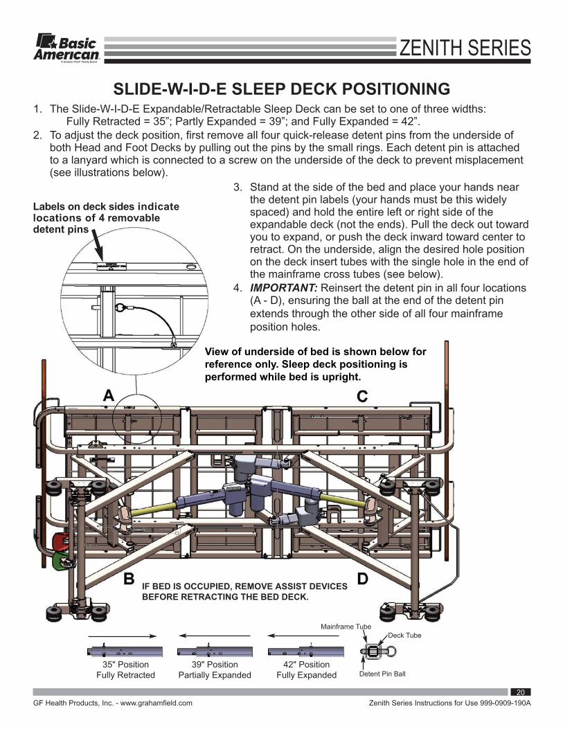
IF BED IS OCCUPIED, REMOVE ASSIST DEVICESBEFORE RETRACTING THE BED DECK.
35" PositionFully Retracted
39" PositionPartially Expanded
42" PositionFully Expanded Detent Pin Ball
Mainframe TubeDeck Tube
Labels on deck sides indicatelocations of 4 removabledetent pins
View of underside of bed is shown below forreference only. Sleep deck positioning isperformed while bed is upright.
SLIDE-W-I-D-E SLEEP DECK POSITIONING1. The Slide-W-I-D-E Expandable/Retractable Sleep Deck can be set to one of three widths:
Fully Retracted = 35”; Partly Expanded = 39”; and Fully Expanded = 42”.2. To adjust the deck position, first remove all four quick-release detent pins from the underside of
both Head and Foot Decks by pulling out the pins by the small rings. Each detent pin is attached to a lanyard which is connected to a screw on the underside of the deck to prevent misplacement (see illustrations below).
3. Stand at the side of the bed and place your hands near the detent pin labels (your hands must be this widely spaced) and hold the entire left or right side of the expandable deck (not the ends). Pull the deck out toward you to expand, or push the deck inward toward center to retract. On the underside, align the desired hole position on the deck insert tubes with the single hole in the end of the mainframe cross tubes (see below).
4. IMPORTANT: Reinsert the detent pin in all four locations (A - D), ensuring the ball at the end of the detent pin extends through the other side of all four mainframe position holes.
GF Health Products, Inc. - www.grahamfield.com Zenith Series Instructions for Use 999-0909-190A
ZENITH SERIESA Graham-Field® Family Brand
20

BED OPERATION
ZENITH SERIES HAND CONTROL PENDANT OPERATION
HAND CONTROL PENDANTOPERATIONBUTTON FUNCTION
1 HEAD DECK ANGLE UP2 HEAD DECK ANGLE DOWN3 HI/LO UP (RAISE ENTIRE BED)4 HI/LO DOWN (LOWER ENTIRE BED)5 KNEE AND FOOT DECK ANGLE UP6 KNEE AND FOOT DECK ANGLE DOWN7 SET TO CHAIR POSITION8 UNDO CHAIR POSITION9 REVERSE TRENDELENBURG POSITION
10 TRENDELENBURG POSITION 11 OPTIONAL UNDERBED LIGHT
ZENITH SERIES WITHADVANCED POSITIONING
HAND CONTROL PENDANT
OPTIONAL ACCESSORY:ZENITH SERIES WITHTRENDELENBURG /
REVERSE TRENDELENBURGHAND CONTROL PENDANT
ZENITH SERIES WITHSTANDARD POSITIONING
HAND CONTROL PENDANT
2
6
4
1
5
3
2
6
8
1
5
7
43
2
6
8
1
5
7
4
10
3
911
11
NOTE:
The Zenith Series Hand Control Pendant can be plugged into the T-cable plugs on either side of the bed for easy access. The opposite side of the T-Cable should always have the provided cap attached for safety.
The two vertical ends of the double T-Cable run toward the foot end of the bed, with one vertical end plugging directly into the control box (or optional Underbed Light if your bed has that feature) and the other longer end runs along the tie rod and extends out the foot end and plugs into the Staff Control cable.
GF Health Products, Inc. - www.grahamfield.com Zenith Series Instructions for Use 999-0909-190A
21
ZENITH SERIESA Graham-Field® Family Brand

BED OPERATION - OPTIONAL STAFF CONTROL PANEL *
* Staff Control with Advanced Positioning functions is shown above. Staff Control with Standard Positioning functions is shown at left; all standard functions operate the same as those defined above.
GF Health Products, Inc. - www.grahamfield.com Zenith Series Instructions for Use 999-0909-190A
ZENITH SERIESA Graham-Field® Family Brand
22

BED OPERATION - CHAIR POSITION
1. Ensure the Chair position on the StaffControl panel is not locked out (orange lockicon). To unlock, press Lock icon button #1and Chair icon button #2 (or “All Locked”button #3) simultaneously.
2. To move the bed to Chair position (foot andknee decks angled up, head deck angledup, and head of bed tilted up), press Chairicon button #2.
To release the chair feature and return the bedto horizontal position, press Flat Bar icon #4.
The Chair feature can also be operated using the Hand Control Pendant.
Chair positionUP and DOWN buttons
3 2
4
1
ZENITH SERIES WITHADVANCED POSITIONING
HAND CONTROL PENDANT
HEAD END
FOOT END
OPTIONAL ACCESSORY:ZENITH SERIES WITH TRENDELENBURG /
REVERSE TRENDELENBURGHAND CONTROL PENDANT
GF Health Products, Inc. - www.grahamfield.com Zenith Series Instructions for Use 999-0909-190A
23
ZENITH SERIESA Graham-Field® Family Brand

BED OPERATION - TRENDELENBURG / REVERSE TRENDELENBURG POSITION
1. Ensure the Staff Control HI/LO function is not locked out (orange lock icon). To unlock, simultaneously press Key 1 and HI/LO Locked button 2.
2. To move the bed to Trendelenburg position (foot end up), press button 3.
3. To move the bed to Reverse Trendelenburg position (head end up), press button 4.
GF Health Products, Inc. - www.grahamfield.com Zenith Series Instructions for Use 999-0909-190A
ZENITH SERIESA Graham-Field® Family Brand
24

ZENITH SERIES ELECTRICAL CABLING
GF Health Products, Inc. - www.grahamfield.com Zenith Series Instructions for Use 999-0909-190A
25
ZENITH SERIESA Graham-Field® Family Brand

TROUBLESHOOTINGNOTHING WORKS — NO POWER
! ALWAYS UNPLUG THE POWER CORD BEFORE PERFORMING MAINTENANCE ON THE BED.
1. Verify there is power in the wall outlet. Unplug the power cord from the outlet and test the outlet by plugging in a lamp or similar portable device. OUTLET WORKS: Move to Step 2.
2. Plug the power cord into the outlet – NOTHING WORKS: UNPLUG THE POWER CORD and check the power cord from the head end to the control box, ensuring it is not pinched, frayed, or damaged in any way.
a) POWER CORD IS PINCHED: With power cord unplugged, move the bed part slightly to release the pinched cord. If you can release the cord, replug the power cord into the outlet and test the bed.
b) BED WORKS: Ensure the cord is not frayed or exposed. If it is OK, you should not have to replace.
c) POWER CORD IS DAMAGED: Cut cable ties and immediately replace power cord.
! IF 3-PRONG POWER CORD IS DAMAGED, REPLACE IT IMMEDIATELY!
TROUBLESHOOTING PENDANT AND DOUBLE T-CABLE: STAFF CONTROL WORKS, BUT HAND CONTROL PENDANT FUNCTION DOESN’T
1. Check panel to see if Staff Control functions are locked out; if orange lock icon illuminates then that function is locked out. Press Key and Function (e.g. Head) buttons simultaneously until orange lock icon de-illuminates. Test function. If PENDANT STILL DOESN’T WORK: Go to step 2.
2. Check the connections at seat pan (Hand Control Pendant to T-cable) and Staff Control cable connection to T-cable at the foot end, ensuring plugs are fully engaged. Also check T-cable connection at Control Box. If you have the optional Underbed Light feature, ensure all cables are secure. If PENDANT STILL DOESN’T WORK: Go to step 3.
3. UNPLUG POWER CORD FROM WALL OUTLET.4. Unplug Hand Control Pendant plug from T-cable end on
either side of Seat Pan. Unplug Staff Control cable from foot end of T-cable and unplug other end from Control Box.
5. Plug Hand Control Pendant directly into Control Box HB port, ensuring it is fully seated. Plug in power cord and test Hand Control Pendant.a) ALL BUTTONS WORK: Replace T-cable.b) NOTHING WORKS: Continue Troubleshooting on
next page.
Note: Staff Control with Advanced Positioning functions is shown in A above. Operation of Staff Control with Standard Positioning functions is identical.
GF Health Products, Inc. - www.grahamfield.com Zenith Series Instructions for Use 999-0909-190A
ZENITH SERIESA Graham-Field® Family Brand
26

TROUBLESHOOTING STAFF CONTROL: STAFF CONTROL LIGHTS BLINK; NOTHING ON STAFF CONTROL WORKS, BUT HAND CONTROL PENDANT WORKS
! ALWAYS UNPLUG THE POWER CORD BEFORE PERFORMING MAINTENANCE ON THE BED.
1. This could mean the Staff Control is not getting enough power from the Control Box.
2. Unplug the power cord from the wall outlet. Unplug the Staff Control Cable from the T-Cable at the foot end of the bed.
3. If you have a spare Staff Control Assembly, plug the cable into the foot end T-cable and test.
a) STAFF CONTROL WORKS AND LIGHTS NO LONGER BLINK: Replace the Staff Control Assembly.
b) STAFF CONTROL DOESN’T WORK AND LIGHTS STILL BLINK: Continue Troubleshooting below.
Note: Staff Control with Advanced Positioning functions is shown above. Operation of Staff Control with Standard Positioning functions is identical.
TROUBLESHOOTING STAFF CONTROL: NOTHING ON STAFF CONTROL WORKS, BUT HAND CONTROL PENDANT WORKS
1. Check the Staff Control connections at the foot end. Is the Staff Control cable plugged securely into the T-cable? Also check if the other end of the T-cable is plugged securely into the Control Box (or Underbed Light). If the STAFF CONTROL STILL DOESN’T WORK: go to step 2.
2. Unplug the power cord from the wall outlet. Remove the Cable Cover (Shroud) on the inside of the footboard and locate the single terminal end that plugs directly into the back of the Staff Control Panel. Ensure it is properly seated in the panel. Plug in the power cord and test the Staff Control. If the STAFF CONTROL STILL DOESN’T WORK: Replace the Staff Control Assembly.
GF Health Products, Inc. - www.grahamfield.com Zenith Series Instructions for Use 999-0909-190A
27
ZENITH SERIESA Graham-Field® Family Brand

Power CordConnector
CONTROLBOX
Optional BatteryCable Connector
TROUBLESHOOTING MOTOR CABLES AND CONTROL BOX: A: HEAD, FOOT, OR HI/LO FUNCTION NOT WORKING
1. Check plugs to ensure they are plugged into the correct ports and firmly seated (see picture at right).
2. Check all cables to ensure they are not frayed, pinched, or damaged in any way. If any cable is damaged, UNPLUG THE POWER CORD FROM THE WALL OUTLET AND REPLACE THE CABLE AND / OR THE ELECTRONIC COMPONENT.
3. HEAD DECK NOT RISING: Unplug power cord. Switch head and foot plugs (Ports 1 and 3). Replug power cord.a) HEAD WORKS: Control Box head port is bad. Replace Control
Box and press the FOOT button to test.b) HEAD DOESN’T WORK: Replace Head Motor.
NOTE: FOOT DOWN will not operate if bed frame is not level. Verify HI/LO is not in CHAIR or REVERSE TRENDELENBURG position.4. FOOT AND KNEE DECKS NOT RISING: Unplug power cord. Switch
head and foot plugs (Ports 1 and 3). Replug power cord.a) FOOT WORKS: Control Box foot port is bad. Replace Control Box and press HEAD button to
test.b) FOOT DOESN’T WORK: Replace Foot Motor.
5. This bed has 2 motors for the HI/LO function. If one of the HI/LO motors is not moving bed up or bed down:a) Before removing any motor cables, try to re-synchronize the HI/LO function by following the steps
in section “B” below. After re-synchronizing, continue with next step if the problem continues.b) If bed still does not move up / down remaining horizontal: Possibility of a bad HI/LO motor or Control box. Unplug power cord from wall. At the control box,
switch the HI/LO motor cable for the potentially bad motor with the cable for the head motor (in port #1 of the Control box). Re-plug bed power cord into wall. Push Head up / down buttons on hand control. If HI/LO motor still does not run, replace that HI/LO motor. If HI/LO motor does run when pushing the head up / down buttons, try plugging the second HI/LO motor cable into the Head motor port on the Control box. If that HI/LO motor does not run, replace that HI/LO motor. If both first and second HI/LO motors work when plugged into the Head motor port, replace the Control box.
B. IF NEITHER HI/LO MOTOR OR ONLY ONE HI/LO MOTOR WORKS
On the Hand Control Pendant, simultaneously press and hold both HI/LO Up and HI/LO Down buttons (Control Box should start beeping) for approximately five seconds until beeping stops. Release the buttons, then press the HI/LO Down button and hold until bed is lowered completely into the lowest height position. When both HI/LO motors reach their lowest position, HI/LO motors will automatically resynchronize.
QUICK REFERENCE
• HI/LO AND FOOT WORKS, BUT HEAD DOES NOT: Switch Head and Foot Motor Cable at the Control Box and test (see step 3 above).
• HI/LO & HEAD WORKS, BUT FOOT DOES NOT: Switch Foot and Head Motor Cable at the Control Box and test (see Step 4 above).
• HEAD & FOOT WORKS, BUT HI/LO DOES NOT:
• Switch Head and Foot HI/LO Motor Cables at the Control Box and test (see Step 5 above).
• Test to see if HI/LO Motors need to be resynchronized.
GF Health Products, Inc. - www.grahamfield.com Zenith Series Instructions for Use 999-0909-190A
ZENITH SERIESA Graham-Field® Family Brand
28

LIMITED WARRANTYSCOPE OF WARRANTY
GF Health Products, Inc. (“GF”) warrants to the original purchaser only that it will replace or repair components, at GF’s sole discretion, that are defective in material or workmanship under normal use and service. All warranties are conditioned upon the proper use of the products strictly in accordance with good commercial practice and applicable GF instructions and manuals, including proper use and maintenance. To the extent that a component is warranted by a third party, GF conveys all of its rights under that warranty to the original purchaser, to the extent permitted.
This limited warranty shall only apply to defects that are reported to GF’s customer service team within the applicable warranty period and which, upon examination by GF or its authorized representative, prove to be a warranty item. This limited warranty is not transferable.
The warranted components and time period are set forth below:
Main Frame and welds: fifteen years Control Box and Actuator Motors: five years Hand Control Pendant, Staff Control, and Cabling three years Headboard and Footboard one year All other durable components not listed above: two years
Subsequent service parts under warranty until the original warranty set forth above expires, or for one year, whichever is greater.
The applicable warranty period shall commence from date of shipment to the original customer, unless there is an expiration date on the component in which case the warranty shall expire on the earlier of warranty period or the expiration date.
OBTAINING WARRANTY SERVICE
A GF Customer Service Representative must authorize warranty service. Please contact the GF Customer Service department by calling 1-770-368-4700, sending a fax request to 1-770-368-2386 or by e-mailing a request to [email protected]. Specific directions will be provided by the Customer Service Representative. Failure to abide by the specific directions will result in denial of the warranty claim.
EXCLUSIONS
The warranty does not cover and GF shall not be liable for the following:
1) Defects, damage, or other conditions caused, in whole or in part, by misuse, abuse, negligence, alteration, accident, freight damage, tampering or failure to seek and obtain repair or replacement in a timely manner;
2) Products which are not installed, used, or properly cleaned and maintained as required in the official manual for the applicable product;
3) Products considered to be of a non-durable nature including, but not limited to: casters, filters, fuses, gaskets, lubricants, and charts;
4) Accessories or parts not provided by GF;
5) Charges by anyone for adjustments, repairs, replacement parts, installation or other work performed upon or in connection with such products which are not expressly authorized in writing, in advance, by GF;
6) Any labor or shipping charges incurred in the replacement part installation or repair;
7) Costs and expenses of regular maintenance and cleaning; and
8) Representations and warranties made by any person or entity other than GF.
GF Health Products, Inc. - www.grahamfield.com Zenith Series Instructions for Use 999-0909-190A
29
ZENITH SERIESA Graham-Field® Family Brand

ENTIRE WARRANTY, EXCLUSIVE REMEDY AND CONSEQUENTIAL DAMAGES DISCLAIMER
THIS WARRANTY IS GF’S ONLY WARRANTY AND IS IN LIEU OF ALL OTHER WARRANTIES, EXPRESS OR IMPLIED. GF MAKES NO IMPLIED WARRANTIES OF ANY KIND INCLUDING ANY IMPLIED WARRANTIES OF MERCHANTABILITY OR FITNESS FOR A PARTICULAR PURPOSE.
IF ANY MODEL OR SAMPLE WAS SHOWN TO THE CUSTOMER, SUCH MODEL OR SAMPLE WAS USED MERELY TO ILLUSTRATE THE GENERAL TYPE AND QUALITY OF THE PRODUCT AND NOT TO REPRESENT THAT THE PRODUCT WOULD NECESSARILY CONFORM TO THE MODEL OR SAMPLE IN ALL RESPECTS.
THIS WARRANTY IS LIMITED TO THE REPAIR OR REPLACEMENT OF THE DEFECTIVE PARTS. GF SHALL NOT BE LIABLE FOR AND HEREBY DISCLAIMS ANY DIRECT, SPECIAL, INDIRECT, INCIDENTAL, EXEMPLARY OR CONSEQUENTIAL DAMAGES, INCLUDING, BUT NOT LIMITED TO: DAMAGES FOR LOSS OF PROFITS OR INCOME, LOSS OF USE, DOWNTIME, COVER, OR EMPLOYEE OR INDEPENDENT CONTRACTOR WAGES, PAYMENTS AND BENEFITS.
The warranties contained herein contain all the representations and warranties with respect to the subject matter of this document, and supersede all prior negotiations, agreements and understandings with respect thereto. The recipient of this document hereby acknowledges and represents that it has not relied on any representation, assertion, guarantee, warranty, collateral contract or other assurance, except those set out in this document.
For additional information on this product or this warranty, contact a GF Customer Service Representative.
NOTES:
1) Additional terms and conditions may apply.
2) Freight claims must be notated on the appropriate shipping documents and must be made with immediacy. International, federal and state regulations govern specific requirements for freight claims. Failure to abide by those regulations may result in a denial of the freight claim. GF will assist you in filing the freight claim.
3) Claims for any short shipment must be made within three (3) days of the invoice date.
GF Health Products, Inc. 2935 Northeast Parkway Atlanta, GA 30360 Tel 1-770-368-4700 Fax 1-770-368-2386 www.grahamfield.com
If you have questions regarding a bed’s warranty,
contact Basic American Medical Products at 1-770-368-4700.
GF Health Products, Inc. - www.grahamfield.com Zenith Series Instructions for Use 999-0909-190A
ZENITH SERIESA Graham-Field® Family Brand
30

RECOMMENDED MAINTENANCERegular maintenance of the Long Term Bed is necessary to ensure continuing proper and safe operation.
Read and observe the following recommended maintenance schedule.
RECOMMENDED INSPECTION PERIODS
MAINTENANCE
ITEM
Inspect on Receipt
Every 3 Months
Every 6 Months
Performed by
Date
Comments
Maintenance Inspection of All Components at Receipt of Shipment
Ensure all parts / components are included (see “Unpacking The Bed”).
X
Check all bed components for obvious damage. X
Inspect the power cord for any cuts and / or damage. X
Check to see all actuator / motor cables are routed and connected properly to the control box.
X
Mechanical Inspection of Assemblies
Inspect all welds on the sleeping surface, frame, and base assemblies for stress fractures.
X
Inspect all fasteners for wear and looseness. X
IMPORTANT: Lubricate all pivot points, actuator / motor clevis pins, and control arm clevis pins as needed. White Lithium Grease is recommended.
X
Mechanical Inspection of Casters and Pedal Locking Mechanism
Check the pedal locking mechanism to ensure it engages and disengages properly.
X
Check the casters and stationary foot pads on both the head end and foot end for any damage, wear, or debris. Replace if needed.
X
Check all rolling casters to ensure that they roll properly and are unobstructed.
X
Electrical Inspection of Control Box, Hand Control Pendant, and Staff Control
Check the external power cord that plugs into the control box for any chafing, cuts, or wear. Replace if damaged.
X
Ensure all attaching hardware is securely tightened. X
Check all electrical connections for wear or fractures. X
Check the external backup battery (if you have one). Replace if needed.
X
Check the hand control pendant cable for chafing, cuts, or wear.
X
Check all hand control pendant functions - check to ensure each button and associated function work properly (i.e. head section rises when the HEAD UP button is activated).
X
Electrical Inspection of Actuators / Motors
Check the actuator / motor cables for any chafing, cuts, or wear.
X
Check the range of movement on all motors to ensure they do not bind in the Full Up or Full Down positions.
X
GF Health Products, Inc. - www.grahamfield.com Zenith Series Instructions for Use 999-0909-190A
31
ZENITH SERIESA Graham-Field® Family Brand

1.770.368.4700Information contained herein is subject to change.
The most current and complete product information can be found on our website.www.grahamfield.com
© 2017, GF Health Products, Inc. All Rights Reserved. Basic American Medical Products, Graham-Field, Slide-W-I-D-E, and Zenith are trademarks of GF Health Products, Inc.
GF Health Products, Inc. is an ISO 13485 Certified Company.
A Graham-Field® Family Brand
Manufactured by: GF Health Products, Inc. Fond du Lac, WI 54937