fan-powered table of low-height contents series · vav-prc008-en lhs 1 table of contents service...
TRANSCRIPT
Fan-PoweredLow-HeightSeries
VAV-PRC008-EN LHS 1
Table ofContents
Service Model Number Description LHS 2 – 3
General Data – Valve/Controller Airflow Guidelines LHS 4
Performance Data – Pressure Requirements LHS 5 – 7
Performance Data – Fan Curves LHS 8 – 9
Performance Data – Hot Water Coil LHS 10 – 11
Performance Data – Electrical Data LHS 12 – 13
Performance Data – Acoustics LHS 14 – 17
Dimensional Data LHS 18 – 25
Mechanical Specifications LHS 26 – 28

Fan-PoweredLow-HeightSeries
LHS 2 VAV-PRC008-EN
ServiceModel NumberDescription
Digit 1, 2—Unit TypeLS VariTrane low-height series
fan-powered
Digit 3—ReheatC Cooling OnlyE Electric HeatW Hot Water Heat
Digit 4—Development SequenceF Sixth
Digit 5, 6—Primary Air Valve06 6" inlet (500 cfm)08 8" inlet (900 cfm)RT (8" x 14" inlet (1800 cfm)
Digit 7, 8—Secondary Air Valve00 N/A
Digit 9—FanH 08 Fan 850 maximum cfmJ 09 Fan 1200 maximum cfmK 10 Fan 1900 maximum cfm
Digit 10, 11—Design SequenceE0 Fifth (factory assigned)
Digit 12, 13, 14, 15—ControlsENON No controls, field-installed
DDC/electricPNON No controls, field-installed
pneumaticDD00 Trane elec actuator onlyDD01 DDC – cooling onlyDD02 DDC – N.C. on/off water valveDD03 DDC – prop hot water valveDD04 DDC – on/off electric heat
controlDD05 DDC – pulse-width modulationDD07 DDC – N.O. on/off water valveFM00 FM customer actuator &
controlFM01 FM Trane actuator w/ customer
actuator & controlVMA2 FM Johnson controls
VMA-1420PWR1 FM Seimens 540-100 w/
GDE131.1P actuatorPWR4 FM Seimens 540-100
Trane actuatorPWR5 FM Seimens 540-100 w/
GDE131.1U actuatorAT01 FM Automated Logic U341V+AT02 FM Automated Logic U141V+EI71 Analog – Series fan-powered
on/off reheatPN00 PN – N.O. Trane pneumatic
actuator, R.A. statPN51 PN – N.O. PVR, duct pressure
switch, R.A. statPN52 PN – N.O. PVR, dual pressure
switch, R.A. stat
Notes:N.C. = Normally-closedN.O. = Normally-openedDA Stat = Direct-acting pneumatic t-stat(by others)RA Stat = Reverse-acting pneumatict-stat (by others)PN = PneumaticFM = Factory installation of customer-supplied controller
Digit 16—InsulationA 1/2" Matte-facedB 1" Matte-facedC 1/2" Foil-facedD 1" Foil-facedF 1" Double-wallG 3/8" Closed-cell
Digit 17—Motor TypeD PSC Motor
Digit 18—Motor Voltage1 115/60/12 277/60/13 347/60/15 230/50/1
Digit 19—Outlet Connection1 Flanged2 Slip & Drive
Digit 20—Not Used0 N/A
Digit 21—Water Coil0 None1 1-Row–Plenum inlet installed2 2-Row–Plenum inlet installed3 1-Row–Discharge installed,
Left-hand4 1-Row–Discharge installed,
Right-hand5 2-Row–DIscharge installed,
Left-hand6 2-Row–Discharge installed,
Right-hand
Digit 22—Electrical ConnectionsL Left (airflow hitting you in the
face)
Digit 23—Transformer0 N/A (provided as standard)
Digit 24—Power Disconnect0 NoneW With
Digit 25—Power Fuse0 NoneW With
LSCF
LSWF
LSEF
Low-Height Series Fan-Powered Terminal UnitsThe features of the low-height seriesfan-powered terminal units aredescribed by the product categoriesshown below in bold. Within eachcategory the options available arelisted.

Fan-PoweredLow-HeightSeries
VAV-PRC008-EN LHS 3
Digit 26—Electric Heat Voltage0 NoneA 208/60/1B 208/60/3C 240/60/1D 277/60/1E 480/60/1F 480/60/3G 347/60/1H 575/60/3J 380/50/3
Digit 27, 28, 29—Electric Heat Voltage000 None005 0.5 kW010 1.0 kW015 1.5 kW020 2.0 kW025 2.5 kW030 3.0 kW035 3.5 kW040 4.0 kW045 4.5 kW050 5.0 kW055 5.5 kW060 6.0 kW065 6.5 kW070 7.0 kW075 7.5 kW080 8.0 kW090 9.0 kW100 10.0 kW110 11.0 kW120 12.0 kW130 13.0 kW140 14.0 kW150 15.0 kW160 16.0 kW170 17.0 kW
180 18.0 kW
Digit 30—Electric Heat Stages0 None1 1 Stage2 2 Stages Equal
Digit 31—Contactors0 None1 24-Volt magnetic2 24-Volt mercury3 PE with magnetic4 PE with mercury
Digit 32—Air Flow Switch0 NoneW With
ServiceModel NumberDescription

Fan-PoweredLow-HeightSeries
LHS 4 VAV-PRC008-EN
General Data—Valve/ControllerAirflow Guidelines
Primary Airflow Control Factory Settings – I-PControl Air Valve Maximum Valve Maximum Controller Minimum Controller Constant Volume
Type Size (in.) Cfm Cfm Cfm Cfm
5 350 40–350 0, 40–350 40–350Direct Digital Control/ 6 500 60–500 0, 60–500 60–500
UCM 8 900 105–900 0, 105–900 105–9008x14 2200 200–2200 0, 220–2200 220–2200
5 350 63–350 0, 63–350 63–350Pneumatic with 6 500 73–500 0, 73–500 73–500
Volume Regulator 8 900 134–900 0, 134–900 134–9008x14 2100 297–2100 0, 297–2100 297–2100
5 350 82–350 0, 82–350 82–350Analog Electronic 6 500 120–500 0, 120–500 120–500
8 900 210–900 0, 210–900 210–9008x14 2200 440–2200 0, 440–2200 440–2200
Primary Airflow Control Factory Settings – SIControl Air Valve Maximum Valve Maximum Controller Minimum Controller
Type Size (in.) L/s L/s L/s
5 165 19–165 0, 19–165 19–165Direct Digital Control/ 6 236 28–236 0, 28–236 28–236
UCM 8 425 50–425 0, 50–425 50–4258x14 1038 104–1038 0, 104–1038 104–1038
5 165 30–165 0, 30–165 30–165Pneumatic with 6 236 35–236 0, 35–236 35–236
Volume Regulator 8 425 63–425 0, 63–425 63–4258x14 991 140–991 0, 140–991 140–991
5 165 39–165 0, 39–165 39–165Analog Electronic 6 236 57–236 0, 57–236 57–236
8 425 100–425 0, 100–425 100–4258x14 1038 208–1038 0, 208–1038 208–1038
Note: Maximum airflow must be greater than or equal to minimum airflow.

Fan-PoweredLow-HeightSeries
VAV-PRC008-EN LHS 5
PerformanceData—Air PressureRequirements
Notes:1. Units with Electric Coils Only per fan size add 0.01" (3Pa) to cooling only values.2. HW Coil Only pressure drops are just the heating coil.
Air Pressure Drop – Pa (SI)Air Pressure Drop – in. wg (I-P)
Inlet/Fan Airflow Cooling OnlySize Cfm (in. wg)
06–08 415 0.26450 0.32475 0.35500 0.40
08–08 425 0.06550 0.10675 0.16850 0.26
08–09 560 0.10700 0.18800 0.24900 0.32
8x14–09 560 0.14800 0.291000 0.451200 0.65
8x14–10 925 0.381250 0.711600 1.171930 1.72
Fan Airflow 1-Row HW CoilSize Cfm (in. wg)
08 450 0.06500 0.08600 0.11700 0.14750 0.16790 0.17
09–10 600 0.03700 0.03800 0.04900 0.051000 0.061100 0.071300 0.101500 0.131700 0.161800 0.18
Fan Airflow 2-Row HW CoilSize CFM (in. wg)
08 450 0.12500 0.15600 0.20700 0.26750 0.29790 —
09–10 600 0.05700 0.07800 0.08900 0.101000 0.121100 0.141300 0.191500 0.231700 0.291800 —
Inlet/Fan Airflow Cooling OnlySize L/s (Pa)
06–08 195 65215 81225 89235 98
08–08 200 14260 25320 39400 63
08–09 265 26330 44375 60425 80
8x14–09 265 34375 70475 113565 162
8x14–10 435 95590 177755 292910 428
Fan Airflow 1-Row HW CoilSize L/s (Pa)
08 215 15235 20285 27330 35355 40375 42
09–10 285 7330 7380 10425 12470 15520 17615 25710 32800 40850 45
Fan Airflow 2-Row HW CoilSize L/s (Pa)
08 215 30235 37285 50330 65355 72375 —
09–10 285 12330 17380 20425 25470 30520 35615 47710 57800 72850 —

Fan-PoweredLow-HeightSeries
LHS 6 VAV-PRC008-EN
PerformanceData—Air PressureRequirements
Coil Air Pressure Drop – in. wg (I-P)Fan Airflow 1-Row HW 2-Row HWSize Cfm (in. wg) (in. wg)
08SQ 100 0.00 0.01200 0.01 0.03300 0.02 0.05400 0.03 0.07500 0.05 0.10
09SQ 400 0.03 0.07550 0.06 0.12700 0.09 0.17850 0.13 0.241000 0.18 0.32
10SQ 400 0.01 0.02800 0.03 0.071200 0.06 0.121600 0.11 0.202000 0.16 0.29
Note: HW Coil Only pressure drops do not include unitpressure drop.
Inlet/Fan Airflow Cooling Size Cfm Only
05–08SQ 150 0.01250 0.03350 0.11
06–08SQ 150 0.02275 0.14400 0.35500 0.58
08–08SQ 150 0.01275 0.05400 0.13500 0.21
06–09SQ 350 0.17400 0.26450 0.37500 0.50
08–09SQ 400 0.08600 0.24750 0.40900 0.61
8x14–09SQ 600 0.18700 0.27900 0.511050 0.73
08–10SQ 400 0.08600 0.38800 0.84
8x14–10SQ 600 0.21900 0.501100 0.771500 1.47
Unit Air Pressure Drop – in. wg (I-P)
Attenuator AirPressure Drop (I-P)Fan PlenumSize Cfm Attenuator
08SQ 150 0.02250 0.04350 0.06450 0.09
09SQ 350 0.06500 0.10650 0.15800 0.22
10SQ 400 0.02700 0.051000 0.091300 0.141600 0.20

Fan-PoweredLow-HeightSeries
VAV-PRC008-EN LHS 7
PerformanceData—Air PressureRequirements
Coil Air Pressure Drop – Pa (SI)Fan Airflow 1-Row HW 2-Row HWSize L/s (Pa) (Pa)
08SQ 47 1 394 3 6142 5 11189 9 18236 13 25
09SQ 189 9 18260 15 29330 23 43401 33 0472 44 80
10SQ 189 3 6378 8 16566 16 31755 27 50944 40 72
Note: HW Coil Only pressure drops do not include unitpressure drop.
Fan/Inlet Airflow CoolingSize L/s Only
05–08SQ 71 2118 9165 28
06–08SQ 71 5130 34189 86236 143
08–08SQ 71 3130 14189 32236 52
06–09SQ 165 43189 66212 93236 124
08–09SQ 189 21283 59354 100425 151
8x14–09SQ 283 44330 66425 126495 182
08–10SQ 189 20283 94378 209
8x14–10SQ 283 51425 124519 191708 367
Unit Air Pressure Drop – Pa (SI)
Attenuator AirPressure Drop (SI)Fan PlenumSize L/s Attenuator
08SQ 71 0.01118 0.01165 0.02212 0.03
09SQ 165 0.02236 0.03307 0.05378 0.06
10SQ 189 0.01330 0.02472 0.03614 0.04755 0.06

Fan-PoweredLow-HeightSeries
LHS 8 VAV-PRC008-EN
PerformanceData—Fan Curves
0.00
0.10
0.20
0.30
Airflow
Dis
char
ge S
tatic
Pre
ssur
e
0
25
50
75
94 142 189 236
Cfm
L/s
Pa In. wg
0.80199
0.70174
0.60150
0.50125
0.40100
212 260165118 283
Low-Height Series 08SQ—PSC
150 200 250 300 350 400 450 500 550 600
71
170
cfm
min
(80
L/s
)
0.00
0.10
0.20
0.30
Airflow
Dis
char
ge
Sta
tic
Pre
ssu
re
0
25
50
75
142 189 236
Cfm
L/s
Pa In. wg
0.80199
0.70174
0.60150
0.50125
0.40100
519472425378330283
Low-Height Series 09SQ—PSC
300 400 500 600 700 800 900 1000 1100
350 c
fm m
in(1
65 L
/s)
0.00
0.10
0.20
0.30
Airflow
Dis
char
ge S
tatic
Pre
ssur
e
0
25
50
75
142 236
Cfm
L/s
Pa In. wg
0.80199
0.70174
0.60150
0.50125
0.40100
614519425330
Low-Height Series 10SQ—PSC
300 500 700 900 1100 1300 1500 1700 1900 2100 2300
1086991897802708
405
cfm
min
(191
L/s
)
LSCF and LSEF maximum
Minimum
1-row coil maximum
2-row coil maximum
Notes:
1. When attenuator is required, addinlet attenuator pressure to dischargestatic pressure for final fan performance.

Fan-PoweredLow-HeightSeries
VAV-PRC008-EN LHS 9
ECM Data—Fan Curves
LSCF and LSEF maximum
Minimum
1-row coil maximum
2-row coil maximum
Airflow
Dis
char
ge S
tatic
Pre
ssur
e
0
25
50
75
24 94 118 189 236
Cfm
L/s
Pa In. wg LSxF 08SQ—ECM
0.00
0.10
0.20
0.30
0.40
0.50
50 100 150 200 250 300 350 400 450 500
125
100
2121651427147
100
cfm
min
(47
L/s
)
Airflow
Dis
char
ge S
tatic
Pre
ssur
e
0
25
50
75
94 142 189 236
Cfm
L/s
Pa In. wg LSxF 09SQ—ECM
0.00
0.10
0.20
0.30
0.40
0.50
200 300 400 500 600 700 800 900 1000
425378330283 472
100
125
240
cfm
min
(113
L/s
)
Airflow
Dis
char
ge S
tatic
Pre
ssur
e
0
25
50
75
142 330236 425 897
Cfm
L/s
Pa In. wg LSxF 10SQ—ECM
0.00
0.10
0.20
0.30
0.40
0.50
300 500 700 900 1100 1300 1500 1700 1900
125
100
519 614 708 802
400
cfm
min
(189
L/s
)
Notes:
1. ECMs (Electrically Commutated Motors)are ideal for systems seeking maximummotor efficiency.
2. When attenuator is required, add inletattenuator pressure to dischargestatic pressure for final fan performance.

Fan-PoweredLow-HeightSeries
LHS 10 VAV-PRC008-EN
PerformanceData—Hot WaterCoil (I-P)
Fan Sizes 08SQ & 09SQ (I-P)Water
Pressure Airflow (Cfm)Rows Gpm Drop (ft) 100 200 300 400 500 600 700 800 900 1000
1-Row 1.0 2.70 7.58 10.14 11.74 12.95 13.94 14.80 15.53 16.17 16.73 17.23Capacity 2.0 3.03 8.40 11.80 14.11 15.95 17.52 18.90 20.14 21.26 22.28 23.25
MBH 3.0 3.57 8.68 12.42 15.01 17.13 18.98 20.62 22.11 23.49 24.76 25.944.0 4.32 8.83 12.75 15.52 17.80 19.81 21.61 23.27 24.80 26.22 27.565.0 5.29 8.93 12.96 15.84 18.23 20.35 22.26 24.02 25.66 27.20 28.656.0 6.47 8.99 13.11 16.07 18.54 20.73 22.72 24.56 26.28 27.90 29.43
2-Row 1.0 0.81 9.49 15.53 19.58 22.46 24.66 26.40 27.78 28.90 29.83 30.62Capacity 2.0 2.77 9.94 17.09 22.42 26.56 29.86 32.57 34.85 36.78 38.46 39.95
MBH 3.0 5.73 10.09 17.65 23.49 28.17 32.00 35.22 37.97 40.34 42.43 44.274.0 9.62 10.17 17.94 24.06 29.03 33.16 36.67 39.70 42.34 44.68 46.765.0 14.40 10.22 18.11 24.40 29.56 33.89 37.59 40.81 43.63 46.13 48.38
Fan Size 10SQ (I-P)Water
Pressure Airflow (Cfm)Rows Gpm Drop (ft) 450 600 750 900 1050 1200 1350 1500 1650 1800 1950
1-Row 1.0 0.20 19.27 21.19 22.66 23.83 24.84 25.66 26.40 27.05 27.63 28.15 28.63Capacity 2.0 0.62 24.00 27.00 29.51 31.67 33.68 35.48 37.10 38.58 39.94 41.18 42.34
MBH 4.0 2.35 26.92 30.85 34.23 37.24 39.98 42.51 44.86 47.06 49.13 51.08 52.976.0 5.15 28.07 32.38 36.15 39.54 42.67 45.58 48.31 50.89 53.34 55.67 57.898.0 9.00 28.68 33.22 37.20 40.82 44.16 47.29 50.25 53.06 55.73 58.29 60.7510.0 13.90 29.07 33.74 37.87 41.63 45.12 48.40 51.50 54.46 57.29 60.00 62.61
2-Row 1.0 1.35 29.31 33.52 36.43 38.55 40.14 41.39 42.38 43.20 43.87 44.45 44.94Capacity 2.0 4.51 35.10 41.61 46.75 50.91 54.50 57.50 60.04 62.20 64.08 65.72 67.17
MBH 3.0 9.24 37.26 44.96 51.28 56.57 61.05 64.92 68.28 71.34 74.06 76.49 78.664.0 15.42 38.38 46.73 53.73 59.70 64.84 69.33 73.29 76.81 79.97 82.81 85.475.0 23.35 39.07 47.83 55.27 61.68 67.26 72.17 76.54 80.46 83.99 87.19 90.12
1. Fouling Factor = 0.000252. The following equations may be used in calculating Leaving Air Temperature (LAT) and Water Temperature
Difference (WTD).
3. Capacity based on 70°F entering air temperature and 180°F entering water temperature. Refer to correctionfactors for different entering conditions.
Water Coil Notes
Temperature Correction Factors for Water Pressure Drop (ft)
Average Water Temperature 200 190 180 170 160 150 140 130 120 110Correction Factor 0.970 0.985 1.000 1.020 1.030 1.050 1.080 1.100 1.130 1.150
Temperature Correction Factors for Coil Capacity (MBH)
Entering Water Minus Entering Air 40 50 60 70 80 90 100 110 120 130Correction Factor 0.355 0.446 0.537 0.629 0.722 0.814 0.907 1.000 1.093 1.187
WTD = EWT - LWT = 2 x MBH Gpm( ))(LAT = EAT + MBH x 921.7
Cfm

Fan-PoweredLow-HeightSeries
VAV-PRC008-EN LHS 11
PerformanceData—HotWater Coil (SI)
Temperature Correction Factors for Water Pressure Drop (kPa)
Average Water Temperature 93 88 82 77 71 66 60 54 49 43Correction Factor 0.970 0.985 1.000 1.020 1.030 1.050 1.080 1.100 1.130 1.150
Temperature Correction Factors for Coil Capacity (kW)
Entering Water Minus Entering Air 22 27 33 38 44 50 55 61 67 72Correction Factor 0.355 0.446 0.537 0.629 0.722 0.814 0.907 1.000 1.093 1.187
1. Fouling Factor = 0.000252. The following equations may be used in calculating Leaving Air Temperature (LAT) and Water Temperature
Difference (WTD).
3. Capacity based on 21°C entering air temperature and 82°C entering water temperature. Refer to correctionfactors for different entering conditions.
Water Coil Notes
LAT = EAT +kW x 0.83)( L/s
WTD = EWT - LWT = )(4.19)L/skW(
Fan Size 10SQ (SI)Water
Pressure Airflow (L/s)Rows L/s Drop (kPa) 212 283 354 425 495 566 637 708 779 849 920
1-Row 0.06 0.60 5.65 6.21 6.64 6.98 7.28 7.52 7.74 7.93 8.10 8.25 8.39Capacity 0.13 1.85 7.03 7.91 8.65 9.28 9.87 10.40 10.87 11.31 11.71 12.07 12.41
MBH 0.25 7.01 7.89 9.04 10.03 10.92 11.72 12.46 13.15 13.79 14.40 14.97 15.530.38 15.36 8.23 9.49 10.60 11.59 12.51 13.36 14.16 14.92 15.63 16.32 16.970.50 26.85 8.41 9.74 10.90 11.96 12.94 13.86 14.73 15.55 16.33 17.08 17.810.63 41.47 8.52 9.89 11.10 12.20 13.22 14.19 15.09 15.96 16.79 17.59 18.35
2-Row 0.06 4.03 8.59 9.82 10.68 11.30 11.77 12.13 12.42 12.66 12.86 13.03 13.17Capacity 0.13 13.45 10.29 12.20 13.70 14.92 15.97 16.85 17.60 18.23 18.78 19.26 19.69
MBH 0.19 27.56 10.92 13.18 15.03 16.58 17.89 19.03 20.01 20.91 21.71 22.42 23.060.25 46.00 11.25 13.70 15.75 17.50 19.00 20.32 21.48 22.51 23.44 24.27 25.050.32 69.66 11.45 14.02 16.20 18.08 19.71 21.15 22.43 23.58 24.62 25.56 26.41
Fan Size 08SQ & 09SQ (SI)Water
Pressure Airflow (L/s)Rows L/s Drop (kPa) 47 94 142 189 236 283 330 378 425 472
1-Row 0.06 8.05 2.22 2.97 3.44 3.80 4.09 4.34 4.55 4.74 4.90 5.05Capacity 0.13 9.04 2.46 3.46 4.14 4.67 5.14 5.54 5.90 6.23 6.53 6.81
MBH 0.19 10.65 2.54 3.64 4.40 5.02 5.56 6.04 6.48 6.88 7.26 7.600.25 12.89 2.59 3.74 4.55 5.22 5.81 6.33 6.82 7.27 7.69 8.080.32 15.78 2.62 3.80 4.64 5.34 5.96 6.52 7.04 7.52 7.97 8.400.38 19.30 2.63 3.84 4.71 5.43 6.08 6.66 7.20 7.70 8.18 8.63
2-Row 0.06 2.42 2.78 4.55 5.74 6.58 7.23 7.74 8.14 8.47 8.74 8.97Capacity 0.13 8.26 2.91 5.01 6.57 7.78 8.75 9.55 10.21 10.78 11.27 11.71
MBH 0.19 17.09 2.96 5.17 6.88 8.26 9.38 10.32 11.13 11.82 12.44 12.980.25 28.70 2.98 5.26 7.05 8.51 9.72 10.75 11.64 12.41 13.10 13.710.32 42.96 3.00 5.31 7.15 8.66 9.93 11.02 11.96 12.79 13.52 14.18

Fan-PoweredLow-HeightSeries
LHS 12 VAV-PRC008-EN
kW = 1214 x L/s x ATD
1φamps = kW x 1000Primary Voltage
ATD = kW x 3145Cfm
3145Cfm x ATDkW =
3φamps =kW x 1000
Primary Voltage x √ 3
1214 x L/sATD = kW
Useful formulas:Minimum Circuit Ampacity (MCA) EquationMCA = (motor amps + heater amps) x 1.25
Maximum Overcurrent Protection (MOP) EquationMOP = (2.25 x motor amps) + heater amps
General Sizing Rules:If MOP = 15, then fuse size = 15
If MOP = 19, then fuse size = 15 with one exception. If heateramps x 1.25 > 15, then fuse size = 20.
If MOP ≤ MCA, then choose next fuse size greater than MCA.
Control fusing not applicable.
Standard Fuse Sizes: 15, 20, 25, 30, 35, 40, 45, 50, and 60.
Formulas
PerformanceData—Electrical Data
Notes:1. Coils available with 24 VAC magnetic or mercury contactors, load carrying P.E. switches, and P.E. switch with magnetic or mercury contactors.2. Available kW increments are by 0.5 from 0.5 kW to 8.0 kW and by 1.0 kW from 9.0 to 18.0 kW.3. Each stage will be equal in kW output.4. All heaters contain an auto thermal cutout and a manual reset cutout.5. The current amp draw for the heater elements is calculated by the formula below.6. Only two stages of electric reheat available with Trane controls.
LSEF—Electric Coil kW Guidelines – Minimum to Maximum (PSC Motor Units)Fan Single-Phase Voltage Three-Phase VoltageSize Stages 120V 208V 240V 277V 347V 480V 208V 480V 600V
08SQ 1 0.5*–4.5* 0.5–6.0 0.5–6.0 0.5–6.0 0.5–6.0 0.5–6.0 0.5–6.0 1.0–6.0 1.5–6.02 0.5*–4.5 0.5–6.0 0.5–6.0 1.0–6.0 1.0–6.0 1.0–6.0 1.0–6.0 3.0–6.0 5.0–5.0
3** — — — — — — — — —09SQ 1 0.5*–4.5* 0.5–8.0 0.5–10.0 0.5–12.0 0.5–12.0 0.5–12.0 0.5–12.0 1.0–12.0 1.5–12.0
2 0.5*–4.5 0.5–8.0 0.5–10.0 1.0–12.0 1.0–12.0 1.0–12.0 1.0–12.0 3.0–12.0 4.5–10.03** — — — — — — — — —
10SQ 1 0.5*–4.0* 0.5–7.5 0.5–8.0 0.5–11.0 0.5–15.0 0.5–18.0 0.5–13.0 1.0–18.0 1.5–18.02 0.5*–4.0* 0.5–7.5 0.5–8.0 1.0–11.0 1.0–15 1.0–18.0 1.0–13.0 2.0–18.0 3.0–18.0
3** — — — — — — — — —*Special heater offering.**Three stages of electric heat available only with pneumatic controls.
Notes:1. Electric Heat Units - Units with Primary Voltage of 208/60/1,
208/60/3 or 240/60/1 use 115 VAC fan motors.2. Electric Heat Units - Units with Primary Voltage of 277/60/1,
480/60/1 or 480/60/3 use 277 VAC fan motors.3. Electric Heat Units - Units with Primary Voltage of 347/60/1 or
575/60/3 use 347 VAC fan motors.4. Values are for standard, single-speed, permanent split capacitor
type motors. Consult factory for non-standard motorperformance.
Maximum Fan Motor Amperage (FLA)Fan Size HP 115 VAC 277 VAC 347 VAC
08SQ 1/3 5.5 2.5 1.809SQ 1/3 5.5 2.5 1.810SQ 2 x 1/8 9.4 3.5 3.0
Fan Electrical Performance (PSC)Maximum Fan Motor Amperage (FLA)Fan Size HP 115 VAC 277 VAC 347 VAC
08SQ 1/3 5.5 2.5 1.809SQ 1/3 5.5 2.5 1.810SQ 2 x 1/8 9.4 3.5 3.0
Fan Electrical Performance (ECM)
LSEF—Electric Coil kW Guidelines – Minimum to Maximum (ECM Units)Fan Single-Phase Voltage Three-Phase VoltageSize Stages 120V 208V 240V 277V 347V 480V 208V 480V 600V
08SQ 1 0.5*–5.0* 0.5–6.0 0.5–6.0 0.5–6.0 — 0.5–6.0 0.5–6.0 1.0–6.0 —2 0.5*–5.0* 0.5–6.0 0.5–6.0 1.0–6.0 — 1.0–6.0 1.0–6.0 3.0–6.0 —3 — — — — — — — — —
09SQ 1 0.5*–4.5* 0.5–8.0 0.5–10.0 0.5–12.0 — 0.5–12.0 0.5–12.0 1.0–12.0 —2 0.5*–4.5* 0.5–8.0 0.5–10.0 1.0–12.0 — 1.0–12.0 1.0–12.0 3.0–12.0 —3 — — — — — — — — —
10SQ 1 0.5*–4.5* 0.5–8.0 0.5–9.0 0.5–12.0 — 0.5–18.0 0.5–14.0 1.0–18.0 —2 0.5*–4.5* 0.5–8.0 0.5–9.0 1.0–12.0 — 1.0–18.0 1.0–14.0 2.0–18.0 —3 — — — — — — — — —
*Special heater offering

Fan-PoweredLow-HeightSeries
VAV-PRC008-EN LHS 13
PerformanceData—Electrical Data
Minimum Unit ElectricHeat Cfm Guidelines (PSC)
Unit CfmkW 08SQ 09SQ 10SQ
0.5 228 377 4401 228 377 440
1.5 228 377 4402 228 377 440
2.5 244 377 4403 260 377 440
3.5 276 377 4404 293 377 440
4.5 309 377 4405 325 377 440
5.5 341 377 4406 357 377 440
6.5 — 403 4407 — 429 440
7.5 — 455 4678 — 480 4949 — 532 54710 — 584 60111 — 635 65512 — 687 70813 — — 76214 — — 81515 — — 86916 — — 92317 — — 97618 — — 1030
Unit L/skW 08SQ 09SQ 10SQ
0.5 108 178 2081 108 178 208
1.5 108 178 2082 108 178 208
2.5 115 178 2083 123 178 208
3.5 130 178 2084 138 178 208
4.5 146 178 2085 153 178 208
5.5 161 178 2086 168 178 208
6.5 — 190 2087 — 202 208
7.5 — 215 2208 — 227 2339 — 251 25810 — 275 28411 — 300 30912 — 324 33413 — — 36014 — — 38515 — — 41016 — — 43517 — — 46118 — — 486
Minimum Unit ElectricHeat L/s Guidelines (PSC)
Minimum Unit ElectricHeat Cfm Guidelines (ECM)
Unit CfmkW 08SQ 09SQ 10SQ
0.5 128 377 4801 128 377 480
1.5 128 377 4802 128 377 480
2.5 159 377 4803 190 377 480
3.5 221 377 4804 253 377 480
4.5 284 377 4805 315 377 480
5.5 346 377 4806 377 377 480
6.5 — 403 4807 — 429 480
7.5 — 455 5058 — 480 5309 — 532 58010 — 584 63011 — 635 68012 — 687 73013 — — 77914 — — 82915 — — 87916 — — 92917 — — 97918 — — 1029
Unit L/skW 08SQ 09SQ 10SQ
0.5 60 178 2271 60 178 227
1.5 60 178 2272 60 178 227
2.5 75 178 2273 90 178 227
3.5 104 178 2274 119 178 227
4.5 134 178 2275 149 178 227
5.5 163 178 2276 178 178 227
6.5 — 190 2277 — 202 227
7.5 — 215 2388 — 227 2509 — 251 27410 — 276 29711 — 300 32112 — 324 34513 — — 36814 — — 39115 — — 41516 — — 43817 — — 46218 — — 486
Minimum Unit ElectricHeat L/s Guidelines (ECM)

Fan-PoweredLow-HeightSeries
LHS 14 VAV-PRC008-EN
PerformanceData—Acoustics
Radiated Sound Power (dB)Radiated Sound Power (dB)
0.5" Inlet 1.0" Inlet 2.0" Inlet 3.0" InletFan Inlet Pressure (127 Pa) Pressure (254 Pa) Pressure (508 Pa) Pressure (762 Pa)
Size Size Cfm L/s 2 3 4 5 6 7 2 3 4 5 6 7 2 3 4 5 6 7 2 3 4 5 6 7
08SQ 8 170 80 54 49 45 37 28 22 55 53 47 40 33 31 58 62 55 45 41 37 58 63 58 49 46 40250 118 57 52 48 42 33 27 58 56 50 43 36 33 60 63 56 47 42 38 60 64 59 50 46 41330 156 60 56 52 46 37 31 61 59 54 47 39 36 63 64 58 50 43 39 63 65 60 52 46 42410 193 63 60 56 50 41 36 64 62 57 50 42 38 65 65 59 52 44 41 65 67 62 53 46 43490 231 66 64 60 54 45 41 67 65 60 54 45 41 68 66 61 54 45 42 68 68 63 55 46 44
09SQ 8x14 350 165 58 53 47 39 32 27 59 56 56 43 37 34 62 63 61 52 45 42 64 65 62 54 49 45500 236 62 57 51 44 36 30 63 59 57 46 39 36 65 64 62 53 46 44 67 66 63 55 50 47700 330 68 63 56 50 40 33 68 64 58 50 42 39 69 65 62 53 47 46 71 67 64 56 51 50800 378 — — — — — — 70 66 59 52 44 41 71 67 63 55 48 47 72 69 65 57 52 511000 472 — — — — — — 74 69 61 57 49 44 75 71 64 58 50 48 75 73 68 60 54 52
10SQ 8x14 440 208 61 56 49 42 33 27 62 59 52 45 40 38 65 60 60 50 46 46 66 63 61 58 50 49700 330 62 58 51 45 37 31 64 61 55 48 43 41 68 64 62 53 48 48 70 66 67 57 52 511100 519 — — — — — — 71 65 58 53 46 42 72 68 65 57 52 52 73 70 69 60 55 541550 732 — — — — — — — — — — — — 77 71 64 60 54 52 79 74 70 63 58 572100 991 — — — — — — — — — — — — — — — — — — 85 78 73 67 62 57
1. All data are measured in accordance with Industry Standard ARI 880-98.2. All sound power levels, dB re: 10-12 Watts.
Discharge Sound Power (dB)Discharge Sound Power (dB)
0.5" Inlet 1.0" Inlet 2.0" Inlet 3.0" InletFan Inlet Pressure (127 Pa) Pressure (254 Pa) Pressure (508 Pa) Pressure (762 Pa)Size Size Cfm L/s 2 3 4 5 6 7 2 3 4 5 6 7 2 3 4 5 6 7 2 3 4 5 6 7
08SQ 8 170 80 54 49 45 37 28 22 55 53 47 40 33 31 58 62 55 45 41 37 58 63 58 49 46 40250 118 57 52 48 42 33 27 58 56 50 43 36 33 60 63 56 47 42 38 60 64 59 50 46 41330 156 60 56 52 46 37 31 61 59 54 47 39 36 63 64 58 50 43 39 63 65 60 52 46 42410 193 63 60 56 50 41 36 64 62 57 50 42 38 65 65 59 52 44 41 65 67 62 53 46 43490 231 66 64 60 54 45 41 67 65 60 54 45 41 68 66 61 54 45 42 68 68 63 55 46 44
09SQ 8x14 350 165 58 57 54 51 45 41 59 58 58 52 45 41 60 60 58 53 47 42 61 61 58 54 48 44500 236 62 62 59 57 51 49 62 63 62 57 51 49 64 65 62 58 53 49 66 66 62 59 54 51700 330 66 68 65 64 59 59 67 69 66 64 59 59 70 71 66 65 60 59 72 73 68 66 61 61800 378 — — — — — — 70 71 68 67 62 62 71 72 68 67 63 62 73 74 70 68 64 641000 472 — — — — — — 75 76 73 72 68 67 75 76 73 72 68 67 75 76 73 73 69 69
10SQ 8x14 440 208 57 57 54 50 43 37 59 58 54 51 44 39 61 59 57 51 46 40 63 62 58 53 47 41700 330 60 59 57 53 47 43 61 60 57 54 48 44 63 62 59 55 49 45 66 63 65 56 51 461100 519 — — — — — — 66 67 64 62 57 55 68 68 65 62 57 56 69 69 66 63 58 561550 732 — — — — — — — — — — — — 73 74 71 69 65 64 74 74 71 70 65 642100 991 — — — — — — — — — — — — — — — — — — 81 81 78 78 74 73
1. All data are measured in accordance with Industry Standard ARI 880-98.2. All sound power levels, dB re: 10-12 Watts.
Fan Only Sound Power (dB)Outlet Discharge Sound Power (dB) Radiated Sound Power (dB)
Fan Static Octave Band Octave BandsSize (in. wg) Cfm L/s 2 3 4 5 6 7 2 3 4 5 6 7
08SQ 170 80 56 49 51 46 42 38 53 47 44 36 26 210.25 250 118 58 52 54 50 46 43 56 51 48 41 30 23
(63 Pa) 330 156 62 56 58 54 50 49 59 56 52 46 36 27410 193 65 59 63 58 56 56 60 59 55 49 40 34490 231 68 63 66 62 60 60 64 62 59 53 44 38
09SQ 350 165 60 56 54 51 46 41 57 51 44 38 24 200.25 500 236 64 60 59 57 52 49 61 55 48 42 30 23
(63 Pa) 700 330 69 66 65 64 59 58 66 61 55 49 38 29800 378 72 68 68 67 62 61 68 64 58 52 42 321000 472 76 74 73 73 68 67 73 69 62 58 48 39
10SQ 440 208 58 57 54 51 44 38 62 57 48 41 29 220.25 700 330 60 60 58 56 49 45 64 60 51 45 33 24
(63 Pa) 1100 519 65 66 64 62 57 55 68 64 57 52 40 301550 732 71 72 70 70 65 64 74 70 63 59 48 372100 991 78 78 76 77 73 72 80 76 69 65 56 46
1. All data are measured in accordance with Industry Standad ARI 880-98.2. All sound power leves. dB re: 10-12 Watts.

Fan-PoweredLow-HeightSeries
VAV-PRC008-EN LHS 15
PerformanceData—Acoustics
ARI 885-98 RADIATED TRANSFER FUNCTION ASSUMPTIONS:Octave Band
2 3 4 5 6 7
Type 2- Mineral Fiber Insulation -18 -19 -20 -26 -31 -36Total dB reduction -18 -19 -20 -26 -31 -36Subtract from terminal unit sound power to determine radiated soundpressure in the space.
ARI 885-98-02add DISCHARGE TRANSFER FUNCTION ASSUMPTIONS:Octave Band
2 3 4 5 6 7
Small Box (< 300 CFM) -24 -28 -39 -53 -59 -40Medium Box (300-700 CFM) -27 -29 -40 -51 -53 -39Large Box (> 700 CFM) -29 -30 -41 -51 -52 -39Subtract from terminal unit sound power to determine discharge soundpressure in the space.
Sound Noise Criteria (NC)Fan and 100% Primary
RadiatedDischarge NC/NC withNC Level Attenuator
Fan Inlet Fan 0.5" 1.0" 2.0" 3.0" Fan 0.5" 1.0" 2.0" 3.0"Size Size Cfm L/s Only (127 Pa) (254 Pa) (508 Pa) (762 Pa) Only (127 Pa) (254 Pa) (508 Pa) (762 Pa)
08SQ 8 170 80 — — — 19 20 17/— 19/— 21/19 32/30 34/31250 118 — — — 20 21 22/19 22/19 25/22 34/31 35/32330 156 — — 15 21 22 26/23 26/23 29/26 35/32 36/34410 193 20 16 19 22 25 30/26 31/27 32/30 36/34 38/36480 227 24 21 22 24 26 34/30 35/32 36/34 37/35 39/37
09SQ 8x14 350 165 — — — 16 17 19/17 21/20 31/27 3633 37/34500 236 16 19 20 22 24 24/22 26/25 32/29 37/34 38/35700 330 24 26 27 30 32 31/29 34/32 35/32 37/34 39/36800 378 26 — 30 31 34 35/31 — 37/35 38/36 40/38890 420 34 — 36 36 36 38/35 38/37 38/37 40/39 42/40
10SQ 8x14 440 208 — — — 15 19 26/24 25/21 29/25 35/29 36/30700 330 16 15 16 19 20 30/27 27/24 31/27 37/31 42/36900 425 24 — 25 26 27 32/30 34/30 34/30 39/34 44/371200 566 31 — — 34 34 36/34 39/36 40/37 45/391500 708 38 — — — 41 40/39 42/40 46/42
1. “—” represents NC levels below NC 15.2. NC Values are calculated using modeling assumptions based on ARI 885-98-02 Addendum.

Fan-PoweredLow-HeightSeries
LHS 16 VAV-PRC008-EN
PerformanceData—Acoustics
Discharge Sound Power (dB)Fan OnlyARI ConditionsFan InletSize Size Cfm L/s 2 3 4 5 6 7
08SQ 5, 6, 8 500 236 68 63 66 63 60 6009SQ 6, 8, 8x14 950 448 75 73 71 71 67 6610SQ 8, 8x14 1900 897 76 76 74 75 70 70
Radiated Sound Power (dB)Fan OnlyARI ConditionsFan InletSize Size Cfm L/s 2 3 4 5 6 7
08SQ 5, 6, 8 500 236 64 62 59 54 45 3809SQ 6, 8, 8x14 950 448 71 68 61 56 46 3710SQ 8, 8x14 1900 897 78 74 67 63 54 43
Radiated Sound Power (dB)Fan and ValveARI ConditionsFan Inlet Fan Fan Prim. Prim. 1.5" Inlet Pressure (381 Pa)Size Size Cfm L/s Cfm L/s 2 3 4 5 6 7
08SQ 5 500 236 250 118 67 64 58 53 44 406 500 236 400 189 70 65 60 54 44 418 500 236 500 236 68 66 61 54 46 42
09SQ 6 950 448 400 189 72 70 63 57 48 438 950 448 700 330 74 69 62 56 48 45
8x14 950 448 950 897 73 69 62 56 49 4610SQ 8 1900 897 700 330 78 74 68 63 55 51
8x14 1420 670 1420 670 76 70 63 59 52 48Notes:1. All data are measured in accordance with current Industry Standard ARI 880,
version 1998.2. All sound power levels, dB re: 10-12 Watts.

Fan-PoweredLow-HeightSeries
VAV-PRC008-EN LHS 17
PerformanceData—Acoustics
Inlet Attenuator Appurtenance EffectsDischarge Sound Effect* (dB) Radiated Sound Effect* (dB)
Fan 2 3 4 5 6 7 2 3 4 5 6 7
Matte-faced and foil-faced insulation, solid double-wall**08SQ, 09SQ 0 0 0 1 0 0 -1 -3 -3 -7 -7 -6
10SQ 2 2 2 2 2 2 -2 -3 -5 -10 -12 -12Closed-cell insulation
08SQ, 09SQ 0 1 0 0 0 0 -1 -1 -1 -4 -6 -410SQ 2 2 2 2 2 2 -1 -1 -2 -5 -9 -9
*Add to sound power, a negative effect represents a sound reduction, a positive effect represents asound increase**Note: Attenuators on double-wall units have 1" foil-faced insulation. All edges are encapsulatedwith metal.
Cabinet Lining Appurtenance EffectsDischarge Sound Effect* (dB) Radiated Sound Effect* (dB)
Fan 2 3 4 5 6 7 2 3 4 5 6 7
Solid double-wall08SQ, 09SQ 0 0 0 0 0 0 -1 -2 2 11 17 19
10SQ 0 0 0 0 0 0 1 0 2 9 14 16Closed-cell insulation
08SQ, 09SQ 0 0 0 0 0 0 2 3 6 7 8 1210SQ 0 0 0 0 0 0 2 3 4 7 6 11
*Add to sound power, a negative effect represents a sound reduction, a positive effect represents asound increase
Heating Coil Appurtenance EffectsDischarge Sound Effect* (dB) Radiated Sound Effect* (dB)
Fan 2 3 4 5 6 7 2 3 4 5 6 7
Hot Water Coil**08SQ, 09SQ 1 1 1 1 2 1 1 2 2 3 7 12
10SQ 1 2 2 1 2 1 1 1 1 2 4 8Electric Heat**
08SQ, 09SQ -1 -2 -1 -1 -1 -1 -3 -1 1 1 7 710SQ 1 0 -1 -1 -1 0 2 4 3 4 6 9
* Add to sound power, a negative effect represents a sound reduction, a positive effect representsa sound increase**Radiated effect applies to “fan only” sound only. Do not apply to fan + valve sound.

Fan-PoweredLow-HeightSeries
LHS 18 VAV-PRC008-EN
DimensionalData
AirflowPrimary
Plenum InletAirflow
LOW-HEIGHT SERIES COOLING ONLY (LSCF) FAN SIZES 08SQ & 09SQ
DISCHARGE VIEW
DISCHARGE DIMENSIONS
SIZEFAN
09SQ08SQ 26.00" (660 mm)11.00" (279 mm)
H W
40.00" (1016 mm)( )
LA B
C DUnit Wt
Lbs(kg)
Discharge OutletAirflow
TOP VIEW
09SQ
AirValve
Field InstalledOptional Attenuator
Rectangular Damper Detail
W
H
L
Field InstalledOptional Attenuator
A
B
Fan Controls located in EnclosureActuator, Controller and
Rectangular Damper
(203 mm x 356 mm)8" x 14"
D
C
6.00" (152 mm)
4.00" (102 mm) 4.00" (102 mm)
4.50" (114 mm)
1.00"(25 mm)
6, 88 x 14
5, 6, 8
INLET SIZE
NOMINAL Ø (inches)AVAILABILITY
127, 152, 203152, 203203 x 355
INLET SIZEAVAILABILITY
NOMINAL Ø (mm)
(813 mm)32.00"
18.00"(457 mm)
4.
4.
Actuator, Controller andFan Controls located in Enclosure
Actuator, Controller andFan Controls located in Enclosure
4.
10.50"(267 mm)
(127 mm)5.00"
(445 mm)17.50"
18.00" (457 mm) 10.00" (254 mm)
NOTES:
1. Allow a minimum 6" (152 mm) plenum inlet clearance for unducted installations.
2. Flanged discharge outlet accepts up to a 1" (25 mm) duct flange.
3. Bottom Access panel standard.
4. Control box enclosure provided with all control types.
5. Air valve centered between top and bottom panel.
6. All high & low voltage controls have same-side NEC jumpback clearance. (Left-hand shown, right-hand available.)
7. Flange adds 2" to width and length of unit.
(254 mm x 254 mm x 25 mm)09SQ08SQ 10" x 10" x 1"
Fan Size Filter SizeAtten Wt
Lbs(kg)
10 (4.5)
105 (47)96 (44)( )86 (39)
7.
Fan-PoweredLow-HeightSeries
VAV-PRC008-EN LHS 19
DimensionalData
5. Heating coil uninsulated. External insulation may be field supplied and installed as required.
gg
NOTES:
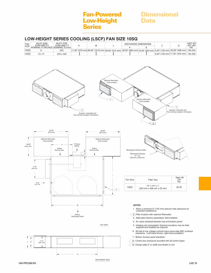
1. Allow a minimum 6" (152 mm) plenum inlet clearance for unducted installations.
2. Filter location with optional Attenuator.
3. Attenuator-factory assembled, field installed.
4. Air valve centered between top and bottom panel.
LOW-HEIGHT SERIES COOLING (LSCF) FAN SIZE 10SQ
36.00" (914 mm)48.00" (1219 mm) 38.00" (965 mm)
6. All high & low voltage controls have same-side NEC jumback clearance. (Left-hand shown, right-hand available.)
g gg g
AirflowPlenum Inlet
Field InstalledOptional Attenuator
edOptional Attenuator
Field InstalledOptional Attenuator
Field InstalledOptional Attenuator
L
H
2.
A
TOP VIEW
DISCHARGE VIEW
32.00"(813 mm) (813 mm)
32.00"
B
Rectangular Damper Detail
Rectangular Damper
(203 mm x 356 mm)8" x 14"
(457 mm)18.00"
DISCHARGE DIMENSIONS
10SQ
10SQ
SIZEFAN
H W LA
6.00" (152 mm)
4.00" (102 mm)B
C
20.00" (508 mm)
17.50" (445 mm)
DUNIT WT
(kg)WT LBS
PrimaryAirflow
D
Plenum InletAirflow
AirflowDischarge Outlet
W
NOMINAL Ø (INCHES)
8 x 14
8
INLET SIZEAVAILABILITY
NOMINAL Ø (mm)203
203 x 356
INLET SIZE
(254 mm x 406 mm x 25 mm)
Fan Size
10SQ
Atten WtFilter Size
10" x 16" x 1"
(kg)Lbs
8. Control box enclosure provided with all control types.
9. Flange adds 2" to width and length of unit.
7. Bottom Access panel standard.
Fan Controls located in EnclosureActuator, Controller and
8.Fan Controls located in Enclosure
8.
(127 mm)5.00"
17.50"(445 mm)
(267 mm)10.50"
120 (54)
20 (9)
130 (59)
9.

Fan-PoweredLow-HeightSeries
LHS 20 VAV-PRC008-EN
DimensionalData
AirflowPrimary
Plenum InletAirflow
DISCHARGE VIEW
DISCHARGE DIMENSIONS
18.00" (457 mm)
SIZEFAN
09SQ08SQ 26.00" (660 mm)
H W
40.00" (1016 mm)( )
LA B
C DUnit Wt
Lbs(kg)
Discharge Outlet
Airflow
TOP VIEW
09SQ6, 8 152, 203
8 x 14 203 x 355
AirValve
Field InstalledOptional Attenuator
Rectangular Damper Detail
W
H
L
Field InstalledOptional Attenuator
A
B
Rectangular Damper
(203 mm x 356 mm)8" x 14"
D
C
1.00"
(25 mm)
LOW-HEIGHT SERIES HOT WATER (LSWF) FAN SIZES 08SQ & 09SQ
Water
Coil
INLET SIZEINLET SIZE
NOMINAL ØAVAILABILITY
NOMINAL Ø (mm)
32.00"(813 mm)
(457 mm)18.00"
(254 mm x 254 mm x 25 mm)08SQ09SQ
Fan SizeAtten Wt
10" x 10" x 1"
Filter Size(kg)Lbs
NOTES:
1. Allow a minimum 6" (152 mm) plenum inlet clearance for unducted installations.
2. Flanged discharge outlet accepts up to a 1" (25 mm) duct flange.
gg
3. Bottom Access panel standard.
4. Control box enclosure provided with all control types.
5. Air valve centered between top and bottom panel.
6. Heating coil uninsulated. External insulation may be field supplied and installed as required.
gg
7. All high & low voltage controls have same-side NEC jumpback clearance. (Left-hand
g gg gshown, right-hand available.)
8. Flange adds 2" to width and length of unit.
Fan Controls located in EnclosActuator, Controller and
4.
Fan Controls located in EnclosureActuator, Controller and
4.
Fan Controls located in EnclosureActuator, Controller and
(445 mm)17.50"
(127 mm)5.00"
10.50"(267 mm)
6.80"(173 mm)
10 (4.5)
114 (52)105 (48)
8.

Fan-PoweredLow-HeightSeries
VAV-PRC008-EN LHS 21
DimensionalData
5. Heating coil uninsulated. External insulation may be field supplied and installed as required.
gg
NOTES:
1. Allow a minimum 6" (152 mm) plenum inlet clearance for unducted installations.
2. Filter location with optional Attenuator.
3. Attenuator-factory assembled, field installed.
4. Air valve centered between top and bottom panel.
LOW-HEIGHT SERIES HOT WATER (LSWF) FAN SIZE 10SQ
6. All high & low voltage controls have same-side NEC jumpback clearance. (Left-hand shown, right-hand available.)
g gg g
dator
dtor
Field InstalledOptional Attenuator
Field InstalledOptional Attenuator
L
2.
A
(173 mm)6.80"
TOP VIEW
DISCHARGE VIEW
32.00"(813 mm) (813 mm)
32.00"
Rectangular Damper Detail
Rectangular Damper
(203 mm x 356 mm)8" x 14"
(457 mm)18.00"
W
Discharge OutletAirflow
Plenum InletAirflow
DAirflowPrimary
Plenum InletAirflow
FAN
10SQ
10SQ
SIZE
36.00" (914 mm)11.00" (279 mm)
H
48.00" (1219 mm)
WDISCHARGE DIMENSIONS
LA B
D
6.00" (152 mm)
CUNIT WT
(kg)WT LBS
38.00" (965 mm)NOMINAL Ø (INCHES)
8 x 14
8
INLET SIZEAVAILABILITY
NOMINAL Ø (mm)
203 x 356
203
INLET SIZE
(445 mm)
(127 mm)5.00"
17.50"
B H
C
Actuator, Controller andFan Controls located in Enclosure
8.
Actuator, Controller andFan Controls located in Enclosure
8.
Actuator, Controller andFan Controls located in Enclosure
8.
(267 mm)10.50"
8. Control box enclosure provided with all control types.
7. Bottom Access panel standard.
146 (66)
10" x 16" x 1"(254 mm x 406 mm x 25 mm)10SQ
Fan Size
20 (9)
Filter Size Lbs(kg)
Atten Wt

Fan-PoweredLow-HeightSeries
LHS 22 VAV-PRC008-EN
DimensionalData
NOTES:
1. Location of coil connections is determined by facing air stream. L.H. coil connections shown, R.H. opposite.
2. Coil furnished with stub sweat connections.
3. Coils can be field-rotated for opposite connections. Note: Water inlet is always the bottom connection.
4. Access panel is standard.
18.00" (457 mm)
COIL
CONNECTIONFAN
SIZE
10SQ
08SQ .875" (22 mm) O.D. 7.75" (197 mm)
A B
1.50" (38 mm)
L
10.00" (254 mm)
H
6.80" (173 mm)
W
09SQ
38.00" (965 mm)
COIL INFORMATION FOR LOW-HEIGHT SERIES 1-ROW COIL
Fan Size
08SQ0.07 10.4(.28) (4.7)
INTERNALVOLUMEGAL (L)
OPERATINGWEIGHTLBS (KG)
09SQ
0.15 (.59) 16.4 (7.4)10SQ(25 mm)
(51 mm)2.00"
(198 mm)
ACCESS PANEL
3.40"(86 mm)
A
7.81"
INLETB
W
1.00"
AIR FLOW
B
A
H
AIR FLOW

Fan-PoweredLow-HeightSeries
VAV-PRC008-EN LHS 23
DimensionalData
INLETB
INLETA
ACCESS PANEL
AIR FLOW
10SQ
.875" (22 mm) O.D.
09SQ
08SQ
FANSIZE
COILCONNECTION
6.25" (159 mm)
A
2.00 (51 mm)
B
38.00" (965 mm)
18.00" (457 mm)
L
10.00" (254 mm)
H
6.75" (171 mm)
W
W
(86 mm)3.40"
(198 mm)7.81"
INTERNALVOLUMEGAL (L)
10SQ
08SQ09SQ
Fan Size
0.24
0.11
23.0
11.1
(.94)
(.45)
(10.4)
OPERATINGWEIGHTLBS (KG)
(5.0)
COIL INFORMATION FOR LOW-HEIGHT SERIES 2-ROW COIL
NOTES:
1. Location of coil connections is determined by facing air stream. L.H. coil connections shown, R.H. opposite.
2. Coil furnished with stub sweat connections.
3. Coils can be field-rotated for opposite connections. Note: Water inlet is always the bottom connection.
4. Access panel is standard.
AIR FLOW
H
B
A
(51 mm)2.00"
(25 mm)1.00"
L

Fan-PoweredLow-HeightSeries
LHS 24 VAV-PRC008-EN
DimensionalData
AirflowPrimary
Plenum InletAirflow
LOW-HEIGHT SERIES ELECTRIC HEAT (LSEF) FAN SIZES 08SQ & 09SQ
DISCHARGE VIEW
DISCHARGE DIMENSIONS
14.00" (356 mm)127, 152, 203
SIZEFAN
09SQ08SQ 5, 6, 8 26.00" (660 mm)11.00" (279 mm)
H W
40.00" (1016 mm)
L
9.00" (229 mm)A B
C DUnit Wt
Lbs(kg)
10" x 10" x 1"(254 mm x 254 mm x 25 mm)
Fan Size
08SQ
Filter Size
TOP VIEW
09SQ6, 8 152, 203
8 x 14 203 x 355
AirValve
Field InstalledOptional Attenuator
Rectangular Damper Detail
H
L
Field Installedtional Attenuator
B
09SQ
Rectangular Damper
(203 mm x 356 mm)8" x 14"
D
C
6.00" (152 mm)
4.00" (102 mm) 4.00" (102 mm)
4.50" (114 mm)
Discharge OutletAirflow
Electric
Heater
A
NOMINAL Ø (INCHES)AVAILABILITY
INLET SIZE
NOMINAL Ø (mm)AVAILABILITY
INLET SIZE
Atten Wt
(kg)Lbs
(813 mm)32.00"
(457 mm)18.00"
Actuator, Controller andFan Controls located in Enclosure
4.
Actuator, Controller andFan Controls located in Enclosure
4.
Actuator, Controller andFan Controls located in Enclosure
4.
NOTES:
1. Allow a minimum 6" (152 mm) plenum inlet clearance for unducted installations.
2. Flanged discharge outlet accepts up to 1" (25 mm) duct flange.
3. Bottom Access panel standard.
4. Control box enclosure provided with all control types.
5. Air valve centered between top and bottom panel.
6. Heating coil uninsulated. External insulation may be field supplied and installed as required.
7. All hight & low voltage controls have same-side NEC jumpback clearance. (Left-hand shown, right-hand available.)
8. Flange adds 2" to width and length of unit.
(508 mm)20.00"
17.50"(445 mm)
(127 mm)5.00"
(267 mm)10.50"
101 (45.8)
120 (54.4)( )
10 (4.5)
8.

Fan-PoweredLow-HeightSeries
VAV-PRC008-EN LHS 25
DimensionalData
5. Heating coil uninsulated. External insulation may be field supplied and installed as required.
gg
NOTES:
1. Allow a minimum 6" (152 mm) plenum inlet clearance for unducted installations.
2. Filter location with optional Attenuator.
3. Attenuator-factory assembled, field installed.
4. Air valve centered between top and bottom panel.
LOW-HEIGHT SERIES ELECTRIC (LSEF) FAN SIZE 10SQ
6. All high & low voltage controls have same-side NEC jumpback clearance. (Left-hand shown, right-hand available.)
g gg g
AirflowPlenum Inlet
Field InstalledOptional Attenuator
Field Installed
Field InstalledOptional Attenuator
Field InstalledOptional Attenuator
LW
H
(279 mm)11.00"
Discharge OutletAirflow
HeaterTer
min
al B
ox
24.00"(610 mm)
A
(203 mm)8.00"
TOP VIEW
DISCHARGE VIEW
32.00"(813 mm) (813 mm)
32.00"
B
Plenum Area
18.00"(457 mm)
Rectangular Dam
(203 mm x 356 mm)
Rectangular Damper8" x 14"
SIZE
10SQ
10SQ
FAN DISCHARGE DIMENSIONSLWH
36.00" (914 mm)48.00" (1219 mm)11.00" (279 mm)A
C D WT LBS
6.00" (152 mm)
B (kg)
UNIT WT
25.30" (643 mm)
C
AirflowPrimaryD
AirflowPlenum Inlet
NOMINAL Ø (mm)
INLET SIZE
NOMINAL Ø (INCHES)
8 x14
AVAILABILITY
8
AVAILABILITY
203 x 356
203
INLET SIZE
8. Control box enclosure provided with all control types.
9. Flange adds 2" to width and length of unit.
7. Bottom Access panel standard.
Fan Controls located in EnclosureActuator, Controller and
8.
Fan Controls located in EnclosureActuator, Controller and
8.
Fan Controls located in EnclosureActuator, Controller and
8.
(254 mm x 406 mm x 25 mm)
Fan Size
10SQ
Atten Wt (Qty 2)Filter Size
10" x 16" x 1"
(kg)Lbs
(127 mm)5.00"
17.50"(445 mm)
(26710
155 (70.3)
20 (9.1)9.

Fan-PoweredLow-HeightSeries
LHS 26 VAV-PRC008-EN
MechanicalSpecifications
MODELS LSCF, LSWF,and LSEFLow-height series fan-poweredterminal units.
LSCF – Cooling Only
LSWF – With Hot Water Coil
LSEF – With Electric CoilCASING22-gage galvanized steel. Hangerbrackets, bottom access, and plenuminlet filter are provided as standard.AGENCY LISTINGThe unit is UL and Canadian ULListed as a room air terminal unit.Control # 9N65.
ARI 880 Certified.INSULATION
1/2" (12.7 mm) Matte-facedInsulation—The interior surface of theunit casing is acoustically andthermally lined with ½-inch, 1.75 lb/ft3
(12.7 mm, 28.03 kg/m3) compositedensity glass fiber with a high-densityfacing of 4.0 lb/ft3 (64 kg/m3). Theinsulation R-Value is 1.9. The insulationis UL listed and meets NFPA-90A andUL 181 standards. There are noexposed edges of insulation (completemetal encapsulation).1" (25.4 mm) Matte-facedInsulation—The interior surface ofthe unit casing is acoustically andthermally lined with 1-inch, 1.55 lb/ft3
(25.4 mm, 24.8 kg/m3) compositedensity glass fiber with a high-densityfacing of 4.0 lb/ft3 (64 kg/m3). Theinsulation R-Value is 3.85. Theinsulation is UL listed and meets NFPA-90A and UL 181 standards. There areno exposed edges of insulation(complete metal encapsulation).1/2" (12.7 mm) Foil-facedInsulation—The interior surface ofthe unit casing is acoustically andthermally lined with ½-inch, 2.0 lb/ft3
(12.7 mm, 32.04 kg/m3) density glassfiber with foil facing. The insulationR-Value is 2.2. The insulation is ULlisted and meets NFPA-90A and UL 181standards as well as bacteriologicalstandard ASTM C 665. There are noexposed edges of insulation (completemetal encapsulation).1" (25.4 mm) Foil-facedInsulation—The interior surface ofthe unit casing is acoustically andthermally lined with 1-inch, 2.0 lb/ft3
(25.4 mm, 32.04 kg/m3) density glassfiber with foil facing. The insulationR-Value is 4.3. The insulation is UL
listed and meets NFPA-90A and UL 181standards as well as bacteriologicalstandard ASTM C 665. There are noexposed edges of insulation (completemetal encapsulation).1" (25.4 mm) Double-wallInsulation—The interior surface of theunit casing is acoustically andthermally lined with a 1-inch, 2.1 lb./ft3
(25.4 mm, 33.6 kg/m3) compositedensity glass fiber with high-densityfacing. The insulation R-value is 3.0. Theinsulation is UL listed and meets NFPA-90A and UL 181 standards. Theinsulation is covered by an interiorliner made of 26-gage galvanized steel.All wire penetrations are covered bygrommets. There are no exposededges of insulation (complete metalencapsulation).3/8" (9.5 mm) Closed-cellInsulation—The interior surface ofthe unit casing is acoustically andthermally lined with 3/8-inch, 4.4 lb/ft3
(9.5 mm, 40.0 kg/m3) closed-cellinsulation. The insulation is UL listedand meets NFPA-90A and UL 181standards. The insulation has anR-value of 1.4. There are no exposededges of insulation (complete metalencapsulation).PRIMARY AIR VALVE
Air Valve Round—The primary airinlet connection is an 18-gagegalvanized steel cylinder sized to fitstandard round duct. A multiple-point,averaging flow sensing ring isprovided with balancing taps formeasuring +/-5% of unit catalogedairflow. An airflow-versus-pressuredifferential calibration chart isprovided. The damper blade isconstructed of a closed-cell foam sealthat is mechanically locked betweentwo22-gage galvanized steel disks. Thedamper blade assembly is connectedto a cast zinc shaft supported by self-lubricating bearings. The shaft is castwith a damper position indicator. Thevalve assembly includes a mechanicalstop to prevent over-stroking. At 4.0 in.wg, air valve leakage does not exceed1% of cataloged airflow.Air Valve Rectangular—Inlet collar isconstructed of 22-gage galvanizedsteel sized to fit standard rectangularduct. An integral multiple-point,averaging flow-sensing ring providesprimary airflow measurement within +/-5% of unit cataloged airflow. Typicalinlet conditions: flex duct and 90° inletsto the damper. Damper is 22-gagegalvanized steel with polyolefin foam
seal. The damper blade assembly isconnected to a solid metal shaftsupported by self-lubricating bearings.The shaft is cast with a damperposition indicator. The valve assemblyincludes a mechanical stop to preventover-stroking. At 3.0 in. wg, air valveleakage does not exceed 44 cfm(21 L/s).
FAN MOTORPSC—Single-speed, direct-drive,permanent split capacitor type.Thermal overload protection provided.Motors will be designed specifically foruse with an open SCR. Motors will besingle-speed with standard SCR forspeed control. Motors willaccommodate anti-backward rotationat start up. Motor and fan assembly isisolated from terminal unit.
ECM—Electrically Commutated Motoris desinged for high-efficient operationwith over 70% efficiency throughoutthe operating range.FAN SPEED CONTROL
Variable Speed Control Switch(SCR)—The SCR speed control deviceis provided as standard and allows theoperator infinite fan speed adjustmentso the fan output may be modified toachieve exact cfm requirements.TRANSFORMER
The 50 VA transformer is factory-installed in the fan control box toprovide 24 VAC for controls.POWER DISCONNECT
The power disconnect is provided asstandard and allows the operator toturn the unit on or off by toggling tothe appropriate setting. This switchbreaks both legs of power to the fanand the electronic controls (ifapplicable). Not provided on LSEF withpneumatic controlsOUTLET CONNECTION
Flanged Connection—Arectangular opening on the unitdischarge to accept a 90° flangedductwork connection.FILTER
A 1" (25 mm) filter is provided on theplenum inlet and attaches to the unitwith a filter frame.
LSXFInlet 08Q 09SQ 10SQ
5" X6" X X8" X X X
8x14" X X
Fan–Inlet Combinations:

Fan-PoweredLow-HeightSeries
VAV-PRC008-EN LHS 27
MechanicalSpecifications
ACCESS PANELInternal access to unit is achievedthrough the removable bottom accesspanel.
HOT WATER COIL
Series Water Coils—factory-installedon the plenum inlet.
The coil has 1-row with 144 aluminum-plated fins per foot (.305 m) and, ifneeded, 2-row with 144 aluminum-plated fins per foot (.305 m). Full fincollars provided for accurate finspacing and maximum fin-tubecontact. The 3/8" (9.5 mm) OD seamlesscopper tubes are mechanicallyexpanded into the fin collars. Coils areproof tested at 450 psig (3102 kPa) andleak tested at 300 psig (2068 kPa) airpressure under water. Coil connectionsare brazed with left-hand configuration.
ELECTRIC HEAT COIL
The electric heater is a factory-providedand -installed, UL recognizedresistance open-type heater. It alsocontains a disc-type automatic pilotduty thermal primary cutout, andmanual reset load carrying thermalsecondary device. Heater elementmaterial is nickel-chromium. The heaterterminal box is provided with 7/8"(22 mm) knockouts for customer powersupply. Terminal connections areplated steel with ceramic insulators.Heater control access is on thedischarge side of the unit. All fan-powered units with electric reheat aresingle-point power connections.
ELECTRIC HEAT OPTIONS
Magnetic Contactor—An optionalelectric heater 24-volt contactor for usewith direct digital control (DDC) oranalog-electronic controls.
Mercury Contactor—An optionalelectric heater 24-volt contactor for usewith direct digital control (DDC) oranalog-electronic controls.
P.E. Switch with MagneticContactor—This optional switch andmagnetic contactor is for use withpneumatic controls.
P.E. Switch with MercuryContactor—This optional switch andmercury contactor is for use withpneumatic controls.
Airflow Switch—An optional airpressure device designed to disablethe heater when the system fan is off.
Power Fuse—If power fuse is chosenwith a unit with electric heat, then asafety fuse located in the line of powerof the electric heater to prevent powersurge damage to the electric heater.
Any electric heat unit with a calculatedMCA greater than or equal to 30 willhave a fuse provided
Disconnect Switch—An optionalfactory-provided door interlockingdisconnect switch on the heater controlpanel disengages primary voltage tothe terminal.
UNIT CONTROLS SEQUENCE OFOPERATIONThe controller will start and run the fancontinuously during the occupiedmode and intermittently during theunoccupied mode. Upon a further callfor heat, any hot water or electric heatassociated with the unit is enabled.
DIRECT DIGITAL CONTROLS
DDC Actuator—Trane 3-wire,24-VAC, floating-point control actuatorwith linkage release button. Torque is35 in-lb minimum and is non-springreturn with a 90-second drive time.Travel is terminated by end stops atfully-opened and -closed positions. Anintegral magnetic clutch eliminatesmotor stall.
Direct Digital Controller—Themicroprocessor based terminal unitcontroller provides accurate, pressure-independent control through the useof a proportional integral controlalgorithm and direct digital controltechnology. The controller, named theUnit Control Module (UCM), monitorszone temperature setpoints, zonetemperature and its rate of change,and valve airflow using a differentialpressure signal from the pressuretransducer. Additionally, the controllercan monitor either supply duct airtemperature or CO2 concentration viaappropriate sensors. The controller isprovided in an enclosure with 7/8"(22 mm) knockouts for remote controlwiring. A Trane UCM zone sensor isrequired.
DDC Zone Sensor—The UCMcontroller senses zone temperaturethrough a sensing element located inthe zone sensor. In addition to thesensing element, zone sensor optionsmay include an externally-adjustablesetpoint, communications jack for usewith a portable edit device, and an
override button to change the individualcontroller from unoccupied to occupiedmode. The override button has a cancelfeature that will return the system tounoccupied. Wired zone sensors utilizea thermistor to vary the voltage outputin response to changes in the zonetemperature. Wiring to the UCMcontroller must be 18- to 22-awg.twisted pair wiring. The setpointadjustment range is 50–88ºF (10–31°C).Depending upon the features availablein the model of sensor selected, thezone sensor may require from a 2-wireto a 5-wire connection. Wireless zonesensors report the same zoneinformation as wired zone sensors, butdo so using radio transmittertechnology. Therefore with wireless,wiring from the zone sensor to the UCMis unnecessary.
Digital Display Zone Sensor withLiquid Crystal Display (LCD)—Thedigital display zone sensor contains asensing element, which sends a signalto the UCM. A Liquid Crystal Display(LCD) displays setpoint or spacetemperature. Sensor buttons allow theuser to adjust setpoints, and allow spacetemperature readings to be turned on oroff. The digital display zone sensor alsoincludes a communication jack for usewith a portable edit device, and anoverride button to change the UCMfrom unoccupied to occupied. Theoverride button has a cancel feature,which returns the system tounoccupied mode.
Trane LonTalk—The controller isdesigned to send and receive data usingSCC LonTalk profile. Current unit statusconditions and setpoints may bemonitored and/or edited from any ofseveral LonTalk-compatible system-level controllers
ANALOG ELECTRONIC CONTROLS
Analog Actuator—A Trane 3-wire,24-VAC, floating-point control actuatorwith linkage release button. Torque is35 in-lb minimum and is non-springreturn with a 90-second drive time.Travel is terminated by end stops atfully-opened and -closed positions. Anintegral magnetic clutch eliminatesmotor stall.
Analog Electronic Controller—The controller consists of a circuit boardthat offers basic VAV unit operation andadditional override functions andoperates using 24 VAC power. The

Fan-PoweredLow-HeightSeries
LHS 28 VAV-PRC008-EN
MechanicalSpecifications
controller uses a capacitive typepressure transducer to maintainconsistent air delivery regardless ofsystem pressure changes. Theenclosure with 7/8" (22 mm) knockoutsfor remote control wiring. A Traneelectronic zone sensor is required.
Analog Electronic Thermostat—This single-temperature, wall-mountedelectronic device utilizes a thermistorto vary the voltage output in responseto changes in the zone temperature.Connections to the VAV unit circuitboard are made using standard three-conductor thermostat wire. Thesetpoint adjustment range is 63–85ºF(17–29°C). The sensor is available intwo models. One model has aconcealed, internally-adjustablesetpoint. The other model has anexternally-adjustable setpoint.
PNEUMATIC CONTROLS
Normally Open Actuator—Pneumatic 3 to 8 psig (20 to 55 kPa)spring-range pneumatic actuator.
3011 Pneumatic Volume Regulator(PVR)—The regulator is a thermostatreset velocity controller, whichprovides consistent air delivery within5% of cataloged flow down to 18% ofunit cataloged cfm, independent ofchanges in system static pressure.Factory-calibrated, field-adjustablesetpoints for minimum and maximumflows. Average total unit bleed rate,excluding thermostat, is 28.8 scim at20 psig (7.87 ml/min at 138 kPa) supply.
UNIT OPTIONS
Power Fuse (LSCF, LSWF)—Optional fuse is factory-installed in theprimary voltage hot leg.
HOT WATER VALVES
Two-Position Valve—The valve is afield-adaptable, 2-way or 3-wayconfiguration and ships with a cap tobe field-installed when configured as a2-way valve. All connections areNational Pipe Thread (NPT). The valvebody is forged brass with a stainlesssteel stem and spring. Upon demand,the motor strokes the valve. When theactuator drive stops, a spring returnsthe valve to its fail-safe position.
Flow Capacity – 1.17 CvOverall Diameter – ½" NPTClose-off Pressure – 30 psi (207 kPa)
Flow Capacity – 3.0 CvOverall Diameter – 3/4" NPTClose-off Pressure – 14.5 psi (100 kPa)
Flow Capacity – 6.4 CvOverall Diameter – 1" NPTClose-off Pressure – 9 psi (62 kPa)
Maximum Operating FluidTemperature – 203ºF (95ºC)
Maximum system pressure – 300 psi(2067 kPa). Maximum static pressure –300 psi (2067 kPa)
Electrical Rating – 7 VA at 24 VAC,6.5 Watts, 50/60 Hz
8 feet (2.44 m) of plenum rated wirelead is provided with each valve.
Proportional Water Valve—Thevalve is a field-adaptable, 2-way or 3-way configuration and ships with a capover the bottom port. This configuresthe valve for 2-way operation. For3-way operation, remove the cap. Thevalve is linear equal percentagedesign. The intended fluid is water orwater and glycol (50% maximumglycol). The actuator is a synchronousmotor drive. The valve is driven to apredetermined position by the UCMcontroller using a proportional plusintegral control algorithm. If power isremoved, the valve stays in its lastposition. The actuator is rated forplenum applications under UL 94-5Vand UL 873 standards.
Pressure and Temperature Ratings –The valve is designed and tested in fullcompliance with ANSI B16.15 Class250 pressure/temperature ratings,ANSI B16.104 Class IV control shutoffleakage, and ISA S75.11 flowcharacteristic standards.
Flow Capacity – 0.7 Cv, 2.2 Cv, 3.8 Cv,and 6.6 Cv
Overall Diameter – ½" NPT, ¾" NPT(6.6 Cv)
Maximum Allowable Pressure – 300psi (2068 kPa)
Maximum Operating FluidTemperature – 200ºF (93°C)
Maximum Close-off Pressure – 55 psi(379 kPa)
Electrical Rating – 6 VA at 24 VAC.
10 feet (3.05 m) of plenum rated22-gage wire for connection.Terminations are #6 stabs.