fatigue behavior of a quenched and tempered aisi 4340 ...alberto.pertuz.free.fr/article...
TRANSCRIPT

Fatigue behavior of a quenched and tempered AISI 4340 steel coated withan electroless Ni-P deposit
Y. GarceÂsa, H. SaÂncheza, J. BerrõÂosb, A. Pertuza, J. Chittyc, H. Hintermannd, E.S. Puchib,*
aSchool of Mechanical Engineering, Faculty of Engineering, Central University of Venezuela, Apartado Postal 47885, Los Chaguaramos,
Caracas 1045, VenezuelabSchool of Metallurgical Engineering and Materials Science, Faculty of Engineering, Central University of Venezuela, Apartado Postal 47885, Los
Chaguaramos, Caracas 1045, VenezuelacDepartment of Applied Mathematics, Faculty of Engineering, Central University of Venezuela, Apartado Postal 47885, Los Chaguaramos,
Caracas 1045, VenezueladFaculty of Sciences, University of NeuchaÃtel, NeuchaÃtel, Switzerland
Abstract
The fatigue life of a quenched and tempered AISI 4340 steel has been evaluated in three different conditions: (a) uncoated, (b) coated with
an electroless Ni-P (EN) deposit of a P content of approximately 12±14wt.%, as-deposited and (c) as-deposited, followed by a two-step post-
heat treatment (PHT): 473 K for 1 h plus 673 K for 1 h. The results indicate that plating the base steel with this kind of deposit leads to a
signi®cant reduction of the fatigue life of the material, particularly if the deposit is subjected to a subsequent PHT. Such a reduction has been
quanti®ed by determining the Basquin parameters from the fatigue life curves obtained for the uncoated, coated, coated and PHT substrates.
It has been shown that the fatigue life of the base steel can be reduced by 78% in the as-deposited condition and a 92% after a subsequent
PHT. The microscopic observation of the fracture surfaces of the samples indicate that the fatigue process is initiated at the surface of the
deposit and, subsequently, transferred to the substrate, with the assistance of the metallic bonding established at the deposit-substrate
interface. This belief is supported by the observation of some continuity of the fracture features between the coating and the substrate
under low alternating stresses. In the present study, the bonding between the EN deposit and the base steel was observed to be rather poor.
Extensive secondary cracking along the coating-substrate interface after fatigue testing as well as the complete separation of the deposit from
the substrate during tensile testing support this view. Such a behavior is believed to be related to the signi®cant difference that exists between
the elastic and plastic properties of the EN deposit and the base steel. Nonetheless, the slight degree of metallic bonding that remains after the
®rst stage of fatigue testing seems to be enough to allow the passage of the fatigue cracks, prior nucleated in the deposit, into the substrate. It
is therefore concluded that, in the present case, the EN deposit acts as a surface crack source or surface notch which decreases the fatigue life
of the coated material by reducing the crack nucleation stage. q 1999 Published by Elsevier Science Ltd. All rights reserved.
Keywords: Fatigue behavior; Plain carbon steels; Electroless Ni-P deposits; Fatigue cracks
1. Introduction
The fatigue and corrosion-fatigue behavior induced by
EN deposits on plain carbon steels of different carbon
content have been extensively investigated in previous
studies [1±7]. For example, Riedel [1] has reported an
increase in the fatigue life of two St 52 and AISI 1055 steels
when these have been coated with an EN deposit of 12% P
and subsequently post-heat treated (PHT). Izumi et al. [2]
have also reported an increase of about 20% in the fatigue
life of medium strength steels (UTS of approximately 440±
750 MPa) when the EN coating is in the as-deposited condi-
tion. However, after a PHT these authors have reported a
decrease which has been attributed to the precipitation of
Ni3P particles.
Puchi et al. [3] have also reported an increase in fatigue
life of both AISI 1010 and 1045 steels which is more
marked as the mechanical strength of the substrate material
decreases. Therefore, those steels with tensile strengths of
the order of 250±440 MPa could experience an increase in
fatigue life when coated with EN deposits, depending upon
the coating thickness and the predominant residual stresses
in the deposit itself. BerrõÂos et al. [5] have investigated the
effect of the coating thickness of an EN deposit on the
fatigue behavior of an annealed AISI 1045 steel. In this
study, 7±37 mm-thick EN coatings were deposited and
PHT at two different temperatures.
The only coatings that behaved similarly to the uncoated
Thin Solid Films 355±356 (1999) 487±493
0040-6090/99/$ - see front matter q 1999 Published by Elsevier Science Ltd. All rights reserved.
PII: S0040-6090(99)00673-2
www.elsevier.com/locate/tsf
* Corresponding author. Tel.: 158-2-662-8927; fax: 158-2-662-8927.
E-mail address: [email protected] (E.S. Puchi)

substrate was the 7 mm deposit PHT at 473 K for 1 h,
whereas all the other samples displayed a reduction in fati-
gue life. Particularly, for thicknesses ranging between 17±
37 mm it has been suggested that tensile residual stresses in
the coatings contribute to the observed fatigue behavior and
that such residual stresses could be associated with a rela-
tively low P content, crystallization of amorphous Ni and
precipitation of Ni3P particles. According to Riedel [1], the
P content of the deposit depends of the pH of the solution
employed as source of Ni ions. More speci®cally, it depends
on the molar ratio Ni21:(H2PO2)2, since as the concentration
of hypophosphite increases, the pH decreases and the P
increases. For a pH less than 5, the EN deposit could have
a P content of 10% or higher.
The studies of Parker and Shah [8] indicate that if the P
content of the deposit is greater than approximately 11±
12%, the residual stresses would be of a compressive nature.
In relation to high strength steels employed as substrate, Wu
and coworkers [9] have conducted an investigation on the
fatigue resistance of a 30CrMo steel (0.30 C, 1.09 Cr and
0.24 Mo) oil quenched from 1143 K and tempered at 893 K
for 3 h. The source of Ni ions was NiSO4 with a pH of 4.5.
The deposit was PHT a 473 K for 1.5 h. These authors found
a reduction in the fatigue limit of approximately 39% for the
plated substrate and a reduction of 20% when the substrate
was previously shot peened before plating.
It was also reported that the fatigue cracks initiated at the
interface between the coating and the substrate, and that in
the deposit some of the cracks were parallel to the stress
axis. The low fatigue strength of the coating was found to be
responsible for the decrease in the fatigue limit of the plated
steel. Zhang et al. [10] have also carried out three-point
bending fatigue tests on a 30CrMo steel coated with an
EN deposit of 43 mm thickness and 9.5 wt.% P. In this
investigation some of the samples were shot peened before
plating and some of the deposited specimens were PHT at
200, 400 and 6008C.
The residual stresses in the coatings were determined by
means of the bent strip method and it was observed that for
all the conditions investigated such stresses remained
compressive after annealing, but decreased with increasing
annealing temperature. Also, shot peening before plating
was observed to increase the compressive residual stress
within the coatings. Regarding the in¯uence of EN deposits
on the fatigue limit of the material, it was determined that
such coatings reduced this property in comparison with the
unplated substrate.
The decrease in fatigue strength was observed to be less
marked for the shot peened specimens but became signi®-
cantly higher as the PHT temperature increased. In relation
to the fractographic analysis of the plated samples, it was
reported that without the application of shot peening, the
fatigue cracks initiated at the surface of the specimens, lead-
ing to the fatigue failure of the coating. On the contrary,
when the samples were shot peened previously to the coat-
ing deposition, the crack initiation sites were displaced to
the coating±substrate interface. The work conducted by
Zhang et al. [10] allowed the conclusion that the fatigue
properties of this material, when it is coated with EN depos-
its, depends primarily on the fatigue resistance of the coat-
ing itself.
Thus, the present investigation has been conducted in
order to study the fatigue behavior, above the fatigue
limit, of an AISI 4340 steel which has been oil quenched
and tempered prior to plating at industrial scale with an EN
deposit of 24 mm in thickness and a P content ranging
between 12 and 14%.
2. Experimental techniques
The present investigation has been carried out with
samples of an AISI 4340 steel with the following composi-
tion (%wt): 0.34 C, 0.50 Mn, 0.30 Si, 1.5 Cr, 0.20 Mo and
1.50 Ni. This alloy is widely employed in the manufacture
of automotive crankshafts and rear axle shafts, aircraft
crankshafts, connecting rods, propeller hubs, gears, drive
shafts, landing gear parts and heavy duty parts of rock drills.
The material was provided as bars of approximately 16 mm
diameter and 6 m length. Such bars were cut to pieces of
approximately 120 mm length for machining tensile speci-
mens and of 90 mm length for machining the fatigue
samples. Both type of specimens had a gage diameter of
6.35 mm, gage length of 12.7 mm, ®llet radius of 25.4
mm and shoulder diameter of 12.7 mm, according to the
ASTM standard E 606.
The alloy was already provided in the quenched and
tempered condition. The specimens were subsequently
ground with successive SiC papers grit 600±1200 and
polished mechanically. Fifty-six of these samples were
degreased in a 5% HCl solution at 348±353 K for 7 min,
rinsed again in distilled water, rinsed in a sodium bicarbo-
nate (100 g per liter) solution and rinsed in water. The
deposition was conducted industrially employing a bath
composed of 30 g/l nickel sulphate, 30 g/l sodium hypopho-
sphite, 35 g/l malic acid, 1.5 ppm lead sulphate, 10 g/l
succinic acid and a stabilizer.
During deposition the pH was maintained at approxi-
mately 5, at a mean temperature of about 358 K. The deposi-
tion rate was of approximately 12 mm/h and the process was
conducted for 2 h which allowed a thickness of about 24 mm
to be achieved. Such thicknesses were corroborated by
means of the ball cratering technique (Calotest, CSEM)
and image analysis (LECO 500). Twenty-four of the depos-
ited samples were PHT in an argon atmosphere following a
two-step process that involved an initial treatment at 473 K
for 1 h and a subsequent heating at 673 K also for 1 h. The
chemical analysis of such deposits was determined by
means of SEM techniques (Hitachi S-2400) with EDS facil-
ities.
The observations were conducted at a constant potential
of 20 kV. Tensile tests were carried out on a computer-
Y. GarceÂs et al. / Thin Solid Films 355±356 (1999) 487±493488

controlled servohydraulic machine (Instron 8502) at a cross
head speed of 10 mm/min. At least three samples were
employed for characterizing the monotonic mechanical
properties of both the coated and uncoated substrate. Fati-
gue tests were carried out under rotating bending conditions
(Fatigue Dynamics, RBF-200) at a frequency of 50 Hz and
alternating stresses of 590, 611, 634 and 663 MPa, for the
uncoated substrate and the specimens in the as-deposited
condition, which corresponds to 80, 83, 86 and 90% of the
yield stress of the unplated substrate.
For the coated and PHT samples the tests were conducted
at 442, 516, 590 and 663 MPa, corresponding to 60, 70, 80
and 90% of the base steel. A total of 40 samples were
employed for evaluating the fatigue properties of the
uncoated substrate, 28 for the coated material and 28 for
the coated and PHT samples, which exceeds the minimum
number of specimens required in S-N testing for reliability
data according to the ASTM standard 739 (12±24 samples).
Thus, the testing procedure followed in the present work
allowed a replication greater than 80%. In order to make
possible a meaningful comparison of the fatigue life of the
coated and uncoated specimens, all the samples were
mechanically prepared in order to have similar polished
surfaces before testing.
The fracture surfaces of the samples were examined by
means of SEM techniques, particularly in relation to the
initiation of fatigue cracks and the different stages of their
propagation.
3. Results and discussion
3.1. Characteristics of the deposit
Fig. 1 illustrates the typical microstructure of the
substrate evaluated on the scanning electron microscope.
The presence of a large number of relatively coarse marten-
site plates together with carbides, visible as small particles
which constitute a typical tempered martensite structure,
can be observed. On the other hand, Fig. 2 shows a view
of the interface between the EN coating and substrate prior
to fatigue testing, illustrating the deposition of an apparently
uniform coating with satisfactory adhesion characteristics.
The evaluation of the coated material during tensile testing
and the observation of the fracture surfaces of the specimens
after fatigue testing however, would indicate otherwise.
As it has already been mentioned, the coating thickness
was corroborated by means of the ball cratering technique,
optical microscopy and scanning electron microscopy,
which allowed to determine a mean value of approximately
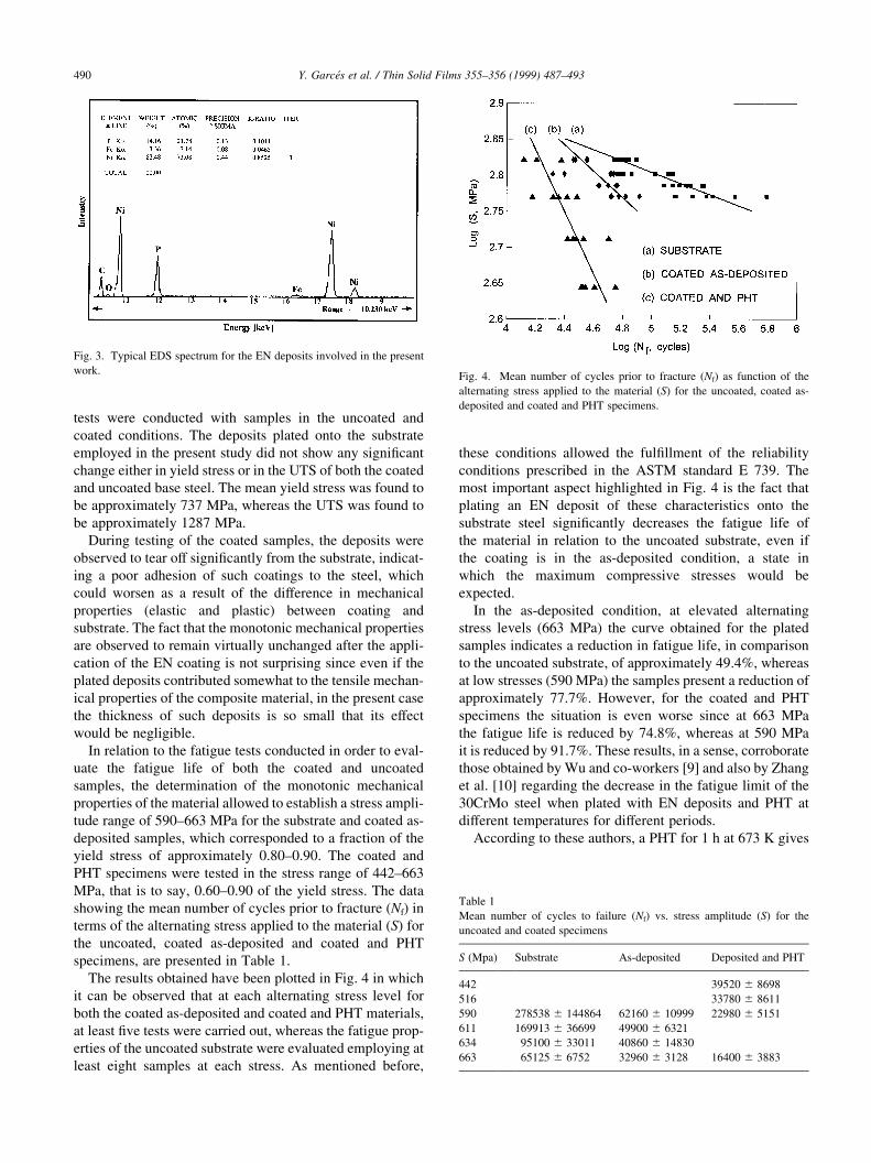
24 mm. As shown in Fig. 3, the EDS analyses conducted on
the deposit allowed to determine that the P content ranged
between 12 and 14wt.%. As has already been pointed out,
Parker and Shah [8] conducted an investigation concerning
the effect of the P content of an EN deposit on the residual
stresses within the coating. Accordingly, for a P content of
the order of that present in the samples under examination,
the residual stresses in the coatings are expected to be of a
compressive nature.
This fact would be in agreement with the ®ndings of Wu
et al. [9] and Zhang et al. [10], who also reported compres-
sive residual stresses of the order of 80 MPa in the coatings
deposited and subsequently PHT at 473 K for 1 h, even
though the P content of such deposits was lower
(9.5wt.%) than that contained in the coated specimens
employed in the present study, which also were in the as-
deposited condition.
3.2. Evaluation of mechanical properties
In order to evaluate if this particular deposit had any
in¯uence on the monotonic mechanical properties of the
composite coating-substrate material, a number of tensile
Y. GarceÂs et al. / Thin Solid Films 355±356 (1999) 487±493 489
Fig. 1. SEM photomicrograph illustrating a typical microstructure of the
substrate. A large number of relatively coarse martensite plates (M) and
carbide particles, visible as small white particles, can be observed.
Fig. 2. SEM view of the interface between the EN coating (D) and substrate
(S) previous to fatigue testing. The deposit seems to be uniform and has
apparently satisfactory adhesion characteristics due to the absence of visi-
ble cracks along the interface.
tests were conducted with samples in the uncoated and
coated conditions. The deposits plated onto the substrate
employed in the present study did not show any signi®cant
change either in yield stress or in the UTS of both the coated
and uncoated base steel. The mean yield stress was found to
be approximately 737 MPa, whereas the UTS was found to
be approximately 1287 MPa.
During testing of the coated samples, the deposits were
observed to tear off signi®cantly from the substrate, indicat-
ing a poor adhesion of such coatings to the steel, which
could worsen as a result of the difference in mechanical
properties (elastic and plastic) between coating and
substrate. The fact that the monotonic mechanical properties
are observed to remain virtually unchanged after the appli-
cation of the EN coating is not surprising since even if the
plated deposits contributed somewhat to the tensile mechan-
ical properties of the composite material, in the present case
the thickness of such deposits is so small that its effect
would be negligible.
In relation to the fatigue tests conducted in order to eval-
uate the fatigue life of both the coated and uncoated
samples, the determination of the monotonic mechanical
properties of the material allowed to establish a stress ampli-
tude range of 590±663 MPa for the substrate and coated as-
deposited samples, which corresponded to a fraction of the
yield stress of approximately 0.80±0.90. The coated and
PHT specimens were tested in the stress range of 442±663
MPa, that is to say, 0.60±0.90 of the yield stress. The data
showing the mean number of cycles prior to fracture (Nf) in
terms of the alternating stress applied to the material (S) for
the uncoated, coated as-deposited and coated and PHT
specimens, are presented in Table 1.
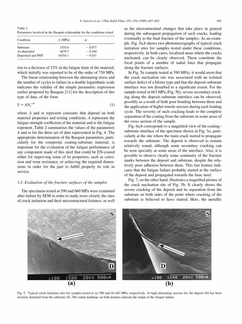
The results obtained have been plotted in Fig. 4 in which
it can be observed that at each alternating stress level for
both the coated as-deposited and coated and PHT materials,
at least ®ve tests were carried out, whereas the fatigue prop-
erties of the uncoated substrate were evaluated employing at
least eight samples at each stress. As mentioned before,
these conditions allowed the ful®llment of the reliability
conditions prescribed in the ASTM standard E 739. The
most important aspect highlighted in Fig. 4 is the fact that
plating an EN deposit of these characteristics onto the
substrate steel signi®cantly decreases the fatigue life of
the material in relation to the uncoated substrate, even if
the coating is in the as-deposited condition, a state in
which the maximum compressive stresses would be
expected.
In the as-deposited condition, at elevated alternating
stress levels (663 MPa) the curve obtained for the plated
samples indicates a reduction in fatigue life, in comparison
to the uncoated substrate, of approximately 49.4%, whereas
at low stresses (590 MPa) the samples present a reduction of
approximately 77.7%. However, for the coated and PHT
specimens the situation is even worse since at 663 MPa
the fatigue life is reduced by 74.8%, whereas at 590 MPa
it is reduced by 91.7%. These results, in a sense, corroborate
those obtained by Wu and co-workers [9] and also by Zhang
et al. [10] regarding the decrease in the fatigue limit of the
30CrMo steel when plated with EN deposits and PHT at
different temperatures for different periods.
According to these authors, a PHT for 1 h at 673 K gives
Y. GarceÂs et al. / Thin Solid Films 355±356 (1999) 487±493490
Fig. 3. Typical EDS spectrum for the EN deposits involved in the present
work.
Table 1
Mean number of cycles to failure (Nf) vs. stress amplitude (S) for the
uncoated and coated specimens
S (Mpa) Substrate As-deposited Deposited and PHT
442 39520 ^ 8698
516 33780 ^ 8611
590 278538 ^ 144864 62160 ^ 10999 22980 ^ 5151
611 169913 ^ 36699 49900 ^ 6321
634 95100 ^ 33011 40860 ^ 14830
663 65125 ^ 6752 32960 ^ 3128 16400 ^ 3883
Fig. 4. Mean number of cycles prior to fracture (Nf) as function of the
alternating stress applied to the material (S) for the uncoated, coated as-
deposited and coated and PHT specimens.
rise to a decrease of 52% in the fatigue limit of the material,
which initially was reported to be of the order of 750 MPa.
The linear relationship between the alternating stress and
the number of cycles to failure in a double logarithmic scale
indicates the validity of the simple parametric expression
earlier proposed by Basquin [11] for the description of this
type of data, of the form
S � AN2mf �1�
where A and m represent constants that depend on both
material properties and testing conditions. A represents the
fatigue strength coef®cient of the material and m the fatigue
exponent. Table 2 summarizes the values of the parameters
A and m for the three set of data represented in Fig. 4. The
appropriate determination of the Basquin parameters, parti-
cularly for the composite coating-substrate material, is
important for the evaluation of the fatigue performance of
any component made of this steel that could be EN-coated
either for improving some of its properties, such as corro-
sion and wear resistance, or achieving the required dimen-
sions in order for the part to ful®ll properly its role in
service.
3.3. Evaluation of the fracture surfaces of the samples
The specimens tested at 590 and 660 MPa were examined
after failure by SEM in order to study more closely the sites
of crack initiation and their microstructural features, as well
as the microstructural changes that take place in general
during the subsequent propagation of such cracks, leading
eventually to the ®nal fracture of the samples. As an exam-
ple, Fig. 5a,b shows two photomicrographs of typical crack
initiation sites for samples tested under these conditions,
respectively. In both cases, localized areas where the cracks
nucleated, can be clearly observed. These constitute the
focal points of a number of radial lines that propagate
along the fracture surfaces.
In Fig. 5a (sample tested at 590 MPa), it would seem that
the crack nucleation site was associated with an isolated
surface defect of a blister type and that the deposit-substrate
interface was not disturbed to a signi®cant extent. For the
sample tested at 663 MPa (Fig. 5b), severe secondary crack-
ing along the deposit±substrate interface can be observed,
possibly as a result of both poor bonding between them and
the application of higher tensile stresses during each loading
cycle. The severity of such cracking leads to the complete
separation of the coating from the substrate in some areas of
the cross section of the sample.
Fig. 6a,b corresponds to a magni®ed view of the coating±
substrate interface of the specimen shown in Fig. 5a, parti-
cularly at the site where the main crack started to propagate
towards the substrate. The deposit is observed to remain
relatively sound, although some secondary cracking can
be seen specially at some areas of the interface. Also, it is
possible to observe clearly some continuity of the fracture
marks between the deposit and substrate, despite the rela-
tively poor adhesion between them. This last feature indi-
cates that the fatigue failure probably started at the surface
of the deposit and propagated towards the base steel.
Fig. 7, on the other hand, illustrates a magni®ed picture of
the crack nucleation site of Fig. 5b. It clearly shows the
severe cracking of the deposit and its separation from the
substrate on both sides of the point where cracking of the
substrate is believed to have started. Here, the metallic
Y. GarceÂs et al. / Thin Solid Films 355±356 (1999) 487±493 491
Table 2
Parameters involved in the Basquin relationship for the conditions tested
Condition A (MPa) m
Substrate 1555.6 2 0.077
As-deposited 4479.7 2 0.184
Deposited and PHT 44354.1 2 0.431
Fig. 5. Typical crack initiation sites for samples tested at (a) 590 and (b) 663 MPa, respectively. At high alternating stresses (b), the deposit (D) has been
severely detached from the substrate (S). The radial markings on both pictures indicate the origin of the fatigue failure.

bonding between deposit and substrate is apparently main-
tained to some degree, which again indicates that the possi-
ble failure mechanism should be the passage of fatigue
cracks from the coating to the substrate. Therefore, cracks
would be formed at the surface of the deposit, propagate
through it leading to its fracture in some localized areas and
®nally transferred to the substrate in a region in which the
metallic bonding between the coating and the substrate is
still preserved.
Thus, even though the deposit would be under compres-
sive residual stresses due to its P content, its lower mechan-
ical strength in comparison with the substrate material leads
to the its prior failure with the consequent transfer of the
propagating cracks to the substrate. Hence, the coating actu-
ally operates as a fatigue crack source or surface stress
concentration which becomes very effective even if the
adherence of the deposit to the substrate is rather poor, as
in the present case. This mechanism would explain the
Y. GarceÂs et al. / Thin Solid Films 355±356 (1999) 487±493492
Fig. 6. (a) Magni®ed view of the coating-substrate interface of the specimen shown in Fig. 5a. (b) Magni®ed view of the coating-substrate interface of the
specimen shown in (a). The coating has been identi®ed as (D) and the substrate as (S). Continuity of the fracture features between the coating and substrate can
be clearly observed, as well as some secondary cracking along the interface.
Fig. 7. Magni®ed picture of the crack nucleation site of Fig. 5b. Severe cracking (C) of the deposit (D) and its separation from the substrate (S) can be clearly
observed. The main crack has propagated from the deposit into the substrate.

reduction in fatigue life observed for the coated specimens
in comparison with the uncoated samples tested at the same
alternating stresses.
These features are consistent with the previous ®ndings of
Zhang et al. [10] and Pertuz and co-workers [7], who were
able to observe fatigue marks in EN deposits plated onto
different steels as substrates. Such observations support the
view that if the mechanical strength of the substrate is
greater than that of the EN deposit or similar to it, the coat-
ing is bound to undergo fatigue failure before the substrate
and to transfer the fatigue cracks to it, giving rise to a reduc-
tion in its fatigue strength. If, however the fatigue strength
of the deposit is higher than that of the substrate, it is possi-
ble to observe an improvement in its fatigue performance, as
it has been reported by Puchi and co-workers [3] for an EN
deposit on AISI 1010 steel.
4. Conclusions
Plating of a quenched and tempered AISI 4340 with EN
deposits leads to a signi®cant reduction in the fatigue life of
the material. Such a reduction, at a stress amplitude of 590
MPa, can achieve up to approximately 78% if the coating is
in the as-deposited condition and 92% after a PHT such as
the one explored in the present work. Thus, according to the
present results, the reduction in fatigue life for this material
when coated with this kind of deposits is much more signif-
icant than previously reported. It has been shown that such a
decrease in fatigue performance occurs as a result of the
passage of fatigue cracks form the coating to the substrate,
a process which is believed to be assisted by the metallic
bonding established between them. The continuity of certain
fracture features between coating and substrate observed
from the analysis of some fracture surfaces supports this
view.
In the present case, due to the signi®cant difference that
exists between the elastic and plastic properties of coating
and substrate, the adherence of the deposit to the base steel
is rather poor. This conclusion is supported by the observa-
tion of extensive secondary cracking along the deposit±
substrate interface after fatigue testing and the actual
separation of the coating from the base steel during tensile
testing. Nevertheless, such degree of adherence is found to
be enough to allow the transfer of cracks from the coating to
the substrate.
Thus, it is concluded that due to the relatively lower
fatigue properties of the EN coating in comparison with
the substrate, the deposit actually operates as a source of
surface fatigue cracks, i.e. as a surface notch capable of
imparting a signi®cant reduction to the fatigue properties
of the substrate by reducing the time required for the nuclea-
tion of cracks. Coating of strong and tough substrates with
weaker deposits in order to impart wear and/or corrosion
resistance can thus lead to the fatigue failure of the compo-
nent prior to expected. Therefore, mechanical design under
conditions of high cycle fatigue should be based on the
Basquin parameters of the fatigue life curve of the coated
material rather than that determined for the uncoated
substrate.
Acknowledgements
This investigation has been conducted with the ®nancial
support of the Venezuelan National Council for Scienti®c
and Technological Research (CONICIT) through the project
LAB-97000644. J.A. BerrõÂos is deeply grateful to the Orga-
nization of the American States for the ®nancial support
received through the Multinational Material Project. He is
also grateful to the School of Mechanical Engineering of the
University of El Salvador.
References
[1] W. Riedel, Electroless Nickel Plating, Vol 48, ASM International,
Metals Park, OH, 1991, pp. 48±181.
[2] H. Izumi, H. Sunada, Y. Kondo, J. Soc. Mater. Sci. Japan 24 (1975)
320.
[3] E.S. Puchi, M.H. Staia, H. Hintermann, A. Pertuz, J.A. Chitty, Thin
Solid Films 290±291 (1996) 370.
[4] J.A. Chitty, M.H. Staia, A. Pertuz, H. Hintermann, E.S. Puchi, Thin
Solid Films 308±309 (1997) 430.
[5] J.A. BerrõÂos, M.H. Staia, E.C. HernaÂndez, H. Hintermann, E.S. Puchi,
Surf. Coat. Technol. 108±109 (1998) 466.
[6] J.A. Chitty, A. Pertuz, H. Hintermann, E.S. Puchi, J. Mater. Eng.
Perform. (1999).
[7] A. Pertuz, J.A. Chitty, H. Hintermann, E.S. Puchi, J. Mater. Eng.
Perform. (1999).
[8] K. Parker, H. Shah, Plating 58 (1971) 230.
[9] Y. Wu, Y. Zhang, M. Yao, Plat. Surf. Finish. (1995) 83.
[10] Y.Z. Zhang, Y.Y. Wu, M. Yao, J. Mater. Sci. Lett. 15 (1996) 1364.
[11] O.H. Basquin, Proc. ASTM 10 (2) (1910) 625.
Y. GarceÂs et al. / Thin Solid Films 355±356 (1999) 487±493 493