fatigue design of a mechanically biocompatible lattice for
TRANSCRIPT

Available online at www.sciencedirect.com
www.elsevier.com/locate/jmbbm
j o u r n a l o f t h e m e c h a n i c a l b e h a v i o r o f b i o m e d i c a l m a t e r i a l s 2 2 ( 2 0 1 3 ) 6 5 – 8 3
1751-6161/$ - see frohttp://dx.doi.org/10.1
nCorresponding autE-mail addresses1Present address
Canada H3A 2K6.
Research Paper
Fatigue design of a mechanically biocompatible latticefor a proof-of-concept femoral stem
Sajad Arabnejad Khanoki, Damiano Pasinin,1
Mechanical Engineering Department, McGill University Montreal, QC, Canada H3A 2K6
a r t i c l e i n f o
Article history:
Received 26 October 2012
Received in revised form
26 February 2013
Accepted 3 March 2013
Available online 16 March 2013
nt matter & 2013 Elsevier016/j.jmbbm.2013.03.002
hor. Tel.: þ1 514 398 6295;: sajad.arabnejadkhanoki@: Room 372, MacDonald
a b s t r a c t
A methodology is proposed to design a spatially periodic microarchitectured material for a two-
dimensional femoral implant under walking gait conditions. The material is composed of a gradedlattice with controlled property distribution that minimizes concurrently bone resorption and interfacefailure. The periodic microstructure of the material is designed for fatigue fracture caused by cyclicloadings on the hip joint as a result of walking. The bulk material of the lattice is Ti6AL4V and itsmicrostructure is assumed free of defects. The Soderberg diagram is used for the fatigue design undermultiaxial loadings. Two cell topologies, square and Kagome, are chosen to obtain optimized propertygradients for a two-dimensional implant. Asymptotic homogenization (AH) theory is used to addressthe multiscale mechanics of the implant as well as to capture the stress and strain distribution at boththe macro and the microscale. The microstress distribution found with AH is also compared with thatobtained from a detailed finite element analysis. For the maximum value of the von Mises stress, weobserve a deviation of 18.6% in unit cells close to the implant boundary, where the AH assumption of
spatial periodicity of the fluctuating fields ceases to hold.In the second part of the paper, the metrics of bone resorption and interface shear stress are used to
benchmark the graded cellular implant with existing prostheses made of fully dense titanium implant.The results show that the amount of initial postoperative bone loss for square and Kagome latticeimplants decreases, respectively, by 53.8% and 58%. In addition, the maximum shear interface failure atthe distal end is significantly reduced by about 79%.
A set of proof-of-concepts of planar implants have been fabricated via Electron BeamMelting (EBM)to demonstrate the manufacturability of Ti6AL4V into graded lattices with alternative cell size. Opticalmicroscopy has been used to measure the morphological parameters of the cellular microstructure,including cell wall thickness and pore size, and compared them with the nominal values. No sign offracture or incomplete cell walls was observed, an assessment that shows the satisfactory metallurgical
bond of cell walls and the structural integrity of the implants.& 2013 Elsevier Ltd. All rights reserved.
1. Introduction
An orthopaedic hip implant is expected to support dynamic forcesgenerated by human activities. To avoid progressive and localized
Ltd. All rights reserved.
fax: þ1 514 398 7365.mail.mcgill.ca (S. ArabnejadEngineering Building, Me
damage caused by daily cyclic loading, the prosthesis is to be designedfor fatigue under high cycle regime. Recently, a methodology has beendeveloped to design a novel hip implant made of a cellular materialwith a periodic microarchitecture (Khanoki and Pasini, 2012). In
Khanoki), [email protected] (D. Pasini).chanical Engineering Department, McGill University, Montreal, QC,

j o u r n a l o f t h e m e c h a n i c a l b e h a v i o r o f b i o m e d i c a l m a t e r i a l s 2 2 ( 2 0 1 3 ) 6 5 – 8 366
contrast to current hip replacement implants typically made out of afully solid material which can be coated with a porous layer, thisimplant is completely porous with a lattice microstructure displayinggraded property distribution. The advantage of controlling themicroarchitecture is twofold. First, the overall implant can bedesigned to be more compliant, which reduces stress shielding andbone resorption (Behrens et al., 2008; Glassman et al., 2006; Huiskeset al., 1992; Pettersen et al., 2009). Second, the material porosity canbe optimized to also reduce bone-implant interface stresses, therebylowering implant micromotion. Although encouraging, these resultshave been obtained by applying a static loading regime to theimplant, thus neglecting the impact of cyclic loading that generallyboosts the risk of fatigue failure.
In literature, there are several experimental and numericalstudies focusing on the fatigue analysis of hip implants (Baleaniet al., 1999; Hedia et al., 1996; Kayabasi and Ekici, 2007; Li et al.,2002; Nganbe et al., 2011; Ploeg et al., 2009; Raimondi andPietrabissa, 1999; Senalp et al., 2007). For example, fatigue loadingconditions, ISO 7206/3, have been applied to a hip stem to predictits elastic stress via large deflection finite element analysis (Ploeget al., 2009). It has been demonstrated via experiments that thehigh cycle fatigue-life of hip stems can be adequately predicted byusing alternative fatigue theories, such as Morrow, Smith–Wat-son–Topper (SWT), and Goodman. The Soderberg theory has alsobeen used to design a cemented implant for infinite life; theresults have been proved to be accurate although more conserva-tive than those obtained with Goodman and Gerber theories(Hedia et al., 1996; Kayabasi and Ekici, 2007).
Among the biocompatible materials used for reconstructiveorthopaedics, porous tantalum has been recently proved to beeffective in facilitating bone ingrowth. For this reason, poroustantalum has been lately the object of studies aiming at characteriz-ing its fatigue fracture mechanisms (Sevilla et al., 2007; Zardiackaset al., 2001). Similar to open cellular foams, porous tantalum has arandom cellular microstructure which is typically imparted by themanufacturing process, involving a chemical deposition of puretantalum on carbon skeleton (Bobyn et al., 2004; Murr et al., 2010,2009). Due to its pore structure, the fracture propagation of poroustantalum under fatigue has been observed similar to that of open-cell foams (Sevilla et al., 2007; Zardiackas et al., 2001; Zhou andSoboyejo, 2004). It has been observed that the bending dominatedfailure mode of the unit cell (Gibson, 2005; Liu and Du, 2011;Vigliotti and Pasini, 2012) at the cell joints nucleates cracks thatpropagate throughout a strut until the final break (Li et al., 2012;Sevilla et al., 2007; Zardiackas et al., 2001). The joints are indeed theweakest parts of a cellular material, because stress peaks localize inthose regions and thus severely reduce fatigue strength. However, ifthe geometry of the cell joints, i.e. the locations where the strutsconverge, is designed to level out any curvature discontinuity (Abadet al., 2012), then the joint strength can be significantly increased,thereby improving the fatigue strength of the cellular material.
While several analytic methods have been proposed to studythe fatigue life of cellular structures (Cote et al., 2006; Côté et al.,2007a, 2007b; Huang and Liu, 2001a, b; Huang and Lin, 1996;Olurin et al., 2001), the majority fail to accurately capture the realstress distribution generated in the lattice cells (Simone andGibson, 1998). To overcome this problem, more recently a fatiguedesign methodology has been introduced to model the elastic–plastic behavior of cellular materials, and used to generate fatiguedesign diagrams for cellular materials (Abad et al., 2012). The
method focuses on uni-axial and shear loading for relative densityρ≤0:3.
In this paper, the method of Abad et al. (2012) is first extendedto account for multiaxial loadings of cellular materials underinfinite fatigue life. The approach is then applied to the fatiguedesign of a planar proof-of-concept hip implant that is loadedunder cycling forces of walking. Two representative cell topologiesare selected to design the hip implant: the square lattice, which is abending dominated behaviour, and the Kagome cell, whose maindeformation is caused by the strut stretching. The results obtainedin this paper are numerically verified through the multilevelmethod for damage analysis (Ghosh et al., 2001; Raghavan andGhosh, 2004). The performance of the two lattice implants iscompared in terms of bone resorption, interface stress, andmechanical strength. Finally, 2D proof-of-concepts of gradedcellular implants with a square cell are fabricated to assess themanufacturability of the lattice microarchitecture.
2. Fatigue analysis of cellular materials
The deformation and failure mechanisms of a structure withheterogeneous material can occur at both macro and microscopiclength scales. Experimental studies have shown that a cellularmaterial under repetitive loading develop cracks at the microscalein regions with high stress concentration, from which fracturepropagates throughout the strut cross sections (Sevilla et al., 2007;Zardiackas et al., 2001; Zhou and Soboyejo, 2004). Since themicromechanisms of deformation and fracture play a crucial rolein the fatigue resistance of a cellular material, it is essential in thedesign of a cellular component to capture and account for themicroscopic stress and strain distribution. Here, we resort toAsymptotic Homogenization (AH) theory to determine the homo-genized properties of the cellular material and capture the micro-scopic stress and strain distribution via the analysis of arepresentative volume element (RVE). The underlying assumptionof AH is the periodicity of RVE and field quantities at macro andmicroscopic scales. AH method has been widely used in multiscaleanalysis of composite materials (Kalamkarov et al., 2009; Kanoutéet al., 2009), topology optimization (Bendsøe and Kikuchi, 1988;Bendsøe and Sigmund, 2003; Díaaz and Kikuchi, 1992; Guedes andKikuchi, 1990; Hassani and Hinton, 1998; Suzuki and Kikuchi, 1991),and hierarchical design of materials and structures (Coelho et al.,2008, 2011; Gonçalves Coelho et al., 2011; Rodrigues et al., 2002).
Recently, AH has been also used to propose a computationalprocedure for the fatigue design of periodic cellular materials(Abad et al., 2012). Yield and ultimate strength of lattice materialshave been determined for relative density ρ≤0:3, and used toconstruct modified Goodman diagrams of selected lattices underuni-axial and shear loading. This method is here extended toconstruct the Soderberg fatigue diagram for fatigue failure analysisof cellular structures under multiaxial loading conditions for thewhole range of relative density. Here, we assume the specimen to befree of defects, such as scratches, notches and nicks. As a result, theconstant life diagram can be constructed for the design of thematerial against fatigue failure (Nicholas and Zuiker, 1989). Thedamage-free assumption of the microstructure would also ensurethe validity of the periodicity assumption of the microstructure. As aresult, AH theory can be used to capture the stress distributionwithin the unit cell. To account for the effect of micro-defects on the

j o u r n a l o f t h e m e c h a n i c a l b e h a v i o r o f b i o m e d i c a l m a t e r i a l s 2 2 ( 2 0 1 3 ) 6 5 – 8 3 67
fatigue fracture of the material microstructure, computationaltechniques, such as the multilevel computational approach (Ghoshet al., 2001; Raghavan and Ghosh, 2004) or the mesh superpositionmethod (Takano et al., 2003), can be included in the method tomodel local defects explicitly. This work is beyond the scope of thispaper and thus is left to future study.
To obtain the stress distribution within the unit cell throughAH, the following local problem defined on the RVE should besolved (Guedes and Kikuchi, 1990; Hollister and Kikuchi, 1992):ZYC
Eijpmε1ijðvÞεnklpmðuÞdY ¼
ZYC
Eijklε1ijðvÞεkldY ð1Þ
where ε1ijðvÞ is the virtual strain, εnklij ðuÞ is the microstructural straincorresponding to the component kl of the macroscopic straintensor (εkl),Yc is the solid part of the cell, and Eijkl is the localelasticity tensor. The periodicity of field quantities at the micro-scale is ensured by imposing periodic boundary conditions on theRVE edges; hence the nodal displacements on the opposite edgesare set to be equal (Hassani, 1996; Hollister and Kikuchi, 1992).Considering the assumption of small deformation and elasticmaterial behavior, the solution of Eq. (1) leads to a linear relationbetween the macroscopic (εij) and microscopic (εij) strain throughthe local structural tensor Mijkl:
εij ¼Mijklεkl,Mijkl ¼12ðδikδjl þ δilδjkÞ−εnklij ð2a;bÞ
where δij is the Kronecker delta. For a two-dimensional case, threeindependent unit strains are required to construct the Mijkl
matrix. The effective stiffness tensor EHijkl is then calculated bythe following equation:
EHijkl ¼1jYjZYC
EijpmMpmkldY ð3Þ
where���Y��� is the volume of the entire unit cell with voids.
The homogenized stiffness matrix relates the macroscopic strainsto the macroscopic stresses of the homogenized material. Oncethe local structure tensor, Mijkl, is obtained, the microscopicstresses corresponding to the macroscopic strain can be obtainedvia the following equation:
sij ¼ EijklMklmnεmn ð4Þ
Using the homogenized stiffness matrix, the microscopic stressdistribution sij can, therefore, be related to the multiaxial macro-scopic stress sij by the following relation:
sij ¼ EijklMklmnðEHrsmnÞ−1srs ð5Þ
The von Mises stress distribution over the microstructure isthen used to capture the yield surface of the unit cell expressed asfollow:
syij ¼sys
max svMðsijÞ� � sij ð6Þ
where syij is the yield surface of the unit cell, sys is the yieldstrength of the bulk material, and svMð⋅Þ is the von Mises stress ofthe microstructure corresponding to the applied macroscopicstress. The fatigue surface of the unit cell can be obtained throughthe product of the unit cell yield strength with the ratio of the
endurance limit and yield strength of the bulk material as:
seij ¼ syijsessys
ð7Þ
where seij is the endurance limit of the unit cell and ses is theendurance limit of the bulk material. These properties arerequired to construct the Soderberg fatigue diagram under multi-axial loading condition:
smijsyij
þsaijseij
¼ 1SF
ð8Þ
where the mean and alternating macroscopic stresses, respec-tively, smij and saij are calculated by the following relations:
smij ¼smaxij þ smin
ij
2,saij ¼
smaxij � smin
ij
2ð9a;bÞ
smaxij and smin
ij are the multiaxial macroscopic stresses that cause,respectively, the highest and the lowest values of the von Misesstress in the microstructure.
In this study, the above procedure is applied to design a 2D gradedcellular implant. To generate the lattice, we select the square andKagome unit cells, as representative of bending and stretchingdominated topologies, and we predict their mechanical and fatigueproperties. For the material properties of the lattice, we considerTi6Al4V (Parthasarathy et al., 2010) with mechanical properties:900 MPa for the yield strength of the solid material, 600MPa forthe fatigue strength at 107 cycles, 120 GPa for the Young's modulus,and 0.3 for the Poisson's ratio. These properties are experimentalvalues obtained from mechanical testing of EBM samples after post-process by hot-isostatic-pressing (HIP) (ARCAM, 2013). Althoughmicro defects and voids can be largely eliminated by the HIP process,remnants may still persist in built samples. In our analysis, weassumed that the specimen is free of micro defects, and the cell wallmaterial is a continuummediumwith properties comparable to thoseof the bulk material.
For long terms applications of Ti6Al4V, concerns on the toxiceffect of vanadium and aluminum have led to the development of asecond generation of titanium alloys with nontoxic alloying ele-ments, such as Ta, Nb, Zr (Geetha et al., 2009; Schuh et al., 2007).While we acknowledge this advance, in this exploratory study weselect Ti6Al4V because it is the most common titanium alloy usedwith EBM (Li et al., 2012, 2010; Marin et al., 2010; Murr et al., 2010,2012, 2009). In addition, the mechanical properties of Ti6Al4Vincluding elastic Young's modulus, yield, ultimate and fatiguestrength, are well documented in the literature for lattice samplesfabricated by EBM, (Li et al., 2012; Murr et al., 2010, 2012, 2009;Parthasarathy et al., 2010). These experimental data provide refer-ence values to verify the results of this work.
2.1. Prediction of the effective mechanical propertiesof the unit cell
The effective elastic moduli and yield surfaces of square andKagome lattices, with uniform wall thickness, are obtained byusing AH for the range of relative density 0:05≤ρ≤1. Fig. 1illustrates the homogenized elastic constants of the cell topolo-gies as a function of relative density. As can be seen, the effectiveYoung's modulus, shear modulus, and Poisson's ratios converge tothe elastic constants of the base solid material as the relativedensity reaches one. Since the Kagome cell topology is elastically

Ex Es Ey EsG Es
sEx Es Ey EsG Es
s
Fig. 1 – Effective elastic constants as a function of relative density for the (a) square and (b) Kagome lattices.
j o u r n a l o f t h e m e c h a n i c a l b e h a v i o r o f b i o m e d i c a l m a t e r i a l s 2 2 ( 2 0 1 3 ) 6 5 – 8 368
isotropic and the square has orthotropic symmetry, the Young'smodulus is equal in both x and y directions. The square cell has asuperior elastic stiffness due to the capacity of realigning the cellwalls along the loading direction, but it exhibits very low stiffnessunder shear loading as a result of cell wall bending.
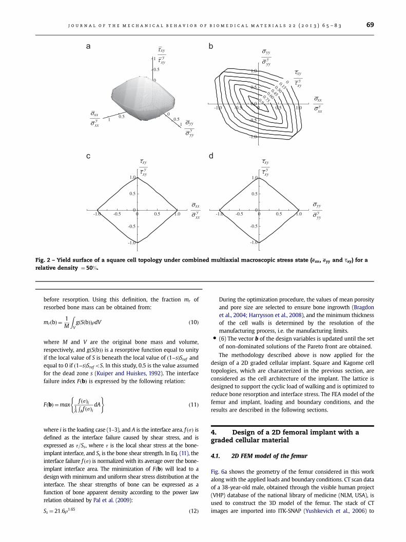
The yield surfaces of the cell topologies are also obtained formultiaxial macroscopic stresses. As shown in Eq. (6) and being inlinear elasticity, the location of the yield point on the yield surface ofeach lattice is obtained by multiplying the macroscopic stress withthe ratio of the material yield strength and the maximum von Misesstress. Figs. 2 and 3 show the yield surfaces normalized with respectto the yield strength of the square and Kagome lattices in the uniaxialand shear loading directions at a given relative density. Fig. 2 refers tothe square lattice for the relative density of 50%, and Fig. 3 pertains tothe Kagome cell for the relative density of 30%. We selected 30% forthe Kagome, because for a 50% relative density the base materialalmost completely fills the triangular voids, and thus the Kagomestructure cannot be realized.
Once the yield surface is determined, the multiaxial endurancelimit of the cell can be obtained by scaling the yield surface with thecoefficient given in Eq. (7). These data can be inserted intoEq. (8) for the infinite-life design of cellular structures under multi-axial fatigue loading conditions. For design purposes, it is oftenconvenient to resort to closed-form expressions that can approxi-mately describe the geometry of a yield surface. For this reason,Table 1 lists the functions along with relative fitting parameters of theyield surfaces for the unit cells here under investigation. For thesquare cell (Fig. 2b), a pyramid with an elliptical base is used toresemble the yield surface. Fn
xy (Table 1) governs both the slendernessratio and the inclination of the major axis of the elliptical base. For theKagome cell (Fig. 3b), the yield surface is approximated by aparallelogram, and m1 and m2 (Table 1) are the slopes of theparallelogram lines, expressed as a function of the relative density.The parameters syxx, s
yyy, τ
yxy (Table 1) are the yield strength of the unit
cell under uni-axial and shear stresses. Fig. 4a and b show thevariation of the yield strength as a function of relative density. Whenthe material is fully dense, the yield strength is equal to that of itssolid material. A common feature in the plots of Fig. 4 is the abruptdecrease of the effective yield strength for decreasing values ofrelative density. The reason for this is the presence of stressconcentration at the cell joints, which locally increases the level ofstress. We note here that the fatigue strength of the lattice can be
significantly improved by optimizing the cell shape and removing thecurvature discontinuity at the joints (Abad et al., 2012).
3. Fatigue design of a hip implant withcontrolled lattice microarchitecture
Fig. 5 illustrates the methodological steps to design a gradedcellular implant for infinite fatigue life. The approach combinesmultiscale mechanics and multiobjective optimization. Theformer deals with the scale-dependent material structure, wherethe local problem of the RVE is first solved, and then the effectiveelastic moduli and yield strength are obtained and used ashomogenized properties of the macroscopic model of the implant.The latter handles the conflicting nature of bone resorption andimplant interface stress. A fatigue failure theory can thus beembedded in the procedure to design the implant for infinitefatigue life. A brief description of the main steps identified by thenumbers in the flowchart is given in Fig. 5.
�
(1) A finite element model of the bone is created by processingCT-scan data of a patient bone.�
(2) A 3D lattice microstructure is considered as the buildingblock of the implant, and its mechanical properties arepredicted through AH. The homogenized elastic modulus,yield and fatigue surfaces of the cell topology under multiaxialloading conditions are obtained.�
(3, 4) From FEA, the mean and alternative macroscopic stressesare obtained, and used in the fatigue design diagram todetermine the design safety factor (SF). In this study, theSoderberg's fatigue failure criterion is considered for the analysis.�
(5) The two conflicting objective functions, bone resorptionmrðbÞ and interface failure index FðbÞ, are minimized via amultiobjective optimization strategy subjected to a set ofinequality constraints. The amount of bone resorption isdetermined by comparing the local strain energy per unit ofbone mass between the preoperative and the postoperativesituation. Bone start to lose mass when its local strain energy(Ui) per unit of bone mass (ρ), averaged over n loading cases(S¼ ðð1=nÞΣni ¼ 1Ui=ρÞ), is beneath the local reference valueð1−sÞSref . Sref is the value of S when no prosthesis is present,and s is the threshold level or dead zone that bone can tolerate
-1-0.5
00.5
1
-1-0.5
00.5
1
-1
-0.5
0
0.5
1
-1.0 -0.5 0 0.5 1.0
-1.0
-0.5
0.0
0.5
1.0
00.150.300.450.600.750.9
-1.0 -0.5 0 0.5 1.0
-1.0
-0.5
0
0.5
1.0
-1.0 -0.5 0 0.5 1.0
-1.0
-0.5
0
0.5
1.0
yxx
xxσσ
yyy
yyσ
σ
yxyτ
yxx
xxσσ
yyy
yyσ
σ
yxy
xyτ
τ
yxx
xxσσ y
yy
yyσ
σ
xyτy
xyτxyτy
xyτ
τxy
Fig. 2 – Yield surface of a square cell topology under combined multiaxial macroscopic stress state (rxx, ryy and τxy) for a
relative density ¼ 50%.
j o u r n a l o f t h e m e c h a n i c a l b e h a v i o r o f b i o m e d i c a l m a t e r i a l s 2 2 ( 2 0 1 3 ) 6 5 – 8 3 69
before resorption. Using this definition, the fraction mr ofresorbed bone mass can be obtained from:
mrðbÞ ¼1M
ZVgðSðbÞÞρdV ð10Þ
where M and V are the original bone mass and volume,respectively, and gðSðbÞÞ is a resorptive function equal to unityif the local value of S is beneath the local value of ð1−sÞSref andequal to 0 if ð1−sÞSrefoS. In this study, 0.5 is the value assumedfor the dead zone s (Kuiper and Huiskes, 1992). The interfacefailure index FðbÞ is expressed by the following relation:
FðbÞ ¼maxf ðsÞi
1A
RAf ðsÞi
dA
( )ð11Þ
where i is the loading case (1–3), and A is the interface area. f ðsÞ isdefined as the interface failure caused by shear stress, and isexpressed as τ=Ss, where τ is the local shear stress at the bone-implant interface, and Ss is the bone shear strength. In Eq. (11), theinterface failure f ðsÞ is normalized with its average over the bone-implant interface area. The minimization of FðbÞ will lead to adesignwith minimum and uniform shear stress distribution at theinterface. The shear strengths of bone can be expressed as afunction of bone apparent density according to the power lawrelation obtained by Pal et al. (2009):
Ss ¼ 21:6ρ1:65 ð12Þ
During the optimization procedure, the values of mean porosityand pore size are selected to ensure bone ingrowth (Bragdonet al., 2004; Harrysson et al., 2008), and the minimum thicknessof the cell walls is determined by the resolution of themanufacturing process, i.e. the manufacturing limits.
�
(6) The vector b of the design variables is updated until the setof non-dominated solutions of the Pareto front are obtained.The methodology described above is now applied for thedesign of a 2D graded cellular implant. Square and Kagome cell
topologies, which are characterized in the previous section, areconsidered as the cell architecture of the implant. The lattice isdesigned to support the cyclic load of walking and is optimized toreduce bone resorption and interface stress. The FEA model of thefemur and implant, loading and boundary conditions, and theresults are described in the following sections.4. Design of a 2D femoral implant with agraded cellular material
4.1. 2D FEM model of the femur
Fig. 6a shows the geometry of the femur considered in this workalong with the applied loads and boundary conditions. CT scan dataof a 38-year-old male, obtained through the visible human project(VHP) database of the national library of medicine (NLM, USA), isused to construct the 3D model of the femur. The stack of CTimages are imported into ITK-SNAP (Yushkevich et al., 2006) to

Fig. 3 – Yield surface of a Kagome cell topology under combined multiaxial macroscopic stress state (rxx, ryy and τxy) for a
relative density ¼ 30%.
Table 1 – Yield surfaces as a function of relative density for square and Kagome unit cells.
Yield function Constant
sxxsyxx
� �2
þ 2Fn
xysxxsyxx
� �syysyyy
!þ syy
syyy
!2
¼ τxyτyxy
−1
!2 Fn
xy ¼−1:6787ρ2 þ 2:539ρ−0:42
max
sxxsyxx
� syym1s
yyy
��� ���� 1� txytyxy
��������a� �
,
syysyyy
�m2sxxsyxx
��� ���� 1� txytyxy
��������b
!8>>>><>>>>:
9>>>>=>>>>;
¼ 0
forρo0:6 a¼ 16:52ρ2−23:1ρþ 9:2750:6oρo1 a¼ 1:5
(
forρo0:6 b¼−11:61ρ2 þ 10:125ρþ 1:050:6oρo1 b¼ 3
(
forρo0:6 m1 ¼ 1:15e6:9ρ
0:6oρo1 m1 ¼−205:88ρ2 þ 164:83ρþ 46:97
(
forρo0:6 m2 ¼ 0:305ρ2:35
0:6oρo1 m2 ¼ 0:3783ρ2:811
(
j o u r n a l o f t h e m e c h a n i c a l b e h a v i o r o f b i o m e d i c a l m a t e r i a l s 2 2 ( 2 0 1 3 ) 6 5 – 8 370
create the STL file of the femur geometry by using the semi-automated segmentation process. The 3D geometry is then createdby using SolidWorks® software package, and meshed with tetra-hedron elements in ANSYS (Canonsburg, Pennsylvania, U.S.A). Theapparent density ρ for each element of the FE model is thendetermined from the Hounsfield value (HU) measured from CTdata ranging from −1024 HU to 1567 HU. The CT data set
represents a regular cubic grid where a HU value is assigned ateach point. A linear relation between HU and apparent density isconsidered. The maximum value of HU corresponds to the densestregion of the cortical bone with apparent density of 2.0 g/cm3, andHU value of water and its apparent density equal to zero. Once theapparent density of each CT grid point is obtained, elements of theFE model are superimposed on the CT grid points to evaluate the

Fig. 4 – Yield strength as a function of relative density for (a) square and (b) Kagome.
Fig. 5 – Flow chart illustrating the fatigue design methodology of a graded cellular hip implant.
j o u r n a l o f t h e m e c h a n i c a l b e h a v i o r o f b i o m e d i c a l m a t e r i a l s 2 2 ( 2 0 1 3 ) 6 5 – 8 3 71
average of relative density for each element using the proceduredescribed in Zannoni et al. (1999). From the apparent densitydistribution, the effective elastic moduli of bone are obtainedthrough the relation (Austman et al., 2008; Baca et al., 2008;Peng et al., 2006):
E¼ 1904ρ1:64 ρo0:95E¼ 2065ρ3:09 0:95oρ
, ν¼ 0:3
(ð13Þ
An isotropic material model is considered for the bone, as thissimplification does not lead to a noticeable difference from thoseresults obtained by assigning to the bone orthotropic materialproperties (Baca et al., 2008; Peng et al., 2006).
For the purpose of this exploratory study, the 3D geometry of thefemur is simplified to a 2D model, which is assumed to have a sideplate of variable thickness (Huiskes, 1990; Weinans et al., 1994). Themid-frontal section of the femur is considered for the 2D modelgeometry, and the anterior and posterior parts of the femur arerepresented by the side plate. The 2D model and the side plate havevariable thickness such that the second moment of area about theout-of-plane axis of the 2D model does not differ from that of the 3Dmodel (Huiskes et al., 1987; Weinans et al., 1992a, b). The material
properties of the front plate are extracted from the mid-frontalsection of the 3D model, and the mechanical properties of the corticalbone are considered for the side plate. This simplification helpsreduce the computational cost involved in the optimization process.Nevertheless, many of the essential features of the implant physicscan still be captured with a 2D model. For mid-frontal loadings, vonMises and interface stresses distribution can be calculated with anaccuracy similar to that of a full 3D model (Weinans et al., 1994). As aresult, the remodeling process in the metaphyseal and diaphysealparts, and the failure at the bone-implant interface, can be approxi-mated with a 2D geometry. The distal end of the femur is fixed toavoid rigid body motion, and three loading cases, 1–3, representingthe cyclic load during walking movements are applied to the hip jointand the abductor (Carter et al., 1989; Pérez et al., 2010; Weinans et al.,1992a). With respect to the load cases, magnitude and direction of thehip joint are given here together with the abductor forces in brackets:(1) 2317 N at 241 from vertical (702 N at 281 from vertical), (2) 1158 Nat 151 from vertical (351 N at 81 from vertical), (3) 1548 N at 561 fromvertical (468 N at 351 from vertical). ANSYS (Canonsburg, Pennsylva-nia, USA) is used to build, mesh, and solve the 2D model. Assumingin-plane loading conditions, a 2D eight-node element type (Plane 82)is used since it can model curved boundaries with high accuracy.

Fig. 6 – (a) 2D Finite element models of the femur and (b) the prosthesis implanted into the femur.
j o u r n a l o f t h e m e c h a n i c a l b e h a v i o r o f b i o m e d i c a l m a t e r i a l s 2 2 ( 2 0 1 3 ) 6 5 – 8 372
4.2. FEM model of the cellular implant
Fig. 6b illustrates the model of a cementless prosthesisimplanted into the femur. The grid depicts the domain of theimplant to be designed with a functionally graded latticematerial. The variable of the lattice model is the relative densityattributed to 115 sampling points, 23 rows along the prostheticlength and 5 columns along the radial direction. The values ofrelative density are constrained in the range 0:1≤ρ≤1 to preventelastic buckling in the unit cell from occurring prior to yielding(Wang and McDowell, 2004). The relative density distributionthroughout the implant is obtained by linear interpolationbetween the corresponding values at the sampling points. Thehomogenized stiffness matrix and the yield surfaces of eachelement are then computed from those values, respectively,illustrated in Fig. 1 and Table 1. The former is employed toassemble the global stiffness matrix for the Finite Element (FE)solver, and the latter is used to construct the Soderbergdiagram for fatigue analysis.
Since the implant is designed to have a cellular microstructurewith suitable pore size for bone ingrowth, it is assumed that theprosthesis and the surrounding bone are fully bonded (Khanokiand Pasini, 2012; Kowalczyk, 2001). This choice significantlydecreases the computational cost required for the stability
analysis based on a non-linear frictional contact model(Viceconti et al., 2000). Although bone ingrowth does not existin a postoperative situation, it can appear later, if local mechanicalstability is guaranteed. It is expected, however, that the mini-mization of interface stress reduces the risk of interface micro-motion and instability (Kowalczyk, 2001).
5. Results
The procedure illustrated in Section 3 is applied for the fatiguedesign of the implant after having calculated the yield and fatiguestrengths of the microstructure, as described in section 2. To solvethe multiobjective optimization problem, the non-dominatedsorting genetic (NSGA-II) algorithm (Deb et al., 2002) is hereused. Once the initial population is evaluated, a set of solutions,called parents, are selected based on their rank and crowdingdistance. Genetic operators are then applied to the population ofparents to create a population of off-springs. Finally, the nextpopulation is produced by taking the best solutions from thecombined population of parents and off-springs. The optimizationcontinues until the user-defined number of function evaluationsreaches 25,000 (Deb et al., 2002). The computational costrequired to run the optimization process in a single 2.4 GHz Intel

Fig. 7 – Trade-off distributions of relative density for the optimized cellular implant made of (a) square and (b) Kagome
lattices.
j o u r n a l o f t h e m e c h a n i c a l b e h a v i o r o f b i o m e d i c a l m a t e r i a l s 2 2 ( 2 0 1 3 ) 6 5 – 8 3 73
processor was about 300,000 CPU seconds, 3 days and a half.Parallel computing with a PC cluster will considerably reduce thecomputational time, since each function evaluation can beperformed independently.
Fig. 7(a) and (b) show the optimum relative density distribu-tions for a 2D hip stem designed with square and Kagome celltopologies. The x axis represents the amount of bone resorptionfor the implanted hip; on the y axis is the interface failure index.Among the optimal solutions, we examine three representativerelative density distributions: the extreme points, A and C, of thePareto frontier, for which one objective function has importancefactor 0 and the other 100%, and solution B characterized byweight factors of 50%. For these solutions, the following char-acteristics are also illustrated in Fig. 7: amount of bone resorption(mr), interface failure index (FðbÞ), maximum shear interface
failure (f ðsÞmax), average porosity of each hip stem (ϕ), and designfatigue safety factor (SF) from the Soderberg diagram.
The advantage of formulating and solving the problem as amultiobjective optimization task is that a set of optimum solu-tions are available to the user, without requiring to choose inadvance any weighting factors for the objective functions. Oncethe whole set of Pareto solutions has been determined, thesurgeon has the freedom to select the desired implant designbased on the relative importance of the objective functions.Through a comparison of the results, we observe that an increasein implant porosity from point C to A results in a stiffnessdecrease of the implant. This increase, on one hand, lowers boneloss, and, on the other, enhances the risk of interface failure.The implant initial stability is the first objective in hip replace-ment surgery as it governs the long term performance and the

j o u r n a l o f t h e m e c h a n i c a l b e h a v i o r o f b i o m e d i c a l m a t e r i a l s 2 2 ( 2 0 1 3 ) 6 5 – 8 374
success rate of the implant. Therefore, the implant with max-imum stability, solutions C in Fig. 7a and b, might be selectedfrom the Pareto front. By contrasting solutions B and C, we note asignificant reduction of bone resorption with only a slightincrease of the interface failure index. From solution C to B(Fig. 7a and b), the amount of bone resorption decreases by 62%and 51%, respectively, and the interface failure index increases by17% and 15%. Solutions B can thus be considered as preferreddesigns. It should be noted, however, that the selection of the best
Reladi
Reld
von Mises stressdistribution
0 0.1 0.4 0.0.30.2
0.05 5 10 20 3
von Mises stressdistribution
Fig. 8 – Regions used to verify the results of the AH model (left
lattice microstructure (right).
implant depends also on other factors, such as patient's bonecharacteristics, the range of activity, age, and the desired level ofbone mass preservation after implantation.
As can also be seen compared to the implant with squarelattice, the implants designed with Kagome cells have betterperformance in terms of bone loss and interface shear stress.If solutions B in Fig. 7a and b are compared, we note that theamount of bone loss decreases of about 4.2% and the shear stressconcentration factor at the interface reduces by up to about 24.5%.
tive densitystribution
ative densityistribution
Microstructure
Microstructure
Relative density5 0.6 0.7 0.8 0.9 1
0 40 50 60 70 MPa
and middle) with respect to a detailed FE analysis of a 5�5

j o u r n a l o f t h e m e c h a n i c a l b e h a v i o r o f b i o m e d i c a l m a t e r i a l s 2 2 ( 2 0 1 3 ) 6 5 – 8 3 75
While both implants have been designed for infinite fatigue life,the fatigue safety factor has improved approximately 81% for theimplant designed by the graded Kagome cell topology. The reasonfor this is that Kagome is a stretching dominated cell with highermechanical strength compared to the square cell for a givenrelative density. This provides a wider range of relative density forthe optimization search to choose the design variable from, andcontrol the stress distribution at the interface. Moreover, lowervalues of relative density can be selected to increase the implantflexibility and reduce bone resorption. We remark here thatbeside mechanical strength, other physical parameters, such aspore shape, interconnectivity, permeability and diffusivity of theunit cell, should be taken into account for the selection of aproper lattice cell for bone tissue scaffolding (Hollister, 2005;Hollister et al., 2008; Kang et al., 2010; Reilly and Engler, 2010;Van Bael et al., 2012). Further research is required in the nearfuture to address these aspects.
6. Verification of the numerical results
During the optimization procedure, AH is applied for the multi-scale analysis of the cellular implants. Although this method isquite effective in computing the stress and strain distribution ateach scale, the results needs to be verified especially at regionswhere the underlying assumption, Y-periodicity of field quanti-ties, is not satisfied. This can include regions with locally varyingstructure, areas with a high gradient of field quantities, or zonesin the vicinity of borders (Dumontet, 1986; Ghosh et al., 2001;Lefik and Schrefler, 1996; Raghavan and Ghosh, 2004; Takanoet al., 2003; Yuan and Pagano, 2003). The multilevel computa-tional method can be used for the analysis of these critical regions(Ghosh et al., 2001; Raghavan and Ghosh, 2004). This methoddecomposes the computational domain into two levels of hier-archy: (a) the detailed cellular microstructure and (b) the homo-genized medium. The region of interest, composed of a cellularmicrostructure, is modeled by a fully detailed FE analysis, and theresults are compared with those obtained from the homogeniza-tion method to verify the periodicity assumption of AH.The following criterion can be defined to measure the departurefrom the periodicity conditions:
L=2mm
x
y
L6.0
L6.0
Fig. 9 – (a) 3�3 Gauss points in the RVE; (b) superposition of the
Fðsij,εijÞFEA−Fðsij,εijÞRVEFðsij,εijÞRVE
≥C ð14Þ
where the function F is a function of (sij,εij) and can be defined, forexample, as the average of the microscopic stress over the RVE.The superscript FEA refers to the evaluation of the function F via adetailed finite element analysis of a given microstructure. Themacroscopic displacement solution, obtained from the homoge-nized model, is imposed on the unit cell boundary of the detailedFE model, and the stress and strain distribution within themicrostructure is obtained. The superscript RVE, on the other hand,corresponds to the computation of F for each RVE through theimposition to the unit cell of a macroscopic strain with periodicboundary conditions. C is a user defined adaptation tolerance;C¼0.1 can be considered as an appropriate transition value to mapthe homogenized model to the detailed analysis of the localmicrostructure (Raghavan and Ghosh, 2004). Here as functions,(a) the average and (b) the maximum value of von Mises stressover the unit cell, are considered, respectively, to verify theperiodicity assumption of field quantities at the macroscale, andto assess the estimation of material yield in the lattice.
We investigate two regions to verify the results of AH: one at theproximal part, where the Y-periodic assumption of field quantities isexpected, and the other at the vicinity of the implant boundary,where this assumption does not hold. Fig. 8 illustrates the macro-scopic von Mises stress distribution throughout the square andKagome lattice implants associated with the loading conditionnumber 1 applied to the hip joint. The mesh of the macroscopicelements at the vicinity of the implant border has been refined tocapture the interface stresses with a higher resolution. The stressand relative density distribution, shown in Fig. 8, corresponds to thesolutions B in Fig. 7. We can observe almost a uniform stressdistribution in the proximal region of the implants; however, thereis higher stress gradient at the vicinity of the implant boundaryespecially for the square lattice implant, which might affect theperiodicity assumption of AH. To perform the detailed FEA andverify the results of AH, the microstructures need to be constructedat the specified regions. For the square cell, a 2 mm�2 mm size isselected to satisfy the manufacturing constraint (tmin≥0:1 mm forρ≥0:1) and to uniformly tessellate the regions with a 5�5 cellsblock. For the Kagome topology, the RVE has a rectangular shapewith the same cell size as the square in the x direction. To produce
Macroscopic element
Gauss point
RVE on the macroscopic mesh of the homogenized model.

j o u r n a l o f t h e m e c h a n i c a l b e h a v i o r o f b i o m e d i c a l m a t e r i a l s 2 2 ( 2 0 1 3 ) 6 5 – 8 376
the cell geometry from the relative density distribution, 3� 3 Gausspoints are assigned to each cell, as shown in Fig. 9. Using a Gaussianquadrature integration (Zienkiewicz and Taylor, 2005), the averagerelative density of the RVE is obtained as:
ρ¼ ∑9
i ¼ 1∑9
j ¼ 1Wijρij ð15Þ
where ρij and Wij are the relative density and weight factors at eachGauss point, respectively. The relative density at each Gauss point isobtained with respect to its local coordinates within the macro-scopic element of the homogenized model (Fig. 9). Once the averagerelative density is obtained, the cell geometry can be constructed forboth the square and Kagome lattices, as depicted in Fig. 8. Thedisplacement of the macroscopic solution is then imposed on theboundary of the cells block (Raghavan and Ghosh, 2004), so as tocalculate the stress distribution of the microstructure. The averageand the maximum von Mises stress for the unit cells is then
xx
-0.249-0.296
-0.203
-0.111-0.064-0.018-0.028-0.074
-0.157
×10-3
xx
-0.035-0.063
-0.008
0.0480.0750.1030.1310.159
0.020
×10-3
xx
-0.264-0.356
-0.173
0.0090.0960.1920.2830.374
-0.086
×10-3
xx
-0.152-0.235
-0.068
0.0970.1800.2630.3460.429
0.014
×10-3
Fig. 10 – Macroscopic strain distribution (solution B in Fig. 7a a
and (b) the border of the square lattice implant, and (c) the prox
computed and used in Eq. (14) to verify the periodicity assumptionand the results of AH.
To recover the stress distribution throughout the microstructurevia AH, the average macroscopic strain is needed over the RVE.Fig. 10 illustrates the macroscopic strains distribution, εxx, εyy, τxy,over the regions proximal and closed to the boundary of the squareand Kagome lattice implants. As can be seen, there is a uniformvariation of macroscopic strains in the proximal region, while thereis high strain gradient close to the boundary which might affect theAH periodicity assumption. Therefore, the results obtained by thehomogenization method needs to be verified. Using the proceduredescribed above, the average macroscopic strain for each unit cell iscomputed; the strain tensor is used in Eq. (2) to obtain themicroscopic strain distribution throughout the microstructure, fromwhich the microscopic stresses are calculated via the constitutiveequation of the base material. For the block at the proximal region,the microscopic stress distribution of the unit cell located at thecenter of the block is compared with those obtained from a detailed
yy xy
-0.379-0.206
0.1400.3120.4850.6580.830
-0.332
-0.551×10⁻³
-2.421-1.781
-0.5010.1400.7801.4222.064
-1.141
-3.061×10⁻³
yy xy
-0.811-0.627
-0.259-0.0740.1100.2940.478
-0.443
-0.995×10⁻³
-0.4490.347
0.9521.2541.5571.8592.162
0.650
-0.258×10⁻³
yy xy
-0.780-0.517
0.0100.2730.5360.8021.063
-0.253
-1.043×10⁻³
-0.482-0.298
0.0680.2520.4360.6200.804
-0.536
-0.666×10⁻³
yy xy
-1.006-0.738
-0.2030.0650.3330.6000.868
-0.470
-1.273×10⁻³
-0.0780.060
0.3360.4740.6130.7510.889
0.198
-0.216
×10-3
nd Fig. 7b) as a result of load case 1 at (a) the proximal part
imal part and (d) the border of the Kagome lattice implant.

Table 2 – Comparison of microscopic stress distribution obtained by detailed FEA and AH for the unit cells located at theproximal region and closed to the implant border.
Proximal cell Boundary cell Proximal cell Boundary cell
AH
FEA
Error (svM )a 0.98% 1.8% 1.2% 3.8%
Error (maxfsvMg)b 7.1% 8.7% 8.2% 18.6%
a The error corresponds to the average of von Mises stress over the unit cell.b The error corresponds to the maximum von Mises stress over the unit cell.
j o u r n a l o f t h e m e c h a n i c a l b e h a v i o r o f b i o m e d i c a l m a t e r i a l s 2 2 ( 2 0 1 3 ) 6 5 – 8 3 77
FEA. For the block at the implant border, the stress distributionwithin the cell in the middle of the first column of Fig. 8 isconsidered. Based on the results of several analyses, we haveobserved that a change of the block position has a negligible effecton the unit cell stress distribution if the location of the selected unitcell is prescribed within the implant.
The von Mises stress distribution of the unit cells, obtained byAH and by detailed FE analysis, are given in Table 2. The averageand the maximum value of von Mises stress over the unit cellsobtained by AH are also compared with the detailed FE analysis,and the relative errors, defined by Eq. (14), are illustrated inTable 2. For the square unit cell located in the proximal region,the average and the maximum value of von Mises stress can beestimated with an error of 0.98% and 7.1%, respectively. However,for the unit cells close to the boundary, a higher relative error forthe microscopic stresses is observed as the Y-periodic assumptionis not satisfied. For the Kagome lattice located in the proximalregion, the relative error for the average and the maximum vonMises stress is 1.2% and 8.2%, respectively, percentages thatincrease to 3.8 and 18.6 when the Kagome unit cell is located atthe implant boundary. Considering C¼0.1 as the criterion forcreating the transition from the homogenized model to the fullydetail analysis, it can be seen that the periodicity assumption cancapture the average of the macroscopic stress distribution through-out the implant with an error below 0.1. The average macroscopicstress in Table 1 can be used to assess the material yield at themicroscopic level of the lattice struts. For unit cells located at the
implant boundary, where non-periodic local heterogeneity andnon-uniform macroscopic field exist, the finite element meshsuperposition method integrated with AH is better suited tocapture the microscopic stress distribution with higher accuracy(Takano et al., 2010, 2000, 2003; Takano and Okuno, 2004). Thiswould significantly reduce the computational cost of the numericalsimulations, since a fully detailed FEA of the implant might beunfeasible. The computational cost required to perform a singlesimulation of a fully detailed FE model of a cellular implant on a2.4 GHz Intel processor is about 1500 CPU seconds. Considering25,000 function evaluations for the optimization procedure, thesimulation time required for the fully detailed FE model would be3.75�107 s which is about 100 times higher than the simulationtime needed for the analysis of a homogenized model.
7. Discussions
In this section, we examine the results within the context of aperformance comparison of other implants currently available inthe market as well as on the manufacturability aspects. As abenchmark for the comparative study, a fully dense titaniumimplant is chosen. Its bone resorption and the distribution of localshear interface failure are determined, and then compared withthose of the cellular implants represented by solutions B in Fig. 7for both the square and Kagome lattice.

Resorbed bone Non resorbed bone Implant
Fig. 11 – Distribution of bone resorption around (a) fully dense titanium implant, (b) graded cellular implant with square
topology (solution B in Fig. 7a), (c) graded cellular implant with Kagome topology (solution B in Fig. 7b).
j o u r n a l o f t h e m e c h a n i c a l b e h a v i o r o f b i o m e d i c a l m a t e r i a l s 2 2 ( 2 0 1 3 ) 6 5 – 8 378
As expected, Fig. 11a shows that for a fully dense implant, bonemass loss is about 71.4%. This initial postoperative configuration ofbone loss is in good agreement with that in literature (Huiskeset al., 1992; Weinans et al., 1992a). A high amount of boneresorption is found throughout the medial and lateral part ofthe femur around the fully dense stem. Compared to the fullydense implant, the amount of initial postoperative bone loss ofthe square and Kagome lattice implants decreases, respectively,by 53.8% and 58%. This shows that the design of a flexible implantthrough a graded cellular material has the beneficial effect ofimproving the load-sharing capacity of the implant with thesurrounding bone, thereby reducing bone resorption.
Fig. 12 shows the distribution of the local shear interfacefailure, f ðsÞ, around the fully dense titanium, square and Kagomelattice implants. At each point, the maximum value of interfacefailure caused by any of three loading cases is shown. Since thefunction f ðsÞ is the interface shear stress normalized with respectto the local shear strength of the bone, high probability ofinterface failure is expected for f ðsÞ≥1, whereas for f ðsÞo1 therisk of interface failure is low. For the fully dense titaniumimplant, we observe that the maximum value of shear interfacefailure occurs at the distal end with magnitude of 0.96.This means that the shear stress is almost equal to the shearstrength of the host bone, which may cause interface micromo-tion and prevent bone ingrowth. For the square and Kagomelattice implants, the maximum shear interface failure reducessignificantly of about 79% to 0.19 and 0.2, respectively. Anoptimized graded distribution of the cellular microarchitecturecan reduce the stress distribution at the implant interface. For thenumerical verification, the interface shear stress of fully densetitanium implant is also compared with those obtained inliterature (Kuiper and Huiskes, 1992, 1996). We have that the
interface shear stress varies from 3.8 MPa at the proximal regionto the maximum value of 42 MPa at the distal end, which is ingood agreement with the stress regime available in (Kuiper andHuiskes, 1992, 1996).
The fatigue analysis of the fully dense titanium implant showsthat its safety factor is 4.95. Although this value is about twotimes higher than the corresponding value of the Kagome latticeimplant, a safety factor of 2.3 for Kagome lattice implant can bestill considered as a reasonably safe margin for the design againstfatigue fracture. To improve the implant fatigue strength, either alattice with smooth cell geometry could be considered (Abadet al., 2012), or the implant core can be designed as fully dense.
To assess the manufacturability of the implant microarchitec-ture, 2D proof-of-concepts implants were fabricated via EBM.Ti6Al4V powder supplied by ARCAM (2013) with powder particlesize between 45 μm and 100 μm was used for fabrication.The relative density distribution of solution C in Fig. 7a wasselected and mapped into a square lattice implant with thefollowing cell size: 1 mm, 2 mm, and 3 mm. A uniform celltessellation was assumed to draw the geometric model. 3� 3Gauss points were assigned to each cell, and the average ofrelative density was computed through Eq. (15). The geometry ofeach lattice cell was then calculated from the average relativedensity and the size of the unit cell. STL files of the cellularimplants were created and finally processed by EBM.
Fig. 13 shows the implants with their representative micro-structure. An optical microscope equipped with a digital camerawas used to measure morphological parameters of the cell, suchas cell wall thickness and pore size. No sign of fracture orincomplete cell walls was inspected, an observation that showsgood metallurgic bond between cell walls and structural integrityof the lattice. Fig. 14 provides the comparison of the average cell

0.5
Fig. 12 – Distribution of local shear interface failure fðrÞ around (a) fully dense titanium implant, (b) graded cellular implant
with square topology (solution B in Fig. 7a), (c) graded cellular implant with Kagome topology (solution B in Fig. 7b).
Fig. 13 – Fabricated Ti6Al4V graded cellular implants with their corresponding microstructure.
j o u r n a l o f t h e m e c h a n i c a l b e h a v i o r o f b i o m e d i c a l m a t e r i a l s 2 2 ( 2 0 1 3 ) 6 5 – 8 3 79
wall thickness and pore size between the nominal values and thefabricated parameters for each prototype.
For the implant with unit cell size of 1mm, the average wallthickness and pore size exhibit a high relative error. The average wall
thickness of the fabricated implant is 33.5% higher than the nominalvalue, while its average pore size is 53.6% lower than the nominal one.As can be seen in Fig. 13, the pores are partially filled with non-fullymelted powder particles, a side-effect that increases the wall

1 2 30
0.5
1.0
1.5
2.0
Δ = 1.5%
Δ = 33.5%
DesignedFabricated
Cell size (mm)
Cel
l wal
l thi
ckne
ss (m
m)
1 2 30
0.5
1.0
1.5
2.0
2.5Δ = 0.1%
Δ = 5.5%
Cell size (mm)
Cel
l por
e si
ze (m
m)
DesignedFabricated
Δ = 53.6%
Δ = 0.2%
Δ Δ
Fig. 14 – Cell wall thickness and pore size of cellular implants fabricated with alternative cell size are compared to the
nominal design parameters. Δ represents the difference between the average as-fabricated and the nominal values.
j o u r n a l o f t h e m e c h a n i c a l b e h a v i o r o f b i o m e d i c a l m a t e r i a l s 2 2 ( 2 0 1 3 ) 6 5 – 8 380
thickness and decreases the effective pore size. Although the poressize range between 60 μm and 560 μm is still an optimum range forbone ingrowth, the average pore size has decreased of 46%, from thenominal value of 660 μm to the real size of 306 μm.
On the other hand, for cell size of 2 mm and 3 mm, themorphological parameters are in a good agreement with thedesign values. The difference between the average pore sizedecreases from 5.5% for 2 mm unit cell size to a negligible valueof 0.1% for 3 mm cell size. While a cell size increase provides morecontrol on the results, it may lead to a pore size greater than thesuitable size for bone ingrowth. For the prototype with unit cellsize of 2 mm, the pore size varies between 323 μm and 1305 μmwith an average of 1040 μm; this value is slightly higher than theoptimum size for bone ingrowth. For the implant with unit cellsize of 3 mm, the pore size range is between 395 μm and 2240 μmwith an average of 1660 μm, which is significantly higher than theoptimum size prescribed for bone ingrowth. To provide a suitableenvironment for bone ingrowth, a periphery layer with either asmaller unit cell size or a conventional porous coating is sug-gested to be integrated on the implant surface.
Exploratory in nature, this study holds some limitations, which arehere discussed. For the numerical simulation, the material has beenassumed free of defects with mechanical properties comparable tothose of the bulk material. The effect of unevenness of samplessurface leading to surface curvatures and corrugation could be alsoaccounted for. These defects result in local non-periodic heterogene-ities and stress concentrations which affect the stiffness and strengthof the lattice. A multiscale finite element analysis (Takano et al., 2010,2003; Takano and Okuno, 2004) combining enhanced mesh super-position method with AH theory could be implemented. In addition,further work is required to examine the sensitivity of the results tovariations of bulk material properties. Another aspect is the simpli-fication of the 3D model of the implanted femur to a 2D model. Toextend the proposed procedure to three dimensions, the 3D geometryof the implanted femur should be created. Then the topology of thethree-dimensional lattice at the periphery of the implant should beselected to respect desired values of porosity and cell
interconnectivity (Cheah et al., 2003a, b) to meet bone vascularizationrequirements. Finally, more detailed models on bone resorption(Boyle and Kim, 2011a, b; Weinans et al., 1992a, b) and implantstability (Abdul-Kadir et al., 2008; Viceconti et al., 2006, 2001, 2000)could be used to assess both the short and long term performance ofthe implant.
8. Conclusions
A hip-joint implant with a graded lattice material can improve theload sharing capacity of the implant with the surrounding bonetissues as well as decrease the amount of bone resorption. In thisstudy, the lattice microarchitecture of a 2D proof-of-conceptimplant has been designed against fatigue fracture to supportcyclic loads in the hip joint. Asymptotic homogenization has beenused for the multiscale analysis of the structure to obtain thestress distribution at the macro and micro scale, while theSoderberg fatigue criterion has been integrated in the procedureto design the implant for infinite fatigue life. The numericalresults obtained have been verified via a detailed FE analysis.Square and Kagome lattices have been used in a multiobjectiveoptimization procedure to simultaneously minimize bone resorp-tion and interface failure. It has been found that for the squareand Kagome lattice implants the amount of bone loss is respec-tively 54% and 58% lower than that of a fully dense titaniumimplant. The maximum shear interface failure at the distal end ofthe implants decreases as well of about 79%. Finally, a set of 2Dproof-of-concepts have been fabricated with EBM to demonstratethe manufacturability of the lattice implants.
r e f e r e n c e s
Abad, E.M.K., Khanoki, S.A., Pasini, D., 2012. Fatigue design of latticematerials via computational mechanics: application to lattices

j o u r n a l o f t h e m e c h a n i c a l b e h a v i o r o f b i o m e d i c a l m a t e r i a l s 2 2 ( 2 0 1 3 ) 6 5 – 8 3 81
with smooth transitions in cell geometry. International Journal ofFatigue.
Abdul-Kadir, M.R., Hansen, U., Klabunde, R., Lucas, D., Amis, A., 2008.Finite element modelling of primary hip stem stability: the effectof interference fit. Journal of Biomechanics 41, 587–594.
ARCAM, 2013. Ti6Al4V Titanium Alloy.Austman, R.L., Milner, J.S., Holdsworth, D.W., Dunning, C.E., 2008. The
effect of the density–modulus relationship selected to applymaterial properties in a finite element model of long bone. Journalof Biomechanics 41, 3171–3176.
Baca, V., Horak, Z., Mikulenka, P., Dzupa, V., 2008. Comparison of aninhomogeneous orthotropic and isotropic material models usedfor FE analyses. Medical Engineering & Physics 30, 924–930.
Baleani, M., Cristofolini, L., Viceconti, M., 1999. Endurance testing ofhip prostheses: a comparison between the load fixed in ISO 7206standard and the physiological loads. Clinical Biomechanics 14,339–345.
Behrens, B., Wirth, C., Windhagen, H., Nolte, I., Meyer-Lindenberg, A.,Bouguecha, A., 2008. Numerical investigations of stress shieldingin total hip prostheses. Proceedings of the Institution ofMechanical Engineers Part H: Journal of Engineering in Medicine222, 593–600.
Bendsøe, M.P., Kikuchi, N., 1988. Generating optimal topologies instructural design using a homogenization method. ComputerMethods in Applied Mechanics and Engineering 71, 197–224.
Bendsøe, M.P., Sigmund, O., 2003. Topology Optimization: Theory,Methods, and Applications. Springer Verlag, Berlin, Heidelberd,New York.
Bobyn, J.D., Poggie, R., Krygier, J., Lewallen, D., Hanssen, A., Lewis, R.,Unger, A., O'keefe, T., Christie, M., Nasser, S., 2004. Clinicalvalidation of a structural porous tantalum biomaterial for adultreconstruction. The Journal of Bone and Joint Surgery 86, 123–129.
Boyle, C., Kim, I.Y., 2011a. Comparison of different hip prosthesisshapes considering micro-level bone remodeling and stress-shielding criteria using three-dimensional design space topologyoptimization. Journal of Biomechanics 44, 1722–1728.
Boyle, C., Kim, I.Y., 2011b. Three-dimensional micro-levelcomputational study of Wolff's law via trabecular bone remodelingin the human proximal femur using design space topologyoptimization. Journal of Biomechanics 44, 935–942.
Bragdon, C., Jasty, M., Greene, M., Rubash, H., Harris, W., 2004. Biologicfixation of total hip implants: insights gained from a series ofcanine studies. The Journal of Bone and Joint Surgery 86, 105–117.
Carter, D., Orr, T., Fyhrie, D., 1989. Relationships between loadinghistory and femoral cancellous bone architecture. Journal ofBiomechanics 22, 231–244.
Cheah, C., Chua, C., Leong, K., Chua, S., 2003a. Development of a tissueengineering scaffold structure library for rapid prototyping. Part 1:Investigation and classification. The International Journal ofAdvanced Manufacturing Technology 21, 291–301.
Cheah, C., Chua, C., Leong, K., Chua, S., 2003b. Development of a tissueengineering scaffold structure library for rapid prototyping. Part 2:Parametric library and assembly program. The InternationalJournal of Advanced Manufacturing Technology 21, 302–312.
Coelho, P., Fernandes, P., Guedes, J., Rodrigues, H., 2008. A hierarchicalmodel for concurrent material and topology optimisation of three-dimensional structures. Structural and MultidisciplinaryOptimization 35, 107–115.
Coelho, P.G., Cardoso, J.B., Fernandes, P.R., Rodrigues, H.C., 2011.Parallel computing techniques applied to the simultaneous designof structure and material. Advances in Engineering Software 42,219–227.
Cote, F., Deshpande, V., Fleck, N., Evans, A., 2006. The compressive andshear responses of corrugated and diamond lattice materials.International Journal of Solids and Structures 43, 6220–6242.
Côté, F., Deshpande, V.S., Fleck, N.A., 2007a. Shear fatigue strength of aprismatic diamond sandwich core. Scripta Materialia 56, 585–588.
Côté, F., Fleck, N.A., Deshpande, V.S., 2007b. Fatigue performance ofsandwich beams with a pyramidal core. International Journal ofFatigue 29, 1402–1412.
Deb, K., Pratap, A., Agarwal, S., Meyarivan, T., 2002. A fast and elitistmultiobjective genetic algorithm: NSGA-II. IEEE Transactions onEvolutionary Computation 6, 182–197.
Díaaz, A., Kikuchi, N., 1992. Solutions to shape and topologyeigenvalue optimization problems using a homogenizationmethod. International Journal for Numerical Methods inEngineering 35, 1487–1502.
Dumontet, H., 1986. Study of a boundary layer problem in elasticcomposite materials. RAIRO Modél. Math. Anal. Numér 20,265–286.
Geetha, M., Singh, A.K., Asokamani, R., Gogia, A.K., 2009. Ti basedbiomaterials, the ultimate choice for orthopaedic implants—areview. Progress in Materials Science 54, 397–425.
Ghosh, S., Lee, K., Raghavan, P., 2001. A multi-level computationalmodel for multi-scale damage analysis in composite and porousmaterials. International Journal of Solids and Structures 38,2335–2385.
Gibson, L.J., 2005. Biomechanics of cellular solids. Journal ofBiomechanics 38, 377–399.
Glassman, A., Bobyn, J., Tanzer, M., 2006. New femoral designs do theyinfluence stress shielding?. Clinical Orthopaedics and RelatedResearch 453, 64–74.
Gonçalves Coelho, P., Rui Fernandes, P., Carriço Rodrigues, H., 2011.Multiscale modeling of bone tissue with surface and permeabilitycontrol. Journal of Biomechanics 44, 321–329.
Guedes, J., Kikuchi, N., 1990. Preprocessing and postprocessing formaterials based on the homogenization method with adaptivefinite element methods. Computer Methods in Applied Mechanicsand Engineering 83, 143–198.
Harrysson, O.L.A., Cansizoglu, O., Marcellin-Little, D.J., Cormier, D.R.,West, Ii, H.A., 2008. Direct metal fabrication of titanium implantswith tailored materials and mechanical properties using electronbeam melting technology. Materials Science and Engineering C 28,366–373.
Hassani, B., 1996. A direct method to derive the boundary conditionsof the homogenization equation for symmetric cells.Communications in numerical methods in engineering 12,185–196.
Hassani, B., Hinton, E., 1998. A review of homogenization and topologyoptimization I I I–topology optimization using optimality criteria.Computers & Structures 69, 739–756.
Hedia, H., Barton, D., Fisher, J., Elmidany, T., 1996. A method for shapeoptimization of a hip prosthesis to maximize the fatigue life of thecement. Medical Engineering & Physics 18, 647–654.
Hollister, S., Kikuchi, N., 1992. A comparison of homogenization andstandard mechanics analyses for periodic porous composites.Computational Mechanics 10, 73–95.
Hollister, S.J., 2005. Porous scaffold design for tissue engineering.Nature materials 4, 518–524.
Hollister, S.J., Lin, C.Y., Kang, H., Adachi, T., 2008. Computational designand simulation of tissue engineering scaffolds. Virtual Prototyping& Bio Manufacturing in Medical Applications, 113–127.
Huang, J.-S., Liu, S.-Y., 2001a. Fatigue of honeycombs underin-plane multiaxial loads. Materials Science and EngineeringA 308, 45–52.
Huang, J.-S., Liu, S.-Y., 2001b. Fatigue of isotropic open-cell foamsunder multiaxial loads. International Journal of Fatigue 23,233–240.
Huang, J.S., Lin, J.Y., 1996. Fatigue of cellular materials. Acta Materialia44, 289–296.
Huiskes, R., 1990. The various stress patterns of press-fit, ingrown, andcemented femoral stems. Clinical Orthopaedics and RelatedResearch 261, 27.
R. Huiskes, H. Weinans, H. J. Grootenboer, M. Dalstra, B. Fudala, and T.J. Slooff, "Adaptive bone-remodeling theory applied to prosthetic-

j o u r n a l o f t h e m e c h a n i c a l b e h a v i o r o f b i o m e d i c a l m a t e r i a l s 2 2 ( 2 0 1 3 ) 6 5 – 8 382
design analysis," Journal of Biomechanics, vol. 20, pp. 1135-1150,1987.
Huiskes, R., Weinans, H., Rietbergen, B., 1992. The relationshipbetween stress shielding and bone resorption around total hipstems and the effects of flexible materials. Clinical Orthopaedicsand Related Research 274, 124–134.
Kalamkarov, A.L., Andrianov, I.V., Danishevs'kyy, V.V., 2009.Asymptotic homogenization of composite materials andstructures. Applied Mechanics Reviews 62, 030802.
Kang, H., Lin, C.Y., Hollister, S.J., 2010. Topology optimization of threedimensional tissue engineering scaffold architectures forprescribed bulk modulus and diffusivity. Structural andMultidisciplinary Optimization 42, 633–644.
Kanouté, P., Boso, D., Chaboche, J., Schrefler, B., 2009. Multiscalemethods for composites: a review. Archives of ComputationalMethods in Engineering 16, 31–75.
Kayabasi, O., Ekici, B., 2007. The effects of static, dynamic and fatiguebehavior on three-dimensional shape optimization of hipprosthesis by finite element method. Materials & Design 28,2269–2277.
Khanoki, S.A., Pasini, D., 2012. Multiscale design and multiobjectiveoptimization of orthopedic hip implants with functionally gradedcellular material. Journal of Biomechanical Engineering 134,031004.
Kowalczyk, P., 2001. Design optimization of cementless femoral hipprostheses using finite element analysis. Journal of BiomechanicalEngineering 123, 396–402.
Kuiper, J., Huiskes, R., 1992. Numerical optimization of hip-prostheticstem material. Recent Advances in Computer Methods inBiomechanics & Biomedical Engineering. J. Mddleton, GN Pande,and KR Williams, 76–84.
Kuiper, J., Huiskes, R., 1996. Friction and stem stiffness affect dynamicinterface motion in total hip replacement. Journal of OrthopaedicResearch 14, 36–43.
Lefik, M., Schrefler, B., 1996. F E modelling of a boundary layercorrector for composites using the homogenization theory.Engineering Computations 13, 31–42.
Li, C., Granger, C., Schutte, H.D., Biggers, S.B., Kennedy, J.M., Latour, R.A., 2002. Progressive failure analysis of laminated compositefemoral prostheses for total hip arthroplasty. Biomaterials 23,4249–4262.
Li, S.J., Murr, L.E., Cheng, X.Y., Zhang, Z.B., Hao, Y.L., Yang, R., Medina, F.,Wicker, R.B., 2012. Compression fatigue behavior of Ti-6Al-4Vmesh arrays fabricated by electron beam melting. Acta Materialia60, 793–802.
Li, X., Wang, C., Zhang, W., Li, Y., 2010. Fabrication and compressiveproperties of Ti6Al4V implant with honeycomb-like structure forbiomedical applications. Rapid Prototyping Journal 16, 44–49.
Liu, P.S., Du, H.Y., 2011. Modeling failure modes of isotropic three-dimensional reticulated porous metal foams under several typicalloads. Materials & Design 32, 4786–4793.
Marin, E., Fusi, S., Pressacco, M., Paussa, L., Fedrizzi, L., 2010.Characterization of cellular solids in Ti6Al4V for orthopaedicimplant applications: trabecular titanium. Journal of theMechanical Behavior of Biomedical Materials 3, 373–381.
Murr, L., Gaytan, S., Medina, F., Lopez, H., Martinez, E., Machado, B.,Hernandez, D., Martinez, L., Lopez, M., Wicker, R., 2010. Next-generation biomedical implants using additive manufacturing ofcomplex, cellular and functional mesh arrays. PhilosophicalTransactions of the Royal Society of London, Series A:Mathematical, Physical and Engineering Sciences 368, 1999–2032.
Murr, L.E., Gaytan, S.M., Martinez, E., Medina, F., Wicker, R.B., 2012.Next generation orthopaedic implants by additive manufacturingusing electron beam melting. International Journal of Biomaterials2012.
Murr, L.E., Quinones, S.A., Gaytan, S.M., Lopez, M.I., Rodela, A.,Martinez, E.Y., Hernandez, D.H., Martinez, E., Medina, F., Wicker, R.B., 2009. Microstructure and mechanical behavior of Ti-6Al-4V
produced by rapid-layer manufacturing, for biomedicalapplications. Journal of the Mechanical Behavior of BiomedicalMaterials 2, 20–32.
Nganbe, M., Khan, U., Louati, H., Speirs, A., Beaulé, P.E., 2011. In vitroassessment of strength, fatigue durability, and disassembly ofTi6Al4V and CoCrMo necks in modular total hip replacements.Journal of Biomedical Materials Research Part B: AppliedBiomaterials 97B, 132–138.
Nicholas, T., Zuiker, J., 1989. On the use of the Goodman diagram forhigh cycle fatigue design. International Journal of Fracture 80,219–235.
Olurin, O., McCullough, K., Fleck, N., Ashby, M., 2001. Fatigue crackpropagation in aluminium alloy foams. International Journal ofFatigue 23, 375–382.
Pal, B., Gupta, S., New, A., 2009. A numerical study of failuremechanisms in the cemented resurfaced femur: effects of interfacecharacteristics and bone remodelling. Proceedings of theInstitution of Mechanical Engineers, Part H: Journal of Engineeringin Medicine 223, 471–484.
Parthasarathy, J., Starly, B., Raman, S., Christensen, A., 2010.Mechanical evaluation of porous titanium (Ti6Al4V) structureswith electron beam melting (EBM). Journal of the MechanicalBehavior of Biomedical Materials 3, 249–259.
Peng, L., Bai, J., Zeng, X., Zhou, Y., 2006. Comparison of isotropic andorthotropic material property assignments on femoral finiteelement models under two loading conditions. MedicalEngineering & Physics 28, 227–233.
Pérez, M., Fornells, P., Doblaré, M., García-Aznar, J., 2010. Comparativeanalysis of bone remodelling models with respect to computerisedtomography-based finite element models of bone. ComputerMethods in Biomechanics and Biomedical Engineering 13, 71–80.
Pettersen, S.H., Wik, T.S., Skallerud, B., 2009. Subject specific finiteelement analysis of stress shielding around a cementless femoralstem. Clinical Biomechanics 24, 196–202.
Ploeg, H.-L., Bürgi, M., Wyss, U.P., 2009. Hip stem fatigue testprediction. International Journal of Fatigue 31, 894–905.
Raghavan, P., Ghosh, S., 2004. Concurrent multi-scale analysis ofelastic composites by a multi-level computational model.Computer methods in applied mechanics and engineering 193,497–538.
Raimondi, M., Pietrabissa, R., 1999. Modelling evaluation of the testingcondition influence on the maximum stress induced in a hipprosthesis during ISO 7206 fatigue testing. Medical Engineering &Physics 21, 353–359.
Reilly, G.C., Engler, A.J., 2010. Intrinsic extracellular matrix propertiesregulate stem cell differentiation. Journal of Biomechanics 43,55–62.
Rodrigues, H., Guedes, J., Bendsoe, M., 2002. Hierarchical optimizationof material and structure. Structural and MultidisciplinaryOptimization 24, 1–10.
Schuh, A., Bigoney, J., Hönle, W., Zeiler, G., Holzwarth, U., Forst, R.,2007. Second generation (low modulus) titanium alloys in totalhip arthroplasty. Materialwissenschaft und Werkstofftechnik 38,1003–1007.
Senalp, A.Z., Kayabasi, O., Kurtaran, H., 2007. Static, dynamic andfatigue behavior of newly designed stem shapes for hip prosthesisusing finite element analysis. Materials & Design 28, 1577–1583.
Sevilla, P., Aparicio, C., Planell, J.A., Gil, F.J., 2007. Comparison of themechanical properties between tantalum and nickel–titaniumfoams implant materials for bone ingrowth applications. Journal ofAlloys and Compounds 439, 67–73.
Simone, A., Gibson, L., 1998. Effects of solid distribution on thestiffness and strength of metallic foams. Acta Materialia 46,2139–2150.
Suzuki, K., Kikuchi, N., 1991. A homogenization method for shape andtopology optimization. Computer Methods in Applied Mechanicsand Engineering 93, 291–318.

j o u r n a l o f t h e m e c h a n i c a l b e h a v i o r o f b i o m e d i c a l m a t e r i a l s 2 2 ( 2 0 1 3 ) 6 5 – 8 3 83
Takano, N., Fukasawa, K., Nishiyabu, K., 2010. Structural strengthprediction for porous titanium based on micro-stressconcentration by micro-CT image-based multiscale simulation.International Journal of Mechanical Sciences 52, 229–235.
Takano, N., Okuno, Y., 2004. Three-scale finite element analysis ofheterogeneous media by asymptotic homogenization and meshsuperposition methods. International Journal of Solids andStructures 41, 4121–4135.
Takano, N., Zako, M., Ishizono, M., 2000. Multi-scale computationalmethod for elastic bodies with global and local heterogeneity.Journal of Computer-Aided Materials Design 7, 111–132.
Takano, N., Zako, M., Okuno, Y., 2003. Multi-scale finite elementanalysis of porous materials and components by asymptotichomogenization theory and enhanced mesh superpositionmethod. Modelling and Simulation in Materials Science andEngineering 11, 137–156.
Van Bael, S., Chai, Y.C., Truscello, S., Moesen, M., Kerckhofs, G., VanOosterwyck, H., Kruth, J.P., Schrooten, J., 2012. The effect of poregeometry on the in vitro biological behavior of humanperiosteum-derived cells seeded on selective laser-melted Ti6Al4Vbone scaffolds. Acta Biomaterialia 8, 2824–2834.
Viceconti, M., Brusi, G., Pancanti, A., Cristofolini, L., 2006. Primarystability of an anatomical cementless hip stem: a statisticalanalysis. Journal of Biomechanics 39, 1169–1179.
Viceconti, M., Monti, L., Muccini, R., Bernakiewicz, M., Toni, A., 2001.Even a thin layer of soft tissue may compromise the primarystability of cementless hip stems. Clinical Biomechanics 16,765–775.
Viceconti, M., Muccini, R., Bernakiewicz, M., Baleani, M., Cristofolini, L.,2000. Large-sliding contact elements accurately predict levels ofbone-implant micromotion relevant to osseointegration. Journal ofBiomechanics 33, 1611–1618.
Vigliotti, A., Pasini, D., 2012. Stiffness and strength of tridimensionalperiodic lattices. Computer Methods in Applied Mechanics andEngineering 229–232, 27–43.
Wang, A., McDowell, D., 2004. In-plane stiffness and yield strength ofperiodic metal honeycombs. Journal of Engineering Materials andTechnology 126, 137–156.
Weinans, H., Huiskes, R., Grootenboer, H., 1992a. Effects of materialproperties of femoral hip components on bone remodeling.Journal of Orthopaedic Research 10, 845–853.
Weinans, H., Huiskes, R., Grootenboer, H., 1994. Effects of fit andbonding characteristics of femoral stems on adaptive boneremodeling. Transactions of the ASME-K-Journal of BiomechanicalEngineering 116, 393–400.
Weinans, H., Huiskes, R., Grootenboer, H.J., 1992b. The behavior ofadaptive bone-remodeling simulation models. Journal ofBiomechanics 25, 1425–1441.
Yuan, F., Pagano, N., 2003. Size scales for accurate homogenization inthe presence of severe stress gradients. Mechanics of AdvancedMaterials and Structures 10, 353–365.
Yushkevich, P.A., Piven, J., Hazlett, H.C., Smith, R.G., Ho, S., Gee, J.C.,Gerig, G., 2006. User-guided 3D active contour segmentation ofanatomical structures: significantly improved efficiency andreliability. Neuroimage 31, 1116–1128.
Zannoni, C., Mantovani, R., Viceconti, M., 1999. Material propertiesassignment to finite element models of bone structures: a newmethod. Medical Engineering & Physics 20, 735–740.
Zardiackas, L.D., Parsell, D.E., Dillon, L.D., Mitchell, D.W., Nunnery, L.A.,Poggie, R, 2001. Structure, metallurgy, and mechanical propertiesof a porous tantalum foam. Journal of Biomedical MaterialsResearch 58, 180–187.
Zhou, J., Soboyejo, W.O., 2004. Compression–compression fatigue ofopen cell aluminum foams: macro-/micro-mechanisms and theeffects of heat treatment. Materials Science and Engineering A 369,23–35.
Zienkiewicz, O.C., Taylor, R.L., 2005. The Finite Element Method forSolid and Structural Mechanics. Butterworth-Heinemann,Burlington, US.