faux translucent stone stone · pdf filecircular saws, band saws, saber saws, jigsaws,...
TRANSCRIPT
StoneFaux Translucent StoneSJ
K 0
7 2
016
f a b r i c a t i o n m a n u a l
% +31(0)58-76 76 100 ) sa les@pyras ied .n l t www.pyr as ied .n l
The completion and/or installation of applications made from Faux Translucent Stone may involve secondary fabrica-tion operations such as cutting, drilling, bonding or bending. This paper intends to inform the user about the proper-ties and characteristics of Faux Translucent Stone and the tools to be used that has to be taken into account if these operations are to be performed successfully.
The information below is based on years of experience, however cannot cover all possible operations nor applica-tions. The user or installer is very strongly advised to perform suitable tests to be sure about the correctness of tools, methods, applications and safety.
1 Storage • Faux Translucent Stone should be stored at room temperature in a dry environment, not exposed to direct sunlight or heat.• The panels should be stored horizontally on a 100% flat surface or pallet. Faux Translucent Stone will otherwise warp!• Protective masking should be removed within 30 days of receipt to prevent adhesive from the foil sticking to the panel.• Allow material to acclimatise fully (temperature / humidity) before fabricating. Par ts to be joined have to be in the same environment for at least 48 hours.
2 Machining In general:• Faux Translucent Stone can be fabricated using tools and machines as is recommended for machining solid surface materials. • Diamond tools are recommended.• Cooling of the tools by (cool) air or vapour/air is highly recommended. • The speed of the tools should be such that the material does not melt from frictional heat. • Best results are achieved at the highest speeds at which the material does not overheat.• Leave the original masking on the sheet during machining.• Practice on pieces of scrap.• Use a consistent feed-rate.• Hold sheets firmly while machining to minimize vibration. Use enough clamps.• Feed always against the rotation of the blade or tool.• Wear and use proper safe equipment.
Important: • always allow for expansion / contraction with fluctuations in temperature (0.4. mm. mtr/10 degrees Celsius).• do not use the Faux Translucent Stone in applications where the panel temperature will be over 80 degrees Celsius. Putting accidentally an item over 100 degrees Celsius (not hotter then 150 degrees Celsius) over a period of not more then 1 minute will not result in damage - if not repeated. Used as shower walls is fully ok, use in a sauna not. Use as a kitchentop is possible, avoiding the point just mentioned. The material could then change in color, warp, develop fissures or even break.• UV exposure: Faux Translucent Stone is less suitable for applications in which the material is subjected to excessive or long term levels of UV-radiation. Discoloration or yellowing may occur. • avoid larger horizontal surfaces without additional support. A span of 650 mm is max. when using 10 mm thick Faux Translucent Stone on 2 sides supported. When under (heavy) load the span should be less. Test it! In backlit situation laminating on glass (different coefficient of expansion!) or on acrylic (almost same coefficient) can be realised easily. In ver tical applications a load perpendicular to the top edge of the sheet will result in bending and worst case even breaking of the sheet.
Stone
% +31(0)58-76 76 100 ) sa les@pyras ied .n l t www.pyr as ied .n l
It is essential to keep your cutting tools always sharp. Use at least hard, wear-resistant tools like carbide tipped ones with greater clearances then those used for metals. Bring the machine to full speed before entering the material. As Faux Translucent Stone is quite a good insulator, heat generated by machining is not carried away as easily as it is with metals. In contrast to wood Faux Translucent Stone has no direction. A good method of avoiding overheating is by making several passes while cutting or trimming the material. Do NOT:• Cut of drill with a dull blade, cutter or bit.• Apply excessive clamping pressure.• Scribe-break the material.• Do not expect that this material will stay fixed safely to the cutting bed using only a vacuum.
2.1 Saw cuttingCircular saws, band saws, saber saws, jigsaws, hacksaws and handsaws can achieve reasonable results. However, some saws are better suited because they produce smoother, faster and precise cuts. For linear sawing the circular saw - also the ones that can be attached to a rail - are preferred. For shapes band saws usually produce the best surfaces.
Blade design is a very important par t in successfully sawing the Faux Translucent Stone (FTS) A skip tooth band saw blade is preferred. It generates less heat and removes the chips more efficient. For best results the teeth should have zero rake and some set. For a curved cut the blade should be narrower and have more set than for a straight cut. The blade must be kept sharp and the blade guide should be placed very near the cut to minimize vibration.
A circular saw is preferred to a band saw for straight cuts even though it tends to generate more heat. A blade with diameter 300 mm should be operated at ca. 3000 RPM with a feed of at least 1 mtr/minute for 10 mm thick material. Use diamond or HM tipped blades. At least 40 teeth and the geometry of the teeth can be or side-set of roof-shaped. An almost zero rake is advised and the tooth should very free running. A perforated saw blade usually runs cooler. It is essential that the spindle bearing be tight so that the saw will run true.
2.2 DrillingDrills developed especially for plastics are widely available. We suggest that the fabricator uses such drills when dril-ling FTS. Standard twist drills for wood or metal can be used, however they require slower speeds and feed rates to produce a clean, non-gummed hole. Optimum bit speed, feed rate and applied pressure will depend on the size of the hole and the thickness of the FTS. Use drill speeds up to 1750 RPM for smaller holes and use speeds as low as 350 RPM for larger holes. Larger holes can be routed too of course. Lasering holes is no option. Watercutting however should be ok.
Twist drills as used for plastics are best. They should have two flutes, a point with an included angle of 60 to 90 de-grees and a lip clearance of 12 to 18 degrees.Wide, highly polished flutes are desirable since they expel the chips with low friction and thus tend to avoid overhe-ating and consequent gumming. Drills with substantial clearance on the cutting edge of the flutes make smoother holes than those with less clearance. Drills should be backed out often enough in order to free chips, especially when drilling deep holes. Peripheral speeds of twist drills for plastics ordinarily range from 30 to 60 meter a minute. The rate of feed generally varies from 0.1 to 0.5 mm each revolution.
Always when drilling: be sure to hold or clamp the par t securely to prevent it from cracking or slipping and presenting a safety hazard to the operator.
2.3 Lasering / watercuttingFTS should never be lasered. Do not try it!! Watercutting however seems an excellent strategy, especially for complica-ted work. We have ourselves no experience with it yet. As soon as we have executed appropriate experiments with a watercutting machine we will complement this paragraph with more information about this approach.
Stone
% +31(0)58-76 76 100 ) sa les@pyras ied .n l t www.pyr as ied .n l
2.4 RoutingRouting with sharp two-flute straight cutters produces very smooth edges. Routers are useful for trimming the edges of flat or formed parts (FTS can be heatformed), especially when the par t is too large or ir regular in shape for a band saw. Por table, overarm, CNC and under-the-table routers all work well. Feed should be slow to avoid excessive fricti-onal heating and shattering. The router or sheet, whichever is moving, must be guided with a suitable template. It is recommended to employ compressed air during the routing operation to cool the bit and aid in chip removal.Tool speeds should be such that the the FTS panel does not overheat. In general maximum toolspeeds at which over-heating of the tool or sheet does not occur gives best results.Another way of reducing heatforming is by making several passes.
It is important to keep cutting tools sharp at all times. Hard, wear-resistant tools with greater cutting clearances than those used for cutting metals are suggested. Diamond coated, HSS or carbide-tipped tools are most eficient for long runs. Bring the equipment to the full correct speed before star ting the routing proces.
On our router we use 16000 RPM, 3500 mm/minute, in 6 steps thru 10 mm material, last step 0.5 mm, cutter with 2 changeable HM-blades, diameter 15 mm. Direction of the tool with direction of movement.For V-grooves 90 degrees use always 100% fresh HM-blades and go 1.5 mm thru material. Sand before glueing. Di-rection of the tool against direction of movement.
2.5 (Re)finishingEdge finishing is simply done with a router, in different forms and shapes. In addition to a straight edge, edges may accept beveling and rounding. Additional finishings as sanding and polishing and is also easy to realise using standard woodworking tools (or better: tools used for plastics, especially solid surface materials).
FTS can be finished using ordinary sanding paper. However waterproof sandingpaper gives better and more efficient results. An double-excentric rotating sandingmachine is preferred.For a high-gloss surface sand until grain 1000 sandingpaper and then polish the surface with a polishing machine (or a soft cloth on the sanding machine) and a polishpasta as used for plastics.
It is possible for FTS to become damaged by scratching. Light scratches can easily be repaired using sanding and polishing techniques. For very light scratches polishing with a paste as used for cars should be sufficient and lead to good results. Heavier scratches could need sanding and then repolishing.
3 Joinery
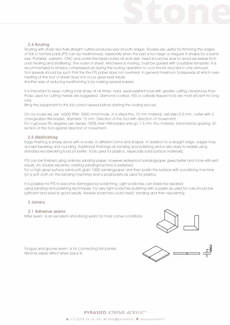
3.1 Adhesive seamsMiter seem: is an excellent and strong seam for most corner conditions
Tongue and groove seem: is for connecting flat panels. Minimal visible effect when back lit.
Stone
% +31(0)58-76 76 100 ) sa les@pyras ied .n l t www.pyr as ied .n l
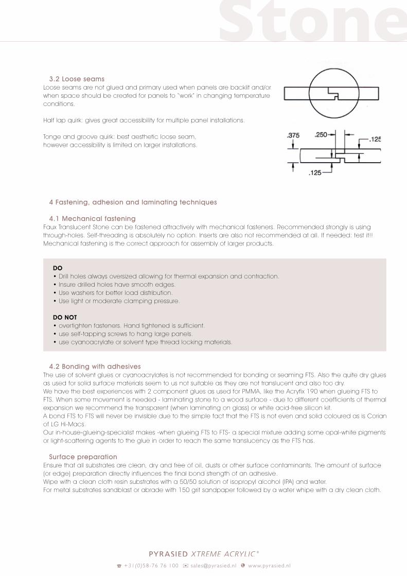
3.2 Loose seamsLoose seams are not glued and primary used when panels are backlit and/or when space should be created for panels to “work” in changing temperature conditions.
Half lap quirk: gives great accessibility for multiple panel installations.
Tonge and groove quirk: best aesthetic loose seam, however accessibility is limited on larger installations.
4 Fastening, adhesion and laminating techniques
4.1 Mechanical fasteningFaux Translucent Stone can be fastened attractively with mechanical fasteners. Recommended strongly is using through-holes. Self-threading is absolutely no option. Inser ts are also not recommended at all. If needed: test it!! Mechanical fastening is the correct approach for assembly of larger products.
DO • Drill holes always oversized allowing for thermal expansion and contraction.• Insure drilled holes have smooth edges.• Use washers for better load distribution.• Use light or moderate clamping pressure.
DO NOT• over tighten fasteners. Hand tightened is sufficient.• use self-tapping screws to hang large panels.• use cyanoacrylate or solvent type thread locking materials.
4.2 Bonding with adhesives The use of solvent glues or cyanoacrylates is not recommended for bonding or seaming FTS. Also the quite dry glues as used for solid surface materials seem to us not suitable as they are not translucent and also too dry. We have the best experiences with 2 component glues as used for PMMA, like the Acryfix 190 when glueing FTS to FTS. When some movement is needed - laminating stone to a wood surface - due to different coefficients of thermal expansion we recommend the transparent (when laminating on glass) or white acid-free silicon kit. A bond FTS to FTS will never be invisible due to the simple fact that the FTS is not even and solid coloured as is Corian of LG Hi-Macs. Our in-house-glueing-specialist makes -when glueing FTS to FTS- a special mixture adding some opal-white pigments or light-scattering agents to the glue in order to reach the same translucency as the FTS has.
Surface preparationEnsure that all substrates are clean, dry and free of oil, dusts or other surface contaminants. The amount of surface (or edge) preparation directly influences the final bond strength of an adhesive.Wipe with a clean cloth resin substrates with a 50/50 solution of isopropyl alcohol (IPA) and water.For metal substrates sandblast or abrade with 150 grit sandpaper followed by a water whipe with a dry clean cloth.

Stone
% +31(0)58-76 76 100 ) sa les@pyras ied .n l t www.pyr as ied .n l
Directions for use Download the instructions for using the Acrylic 190 from the site www.acryfix.com. Also the safety-datasheets can be found there. The glue can be supplied by us or by your local Evonik representative. For the silicon kit when making transparent or translucent bonds: we have good experience with Soudal Silglaze N. Website is www.soudalgroup.com/global-gateway/. Or choose another neutral kit. Follow the instructions of the supplier. In general: the thickness of the kit-layer should be the same as the expected difference in expansion between the two materials. For not-visible bonds use a construction-kit that stays permanent flexible and can not be seen through the FTS.
When bonding the edges of FTS panels, first mask the face of the panels with masking tape closest to the edges to be bonded. With acrylic glue do not use PVC-tape. We use a PE-tape with an acrylic adhesion layer. During the curing of the glue only slight pressure should be applied on the sheet near the bond. To much pressure will lead to tension and possible cracks in the sheet!Be careful with sheets having par ts removed by milling, for example in order to attach below the FTS-panel a washbas-sin. All inside corners should be rounded with minimal R=5 mm to avoid stressconcentration and cracking from the inside of corners!
4.3 Bonding with VHB or PE-foamtapes Several VHB tapes can be used to adhere FTS to a variety of substrates while still achieving desirable aesthetics. Clear 3M tape 4910 or 4905 are just 2 examples. This tape can be used to attach stone to sealed wood, sealed ceramics, metal, glass and some other plastics. VHB tape is UV stable and can be used in interior and exterior conditions as well in the toughest environmental conditions. This tape provides an excellent seal against moisture, however splices or seams in the tape may require additional sealing. The tape can tolerate some shear extension due to substrate move-ment from thermal expansion or contraction.
Special surface preparation is absolutely needed before applying VHB tape to an FTS panel. First cleaning with the 50/50 percent solution isopropyl alcohol (IPA) and water. Next the stone surface to be used where the tape will be ap-plied should be primed with -for example- 3M primer 94. Follow the manufacturers directions on how to safely handle and apply this primer. After the area has been primed and is dry, the tape can be applied to the first surface. Only handle the tape by the edges and apply firm presssure to the tape using a roller. Attach the second bonding substrate and apply pressure on the finished joint with a roller. Apply real firm application pressure to the total length of the taped area to develop good adhesive contact and to improve the bond strength. Bond strength will increase over time with 90% of the ultimate strength developing after 24 hours and full strength after 3 days. Ultimate bond strength can be achieved more quickly by exposure to higher temperatures.
If the entire weight of a FTS panel is supported by the VHB tape, a minimum of 50cm2 should be used for every kilo of material to be supported. Testing is highly recommended, especially when bonding to other nonmetal (porous) substrates.
DO• Seal porous materials like cement and wood before bonding.• Keep tape clean and handle by the edges.• Make sure both surfaces are clean and dry.• Use 50/50 isopropyl/watersolution for metal and plastic surfaces.• Apply a suitable primer like 3M 94.• Apply primer to first surface and apply FIRM pressure.• Remove liner and apply to second surface.• Apply very firm pressure to the whole bond line.• Wait 72 hours until tape has reached full adhesion strengt.

Stone
% +31(0)58-76 76 100 ) sa les@pyras ied .n l t www.pyr as ied .n l
4.4 Silicone sealantsAcidfree transparent siliconsealant/kit can be used for lamination of Faux Translucent Stone to another transparent surface. Follow the instructions of the silicone-supplier and use if needed a primer. Care should be taken to allow for enough thickness of the silicon layer to allow for the needed difference in expansion and contraction of the different materials due to temperature differences.
We have positive experiences also when using this kind of kit when bonding FTS to non-transparent surfaces. Of course care should be taken - as usual - that both surfaces are flat, clean and dust-free.
Silicon sealents are very useful when making bigger constructions. The par ts of the construction should be allowed some space for the expansion and contraction and using silicon kit to join the par ts is an elegant and proven way to allow the material to do so.
Silicon kits should not be used underwater or in food contact situations. Also it is not suitable for bonding with surfaces that can corrode like milled aluminium or bare steel. The cure depth of the silicon layer should not exceed 9 mm from the airside.
4.5 High-tack kitsWith high-tack kits we do not have enough experience to give a proper advice. Make sure you use high-tack kits wich can’t be seen through the sheet. These kits are suitable as long as they stay flexible on long term. Of course this flexi-bility is needed because of differences in coefficients of expansion of the FTS versus the substrate. When the substrate has the same coefficient of expansion or when the application is in an environment with a 100% stable temperature, no flexibility is needed.
5 Warm and cold bending FTS is NOT suitable for blow-moulding or vacuumforming. To be honest: we did not even try to do so.However cold bending will even happen when you would not like it to happen: using to large surfaces without proper support. See the appendix 1 with the tests and theoretical finite element analysis.
Warm bending using an oven, a mould and/or vacuumequipment can be done. We do not recommend at all to try to bend a radius smaller them 800 mm when using 10 mm thick FTS. Two axis bending: just completely forget it. If a complex shape is needed it is better to ask our production facility to “cast” this shape using some kind of mould.
The procedure we use for 10 mm Faux Alabaster is as below. The main problems are that when heated too high or/and too long the material will change color a bit. Alabaster will yellow. The other problem is that the material will crack trying to make too small radii at too low a temperature. We do not yet have experience with vacuumtables, maybe this will make smaller radii possible. (We do expect this indeed)
One advantage heat-bending the FTS is that it does not shrink, in contrast to materials as PMMA, PETG or PC.
Procedure for bending 10 mm:• do not predrying, is not needed.• do full inspection of surface quality and color, also with light behind the sheet.• check color of different par ts to be bended. Are they from the same batch? Identical colors?• the side that will be directed to the viewer is the side that should be laying on the mold. The backside if on the mold the side that is directed to the viewer. So this decides wether the mould will be positive or negative.• make the mold with bend-MDF 8 mm and ribs separated from eachother 200 mm max.• cover the mold with fabric as used for the inside of gloves (we can supply this).• put the mold with the sheet in a preheated electric oven with an even temperature distribution at 110 0C during 35 minutes.
Stone
% +31(0)58-76 76 100 ) sa les@pyras ied .n l t www.pyr as ied .n l
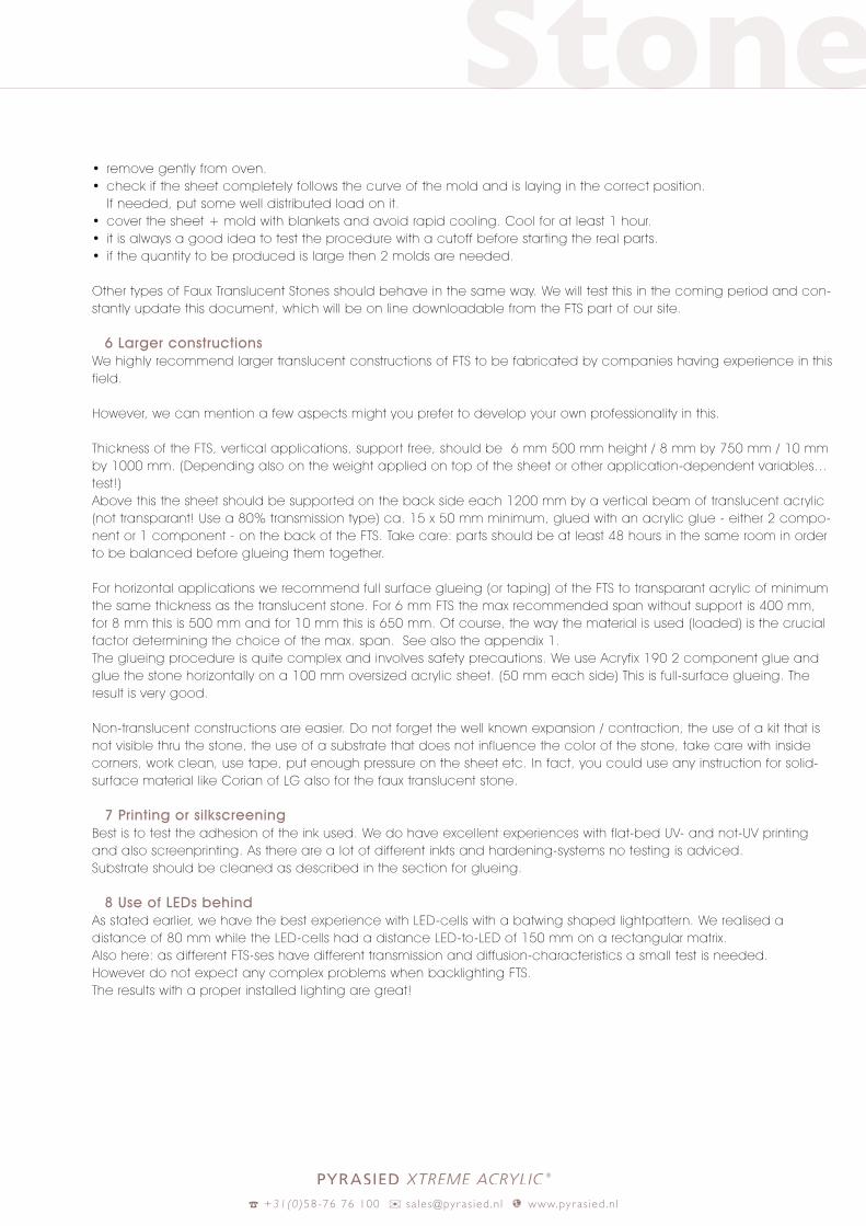
• remove gently from oven.• check if the sheet completely follows the curve of the mold and is laying in the correct position. If needed, put some well distributed load on it.• cover the sheet + mold with blankets and avoid rapid cooling. Cool for at least 1 hour.• it is always a good idea to test the procedure with a cutoff before star ting the real par ts.• if the quantity to be produced is large then 2 molds are needed.
Other types of Faux Translucent Stones should behave in the same way. We will test this in the coming period and con-stantly update this document, which will be on line downloadable from the FTS par t of our site.
6 Larger constructionsWe highly recommend larger translucent constructions of FTS to be fabricated by companies having experience in this field.
However, we can mention a few aspects might you prefer to develop your own professionality in this.
Thickness of the FTS, ver tical applications, support free, should be 6 mm 500 mm height / 8 mm by 750 mm / 10 mm by 1000 mm. (Depending also on the weight applied on top of the sheet or other application-dependent variables…test!) Above this the sheet should be supported on the back side each 1200 mm by a ver tical beam of translucent acrylic (not transparant! Use a 80% transmission type) ca. 15 x 50 mm minimum, glued with an acrylic glue - either 2 compo-nent or 1 component - on the back of the FTS. Take care: par ts should be at least 48 hours in the same room in order to be balanced before glueing them together.
For horizontal applications we recommend full surface glueing (or taping) of the FTS to transparant acrylic of minimum the same thickness as the translucent stone. For 6 mm FTS the max recommended span without support is 400 mm, for 8 mm this is 500 mm and for 10 mm this is 650 mm. Of course, the way the material is used (loaded) is the crucial factor determining the choice of the max. span. See also the appendix 1.The glueing procedure is quite complex and involves safety precautions. We use Acryfix 190 2 component glue and glue the stone horizontally on a 100 mm oversized acrylic sheet. (50 mm each side) This is full-surface glueing. The result is very good.
Non-translucent constructions are easier. Do not forget the well known expansion / contraction, the use of a kit that is not visible thru the stone, the use of a substrate that does not influence the color of the stone, take care with inside corners, work clean, use tape, put enough pressure on the sheet etc. In fact, you could use any instruction for solid-surface material like Corian of LG also for the faux translucent stone.
7 Printing or silkscreening Best is to test the adhesion of the ink used. We do have excellent experiences with flat-bed UV- and not-UV printing and also screenprinting. As there are a lot of different inkts and hardening-systems no testing is adviced. Substrate should be cleaned as described in the section for glueing.
8 Use of LEDs behindAs stated earlier, we have the best experience with LED-cells with a batwing shaped lightpattern. We realised a distance of 80 mm while the LED-cells had a distance LED-to-LED of 150 mm on a rectangular matrix. Also here: as different FTS-ses have different transmission and diffusion-characteristics a small test is needed. However do not expect any complex problems when backlighting FTS.The results with a proper installed lighting are great!

Stone
% +31(0)58-76 76 100 ) sa les@pyras ied .n l t www.pyr as ied .n l
9 Certifications
Fire behavior
Bs1do according to (N)EN 13501,tested by Peutz Laboratory for Firesafety April 2016. Material can be used safe everywhere.
Food safetysamples have been tested by Merieux NutriSciences June 2016. Material approved according to directive 10/2011: EC 1935/2004 and EC 023/2006.
Disclaimer: as usual with this kind of documents: the text above is made in all honesty and we really try to help you getting good results when fabricating our material. But: it is your own responsabilty, fully, in all aspects and dimensions, and in relation to all regulations and laws. Convince yourself that what you do, how you do it and the tools and equip-ment you use are save and fit for the intended purpose. Appendix 1: Testing the deflexion and finite element analysis.

Stone
% +31(0)58-76 76 100 ) sa les@pyras ied .n l t www.pyr as ied .n l
Appendix 1
1.1 Measurements
We star t with flat sheets.
Setup 1: 10 mm Faux Alabaster, 200 x 600 mm, both shor t ends supported. Free over 530 mm.Result with no load after 1 week at 21oC: 1 mm deflection. Long term expectation 2 mm.
Setup 2: 10 mm Faux Alabaster + 10 mm cast acrylic, 200 x 600 mm, “glued” using 7 strips 10 mm wide 0.5 mm thick 3M clear VHB tape, both shor t end supported. Free over 530 mm.Result with no load after 1 week at 21oC: 0.3 mm deflection. Long term expectation 0.6 mm.
Setup 3: 10 mm Faux Alabast, 700 x 700 mm, 2 sides supported. Free over 625 mm.Result with no load after 1 week at 21oC: 1 mm deflection, long term 2 mm.Result with 8 kg load in middle of sheet: after 2 days 1.5 mm extra deflection. Long term 3 mm extra deflection, giving a total of 5 mm.
Setup 4: same as 3 mm, but 4 sides supported.No deflection. Long term maybe 1 mm.
600
200
200
700
700
1200
10 mm Faux Alabaster
2 sided support
530
1
600
6 mm Faux Alabaster
2 sided support
530
6
1200 x 1200 x 10 Faux Alabaster
7
600
10 mm Faux Alabaster + 10 mm cast acrylic glue together
2 sided support
530
2
700
10 mm Faux Alabaster
2 sided support
625
3
1200
10 mm Faux Alabaster
2 sided support
5
700
10 mm Faux Alabaster
4 sided support
4
600
200
200
700
700
1200
10 mm Faux Alabaster
2 sided support
530
1
600
6 mm Faux Alabaster
2 sided support
530
6
1200 x 1200 x 10 Faux Alabaster
7
600
10 mm Faux Alabaster + 10 mm cast acrylic glue together
2 sided support
530
2
700
10 mm Faux Alabaster
2 sided support
625
3
1200
10 mm Faux Alabaster
2 sided support
5
700
10 mm Faux Alabaster
4 sided support
4

Stone
% +31(0)58-76 76 100 ) sa les@pyras ied .n l t www.pyr as ied .n l
Setup 5: 10 mm Faux Alabaster, 1200 x 1200 mm, both sides supported, free over 1130 mm.Result with no load 6 mm deflection. Long term expectation is double! Result with 11 kg load in middle: after 2 days extra 5 mm. Long term extra 10 mm!
Setup 6: 6 mm Faux Alabast, 600 x 600 mm, both sides supported, free over 530 mm.Result with no load after 1 week at 21oC 1 mm deflection. Long term 2 a 3 mm.
Setup 7 is a ver tical sheet 10 mm Faux Alabaster 1200 x 1200, supported bottom and top. After 1 week still fully flat, no load.
Conclusion: 2 sided support, 650 mm wide seems to be a practical limit for a horizontal surface without constant load for a 10 mm thick sheet. Long term expectation 3 mm.
Additional testing has been done with a 10 kg block of lead in the centre of setups 5 and 6. After 14 days both setups in final test fail, material breaks. In second test no failure. Conclusion: Faux translucent stone is NOT suitable, even fail, when used with heavy concentrated loads. Do never use it as a bar top or counter with something heavy on it without proper additional support!
600
200
200
700
700
1200
10 mm Faux Alabaster
2 sided support
530
1
600
6 mm Faux Alabaster
2 sided support
530
6
1200 x 1200 x 10 Faux Alabaster
7
600
10 mm Faux Alabaster + 10 mm cast acrylic glue together
2 sided support
530
2
700
10 mm Faux Alabaster
2 sided support
625
3
1200
10 mm Faux Alabaster
2 sided support
5
700
10 mm Faux Alabaster
4 sided support
4
600
200
200
700
700
1200
10 mm Faux Alabaster
2 sided support
530
1
600
6 mm Faux Alabaster
2 sided support
530
6
1200 x 1200 x 10 Faux Alabaster
7
600
10 mm Faux Alabaster + 10 mm cast acrylic glue together
2 sided support
530
2
700
10 mm Faux Alabaster
2 sided support
625
3
1200
10 mm Faux Alabaster
2 sided support
5
700
10 mm Faux Alabaster
4 sided support
4
Stone
% +31(0)58-76 76 100 ) sa les@pyras ied .n l t www.pyr as ied .n l
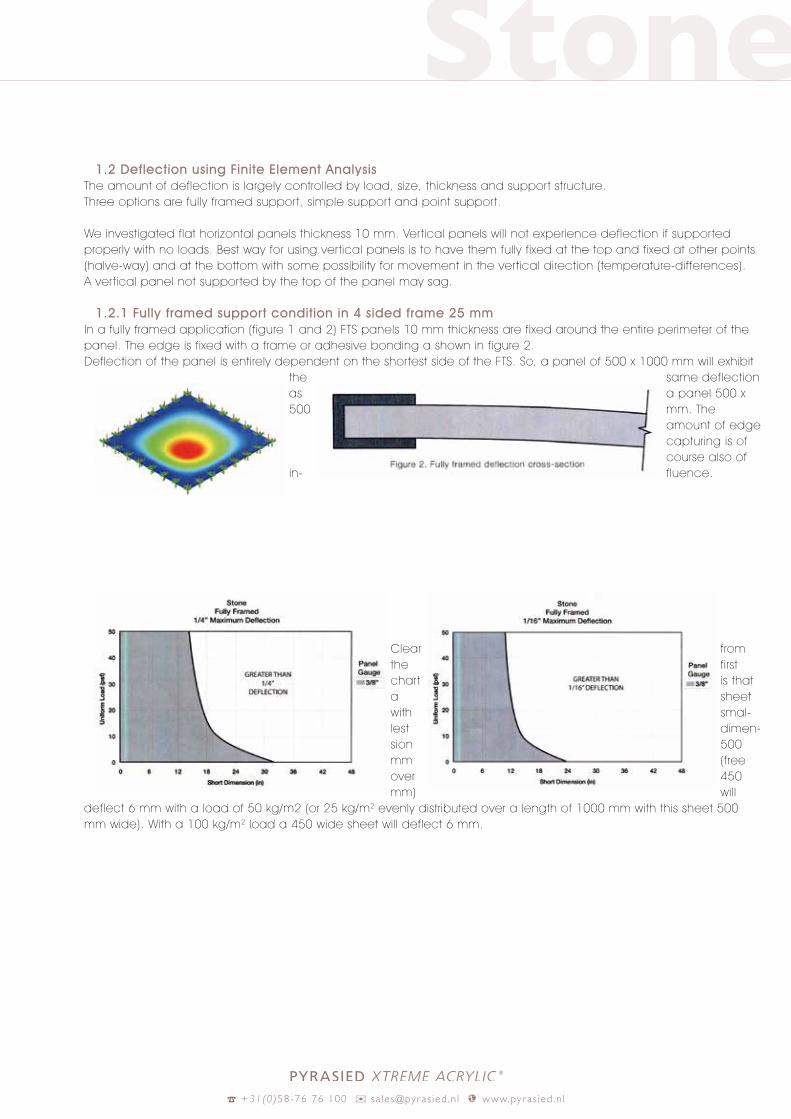
1.2 Deflection using Finite Element Analysis
The amount of deflection is largely controlled by load, size, thickness and support structure.Three options are fully framed support, simple support and point support.
We investigated flat horizontal panels thickness 10 mm. Ver tical panels will not experience deflection if supported properly with no loads. Best way for using ver tical panels is to have them fully fixed at the top and fixed at other points (halve-way) and at the bottom with some possibility for movement in the ver tical direction (temperature-differences). A ver tical panel not supported by the top of the panel may sag.
1.2.1 Fully framed support condition in 4 sided frame 25 mmIn a fully framed application (figure 1 and 2) FTS panels 10 mm thickness are fixed around the entire perimeter of the panel. The edge is fixed with a frame or adhesive bonding a shown in figure 2. Deflection of the panel is entirely dependent on the shor test side of the FTS. So, a panel of 500 x 1000 mm will exhibit
the same deflection as a panel 500 x 500 mm. The
amount of edge capturing is of course also of
in- fluence.
Clear from the first char t is that a sheet with smal-lest dimen-sion 500 mm (free over 450 mm) will
deflect 6 mm with a load of 50 kg/m2 (or 25 kg/m2 evenly distributed over a length of 1000 mm with this sheet 500 mm wide). With a 100 kg/m2 load a 450 wide sheet will deflect 6 mm.
Stone
% +31(0)58-76 76 100 ) sa les@pyras ied .n l t www.pyr as ied .n l
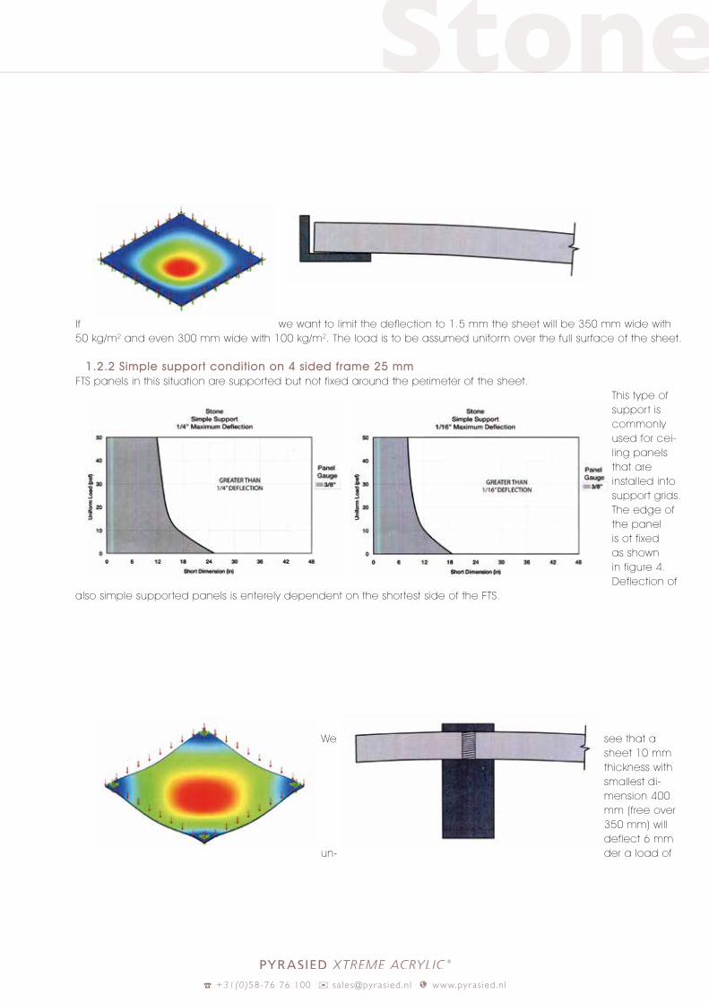
If we want to limit the deflection to 1.5 mm the sheet will be 350 mm wide with 50 kg/m2 and even 300 mm wide with 100 kg/m2. The load is to be assumed uniform over the full surface of the sheet.
1.2.2 Simple support condition on 4 sided frame 25 mmFTS panels in this situation are supported but not fixed around the perimeter of the sheet.
This type of support is commonly used for cei-ling panels that are installed into support grids. The edge of the panel is ot fixed as shown in figure 4. Deflection of
also simple supported panels is enterely dependent on the shor test side of the FTS.
We see that a sheet 10 mm thickness with smallest di-mension 400 mm (free over 350 mm) will deflect 6 mm
un- der a load of
Stone
% +31(0)58-76 76 100 ) sa les@pyras ied .n l t www.pyr as ied .n l
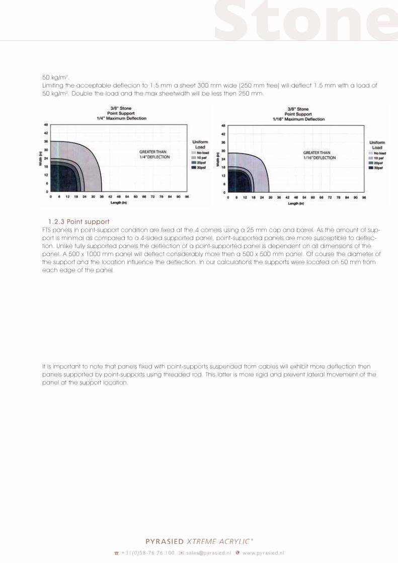
50 kg/m2.Limiting the acceptable deflecion to 1.5 mm a sheet 300 mm wide (250 mm free) will deflect 1.5 mm with a load of 50 kg/m2. Double the load and the max sheetwidth will be less then 250 mm.
1.2.3 Point support FTS panels in point-support condition are fixed at the 4 corners using a 25 mm cap and barrel. As the amount of sup-por t is minimal as compared to a 4-sided supported panel, point-supported panels are more susceptible to deflec-tion. Unlike fully supported panels the deflection of a point-supported panel is dependent on all dimensions of the panel. A 500 x 1000 mm panel will deflect considerably more then a 500 x 500 mm panel. Of course the diameter of the support and the location influence the deflection. In our calculations the supports were located on 50 mm from each edge of the panel.
It is important to note that panels fixed with point-supports suspended from cables will exhibit more deflection then panels supported by point-supports using threaded rod. This latter is more rigid and prevent lateral movement of the panel at the support location.