fcc part 15.247 test report · fcc part 15b jbp submissions with fcc id: 2ah4j-rkh-tri-01. test...
TRANSCRIPT

Note: This test report is prepared for the customer shown above and for the equipment described herein. It may not be duplicated or used in part without prior written consent from Bay Area Compliance Laboratories Corp.
FCC PART 15.247
TEST REPORT
For
Consumer 2.0
1180 South Beverly Drive Suite 300, Los Angeles, CA, 90035, United States
FCC ID: 2AH4J-RKH-TRI-01
Report Type:
Original Report
Product Type:
Rently Keyless Hub
Report Number:
RSZ170425001-00C
Report Date:
2017-07-31
Reviewed By:
Oscar Ye Engineer
Prepared By:
Bay Area Compliance Laboratories Corp. (Kunshan) No.248 Chenghu Road, Kunshan, Jiangsu province, China Tel: +86-0512-86175000 Fax: +86-0512-88934268 www.baclcorp.com.cn
Bay Area Compliance Laboratories Corp. (Kunshan) Report No.: RSZ170425001-00C
FCC Part 15.247 Page 2 of 46
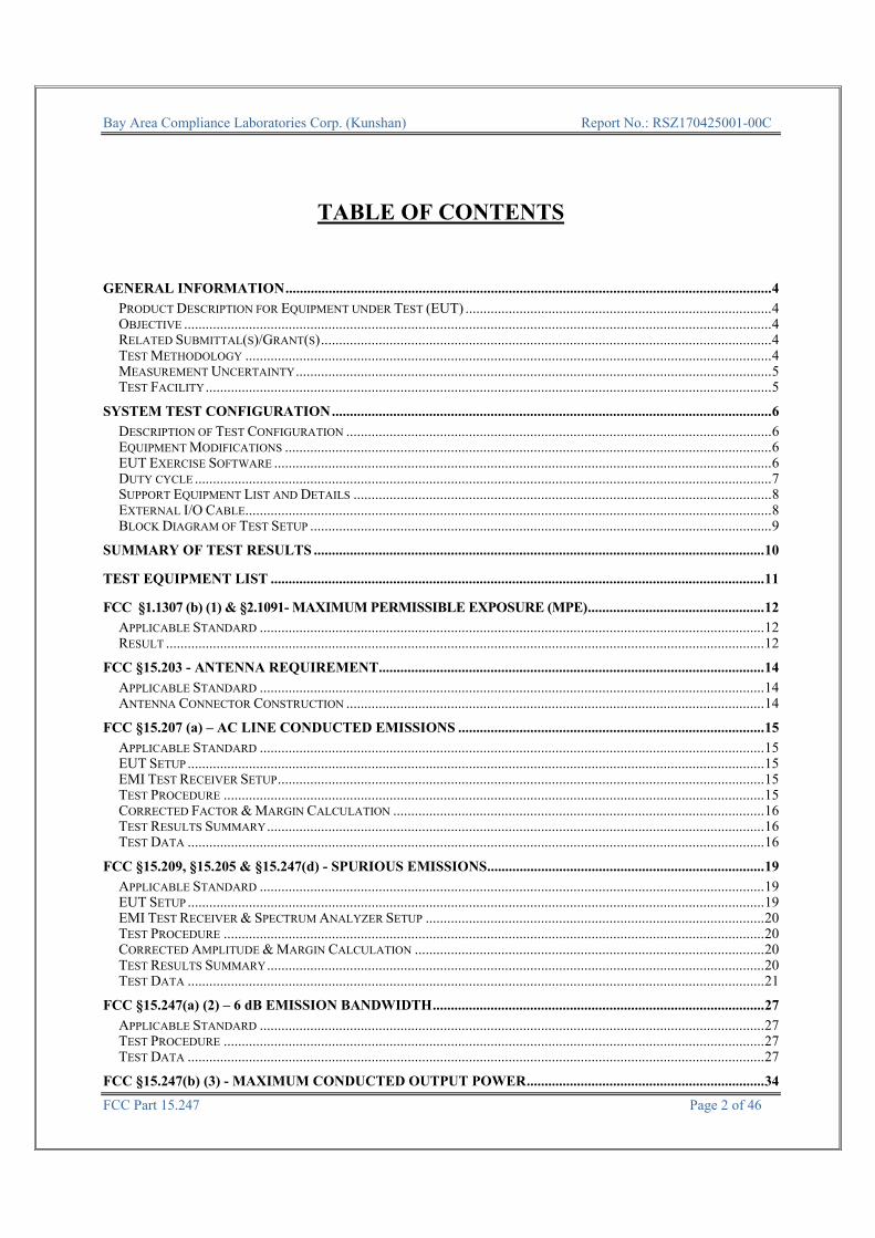
TABLE OF CONTENTS
GENERAL INFORMATION ....................................................................................................................................... 4
PRODUCT DESCRIPTION FOR EQUIPMENT UNDER TEST (EUT) ..................................................................................... 4 OBJECTIVE ................................................................................................................................................................... 4 RELATED SUBMITTAL(S)/GRANT(S) ............................................................................................................................. 4 TEST METHODOLOGY .................................................................................................................................................. 4 MEASUREMENT UNCERTAINTY .................................................................................................................................... 5 TEST FACILITY ............................................................................................................................................................. 5
SYSTEM TEST CONFIGURATION .......................................................................................................................... 6
DESCRIPTION OF TEST CONFIGURATION ...................................................................................................................... 6 EQUIPMENT MODIFICATIONS ....................................................................................................................................... 6 EUT EXERCISE SOFTWARE .......................................................................................................................................... 6 DUTY CYCLE ................................................................................................................................................................ 7 SUPPORT EQUIPMENT LIST AND DETAILS .................................................................................................................... 8 EXTERNAL I/O CABLE .................................................................................................................................................. 8 BLOCK DIAGRAM OF TEST SETUP ................................................................................................................................ 9
SUMMARY OF TEST RESULTS ............................................................................................................................. 10
TEST EQUIPMENT LIST ......................................................................................................................................... 11
FCC §1.1307 (b) (1) & §2.1091- MAXIMUM PERMISSIBLE EXPOSURE (MPE) ................................................. 12
APPLICABLE STANDARD ............................................................................................................................................ 12 RESULT ...................................................................................................................................................................... 12
FCC §15.203 - ANTENNA REQUIREMENT ........................................................................................................... 14
APPLICABLE STANDARD ............................................................................................................................................ 14 ANTENNA CONNECTOR CONSTRUCTION .................................................................................................................... 14
FCC §15.207 (a) – AC LINE CONDUCTED EMISSIONS ..................................................................................... 15
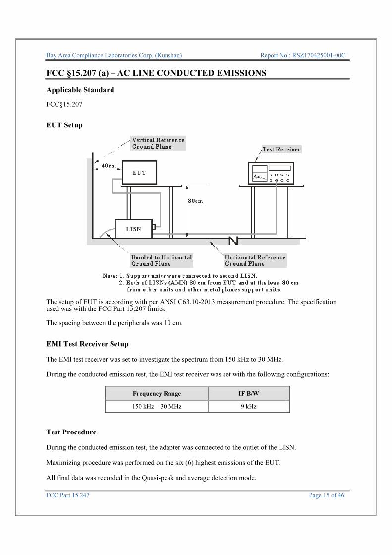
APPLICABLE STANDARD ............................................................................................................................................ 15 EUT SETUP ................................................................................................................................................................ 15 EMI TEST RECEIVER SETUP ....................................................................................................................................... 15 TEST PROCEDURE ...................................................................................................................................................... 15 CORRECTED FACTOR & MARGIN CALCULATION ....................................................................................................... 16 TEST RESULTS SUMMARY .......................................................................................................................................... 16 TEST DATA ................................................................................................................................................................ 16
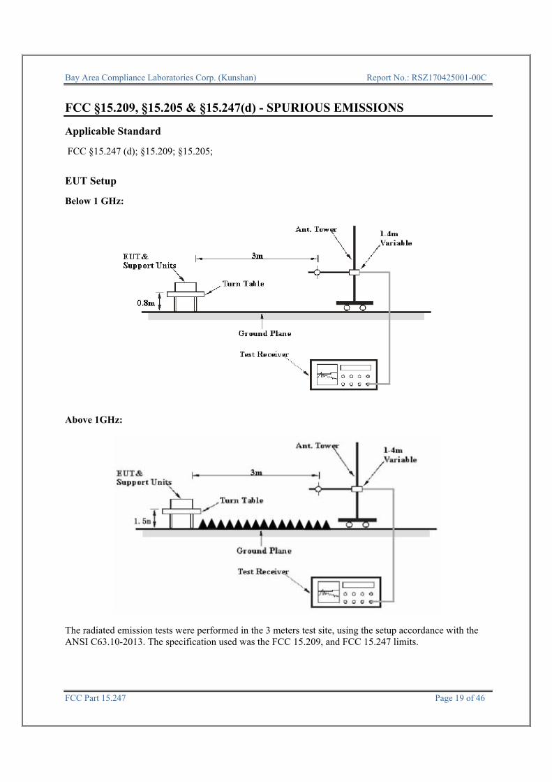
FCC §15.209, §15.205 & §15.247(d) - SPURIOUS EMISSIONS ............................................................................. 19
APPLICABLE STANDARD ............................................................................................................................................ 19 EUT SETUP ................................................................................................................................................................ 19 EMI TEST RECEIVER & SPECTRUM ANALYZER SETUP .............................................................................................. 20 TEST PROCEDURE ...................................................................................................................................................... 20 CORRECTED AMPLITUDE & MARGIN CALCULATION ................................................................................................. 20 TEST RESULTS SUMMARY .......................................................................................................................................... 20 TEST DATA ................................................................................................................................................................ 21
FCC §15.247(a) (2) – 6 dB EMISSION BANDWIDTH ............................................................................................ 27
APPLICABLE STANDARD ............................................................................................................................................ 27 TEST PROCEDURE ...................................................................................................................................................... 27 TEST DATA ................................................................................................................................................................ 27
FCC §15.247(b) (3) - MAXIMUM CONDUCTED OUTPUT POWER .................................................................. 34

Bay Area Compliance Laboratories Corp. (Kunshan) Report No.: RSZ170425001-00C
FCC Part 15.247 Page 3 of 46
APPLICABLE STANDARD ............................................................................................................................................ 34 TEST PROCEDURE ...................................................................................................................................................... 34 TEST DATA ................................................................................................................................................................ 34
FCC §15.247(d) – 100 kHz BANDWIDTH OF FREQUENCY BAND EDGE ....................................................... 36
APPLICABLE STANDARD ............................................................................................................................................ 36 TEST PROCEDURE ...................................................................................................................................................... 36 TEST DATA ................................................................................................................................................................ 36
FCC §15.247(e) - POWER SPECTRAL DENSITY ................................................................................................. 40
APPLICABLE STANDARD ............................................................................................................................................ 40 TEST PROCEDURE ...................................................................................................................................................... 40 TEST DATA ................................................................................................................................................................ 40
Bay Area Compliance Laboratories Corp. (Kunshan) Report No.: RSZ170425001-00C
FCC Part 15.247 Page 4 of 46
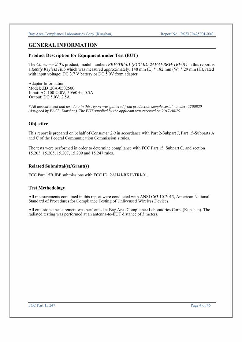
GENERAL INFORMATION Product Description for Equipment under Test (EUT) The Consumer 2.0’s product, model number: RKH-TRI-01 (FCC ID: 2AH4J-RKH-TRI-01) in this report is a Rently Keyless Hub which was measured approximately: 148 mm (L) * 182 mm (W) * 29 mm (H), rated with input voltage: DC 3.7 V battery or DC 5.0V from adapter. Adapter Information: Model: ZD120A-0502500 Input: AC 100-240V, 50/60Hz, 0.5A Output: DC 5.0V, 2.5A * All measurement and test data in this report was gathered from production sample serial number: 1700820 (Assigned by BACL, Kunshan). The EUT supplied by the applicant was received on 2017-04-25. Objective This report is prepared on behalf of Consumer 2.0 in accordance with Part 2-Subpart J, Part 15-Subparts A and C of the Federal Communication Commission’s rules. The tests were performed in order to determine compliance with FCC Part 15, Subpart C, and section 15.203, 15.205, 15.207, 15.209 and 15.247 rules. Related Submittal(s)/Grant(s) FCC Part 15B JBP submissions with FCC ID: 2AH4J-RKH-TRI-01. Test Methodology All measurements contained in this report were conducted with ANSI C63.10-2013, American National Standard of Procedures for Compliance Testing of Unlicensed Wireless Devices. All emissions measurement was performed at Bay Area Compliance Laboratories Corp. (Kunshan). The radiated testing was performed at an antenna-to-EUT distance of 3 meters.
Bay Area Compliance Laboratories Corp. (Kunshan) Report No.: RSZ170425001-00C
FCC Part 15.247 Page 5 of 46
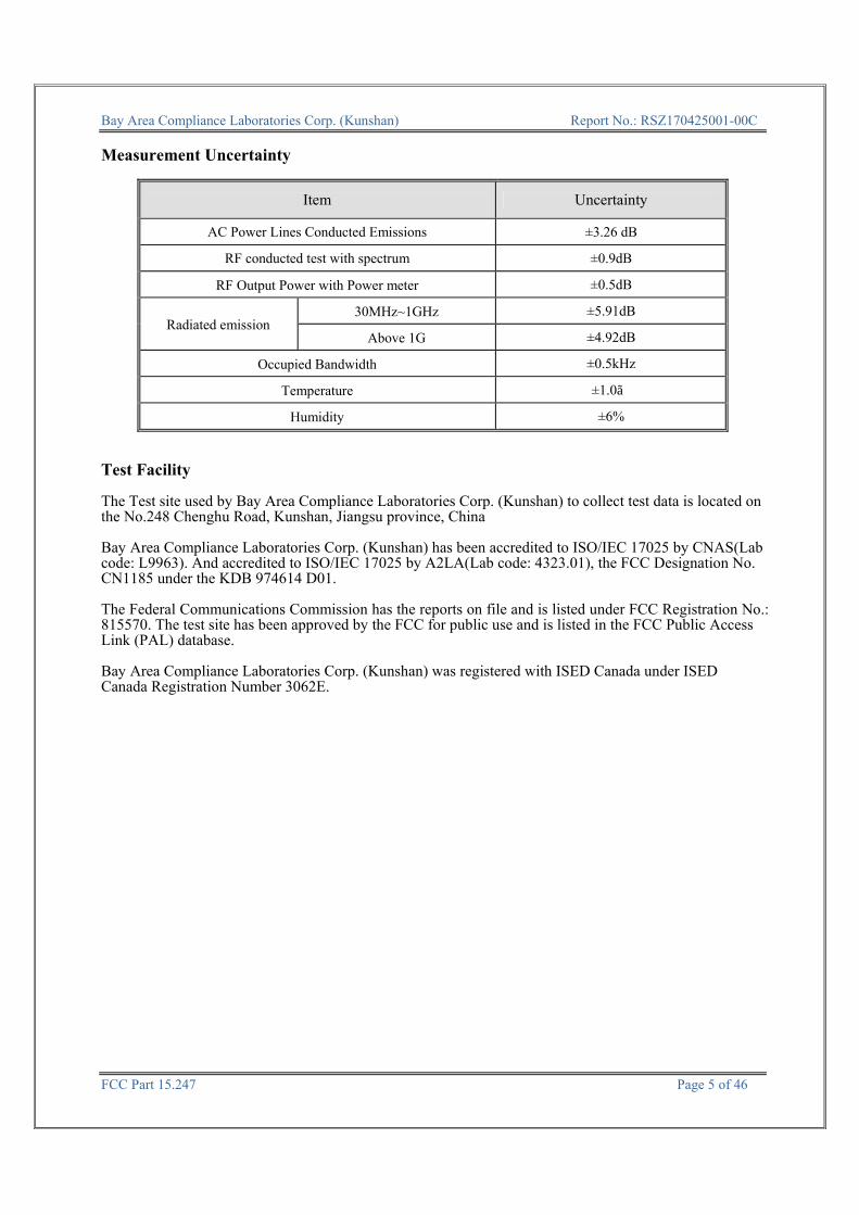
Measurement Uncertainty
Item Uncertainty
AC Power Lines Conducted Emissions ±3.26 dB
RF conducted test with spectrum ±0.9dB
RF Output Power with Power meter ±0.5dB
Radiated emission 30MHz~1GHz ±5.91dB
Above 1G ±4.92dB
Occupied Bandwidth ±0.5kHz
Temperature ±1.0℃
Humidity ±6%
Test Facility The Test site used by Bay Area Compliance Laboratories Corp. (Kunshan) to collect test data is located on the No.248 Chenghu Road, Kunshan, Jiangsu province, China Bay Area Compliance Laboratories Corp. (Kunshan) has been accredited to ISO/IEC 17025 by CNAS(Lab code: L9963). And accredited to ISO/IEC 17025 by A2LA(Lab code: 4323.01), the FCC Designation No. CN1185 under the KDB 974614 D01. The Federal Communications Commission has the reports on file and is listed under FCC Registration No.: 815570. The test site has been approved by the FCC for public use and is listed in the FCC Public Access Link (PAL) database. Bay Area Compliance Laboratories Corp. (Kunshan) was registered with ISED Canada under ISED Canada Registration Number 3062E.
Bay Area Compliance Laboratories Corp. (Kunshan) Report No.: RSZ170425001-00C
FCC Part 15.247 Page 6 of 46
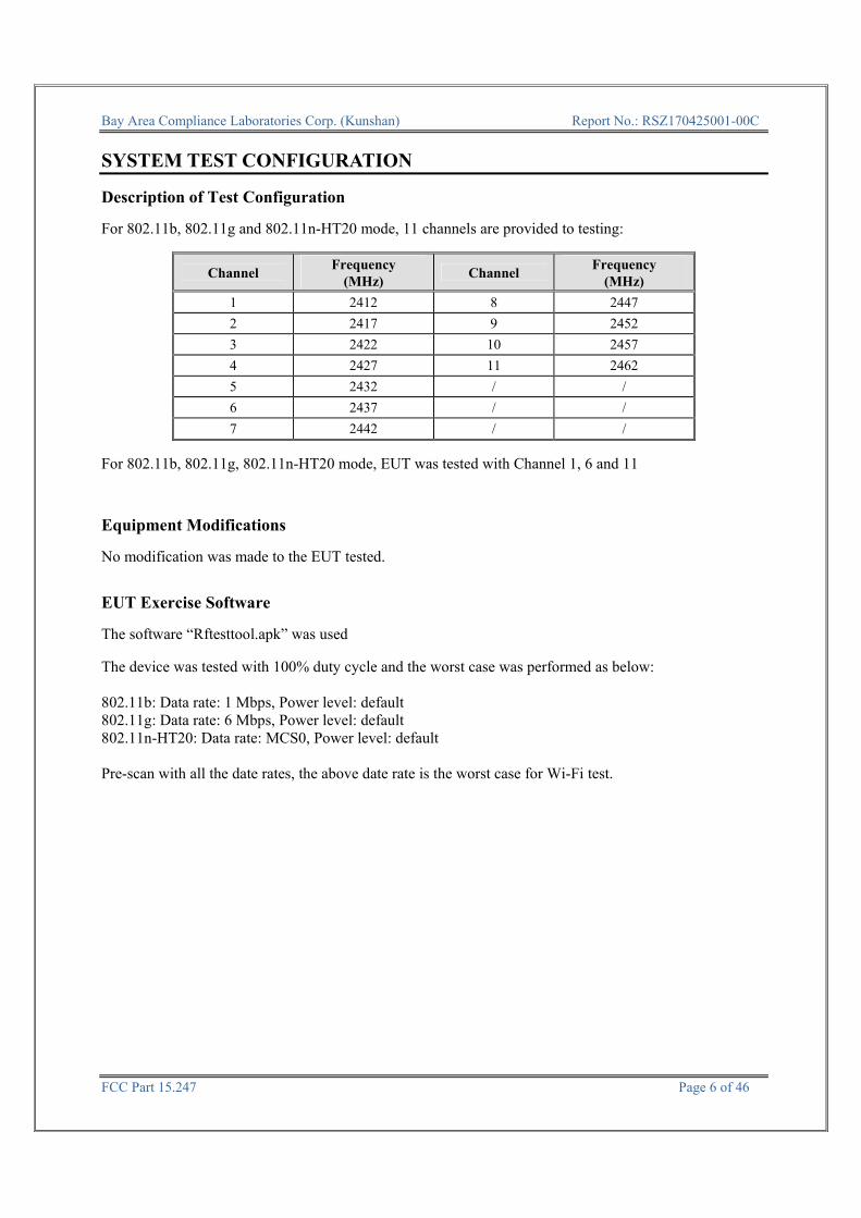
SYSTEM TEST CONFIGURATION Description of Test Configuration For 802.11b, 802.11g and 802.11n-HT20 mode, 11 channels are provided to testing:
Channel Frequency
(MHz) Channel
Frequency (MHz)
1 2412 8 2447
2 2417 9 2452
3 2422 10 2457
4 2427 11 2462
5 2432 / /
6 2437 / /
7 2442 / /
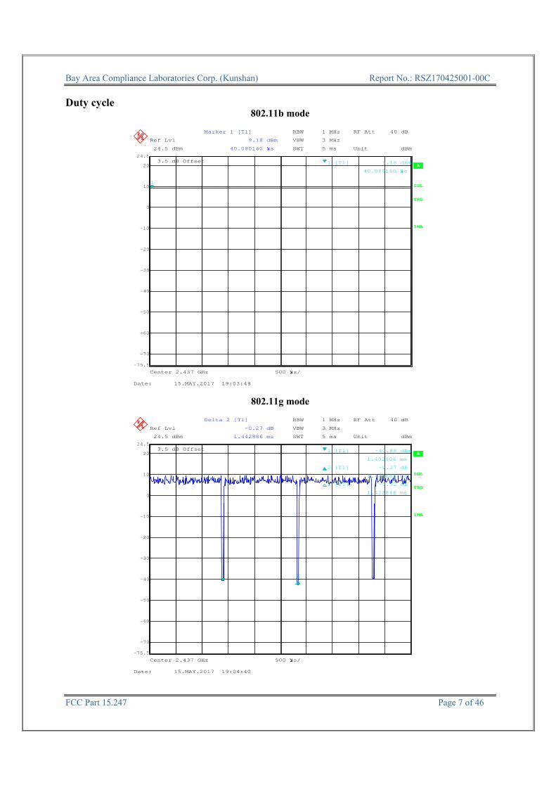
For 802.11b, 802.11g, 802.11n-HT20 mode, EUT was tested with Channel 1, 6 and 11 Equipment Modifications No modification was made to the EUT tested. EUT Exercise Software The software “Rftesttool.apk” was used The device was tested with 100% duty cycle and the worst case was performed as below: 802.11b: Data rate: 1 Mbps, Power level: default 802.11g: Data rate: 6 Mbps, Power level: default 802.11n-HT20: Data rate: MCS0, Power level: default Pre-scan with all the date rates, the above date rate is the worst case for Wi-Fi test.
Bay Area Compliance Laboratories Corp. (Kunshan) Report No.: RSZ170425001-00C
FCC Part 15.247 Page 7 of 46
Duty cycle
802.11b mode
RBW 1 MHz RF Att 40 dB
A
Unit dBm
Ref Lvl
24.5 dBm
Ref Lvl
24.5 dBm
3.5 dB Offset
VBW 3 MHz
1MA
TRG
SWT 5 ms
Center 2.437 GHz 500 s/
SGL
-70
-60
-50
-40
-30
-20
-10
0
10
20
-75.5
24.5
1
Marker 1 [T1]
9.18 dBm
40.080160 s
1 [T1] 9.18 dBm
40.080160 s
Date: 15.MAY.2017 19:03:49
802.11g mode
RBW 1 MHz RF Att 40 dB
A
Unit dBm
Ref Lvl
24.5 dBm
Ref Lvl
24.5 dBm
3.5 dB Offset
VBW 3 MHz
1MA
TRG
SWT 5 ms
Center 2.437 GHz 500 s/
SGL
-70
-60
-50
-40
-30
-20
-10
0
10
20
-75.5
24.5
1 12
Delta 2 [T1]
-0.27 dB
1.442886 ms
1 [T1] -40.88 dBm
1.402806 ms
2 [T1] -0.27 dB
1.442886 ms
1 [T1] -0.32 dB
1.422846 ms
Date: 15.MAY.2017 19:04:40

Bay Area Compliance Laboratories Corp. (Kunshan) Report No.: RSZ170425001-00C
FCC Part 15.247 Page 8 of 46
802.11n-HT20 Mode
RBW 1 MHz RF Att 40 dB
A
Unit dBm
Ref Lvl
24.5 dBm
Ref Lvl
24.5 dBm
3.5 dB Offset
VBW 3 MHz
1MA
TRG
SWT 5 ms
Center 2.437 GHz 500 s/
SGL
-70
-60
-50
-40
-30
-20
-10
0
10
20
-75.5
24.5
112
Delta 1 [T1]
-1.60 dB
1.332665 ms
1 [T1] -38.56 dBm
1.412826 ms
1 [T1] -1.60 dB
1.332665 ms
2 [T1] -2.41 dB
1.352705 ms
Date: 15.MAY.2017 19:05:17
Band Duty Cycle (%) T(us) 1/T(kHz) VBW Setting 10log(1/x)
802.11b 100 - - 10Hz 0
802.11g 99 - - 10Hz 0
802.11n-HT20 99 - - 10Hz 0
Support Equipment List and Details
External I/O Cable
Cable Description Length (m) From Port To
Un-shielding Detachable DC Cable 1.5 EUT Adapter
Un-shielding Detachable RJ45 Cable 1.5 EUT Notebook
Manufacturer Description Model Serial Number
DELL Notebook E6410 GYXJ3A00 JSD2

Bay Area Compliance Laboratories Corp. (Kunshan) Report No.: RSZ170425001-00C
FCC Part 15.247 Page 9 of 46
Block Diagram of Test Setup For conducted emission
Non-Conductive Table 80 cm above Ground Plane
LISN Adapter
Receptacle
EUT
1.5 Meters
1.0 Meter
10cm
Notebook
Bay Area Compliance Laboratories Corp. (Kunshan) Report No.: RSZ170425001-00C
FCC Part 15.247 Page 10 of 46
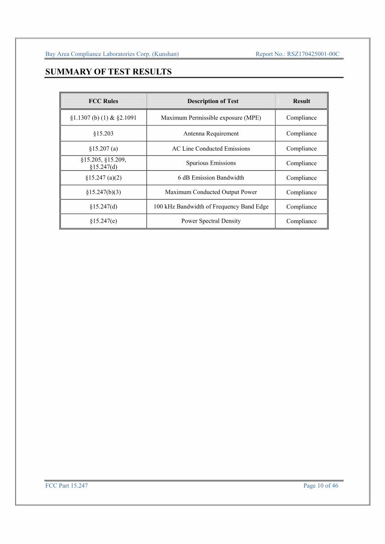
SUMMARY OF TEST RESULTS
FCC Rules Description of Test Result
§1.1307 (b) (1) & §2.1091 Maximum Permissible exposure (MPE) Compliance
§15.203 Antenna Requirement Compliance
§15.207 (a) AC Line Conducted Emissions Compliance
§15.205, §15.209, §15.247(d)
Spurious Emissions Compliance
§15.247 (a)(2) 6 dB Emission Bandwidth Compliance
§15.247(b)(3) Maximum Conducted Output Power Compliance
§15.247(d) 100 kHz Bandwidth of Frequency Band Edge Compliance
§15.247(e) Power Spectral Density Compliance

Bay Area Compliance Laboratories Corp. (Kunshan) Report No.: RSZ170425001-00C
FCC Part 15.247 Page 11 of 46
TEST EQUIPMENT LIST
Manufacturer Description Model Serial Number
Calibration Date
Calibration Due Date
AC Line Conducted test
Rohde & Schwarz EMI Test Receiver ESCS30 834115/007 2016-11-25 2017-11-25
Rohde & Schwarz LISN ESH3-Z5 862770/011 2016-10-10 2017-10-10
Rohde & Schwarz Pulse limiter ESH3-Z2 879940/0058 2016-06-19 2017-06-18
MICRO-COAX Coaxial line UFB-293B-1-0480-50X50 97F0173 2016-09-08 2017-09-08
Rohde & Schwarz CE Test software EMC 32 V 09.10.0 NCR NCR
Radiation test
Sonoma Instrunent Pre-Amplifier 330 171377 2016-12-12 2017-12-11
Rohde & Schwarz EMI Test Receiver ESCI 100195 2016-11-25 2017-11-25
Sunol Sciences Broadband Antenna JB3 A090314-2 2016-01-09 2019-01-08
Narda Pre-amplifier AFS42-00101800 2001270 2016-09-08 2017-09-08
EMCO Horn Antenna 3116 00084159 2016-10-18 2019-10-17
Rohde & Schwarz Signal Analyzer FSIQ26 100048 2016-11-25 2017-11-25
ETS Horn Antenna 3115 6229 2016-01-11 2019-01-10
R&S Auto test Software EMC32 V 09.10.0 NCR NCR
haojintech Coaxial Cable Cable-1 001 2016-12-12 2017-12-12
haojintech Coaxial Cable Cable-2 002 2016-12-12 2017-12-12
haojintech Coaxial Cable Cable-3 003 2016-12-12 2017-12-12
MICRO-COAX Coaxial Cable Cable-4 004 2016-12-12 2017-12-12
MICRO-COAX Coaxial Cable Cable-5 005 2016-12-12 2017-12-12
RF Conducted test
BACL TS 8997 Cable-01 T-KS-EMC086 T-KS-
EMC086 2016-12-09 2017-12-08
BACL RF cable KS-LAB-012 KS-LAB-012 2016-12-15 2017-12-15
WEINSCHEL 10dB Attenuator 5328 N/A 2016-06-18 2017-06-18
Agilent Power Meter N1912A MY5000492 2016-11-17 2017-11-16
Agilent Power Sensor N1921A MY54210024 2016-11-17 2017-11-16
Rohde & Schwarz Signal Analyzer FSIQ26 836131/009 2016-09-21 2017-09-21
* Statement of Traceability: Bay Area Compliance Laboratories Corp. (Kunshan) attests that all calibrations have been performed in accordance to requirements that traceable to National Primary Standards and International System of Units (SI).
Bay Area Compliance Laboratories Corp. (Kunshan) Report No.: RSZ170425001-00C
FCC Part 15.247 Page 12 of 46
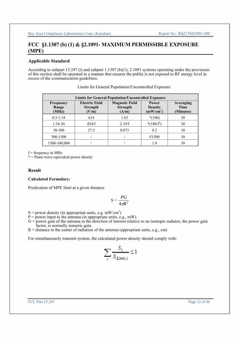
FCC §1.1307 (b) (1) & §2.1091- MAXIMUM PERMISSIBLE EXPOSURE (MPE) Applicable Standard According to subpart 15.247 (i) and subpart 1.1307 (b)(1), 2.1091 systems operating under the provisions of this section shall be operated in a manner that ensures the public is not exposed to RF energy level in excess of the communication guidelines.
Limits for General Population/Uncontrolled Exposure
Limits for General Population/Uncontrolled Exposure Frequency
Range (MHz)
Electric FieldStrength
(V/m)
Magnetic Field Strength
(A/m)
Power Density
(mW/cm2)
Averaging Time
(Minutes)
0.3-1.34 614 1.63 *(100) 30
1.34-30 824/f 2.19/f *(180/f2) 30
30-300 27.5 0.073 0.2 30
300-1500 / / f/1500 30
1500-100,000 / / 1.0 30
f = frequency in MHz * = Plane-wave equivalent power density Result Calculated Formulary: Predication of MPE limit at a given distance
S = 24 R
PG
S = power density (in appropriate units, e.g. mW/cm2) P = power input to the antenna (in appropriate units, e.g., mW). G = power gain of the antenna in the direction of interest relative to an isotropic radiator, the power gain
factor, is normally numeric gain. R = distance to the center of radiation of the antenna (appropriate units, e.g., cm) For simultaneously transmit system, the calculated power density should comply with:
Bay Area Compliance Laboratories Corp. (Kunshan) Report No.: RSZ170425001-00C
FCC Part 15.247 Page 13 of 46
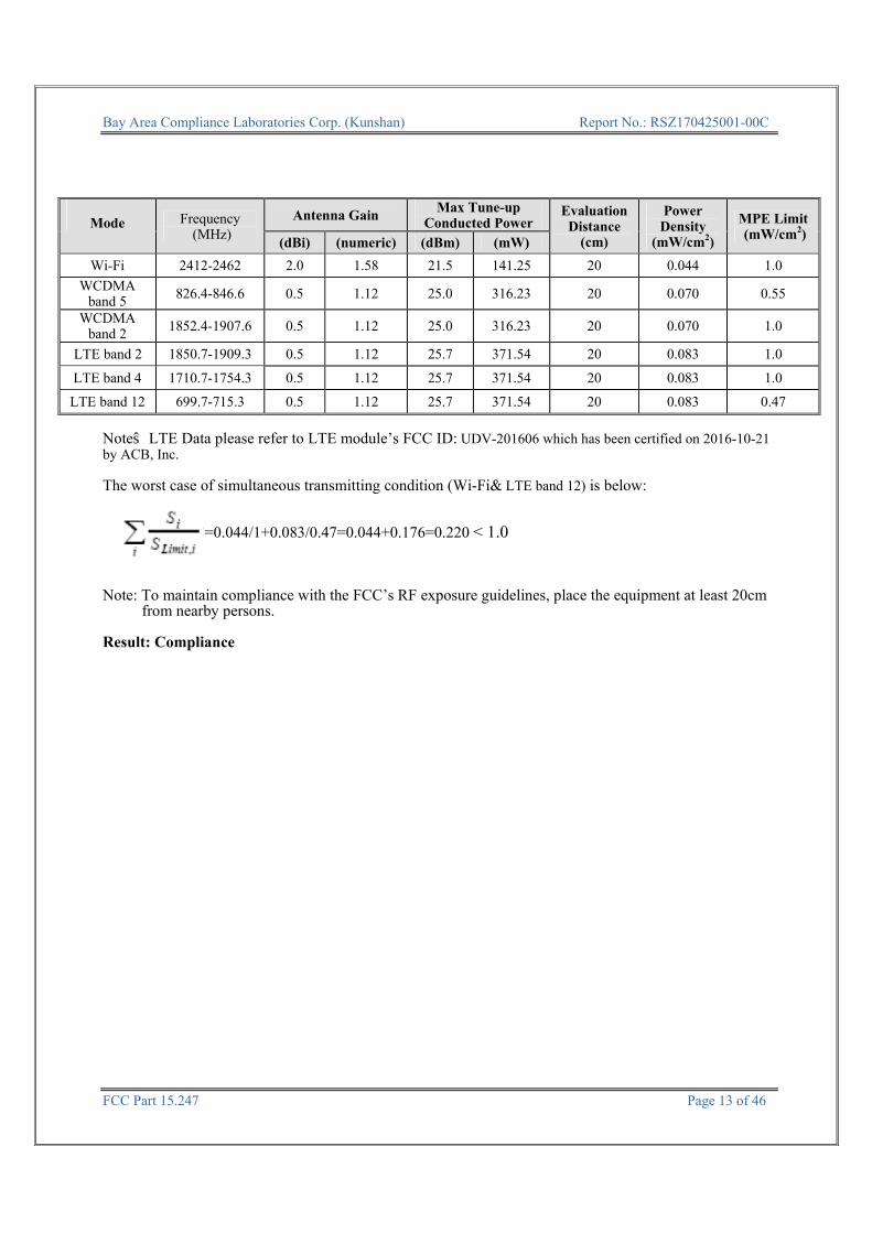
Mode Frequency (MHz)
Antenna Gain Max Tune-up
Conducted Power Evaluation Distance
(cm)
Power Density
(mW/cm2)
MPE Limit (mW/cm2)
(dBi) (numeric) (dBm) (mW)
Wi-Fi 2412-2462 2.0 1.58 21.5 141.25 20 0.044 1.0
WCDMA band 5 826.4-846.6 0.5 1.12 25.0 316.23 20 0.070 0.55
WCDMA band 2 1852.4-1907.6 0.5 1.12 25.0 316.23 20 0.070 1.0
LTE band 2 1850.7-1909.3 0.5 1.12 25.7 371.54 20 0.083 1.0
LTE band 4 1710.7-1754.3 0.5 1.12 25.7 371.54 20 0.083 1.0
LTE band 12 699.7-715.3 0.5 1.12 25.7 371.54 20 0.083 0.47
Note:LTE Data please refer to LTE module’s FCC ID: UDV-201606 which has been certified on 2016-10-21 by ACB, Inc. The worst case of simultaneous transmitting condition (Wi-Fi& LTE band 12) is below: =0.044/1+0.083/0.47=0.044+0.176=0.220 < 1.0 Note: To maintain compliance with the FCC’s RF exposure guidelines, place the equipment at least 20cm
from nearby persons. Result: Compliance
Bay Area Compliance Laboratories Corp. (Kunshan) Report No.: RSZ170425001-00C
FCC Part 15.247 Page 14 of 46
FCC §15.203 - ANTENNA REQUIREMENT Applicable Standard According to § 15.203, an intentional radiator shall be designed to ensure that no antenna other than that furnished by the responsible party shall be used with the device. The use of a permanently attached antenna or of an antenna that uses a unique coupling to the intentional radiator shall be considered sufficient to comply with the provisions of this section. The manufacturer may design the unit so that a broken antenna can be replaced by the user, but the user of a standard antenna jack or electrical connector is prohibited. The structure and application of the EUT were analyzed to determine compliance with section §15.203 of the rules. §15.203 state that the subject device must meet the following criteria: a. Antenna must be permanently attached to the unit. b. Antenna must use a unique type of connector to attach to the EUT. Unit must be professionally installed, and installer shall be responsible for verifying that the correct antenna is employed with the unit. And according to FCC 47 CFR section 15.247 (b), if the transmitting antennas of directional gain greater than 6dBi are used, the power shall be reduced by the amount in dB that the directional gain of the antenna exceeds 6 dBi. Antenna Connector Construction The EUT uses one external antenna and with reverse connector for Wi-Fi, which was permanently attached and the antenna gain is 2 dBi, fulfill the requirement of this section. Please refer to the EUT photos. Result: Compliance.
Bay Area Compliance Laboratories Corp. (Kunshan) Report No.: RSZ170425001-00C
FCC Part 15.247 Page 15 of 46
FCC §15.207 (a) – AC LINE CONDUCTED EMISSIONS Applicable Standard FCC§15.207 EUT Setup The setup of EUT is according with per ANSI C63.10-2013 measurement procedure. The specification used was with the FCC Part 15.207 limits. The spacing between the peripherals was 10 cm. EMI Test Receiver Setup The EMI test receiver was set to investigate the spectrum from 150 kHz to 30 MHz. During the conducted emission test, the EMI test receiver was set with the following configurations:
Frequency Range IF B/W
150 kHz – 30 MHz 9 kHz
Test Procedure During the conducted emission test, the adapter was connected to the outlet of the LISN. Maximizing procedure was performed on the six (6) highest emissions of the EUT. All final data was recorded in the Quasi-peak and average detection mode.
Bay Area Compliance Laboratories Corp. (Kunshan) Report No.: RSZ170425001-00C
FCC Part 15.247 Page 16 of 46
Corrected Factor & Margin Calculation The Corrected factor is calculated by adding LISN VDF (Voltage Division Factor), Cable Loss and Transient Limiter Attenuation. The basic equation is as follows:
Correction Factor = LISN VDF + Cable Loss + Transient Limiter Attenuation The “Margin” column of the following data tables indicates the degree of compliance with the applicable limit. For example, a margin of 7 dB means the emission is 7 dB below the limit. The equation for margin calculation is as follows:
Margin = Limit – Corrected Amplitude Test Results Summary According to the recorded data in following table, the EUT complied with the FCC Part 15.207.
Refer to CISPR16-4-2:2011 and CISPR 16-4-1:2009, the measured level complies with the limit if
Lm + U(Lm) ≤ Llim + Ucispr In BACL, U(Lm) is less than Ucispr, if Lm is less than Llim, it implies that the EUT complies with the limit. Test Data
Environmental Conditions
Temperature: 25 ℃
Relative Humidity: 52 %
ATM Pressure: 101.0 kPa
The testing was performed by Layne Li on 2017-06-14.
Bay Area Compliance Laboratories Corp. (Kunshan) Report No.: RSZ170425001-00C
FCC Part 15.247 Page 17 of 46
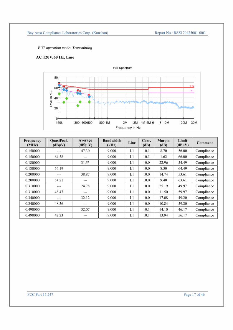
EUT operation mode: Transmitting
AC 120V/60 Hz, Line
0
20
40
60
80
150k 300 400 500 800 1M 2M 3M 4M 5M 6 8 10M 20M 30M
Leve
l in
dBμ
Frequency in Hz
Full Spectrum
QP
AV
Frequency (MHz)
QuasiPeak (dBμV)
Average (dBμV)
Bandwidth (kHz)
LineCorr.(dB)
Margin (dB)
Limit (dBμV)
Comment
0.150000 --- 47.30 9.000 L1 10.1 8.70 56.00 Compliance
0.150000 64.38 --- 9.000 L1 10.1 1.62 66.00 Compliance
0.180000 --- 31.53 9.000 L1 10.0 22.96 54.49 Compliance
0.180000 56.19 --- 9.000 L1 10.0 8.30 64.49 Compliance
0.200000 --- 38.87 9.000 L1 10.0 14.74 53.61 Compliance
0.200000 54.21 --- 9.000 L1 10.0 9.40 63.61 Compliance
0.310000 --- 24.78 9.000 L1 10.0 25.19 49.97 Compliance
0.310000 48.47 --- 9.000 L1 10.0 11.50 59.97 Compliance
0.340000 --- 32.12 9.000 L1 10.0 17.08 49.20 Compliance
0.340000 48.36 --- 9.000 L1 10.0 10.84 59.20 Compliance
0.490000 --- 32.07 9.000 L1 10.1 14.10 46.17 Compliance
0.490000 42.23 --- 9.000 L1 10.1 13.94 56.17 Compliance

Bay Area Compliance Laboratories Corp. (Kunshan) Report No.: RSZ170425001-00C
FCC Part 15.247 Page 18 of 46
AC 120V/60 Hz, Neutral
0
20
40
60
80
150k 300 400 500 800 1M 2M 3M 4M 5M 6 8 10M 20M 30M
Leve
l in
dBμ
Frequency in Hz
Full Spectrum
QP
AV
Note: 1) Corrected Amplitude = Reading + Correction Factor 2) Correction Factor = LISN VDF + Cable Loss + Transient Limiter Attenuation 3) Margin = Limit – Corrected Amplitude
Frequency (MHz)
QuasiPeak (dBμV)
Average (dBμV)
Bandwidth (kHz)
LineCorr.(dB)
Margin (dB)
Limit (dBμV)
Comment
0.160000 58.07 --- 9.000 N 10.1 7.39 65.46 Compliance
0.160000 --- 26.26 9.000 N 10.1 29.20 55.46 Compliance
0.180000 --- 36.90 9.000 N 10.1 17.59 54.49 Compliance
0.180000 60.26 --- 9.000 N 10.1 4.23 64.49 Compliance
0.290000 --- 35.36 9.000 N 10.1 15.16 50.52 Compliance
0.290000 51.78 --- 9.000 N 10.1 8.74 60.52 Compliance
0.320000 --- 38.84 9.000 N 10.1 10.87 49.71 Compliance
0.320000 53.13 --- 9.000 N 10.1 6.58 59.71 Compliance
0.450000 --- 33.61 9.000 N 10.1 13.27 46.88 Compliance
0.450000 43.97 --- 9.000 N 10.1 12.91 56.88 Compliance
0.520000 --- 31.18 9.000 N 10.1 14.82 46.00 Compliance
0.520000 41.90 --- 9.000 N 10.1 14.10 56.00 Compliance
Bay Area Compliance Laboratories Corp. (Kunshan) Report No.: RSZ170425001-00C
FCC Part 15.247 Page 19 of 46
FCC §15.209, §15.205 & §15.247(d) - SPURIOUS EMISSIONS Applicable Standard FCC §15.247 (d); §15.209; §15.205; EUT Setup Below 1 GHz: Above 1GHz:
The radiated emission tests were performed in the 3 meters test site, using the setup accordance with the ANSI C63.10-2013. The specification used was the FCC 15.209, and FCC 15.247 limits.
Bay Area Compliance Laboratories Corp. (Kunshan) Report No.: RSZ170425001-00C
FCC Part 15.247 Page 20 of 46
EMI Test Receiver & Spectrum Analyzer Setup The system was investigated from 30 MHz to 25 GHz. During the radiated emission test, the EMI test receiver & Spectrum Analyzer Setup were set with the following configurations:
Frequency Range RBW Video B/W IF B/W Detector
30 MHz – 1000 MHz 100 kHz 300 kHz 120 kHz QP
Above 1 GHz
1MHz 3 MHz / PK
1MHz 10 Hz Note 1 / Ave.
1MHz 10 Hz Note 2 / Ave.
Note 1: when duty cycle is no less than 98% Note 2: when duty cycle is less than 98% Test Procedure Maximizing procedure was performed on the highest emissions to ensure that the EUT complied with all installation combinations. Data was recorded in Quasi-peak detection mode for frequency range of 30 MHz-1 GHz, peak and Average detection modes for frequencies above 1 GHz. Corrected Amplitude & Margin Calculation The Corrected Amplitude is calculated by adding the Antenna Factor and Cable Loss, and subtracting the Amplifier Gain from the Meter Reading. The basic equation is as follows:
Corrected Amplitude = Meter Reading + Antenna Factor + Cable Loss - Amplifier Gain The “Margin” column of the following data tables indicates the degree of compliance with the applicable limit. For example, a margin of 7dB means the emission is 7dB below the limit. The equation for margin calculation is as follows:
Margin = Limit – Corrected Amplitude Test Results Summary According to the recorded data in following table, the EUT complied with the FCC Title 47, Part 15, Subpart C, section 15.205, 15.209 and 15.247. Refer to CISPR16-4-2:2011 and CISPR 16-4-1:2009, the measured level complies with the limit if
Lm + U(Lm) ≤ Llim + Ucispr In BACL, U(Lm) is less than Ucispr, if Lm is less than Llim, it implies that the EUT complies with the limit.

Bay Area Compliance Laboratories Corp. (Kunshan) Report No.: RSZ170425001-00C
FCC Part 15.247 Page 21 of 46
Test Data
Environmental Conditions
Temperature: 25 ℃
Relative Humidity: 52 %
ATM Pressure: 101.0 kPa
The testing was performed by Layne Li on 2017-06-14. EUT operation mode: Transmitting
30 MHz-25 GHz: For Wi-Fi: 802.11b Mode:
Frequency (MHz)
Receiver Turntable
Degree
Rx Antenna Corrected Factor(dB)
Corrected Amplitude (dBμV/m)
FCC Part 15.247/205/209
Reading (dBμV)
Detector (PK/QP/Ave.)
Height(m)
Polar(H/V)
Limit (dBμV/m)
Margin(dB)
Low Channel (2412 MHz)
47.97 40.46 QP 67 1.8 V -2.52 37.94 40 2.06
2412.00 103.27 PK 355 2.0 H -6.19 97.08 / /
2412.00 97.78 Ave. 355 2.0 H -6.19 91.59 / /
2412.00 112.02 PK 127 1.4 V -6.19 105.83 / /
2412.00 106.97 Ave. 127 1.4 V -6.19 100.78 / /
2321.22 67.9 PK 182 2.3 V -6.42 61.48 74 12.52
2321.22 55.93 Ave. 182 2.3 V -6.42 49.51 54 4.49
2352.54 67.69 PK 151 1.5 V -6.19 61.50 74 12.50
2352.54 54.45 Ave. 151 1.5 V -6.19 48.26 54 5.74
2494.87 67.26 PK 77 1.1 V -5.97 61.29 74 12.71
2494.87 53.82 Ave. 77 1.1 V -5.97 47.85 54 6.15
4824.00 51.87 PK 228 1.9 V 1.6 53.47 74 20.53
4824.00 45.09 Ave. 228 1.9 V 1.6 46.69 54 7.31

Bay Area Compliance Laboratories Corp. (Kunshan) Report No.: RSZ170425001-00C
FCC Part 15.247 Page 22 of 46
Frequency (MHz)
Receiver Turntable
Degree
Rx Antenna Corrected Factor(dB)
Corrected Amplitude (dBμV/m)
FCC Part 15.247/205/209
Reading (dBμV)
Detector (PK/QP/Ave.)
Height(m)
Polar(H/V)
Limit (dBμV/m)
Margin(dB)
Middle Channel (2437 MHz)
47.97 40.6 QP 255 1.9 V -2.52 38.08 40 1.92
2437.00 102.76 PK 152 2.4 H -6.19 96.57 / /
2437.00 98.7 Ave. 152 2.4 H -6.19 92.51 / /
2437.00 111.16 PK 125 1.6 V -6.19 104.97 / /
2437.00 106.27 Ave. 125 1.6 V -6.19 100.08 / /
2337.25 67.73 PK 163 1.6 V -6.42 61.31 74 12.69
2337.25 55.59 Ave. 163 1.6 V -6.42 49.17 54 4.83
2360.66 66.98 PK 15 1.7 V -6.19 60.79 74 13.21
2360.66 54.71 Ave. 15 1.7 V -6.19 48.52 54 5.48
2490.24 66.03 PK 276 1.5 V -5.97 60.06 74 13.94
2490.24 53.84 Ave. 276 1.5 V -5.97 47.87 54 6.13
4874.00 51.38 PK 267 2.3 V 1.83 53.21 74 20.79
4874.00 40.93 Ave. 267 2.3 V 1.83 42.76 54 11.24
High Channel (2462 MHz)
47.97 40.23 QP 162 2.2 V -2.52 37.71 40 2.29
2462.00 100.35 PK 88 1.6 H -5.97 94.38 / /
2462.00 95.96 Ave. 88 1.6 H -5.97 89.99 / /
2462.00 107.74 PK 115 2.4 V -5.97 101.77 / /
2462.00 103.31 Ave. 115 2.4 V -5.97 97.34 / /
2332.92 66.96 PK 29 1.5 V -6.42 60.54 74 13.46
2332.92 53.77 Ave. 29 1.5 V -6.42 47.35 54 6.65
2485.88 66.93 PK 89 1.6 V -5.97 60.96 74 13.04
2485.88 53.9 Ave. 89 1.6 V -5.97 47.93 54 6.07
2499.14 67.75 PK 151 2.3 V -5.97 61.78 74 12.22
2499.14 53.95 Ave. 151 2.3 V -5.97 47.98 54 6.02
4924.00 49.68 PK 175 2.3 V 1.83 51.51 74 22.49
4924.00 35.81 Ave. 175 2.3 V 1.83 37.64 54 16.36

Bay Area Compliance Laboratories Corp. (Kunshan) Report No.: RSZ170425001-00C
FCC Part 15.247 Page 23 of 46
802.11g Mode:
Frequency (MHz)
Receiver Turntable
Degree
Rx Antenna Corrected Factor(dB)
Corrected Amplitude (dBμV/m)
FCC Part 15.247/205/209
Reading (dBμV)
Detector (PK/QP/Ave.)
Height(m)
Polar(H/V)
Limit (dBμV/m)
Margin(dB)
Low Channel (2412 MHz)
47.97 40.4 QP 171 1.9 V -2.52 37.88 40 2.12
2412.00 104.18 PK 118 1.5 H -6.19 97.99 / /
2412.00 93.77 Ave. 118 1.5 H -6.19 87.58 / /
2412.00 112.33 PK 221 1.5 V -6.19 106.14 / /
2412.00 100.6 Ave. 221 1.5 V -6.19 94.41 / /
2357.29 68.25 PK 56 1.5 V -6.19 62.06 74 11.94
2357.29 55.87 Ave. 56 1.5 V -6.19 49.68 54 4.32
2369.31 68.28 PK 160 1.1 V -6.19 62.09 74 11.91
2369.31 54.51 Ave. 160 1.1 V -6.19 48.32 54 5.68
2491.66 66.79 PK 145 1.7 V -5.97 60.82 74 13.18
2491.66 53.86 Ave. 145 1.7 V -5.97 47.89 54 6.11
4824.00 49.17 PK 134 1.7 V 1.6 50.77 74 23.23
4824.00 34.21 Ave. 134 1.7 V 1.6 35.81 54 18.19
Middle Channel(2437 MHz)
47.97 40.33 QP 204 1.3 V -2.52 37.81 40 2.19
2437.00 106.88 PK 51 2.3 H -6.19 100.69 / /
2437.00 94.03 Ave. 51 2.3 H -6.19 87.84 / /
2437.00 110.59 PK 313 1.2 V -6.19 104.40 / /
2437.00 99.9 Ave. 313 1.2 V -6.19 93.71 / /
2348.37 67.36 PK 80 2.3 V -6.42 60.94 74 13.06
2348.37 54.8 Ave. 80 2.3 V -6.42 48.38 54 5.62
2364.36 68.28 PK 130 2.4 V -6.19 62.09 74 11.91
2364.36 54.32 Ave. 130 2.4 V -6.19 48.13 54 5.87
2495.10 66.72 PK 299 1.9 V -5.97 60.75 74 13.25
2495.10 53.92 Ave. 299 1.9 V -5.97 47.95 54 6.05
4874.00 48.8 PK 212 1.3 V 1.83 50.63 74 23.37
4874.00 34.79 Ave. 212 1.3 V 1.83 36.62 54 17.38

Bay Area Compliance Laboratories Corp. (Kunshan) Report No.: RSZ170425001-00C
FCC Part 15.247 Page 24 of 46
Frequency (MHz)
Receiver Turntable
Degree
Rx Antenna Corrected Factor(dB)
Corrected Amplitude (dBμV/m)
FCC Part 15.247/205/209
Reading (dBμV)
Detector (PK/QP/Ave.)
Height(m)
Polar(H/V)
Limit (dBμV/m)
Margin(dB)
High Channel (2462 MHz)
47.97 38.93 QP 231 1.5 V -2.52 36.41 40 3.59
2462.00 102.67 PK 280 2.2 H -5.97 96.70 / /
2462.00 91.39 Ave. 280 2.2 H -5.97 85.42 / /
2462.00 111.22 PK 158 1.1 V -5.97 105.25 / /
2462.00 99.33 Ave. 158 1.1 V -5.97 93.36 / /
2354.68 67.75 PK 152 1.9 V -6.19 61.56 74 12.44
2354.68 54.03 Ave. 152 1.9 V -6.19 47.84 54 6.16
2483.56 69.9 PK 130 2.1 V -5.97 63.93 74 10.07
2483.56 55.94 Ave. 130 2.1 V -5.97 49.97 54 4.03
2489.51 68.23 PK 318 2.5 V -5.97 62.26 74 11.74
2489.51 54.63 Ave. 318 2.5 V -5.97 48.66 54 5.34
4924.00 49.54 PK 308 1.6 V 1.83 51.37 74 22.63
4924.00 35.81 Ave. 308 1.6 V 1.83 37.64 54 16.36

Bay Area Compliance Laboratories Corp. (Kunshan) Report No.: RSZ170425001-00C
FCC Part 15.247 Page 25 of 46
802.11n-HT20 Mode:
Frequency (MHz)
Receiver Turntable
Degree
Rx Antenna Corrected Factor(dB)
Corrected Amplitude (dBμV/m)
FCC Part 15.247/205/209
Reading (dBμV)
Detector (PK/QP/Ave.)
Height(m)
Polar(H/V)
Limit (dBμV/m)
Margin(dB)
Low Channel (2412 MHz)
47.97 40.42 QP 61 2.5 V -2.52 37.90 40 2.10
2412.00 103.6 PK 330 2.4 H -6.19 97.41 / /
2412.00 94.09 Ave. 330 2.4 H -6.19 87.90 / /
2412.00 109.91 PK 319 2.1 V -6.19 103.72 / /
2412.00 98.17 Ave. 319 2.1 V -6.19 91.98 / /
2342.22 67.59 PK 41 1.3 V -6.42 61.17 74 12.83
2342.22 56.2 Ave. 41 1.3 V -6.42 49.78 54 4.22
2359.05 67.92 PK 340 1.3 V -6.19 61.73 74 12.27
2359.05 54.4 Ave. 340 1.3 V -6.19 48.21 54 5.79
2485.17 66.79 PK 151 2.2 V -5.97 60.82 74 13.18
2485.17 53.89 Ave. 151 2.2 V -5.97 47.92 54 6.08
4824.00 48.79 PK 152 2.2 V 1.6 50.39 74 23.61
4824.00 34.21 Ave. 152 2.2 V 1.6 35.81 54 18.19
Middle Channel(2437 MHz)
47.97 40.59 QP 41 1.2 V -2.52 38.07 40 1.93
2437.00 103.54 PK 244 1.2 H -6.19 97.35 / /
2437.00 94.24 Ave. 244 1.2 H -6.19 88.05 / /
2437.00 110.95 PK 193 1.7 V -6.19 104.76 / /
2437.00 99.49 Ave. 193 1.7 V -6.19 93.30 / /
2344.46 67.24 PK 352 2.2 V -6.42 60.82 74 13.18
2344.46 54.57 Ave. 352 2.2 V -6.42 48.15 54 5.85
2375.09 67.96 PK 164 2.1 V -6.19 61.77 74 12.23
2375.09 54.36 Ave. 164 2.1 V -6.19 48.17 54 5.83
2494.70 67.25 PK 55 1.4 V -5.97 61.28 74 12.72
2494.70 53.87 Ave. 55 1.4 V -5.97 47.90 54 6.10
4874.00 48.62 PK 233 2.2 V 1.83 50.45 74 23.55
4874.00 34.79 Ave. 233 2.2 V 1.83 36.62 54 17.38

Bay Area Compliance Laboratories Corp. (Kunshan) Report No.: RSZ170425001-00C
FCC Part 15.247 Page 26 of 46
Frequency (MHz)
Receiver Turntable
Degree
Rx Antenna Corrected Factor(dB)
Corrected Amplitude (dBμV/m)
FCC Part 15.247/205/209
Reading (dBμV)
Detector (PK/QP/Ave.)
Height(m)
Polar(H/V)
Limit (dBμV/m)
Margin(dB)
High Channel (2462 MHz)
47.97 40.25 QP 100 1.1 V -2.52 37.73 40 2.27
2462.00 101.07 PK 275 2.0 H -5.97 95.10 / /
2462.00 90.37 Ave. 275 2.0 H -5.97 84.40 / /
2462.00 108.23 PK 95 1.9 V -5.97 102.26 / /
2462.00 97.79 Ave. 95 1.9 V -5.97 91.82 / /
2381.82 67.25 PK 244 1.6 V -6.19 61.06 74 12.94
2381.82 53.69 Ave. 244 1.6 V -6.19 47.50 54 6.50
2484.29 72.48 PK 10 1.5 V -5.97 66.51 74 7.49
2484.29 54.84 Ave. 10 1.5 V -5.97 48.87 54 5.13
2486.67 68.59 PK 318 1.6 V -5.97 62.62 74 11.38
2486.67 54.32 Ave. 318 1.6 V -5.97 48.35 54 5.65
4924.00 49.16 PK 60 1.0 V 1.83 50.99 74 23.01
4924.00 33.63 Ave. 60 1.0 V 1.83 35.46 54 18.54
Note: Corrected Factor = Antenna factor (RX) + Cable Loss – Amplifier Factor Corrected Amplitude = Corrected Factor + Reading Margin = Limit - Corrected. Amplitude The other spurious emission which is 20dB to the limit was not recorded.

Bay Area Compliance Laboratories Corp. (Kunshan) Report No.: RSZ170425001-00C
FCC Part 15.247 Page 27 of 46
FCC §15.247(a) (2) – 6 dB EMISSION BANDWIDTH Applicable Standard Systems using digital modulation techniques may operate in the 902–928 MHz, 2400–2483.5 MHz, and 5725–5850 MHz bands. The minimum 6 dB bandwidth shall be at least 500 kHz. Test Procedure 1. Check the calibration of the measuring instrument using either an internal calibrator or a known signal
from an external generator. 2. Position the EUT without connection to measurement instrument. Turn on the EUT and connect it to
measurement instrument. Then set it to any one convenient frequency within its operating range. Set a reference level on the measuring instrument equal to the highest peak value.
3. Measure the frequency difference of two frequencies that were attenuated 6 dB from the reference level. Record the frequency difference as the emission bandwidth.
4. Repeat above procedures until all frequencies measured were complete.
Test Data
Environmental Conditions
Temperature: 24~25 ℃
Relative Humidity: 50~54 %
ATM Pressure: 100.0~101.0 kPa
The testing was performed by Chris Wang on 2017-05-14.
EUT operation mode: Transmitting Test Result: Compliance. Please refer to following table and plots.
Signal Analyzer EUT Attenuator
Bay Area Compliance Laboratories Corp. (Kunshan) Report No.: RSZ170425001-00C
FCC Part 15.247 Page 28 of 46
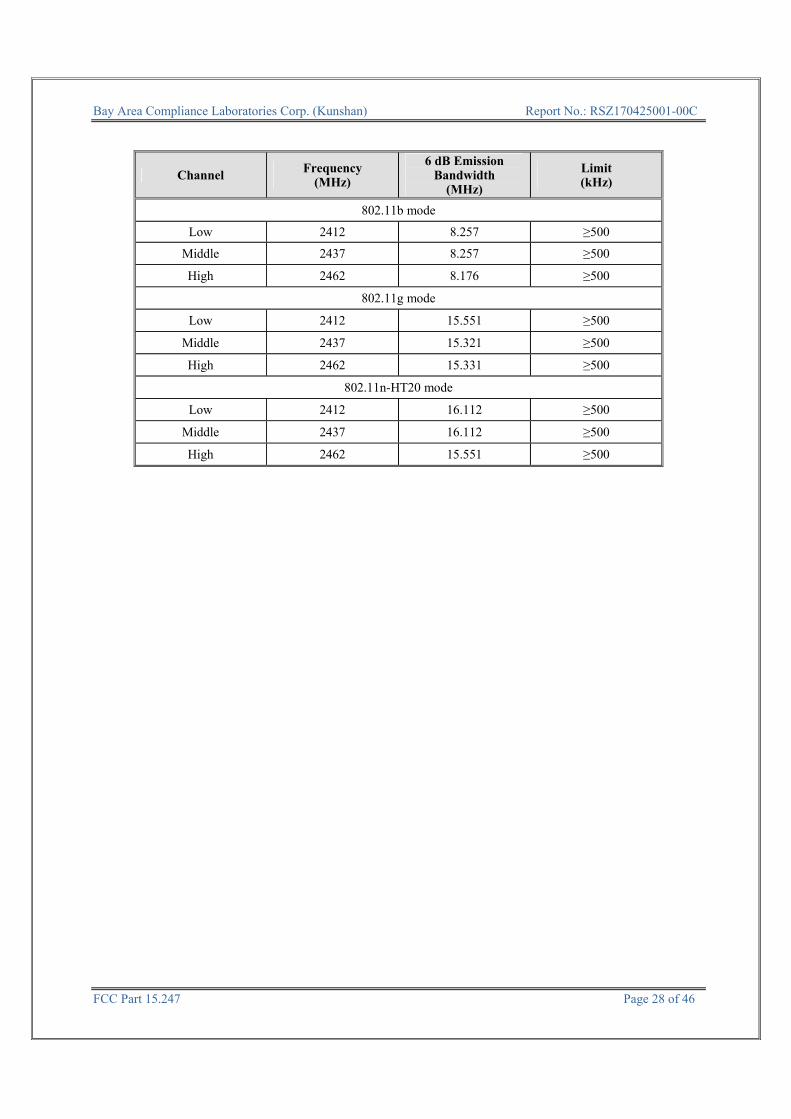
Channel Frequency (MHz)
6 dB Emission Bandwidth
(MHz)
Limit (kHz)
802.11b mode
Low 2412 8.257 ≥500
Middle 2437 8.257 ≥500
High 2462 8.176 ≥500
802.11g mode
Low 2412 15.551 ≥500
Middle 2437 15.321 ≥500
High 2462 15.331 ≥500
802.11n-HT20 mode
Low 2412 16.112 ≥500
Middle 2437 16.112 ≥500
High 2462 15.551 ≥500
Bay Area Compliance Laboratories Corp. (Kunshan) Report No.: RSZ170425001-00C
FCC Part 15.247 Page 29 of 46
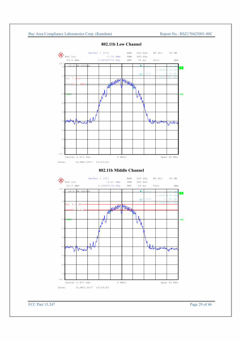
802.11b Low Channel
A
Unit dBm
10.5 dB Offset
RF Att 30 dB
1MA
RBW 100 kHz
SWT 10 ms
VBW 300 kHzRef Lvl
23.5 dBm
Ref Lvl
23.5 dBm
1MAX
Center 2.412 GHz Span 40 MHz4 MHz/
-70
-60
-50
-40
-30
-20
-10
0
10
20
-76.5
23.5
1 1
Marker 1 [T1]
-1.70 dBm
2.40787174 GHz
1 [T1] -1.70 dBm
2.40787174 GHz
1 [T1] -1.16 dB
8.25651303 MHzD1 7 dBm
D2 1 dBm
Date: 14.MAY.2017 15:23:53
802.11b Middle Channel
A
Unit dBm
10.5 dB Offset
RF Att 30 dB
1MA
RBW 100 kHz
SWT 10 ms
VBW 300 kHzRef Lvl
23.5 dBm
Ref Lvl
23.5 dBm
1MAX
Center 2.437 GHz Span 40 MHz4 MHz/
-70
-60
-50
-40
-30
-20
-10
0
10
20
-76.5
23.5
1 1
Marker 1 [T1]
-2.07 dBm
2.43287174 GHz
1 [T1] -2.07 dBm
2.43287174 GHz
1 [T1] -0.96 dB
8.25651303 MHzD1 6.4 dBm
D2 0.4 dBm
Date: 14.MAY.2017 15:24:53

Bay Area Compliance Laboratories Corp. (Kunshan) Report No.: RSZ170425001-00C
FCC Part 15.247 Page 30 of 46
802.11b High Channel
A
Unit dBm
10.5 dB Offset
RF Att 30 dB
1MA
RBW 100 kHz
SWT 10 ms
VBW 300 kHzRef Lvl
23.5 dBm
Ref Lvl
23.5 dBm
Center 2.462 GHz Span 40 MHz4 MHz/
1MAX
-70
-60
-50
-40
-30
-20
-10
0
10
20
-76.5
23.5
11
Marker 1 [T1]
-2.59 dBm
2.45787174 GHz
1 [T1] -2.59 dBm
2.45787174 GHz
1 [T1] 2.24 dB
8.17635271 MHzD1 5.9 dBm
D2 -0.1 dBm
Date: 14.MAY.2017 15:26:52
802.11g Low Channel
A
Unit dBm
10.5 dB Offset
RF Att 30 dB
1MA
RBW 100 kHz
SWT 10 ms
VBW 300 kHzRef Lvl
23.5 dBm
Ref Lvl
23.5 dBm
1MAX
Center 2.412 GHz Span 40 MHz4 MHz/
-70
-60
-50
-40
-30
-20
-10
0
10
20
-76.5
23.5
1 1
Marker 1 [T1]
-3.51 dBm
2.40410421 GHz
1 [T1] -3.51 dBm
2.40410421 GHz
1 [T1] -1.48 dB
15.55110220 MHz
D1 2.9 dBm
D2 -3.1 dBm
Date: 14.MAY.2017 15:19:56

Bay Area Compliance Laboratories Corp. (Kunshan) Report No.: RSZ170425001-00C
FCC Part 15.247 Page 31 of 46
802.11g Middle Channel
A
Unit dBm
10.5 dB Offset
RF Att 30 dB
1MA
RBW 100 kHz
SWT 10 ms
VBW 300 kHzRef Lvl
23.5 dBm
Ref Lvl
23.5 dBm
1MAX
Center 2.437 GHz Span 40 MHz4 MHz/
-70
-60
-50
-40
-30
-20
-10
0
10
20
-76.5
23.5
1 1
Marker 1 [T1]
-4.79 dBm
2.42934469 GHz
1 [T1] -4.79 dBm
2.42934469 GHz
1 [T1] -0.03 dB
15.32064128 MHz
D1 2.8 dBm
D2 -3.2 dBm
Date: 14.MAY.2017 15:21:11
802.11g High Channel
A
Unit dBm
10.5 dB Offset
RF Att 30 dB
1MA
RBW 100 kHz
SWT 10 ms
VBW 300 kHzRef Lvl
23.5 dBm
Ref Lvl
23.5 dBm
1MAX
Center 2.462 GHz Span 40 MHz4 MHz/
-70
-60
-50
-40
-30
-20
-10
0
10
20
-76.5
23.5
1 1
Marker 1 [T1]
-5.12 dBm
2.45434469 GHz
1 [T1] -5.12 dBm
2.45434469 GHz
1 [T1] -0.56 dB
15.33066132 MHz
D1 2.3 dBm
D2 -3.7 dBm
Date: 14.MAY.2017 15:22:27
Bay Area Compliance Laboratories Corp. (Kunshan) Report No.: RSZ170425001-00C
FCC Part 15.247 Page 32 of 46
802.11n-HT20 Low Channel
A
Unit dBm
10.5 dB Offset
RF Att 30 dB
1MA
RBW 100 kHz
SWT 10 ms
VBW 300 kHzRef Lvl
23.5 dBm
Ref Lvl
23.5 dBm
1MAX
Center 2.412 GHz Span 40 MHz4 MHz/
-70
-60
-50
-40
-30
-20
-10
0
10
20
-76.5
23.5
1 1
Marker 1 [T1]
-5.09 dBm
2.40354309 GHz
1 [T1] -5.09 dBm
2.40354309 GHz
1 [T1] -0.56 dB
16.11222445 MHz
D1 1.9 dBm
D2 -4.1 dBm
Date: 14.MAY.2017 15:17:21
802.11n-HT20 Middle Channel
A
Unit dBm
10.5 dB Offset
RF Att 30 dB
1MA
RBW 100 kHz
SWT 10 ms
VBW 300 kHzRef Lvl
23.5 dBm
Ref Lvl
23.5 dBm
Center 2.437 GHz Span 40 MHz4 MHz/
1MAX
-70
-60
-50
-40
-30
-20
-10
0
10
20
-76.5
23.5
1 1
Marker 1 [T1]
-5.37 dBm
2.42854309 GHz
1 [T1] -5.37 dBm
2.42854309 GHz
1 [T1] -0.65 dB
16.11222445 MHz
D1 1.3 dBm
D2 -4.7 dBm
Date: 14.MAY.2017 15:15:06

Bay Area Compliance Laboratories Corp. (Kunshan) Report No.: RSZ170425001-00C
FCC Part 15.247 Page 33 of 46
802.11n-HT20 High Channel
A
Unit dBm
10.5 dB Offset
RF Att 30 dB
1MA
RBW 100 kHz
SWT 10 ms
VBW 300 kHzRef Lvl
23.5 dBm
Ref Lvl
23.5 dBm
1MAX
Center 2.462 GHz Span 40 MHz4 MHz/
-70
-60
-50
-40
-30
-20
-10
0
10
20
-76.5
23.5
1 1
Delta 1 [T1]
-1.24 dB
15.55110220 MHz
1 [T1] -5.92 dBm
2.45410421 GHz
1 [T1] -1.24 dB
15.55110220 MHz
D1 1.1 dBm
D2 -4.9 dBm
Date: 14.MAY.2017 15:18:36

Bay Area Compliance Laboratories Corp. (Kunshan) Report No.: RSZ170425001-00C
FCC Part 15.247 Page 34 of 46
FCC §15.247(b) (3) - MAXIMUM CONDUCTED OUTPUT POWER Applicable Standard According to FCC §15.247(b) (3), for systems using digital modulation in the 902-928 MHz, 2400-2483.5 MHz, and 5725-5850 MHz bands: 1 Watt. As an alternative to a peak power measurement, compliance with the one Watt limit can be based on a measurement of the maximum conducted output power. Maximum Conducted Output Power is defined as the total transmit power delivered to all antennas and antenna elements averaged across all symbols in the signaling alphabet when the transmitter is operating at its maximum power control level. Power must be summed across all antennas and antenna elements. The average must not include any time intervals during which the transmitter is off or is transmitting at a reduced power level. If multiple modes of operation are possible (e.g., alternative modulation methods), the maximum conducted output power is the highest total transmit power occurring in any mode. Test Procedure
1. Place the EUT on a bench and set it in transmitting mode.
2. Connected EUT to the power sensor with a low loss RF cable, Add a correction factor to the power
meter.
3. Set power meter detector to peak and record the valure for Peak Output Power, Set power meter
detector to Average and record the valure for Average Output Power.
4. Repeated 3 until this measurement was finished.
Test Data
Environmental Conditions
Temperature: 24~25 ℃
Relative Humidity: 50~54 %
ATM Pressure: 100.0~101.0 kPa
The testing was performed by Chris Wang on 2017-05-14.
Test Result: Compliance. Please refer to following table and plots.
EUT operation mode: Transmitting
Power Meter EUT Attenuator

Bay Area Compliance Laboratories Corp. (Kunshan) Report No.: RSZ170425001-00C
FCC Part 15.247 Page 35 of 46
Wi-Fi mode
Channel Frequency
(MHz)
Max ConductedPeak Output
Power (dBm)
Limit (dBm)
802.11b
Low 2412 17.48 30
Middle 2437 17.05 30
High 2462 16.52 30
802.11g
Low 2412 21.15 30
Middle 2437 20.52 30
High 2462 20.20 30
802.11n HT20
Low 2412 20.14 30
Middle 2437 19.54 30
High 2462 19.05 30

Bay Area Compliance Laboratories Corp. (Kunshan) Report No.: RSZ170425001-00C
FCC Part 15.247 Page 36 of 46
FCC §15.247(d) – 100 kHz BANDWIDTH OF FREQUENCY BAND EDGE Applicable Standard In any 100 kHz bandwidth outside the frequency band in which the spread spectrum or digitally modulated intentional radiator is operating, the radio frequency power that is produced by the intentional radiator shall be at least 20 dB below that in the 100 kHz bandwidth within the band that contains the highest level of the desired power, based on either an RF conducted or a radiated measurement, provided the transmitter demonstrates compliance with the peak conducted power limits. If the transmitter complies with the conducted power limits based on the use of RMS averaging over a time interval, as permitted under paragraph (b)(3) of this section, the attenuation required under this paragraph shall be 30 dB instead of 20 dB. Attenuation below the general limits specified in §15.209(a) is not required. In addition, radiated emissions which fall in the restricted bands, as defined in §15.205(a), must also comply with the radiated emission limits specified in §15.209(a) (see §15.205(c)). Test Procedure 1. Check the calibration of the measuring instrument using either an internal calibrator or a known signal
from an external generator. 2. Position the EUT without connection to measurement instrument. Turn on the EUT and connect its
antenna terminal to measurement instrument via a low loss cable. Then set it to any one measured frequency within its operating range, and make sure the instrument is operated in its linear range.
3. Set RBW to 100 kHz and VBW of spectrum analyzer to 300 kHz with a convenient frequency span including 100 kHz bandwidth from band edge.
4. Measure the highest amplitude appearing on spectral display and set it as a reference level. Plot the graph with marking the highest point and edge frequency.
5. Repeat above procedures until all measured frequencies were complete.
Test Data
Environmental Conditions
Temperature: 24~25 ℃
Relative Humidity: 50~54 %
ATM Pressure: 100.0~101.0 kPa
The testing was performed by Chris Wang on 2017-05-14.
Test Result: Compliance. Please refer to following table and plots.
EUT operation mode: Transmitting
Signal Analyzer EUT Attenuator

Bay Area Compliance Laboratories Corp. (Kunshan) Report No.: RSZ170425001-00C
FCC Part 15.247 Page 37 of 46
802.11b: Band Edge, Left Side
A
Unit dBm
10.5 dB Offset
RF Att 30 dB
1MA1MAX
Ref Lvl
23.5 dBm
Ref Lvl
23.5 dBm
Center 2.4 GHz Span 50 MHz5 MHz/
RBW 100 kHz
VBW 300 kHz
SWT 12.5 ms
-70
-60
-50
-40
-30
-20
-10
0
10
20
-76.5
23.5
1
Marker 1 [T1]
-37.59 dBm
2.39594188 GHz
1 [T1] -37.59 dBm
2.39594188 GHz
D1 6.5 dBm
D2 -13.5 dBm
Date: 14.MAY.2017 15:28:45
802.11b: Band Edge, Right Side
A
Unit dBm
10.5 dB Offset
RF Att 30 dB
1MA1MAX
RBW 100 kHz
VBW 300 kHz
SWT 17.5 ms
Ref Lvl
23.5 dBm
Ref Lvl
23.5 dBm
7 MHz/Center 2.4835 GHz Span 70 MHz
-70
-60
-50
-40
-30
-20
-10
0
10
20
-76.5
23.5
1
Marker 1 [T1]
-43.96 dBm
2.48497295 GHz
1 [T1] -43.96 dBm
2.48497295 GHz
D1 5.9 dBm
D2 -14.1 dBm
Date: 14.MAY.2017 15:28:00
Bay Area Compliance Laboratories Corp. (Kunshan) Report No.: RSZ170425001-00C
FCC Part 15.247 Page 38 of 46
802.11g: Band Edge, Left Side
A
Unit dBm
10.5 dB Offset
RF Att 30 dB
1MA1MAX
Ref Lvl
23.5 dBm
Ref Lvl
23.5 dBm
Center 2.4 GHz Span 50 MHz5 MHz/
RBW 100 kHz
VBW 300 kHz
SWT 12.5 ms
-70
-60
-50
-40
-30
-20
-10
0
10
20
-76.5
23.5
1
Marker 1 [T1]
-29.00 dBm
2.39864729 GHz
1 [T1] -29.00 dBm
2.39864729 GHz
D1 2.9 dBm
D2 -17.1 dBm
Date: 14.MAY.2017 15:29:38
802.11g: Band Edge, Right Side
A
Unit dBm
10.5 dB Offset
RF Att 30 dB
1MA1MAX
Ref Lvl
23.5 dBm
Ref Lvl
23.5 dBm
Center 2.4835 GHz Span 70 MHz7 MHz/
RBW 100 kHz
VBW 300 kHz
SWT 17.5 ms
-70
-60
-50
-40
-30
-20
-10
0
10
20
-76.5
23.5
1
Marker 1 [T1]
-40.96 dBm
2.48413126 GHz
1 [T1] -40.96 dBm
2.48413126 GHz
D1 2 dBm
D2 -18 dBm
Date: 14.MAY.2017 15:30:24
Bay Area Compliance Laboratories Corp. (Kunshan) Report No.: RSZ170425001-00C
FCC Part 15.247 Page 39 of 46
802.11n-HT20: Band Edge, Left Side
A
Unit dBm
10.5 dB Offset
RF Att 30 dB
1MA1MAX
Ref Lvl
23.5 dBm
Ref Lvl
23.5 dBm
Center 2.4 GHz Span 50 MHz5 MHz/
RBW 100 kHz
VBW 300 kHz
SWT 12.5 ms
-70
-60
-50
-40
-30
-20
-10
0
10
20
-76.5
23.5
1
Marker 1 [T1]
-30.98 dBm
2.39884770 GHz
1 [T1] -30.98 dBm
2.39884770 GHz
D1 1.9 dBm
D2 -18.1 dBm
Date: 14.MAY.2017 15:31:15
802.11n-HT20: Band Edge, Right Side
A
Unit dBm
10.5 dB Offset
RF Att 30 dB
1MA1MAX
Ref Lvl
23.5 dBm
Ref Lvl
23.5 dBm
Center 2.4835 GHz Span 70 MHz7 MHz/
RBW 100 kHz
VBW 300 kHz
SWT 17.5 ms
-70
-60
-50
-40
-30
-20
-10
0
10
20
-76.5
23.5
1
Marker 1 [T1]
-41.88 dBm
2.48357014 GHz
1 [T1] -41.88 dBm
2.48357014 GHz
D1 1.1 dBm
D2 -18.9 dBm
Date: 14.MAY.2017 15:32:10

Bay Area Compliance Laboratories Corp. (Kunshan) Report No.: RSZ170425001-00C
FCC Part 15.247 Page 40 of 46
FCC §15.247(e) - POWER SPECTRAL DENSITY Applicable Standard For digitally modulated systems, the power spectral density conducted from the intentional radiator to the antenna shall not be greater than 8 dBm in any 3 kHz band during any time interval of continuous transmission. This power spectral density shall be determined in accordance with the provisions of paragraph (b) of this section. The same method of determining the conducted output power shall be used to determine the power spectral density. Test Procedure 1. Use this procedure when the maximum peak conducted output power in the fundamental emission is
used to demonstrate compliance. 2. Set the RBW to: 3kHz≤ RBW≤100 kHz. 3. Set the VBW ≥ 3×RBW. 4. Set the span to 1.5 times the DTS bandwidth. 5. Detector = peak. 6. Sweep time = auto couple. 7. Trace mode = max hold. 8. Allow trace to fully stabilize. 9. Use the peak marker function to determine the maximum amplitude level within the RBW. 10. If measured value exceeds limit, reduce RBW (no less than 3 kHz) and repeat.
Test Data
Environmental Conditions
Temperature: 24~25 ℃
Relative Humidity: 50~54 %
ATM Pressure: 100.0~101.0 kPa
The testing was performed by Chris Wang on 2017-05-14.
Test Result: Compliance. Please refer to following table and plots. EUT operation mode: Transmitting
Signal Analyzer EUT Attenuator
Bay Area Compliance Laboratories Corp. (Kunshan) Report No.: RSZ170425001-00C
FCC Part 15.247 Page 41 of 46
Channel Frequency (MHz)
PSD (dBm/3kHz)
Limit (dBm/3kHz)
802.11b mode
Low 2412 -8.50 ≤8
Middle 2437 -8.70 ≤8
High 2462 -9.58 ≤8
802.11g mode
Low 2412 -11.44 ≤8
Middle 2437 -11.28 ≤8
High 2462 -12.85 ≤8
802.11n-HT20 mode
Low 2412 -12.51 ≤8
Middle 2437 -13.00 ≤8
High 2462 -13.53 ≤8
Bay Area Compliance Laboratories Corp. (Kunshan) Report No.: RSZ170425001-00C
FCC Part 15.247 Page 42 of 46
Power Spectral Density, 802.11b Low Channel
A
Unit dBm
10.5 dB Offset
RF Att 30 dB
Ref Lvl
17.5 dBm
Ref Lvl
17.5 dBm
1MA
Center 2.412 GHz Span 12.4 MHz1.24 MHz/
RBW 3 kHz
VBW 10 kHz
SWT 3.5 s
1MAX
-70
-60
-50
-40
-30
-20
-10
0
10
-82.5
17.5
1
Marker 1 [T1]
-8.50 dBm
2.41275792 GHz
1 [T1] -8.50 dBm
2.41275792 GHz
Date: 14.MAY.2017 15:38:39
Power Spectral Density, 802.11b Middle Channel
A
Unit dBm
10.5 dB Offset
RF Att 30 dB
Ref Lvl
17.5 dBm
Ref Lvl
17.5 dBm
1MA
RBW 3 kHz
VBW 10 kHz
SWT 3.5 s
1MAX
Center 2.437 GHz Span 12.4 MHz1.24 MHz/
-70
-60
-50
-40
-30
-20
-10
0
10
-82.5
17.5
1
Marker 1 [T1]
-8.70 dBm
2.43770822 GHz
1 [T1] -8.70 dBm
2.43770822 GHz
Date: 14.MAY.2017 15:39:21

Bay Area Compliance Laboratories Corp. (Kunshan) Report No.: RSZ170425001-00C
FCC Part 15.247 Page 43 of 46
Power Spectral Density, 802.11b High Channel
A
Unit dBm
10.5 dB Offset
RF Att 30 dB
Ref Lvl
17.5 dBm
Ref Lvl
17.5 dBm
1MA
RBW 3 kHz
VBW 10 kHz
SWT 3.5 s
1MAX
Center 2.462 GHz Span 12.4 MHz1.24 MHz/
-70
-60
-50
-40
-30
-20
-10
0
10
-82.5
17.5
1
Marker 1 [T1]
-9.58 dBm
2.46131663 GHz
1 [T1] -9.58 dBm
2.46131663 GHz
Date: 14.MAY.2017 15:39:48
Power Spectral Density, 802.11g Low Channel
A
Unit dBm
10.5 dB Offset
RF Att 30 dB
Ref Lvl
17.5 dBm
Ref Lvl
17.5 dBm
1MAX 1MA
Center 2.412 GHz Span 23.4 MHz2.34 MHz/
RBW 3 kHz
VBW 10 kHz
SWT 6.6 s
-70
-60
-50
-40
-30
-20
-10
0
10
-82.5
17.5
1
Marker 1 [T1]
-11.44 dBm
2.41169519 GHz
1 [T1] -11.44 dBm
2.41169519 GHz
Date: 14.MAY.2017 15:35:42
Bay Area Compliance Laboratories Corp. (Kunshan) Report No.: RSZ170425001-00C
FCC Part 15.247 Page 44 of 46
Power Spectral Density, 802.11g Middle Channel
A
Unit dBm
10.5 dB Offset
RF Att 30 dB
Ref Lvl
17.5 dBm
Ref Lvl
17.5 dBm
1MAX 1MA
RBW 3 kHz
VBW 10 kHz
SWT 6.6 s
Center 2.437 GHz Span 23.4 MHz2.34 MHz/
-70
-60
-50
-40
-30
-20
-10
0
10
-82.5
17.5
1
Marker 1 [T1]
-11.28 dBm
2.43603868 GHz
1 [T1] -11.28 dBm
2.43603868 GHz
Date: 14.MAY.2017 15:36:09
Power Spectral Density, 802.11g High Channel
A
Unit dBm
10.5 dB Offset
RF Att 30 dB
Ref Lvl
17.5 dBm
Ref Lvl
17.5 dBm
1MAX 1MA
RBW 3 kHz
VBW 10 kHz
SWT 6.6 s
Center 2.462 GHz Span 23.4 MHz2.34 MHz/
-70
-60
-50
-40
-30
-20
-10
0
10
-82.5
17.5
1
Marker 1 [T1]
-12.85 dBm
2.46071042 GHz
1 [T1] -12.85 dBm
2.46071042 GHz
Date: 14.MAY.2017 15:36:52

Bay Area Compliance Laboratories Corp. (Kunshan) Report No.: RSZ170425001-00C
FCC Part 15.247 Page 45 of 46
Power Spectral Density, 802.11n-HT20 Low Channel
A
Unit dBm
10.5 dB Offset
RF Att 30 dBRBW 3 kHz
VBW 10 kHz
SWT 6.8 s
Ref Lvl
17.5 dBm
Ref Lvl
17.5 dBm
1MAX 1MA
Center 2.412 GHz Span 24.2 MHz2.42 MHz/
-70
-60
-50
-40
-30
-20
-10
0
10
-82.5
17.5
1
Marker 1 [T1]
-12.51 dBm
2.41226673 GHz
1 [T1] -12.51 dBm
2.41226673 GHz
Date: 14.MAY.2017 15:34:54
Power Spectral Density, 802.11n-HT20 Middle Channel
A
Unit dBm
10.5 dB Offset
RF Att 30 dBRBW 3 kHz
VBW 10 kHz
SWT 6.8 s
Ref Lvl
17.5 dBm
Ref Lvl
17.5 dBm
1MAX 1MA
Center 2.437 GHz Span 24.2 MHz2.42 MHz/
-70
-60
-50
-40
-30
-20
-10
0
10
-82.5
17.5
1
Marker 1 [T1]
-13.00 dBm
2.43610281 GHz
1 [T1] -13.00 dBm
2.43610281 GHz
Date: 14.MAY.2017 15:34:26
Bay Area Compliance Laboratories Corp. (Kunshan) Report No.: RSZ170425001-00C
FCC Part 15.247 Page 46 of 46
Power Spectral Density, 802.11n-HT20 High Channel
A
Unit dBm
10.5 dB Offset
RF Att 30 dBRBW 3 kHz
VBW 10 kHz
SWT 6.8 s
Ref Lvl
17.5 dBm
Ref Lvl
17.5 dBm
2.42 MHz/Center 2.462 GHz Span 24.2 MHz
1MAX 1MA
-70
-60
-50
-40
-30
-20
-10
0
10
-82.5
17.5
1
Marker 1 [T1]
-13.53 dBm
2.46357615 GHz
1 [T1] -13.53 dBm
2.46357615 GHz
Date: 14.MAY.2017 15:33:50
***** END OF REPORT *****