fccid.io · applicant . ctc advanced gmbh . untertuerkheimer strasse 6 – 10 : 66117 saarbruecken...
TRANSCRIPT
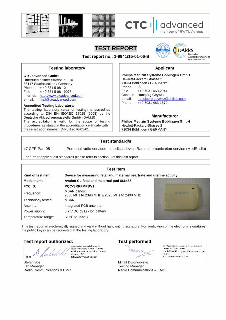
TEST REPORT Test report no.: 1-9941/15-01-06-B
Testing laboratory Applicant
CTC advanced GmbH Untertuerkheimer Strasse 6 – 10 66117 Saarbruecken / Germany Phone: + 49 681 5 98 - 0 Fax: + 49 681 5 98 - 9075 Internet: http://www.ctcadvanced.com e-mail: [email protected]
Accredited Testing Laboratory: The testing laboratory (area of testing) is accredited according to DIN EN ISO/IEC 17025 (2005) by the Deutsche Akkreditierungsstelle GmbH (DAkkS) The accreditation is valid for the scope of testing procedures as stated in the accreditation certificate with the registration number: D-PL-12076-01-01
Philips Medizin Systeme Böblingen GmbH Hewlett-Packard-Strasse 2 71034 Böblingen / GERMANY Phone: -/- Fax: +49 7031 463-2944 Contact: Hansjörg Geywitz e-mail: [email protected] Phone: +49 7031 463-1879
Manufacturer Philips Medizin Systeme Böblingen GmbH Hewlett-Packard-Strasse 2 71034 Böblingen / GERMANY
Test standard/s
47 CFR Part 95 Personal radio services – medical device Radiocommunication service (MedRadio)
For further applied test standards please refer to section 3 of this test report.
Test Item Kind of test item: Device for measuring fetal and maternal heartrate and uterine activity Model name: Avalon CL fetal and maternal pod 866488
FCC ID: PQC-SRRFMPBV1
Frequency: MBAN bands: 2360 MHz to 2390 MHz & 2390 MHz to 2400 MHz
Technology tested: MBAN Antenna: Integrated PCB antenna Power supply: 3.7 V DC by Li - Ion battery
Temperature range: -20°C to +55°C This test report is electronically signed and valid without handwriting signature. For verification of the electronic signatures, the public keys can be requested at the testing laboratory.
Test report authorized: Test performed:
p.o.
Stefan Bös Mihail Dorongovskij Lab Manager Testing Manager Radio Communications & EMC Radio Communications & EMC
Test report no.: 1-9941/15-01-06-B
Page 2 of 79
1 Table of contents
1 Table of contents ............................................................................................................................................ 2
2 General information ....................................................................................................................................... 3
2.1 Notes and disclaimer .......................................................................................................................... 3 2.2 Application details ............................................................................................................................... 3
3 Test standard/s and references .................................................................................................................... 3
4 Test environment ............................................................................................................................................ 4
5 Test item .......................................................................................................................................................... 4
5.1 General description ............................................................................................................................. 4 5.2 Additional information ........................................................................................................................ 4
6 Test laboratories sub-contracted ................................................................................................................. 4
7 Description of the test setup ......................................................................................................................... 5
7.1 Shielded semi anechoic chamber ...................................................................................................... 6 7.2 Shielded fully anechoic chamber ...................................................................................................... 7 7.3 Radiated measurements > 18 GHz ..................................................................................................... 8 7.4 Conducted measurements C.BER system ........................................................................................ 9 7.5 Test setup for the timing behavior................................................................................................... 10 7.6 Shielded fully anechoic chamber .................................................................................................... 11
8 Sequence of testing ..................................................................................................................................... 12
8.1 Sequence of testing radiated spurious 9 kHz to 30 MHz ............................................................... 12 8.2 Sequence of testing radiated spurious 30 MHz to 1 GHz .............................................................. 13 8.3 Sequence of testing radiated spurious 1 GHz to 18 GHz .............................................................. 14 8.4 Sequence of testing radiated spurious above 18 GHz .................................................................. 15
9 Measurement uncertainty ............................................................................................................................ 16
10 Summary of measurement results .......................................................................................................... 17
11 Additional comments ............................................................................................................................... 18
Project Note ........................................................................................................................................................... 19 Subject: MBAN System Description for FCC Approval ......................................................................................... 19
Affected Products: ................................................................................................................................................. 19
12 Measurement results ................................................................................................................................ 21
12.1 Frequency stability ........................................................................................................................ 21 12.2 Emission bandwidth ...................................................................................................................... 27 12.3 Maximum transmit power .............................................................................................................. 31 12.4 Band edge measurement .............................................................................................................. 41 12.5 Transmitter unwanted radiation (radiated) .................................................................................. 43 12.6 Receiver unwanted radiation (radiated) ...................................................................................... 67 12.7 Connection interrupt test (body-worn sensor) ........................................................................... 72
13 Observations ............................................................................................................................................. 77 Annex A Glossary .......................................................................................................................................... 78
Annex B Document history .......................................................................................................................... 79
Annex C Accreditation Certificate ............................................................................................................... 79
Test report no.: 1-9941/15-01-06-B
Page 3 of 79
2 General information 2.1 Notes and disclaimer The test results of this test report relate exclusively to the test item specified in this test report. CTC advanced GmbH does not assume responsibility for any conclusions and generalizations drawn from the test results with regard to other specimens or samples of the type of the equipment represented by the test item. The test report may only be reproduced or published in full. Reproduction or publication of extracts from the report requires the prior written approval of CTC advanced GmbH. The testing service provided by CTC advanced GmbH has been rendered under the current "General Terms and Conditions for CTC advanced GmbH". CTC advanced GmbH will not be liable for any loss or damage resulting from false, inaccurate, inappropriate or incomplete product information provided by the customer. Under no circumstances does the CTC advanced GmbH test report include any endorsement or warranty regarding the functionality, quality or performance of any other product or service provided. Under no circumstances does the CTC advanced GmbH test report include or imply any product or service warranties from CTC advanced GmbH, including, without limitation, any implied warranties of merchantability, fitness for purpose, or non-infringement, all of which are expressly disclaimed by CTC advanced GmbH. All rights and remedies regarding vendor’s products and services for which CTC advanced GmbH has prepared this test report shall be provided by the party offering such products or services and not by CTC advanced GmbH. In no case this test report can be considered as a Letter of Approval. This test report is electronically signed and valid without handwritten signature. For verification of the electronic signatures, the public keys can be requested at the testing laboratory. This test report replaces the test report with the number 1-9941/15-01-06-A and dated 2017-08-16 2.2 Application details Date of receipt of order: 2016-08-26 Date of receipt of test item: 2016-08-29 Start of test: 2016-08-29 End of test: 2017-06-08 Person(s) present during the test: -/-
3 Test standard/s and references Test standard Date Description
47 CFR Part 95 May-14-2009 Personal radio services – medical device Radiocommunication service (MedRadio)
Guidance Version Description
ANSI C63.4-2014 -/- American national standard for methods of measurement of radio-noise emissions from low-voltage electrical and electronic equipment in the range of 9 kHz to 40 GHz
KDB 550599 D01 v01 June-17-2016 Medical body area network (MBAN) measurement procedures

Test report no.: 1-9941/15-01-06-B
Page 4 of 79
4 Test environment
Temperature : Tnom Tmax Tmin
+22 °C during room temperature tests +55 °C during high temperature tests 0 °C during low temperature tests
Relative humidity content : 55 % Barometric pressure : not relevant for this kind of testing
Power supply : Vnom Vmax Vmin
3.7 V DC by Li - Ion battery 4.1 V 2.8 V
5 Test item 5.1 General description Kind of test item : Device for measuring fetal and maternal heartrate and uterine activity Type identification : Avalon CL fetal and maternal pod 866488
S/N serial number : Radiated unit: XW62500238 Conducted unit: XW62500203
HW hardware status : 1 SW software status : D.00.58
Frequency band : MBAN bands: 2360 MHz to 2390 MHz & 2390 MHz to 2400 MHz (lowest channel 2363 MHz, highest channel 2397 MHz)
Type of radio transmission : Use of frequency spectrum : modulated carrier, DSSS
Type of modulation : OQPSK Number of channels : 15 Antenna : Integrated PCB antenna Power supply : 3.7 V DC by Li - Ion battery Temperature range : -20°C to +55°C
5.2 Additional information The content of the following annexes is defined in the QA. It may be that not all of the listed annexes are necessary for this report, thus some values in between may be missing.
Test setup- and EUT-photos are included in test report: 1-9941/15-01-01_AnnexA 1-9941/15-01-01_AnnexB (Photos provided by customer) 1-9941/15-01-01_AnnexD 6 Test laboratories sub-contracted None
Test report no.: 1-9941/15-01-06-B
Page 5 of 79
7 Description of the test setup Typically, the calibrations of the test apparatus are commissioned to and performed by an accredited calibration laboratory. The calibration intervals are determined in accordance with the DIN EN ISO/IEC 17025. In addition to the external calibrations, the laboratory executes comparison measurements with other calibrated test systems or effective verifications. Weekly chamber inspections and range calibrations are performed. Where possible, RF generating and signaling equipment as well as measuring receivers and analyzers are connected to an external high-precision 10 MHz reference (GPS-based or rubidium frequency standard). In order to simplify the identification of the equipment used at some special tests, some items of test equipment and ancillaries can be provided with an identifier or number in the equipment list below (Lab/Item). Agenda: Kind of Calibration
k calibration / calibrated EK limited calibration ne not required (k, ev, izw, zw not required) zw cyclical maintenance (external cyclical
maintenance) ev periodic self verification izw internal cyclical maintenance Ve long-term stability recognized g blocked for accredited testing vlkI! Attention: extended calibration interval NK! Attention: not calibrated *) next calibration ordered / currently in progress
Test report no.: 1-9941/15-01-06-B
Page 6 of 79
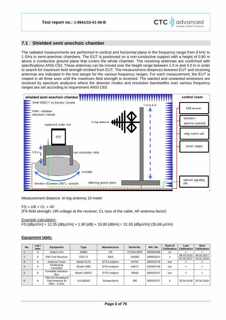
7.1 Shielded semi anechoic chamber The radiated measurements are performed in vertical and horizontal plane in the frequency range from 9 kHz to 1 GHz in semi-anechoic chambers. The EUT is positioned on a non-conductive support with a height of 0.80 m above a conductive ground plane that covers the whole chamber. The receiving antennas are confirmed with specifications ANSI C63. These antennas can be moved over the height range between 1.0 m and 4.0 m in order to search for maximum field strength emitted from EUT. The measurement distances between EUT and receiving antennas are indicated in the test setups for the various frequency ranges. For each measurement, the EUT is rotated in all three axes until the maximum field strength is received. The wanted and unwanted emissions are received by spectrum analyzers where the detector modes and resolution bandwidths over various frequency ranges are set according to requirement ANSI C63.
Measurement distance: tri-log antenna 10 meter FS = UR + CL + AF (FS-field strength; UR-voltage at the receiver; CL-loss of the cable; AF-antenna factor) Example calculation: FS [dBµV/m] = 12.35 [dBµV/m] + 1.90 [dB] + 16.80 [dB/m] = 31.05 [dBµV/m] (35.69 µV/m) Equipment table:
No. Lab / Item Equipment Type Manufacturer Serial No. INV. No. Kind of
Calibration Last
Calibration Next
Calibration 1 A Switch-Unit 3488A HP 2719A14505 300000368 ev -/- -/-
2 A EMI Test Receiver ESCI 3 R&S 100083 300003312 k 08.03.2016 08.03.2017 01.02.2017 31.01.2018
3 A Antenna Tower Model 2175 ETS-Lindgren 64762 300003745 izw -/- -/-
4 A Positioning Controller Model 2090 ETS-Lindgren 64672 300003746 izw -/- -/-
5 A Turntable Interface-Box Model 105637 ETS-Lindgren 44583 300003747 izw -/- -/-
6 A TRILOG Broadband
Test-Antenna 30 MHz - 3 GHz
VULB9163 Schwarzbeck 295 300003787 k 25.04.2016 25.04.2018
Test report no.: 1-9941/15-01-06-B
Page 7 of 79
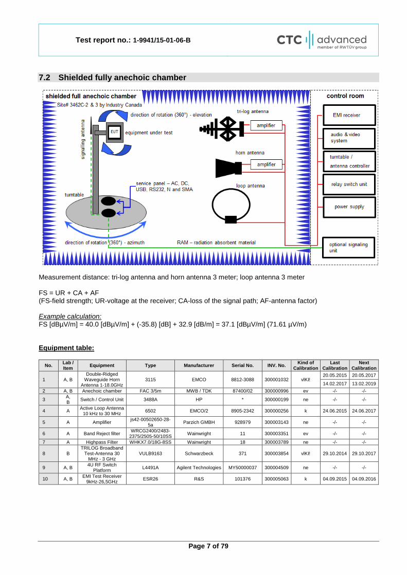
7.2 Shielded fully anechoic chamber
Measurement distance: tri-log antenna and horn antenna 3 meter; loop antenna 3 meter FS = UR + CA + AF (FS-field strength; UR-voltage at the receiver; CA-loss of the signal path; AF-antenna factor) Example calculation: FS [dBµV/m] = 40.0 [dBµV/m] + (-35.8) [dB] + 32.9 [dB/m] = 37.1 [dBµV/m] (71.61 µV/m) Equipment table:
No. Lab / Item Equipment Type Manufacturer Serial No. INV. No. Kind of
Calibration Last
Calibration Next
Calibration
1 A, B Double-Ridged
Waveguide Horn Antenna 1-18.0GHz
3115 EMCO 8812-3088 300001032 vlKI! 20.05.2015 20.05.2017
14.02.2017 13.02.2019 2 A, B Anechoic chamber FAC 3/5m MWB / TDK 87400/02 300000996 ev -/- -/-
3 A, B Switch / Control Unit 3488A HP * 300000199 ne -/- -/-
4 A Active Loop Antenna 10 kHz to 30 MHz 6502 EMCO/2 8905-2342 300000256 k 24.06.2015 24.06.2017
5 A Amplifier js42-00502650-28-5a Parzich GMBH 928979 300003143 ne -/- -/-
6 A Band Reject filter WRCG2400/2483-2375/2505-50/10SS Wainwright 11 300003351 ev -/- -/-
7 A Highpass Filter WHKX7.0/18G-8SS Wainwright 18 300003789 ne -/- -/-
8 B TRILOG Broadband
Test-Antenna 30 MHz - 3 GHz
VULB9163 Schwarzbeck 371 300003854 vlKI! 29.10.2014 29.10.2017
9 A, B 4U RF Switch Platform L4491A Agilent Technologies MY50000037 300004509 ne -/- -/-
10 A, B EMI Test Receiver 9kHz-26,5GHz ESR26 R&S 101376 300005063 k 04.09.2015 04.09.2016

Test report no.: 1-9941/15-01-06-B
Page 8 of 79
7.3 Radiated measurements > 18 GHz
Measurement distance: horn antenna 50 cm FS = UR + CA + AF (FS-field strength; UR-voltage at the receiver; CA-loss signal path & distance correction; AF-antenna factor) Example calculation: FS [dBµV/m] = 40.0 [dBµV/m] + (-60.1) [dB] + 36.74 [dB/m] = 16.64 [dBµV/m] (6.79 µV/m) Equipment table:
No. Lab / Item Equipment Type Manufacturer Serial No. INV. No. Kind of
Calibration Last
Calibration Next
Calibration
1 A Amplifier 2-40 GHz JS32-02004000-57-5P MITEQ 1777200 300004541 ev -/- -/-
2 A RF-Cable ST18/SMAm/SMAm/48 Huber & Suhner Batch no.
600918 400001182 ev -/- -/-
3 A RF-Cable ST18/SMAm/SMm/48 Huber & Suhner Batch no.
127377 400001183 ev -/- -/-
4 A DC-Blocker 0.1-40 GHz 8141A Inmet Batch no.
127377 400001185 ev -/- -/-
5 A Std. Gain Horn
Antenna 18.0 to 26.5 GHz
638 Narda -/- 300000486 k 10.09.2015 10.09.2017
6 A Signal Analyzer 40 GHz FSV40 R&S 101042 300004517 k 21.01.2016 21.01.2017
25.01.2017 24.01.2018

Test report no.: 1-9941/15-01-06-B
Page 9 of 79
7.4 Conducted measurements C.BER system
OP = AV + CA (OP-output power; AV-analyzer value; CA-loss signal path) Example calculation: OP [dBm] = 6.0 [dBm] + 11.7 [dB] = 17.7 [dBm] (58.88 mW) Equipment table:
No. Lab / Item Equipment Type Manufacturer Serial No. INV. No. Kind of
Calibration Last
Calibration Next
Calibration 1 A, B Switch / Control Unit 3488A HP -/- 300001691 ne -/- -/-
2 A, B Power Supply DC NGPE 40/40 R&S 388 400000078 vlKI! 22.01.2015 22.01.2017 31.01.2017 30.01.2020
3 A, B Signal Analyzer
20Hz-26,5GHz-150 to + 30 DBM
FSIQ26 R&S 835540/018 300002681 k 28.01.2016 28.01.2018
4 A, B
Frequency Standard (Rubidium Frequency Standard)
MFS (Rubidium) R&S (Datum) 002 300002681 Ve 29.01.2015 29.01.2017
27.01.2017 26.01.2019
5 A, Directional Coupler 101020010 Krytar 70215 300002840 ev -/- -/- 6 A, B DC-Blocker 8143 Inmet Corp. none 300002842 ne -/- -/- 7 A, B Powersplitter 6005-3 Inmet Corp. none 300002841 ev -/- -/- 8 A, B USB/GPIB interface 82357B Agilent Technologies MY52103346 300004390 ne -/- -/- 9 A, B Messplatzrechner Tecline F+W 102585 300003580 ne -/- -/-
10 A, B RF-Cable ST18/SMAm/SMAm/72 Huber & Suhner Batch no.
605505 400001187 ev -/- -/-
11 A, B RF-Cable Sucoflex 104 Huber & Suhner 147636/4 400001188 ev -/- -/-
12 A, B RF-Cable ST18/SMAm/SMAm/48 Huber & Suhner Batch no.
699866 400001189 ev -/- -/-
13 A, B RF-Cable ST18/SMAm/SMAm/48 Huber & Suhner Batch no. 14844 400001190 ev -/- -/-
14 B Temperature Test Chamber VT 4002 Heraeus Voetsch 5856604682001
0 300003019 ev 03.09.2015 03.09.2017
Test report no.: 1-9941/15-01-06-B
Page 10 of 79
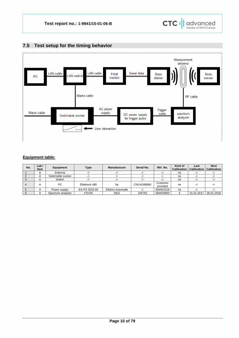
7.5 Test setup for the timing behavior
Equipment table:
No. Lab / Item Equipment Type Manufacturer Serial No. INV. No. Kind of
Calibration Last
Calibration Next
Calibration 1 A Antenna -/- -/- -/- -/- ne -/- -/- 2 A Switchable socket -/- -/- -/- -/- ne -/- -/- 3 A Switch -/- -/- -/- -/- ne -/- -/-
4 A PC Elitebock 480 hp CNU416B860 Customer provided ne -/- -/-
5 A Power supply EA-PS 3032-65 Elektro Automatik -/- 300002318 ne -/- -/- 6 A Spectrum analyser FSV30 R&S 100763 300003950 k 31.01.2017 30.01.2018
Test report no.: 1-9941/15-01-06-B
Page 11 of 79
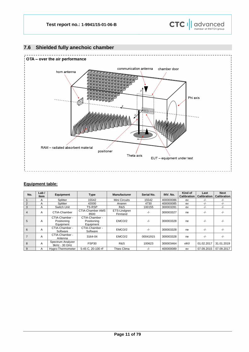
7.6 Shielded fully anechoic chamber
Equipment table:
No. Lab / Item Equipment Type Manufacturer Serial No. INV. No. Kind of
Calibration Last
Calibration Next
Calibration 1 A Splitter 15542 Mini Circuits 15542 400000086 ev -/- -/- 2 A Splitter 42000 Anaren 4730 400000085 ev -/- -/- 3 A Switch Unit TS-RSP R&S 100155 300003281 ev -/- -/-
4 A CTIA-Chamber CTIA-Chamber AMS 8500
ETS-Lindgren Finnland -/- 300003327 ne -/- -/-
5 A CTIA-Chamber -
Positioning Equipment
CTIA-Chamber - Positioning Equipment
EMCO/2 -/- 300003328 ne -/- -/-
6 A CTIA-Chamber - Software
CTIA-Chamber - Software EMCO/2 -/- 300003328 ne -/- -/-
7 A CTIA-Chamber - Antenna 3164-04 EMCO/2 00041915 300003328 ne -/- -/-
8 A Spectrum Analyzer 9kHz - 30 GHz FSP30 R&S 100623 300003464 vlKI! 01.02.2017 31.01.2019
9 A Hygro-Thermometer 5-45 C, 20-100 rF Thies Clima -/- 400000089 ev 07.09.2015 07.09.2017
Test report no.: 1-9941/15-01-06-B
Page 12 of 79
8 Sequence of testing 8.1 Sequence of testing radiated spurious 9 kHz to 30 MHz Setup
• The equipment is set up to simulate normal operation mode as described in the user manual or defined by the manufacturer.
• If the EUT is a tabletop system, a 2-axis positioner with 1.5 m height is used. • If the EUT is a floor standing device, it is placed directly on the turn table. • Auxiliary equipment and cables are positioned to simulate normal operation conditions as described in
ANSI C 63.4. • The AC power port of the EUT (if available) is connected to a power outlet below the turntable. • Measurement distance is 3 m (see ANSI C 63.4) – see test details. • EUT is set into operation.
Premeasurement
• The turntable rotates from 0° to 315° using 45° steps. • The antenna height is 1.5 m. • At each turntable position the analyzer sweeps with positive-peak detector to find the maximum of all
emissions. Final measurement
• Identified emissions during the premeasurement are maximized by the software by rotating the turntable from 0° to 360°. In case of the 2-axis positioner is used the elevation axis is also rotated from 0° to 360°.
• The final measurement is done in the position (turntable and elevation) causing the highest emissions with quasi-peak (as described in ANSI C 63.4).
• Final levels, frequency, measuring time, bandwidth, turntable position, correction factor, margin to the limit and limit will be recorded. A plot with the graph of the premeasurement and the limit is stored.
Test report no.: 1-9941/15-01-06-B
Page 13 of 79
8.2 Sequence of testing radiated spurious 30 MHz to 1 GHz Setup
• The equipment is set up to simulate normal operation mode as described in the user manual or defined by the manufacturer.
• If the EUT is a tabletop system, a table with 0.8 m height is used, which is placed on the ground plane. • If the EUT is a floor standing device, it is placed on the ground plane with insulation between both. • Auxiliary equipment and cables are positioned to simulate normal operation conditions as described in
ANSI C 63.4. • The AC power port of the EUT (if available) is connected to a power outlet below the turntable. • Measurement distance is 10 m or 3 m (see ANSI C 63.4) – see test details. • EUT is set into operation.
Premeasurement
• The turntable rotates from 0° to 315° using 45° steps. • The antenna is polarized vertical and horizontal. • The antenna height changes from 1 m to 3 m. • At each turntable position, antenna polarization and height the analyzer sweeps three times in peak to
find the maximum of all emissions. Final measurement
• The final measurement is performed for at least six highest peaks according to the requirements of the ANSI C63.4.
• Based on antenna and turntable positions at which the peak values are measured the software maximize the peaks by changing turntable position ± 45° and antenna height between 1 and 4 m.
• The final measurement is done with quasi-peak detector (as described in ANSI C 63.4). • Final levels, frequency, measuring time, bandwidth, antenna height, antenna polarization, turntable angle,
correction factor, margin to the limit and limit are recorded. A plot with the graph of the premeasurement with marked maximum final results and the limit is stored.
Test report no.: 1-9941/15-01-06-B
Page 14 of 79
8.3 Sequence of testing radiated spurious 1 GHz to 18 GHz Setup
• The equipment is set up to simulate normal operation mode as described in the user manual or defined by the manufacturer.
• If the EUT is a tabletop system, a 2-axis positioner with 1.5 m height is used. • If the EUT is a floor standing device, it is placed directly on the turn table. • Auxiliary equipment and cables are positioned to simulate normal operation conditions as described in
ANSI C 63.4. • The AC power port of the EUT (if available) is connected to a power outlet below the turntable. • Measurement distance is 3 m (see ANSI C 63.4) – see test details. • EUT is set into operation.
Premeasurement
• The turntable rotates from 0° to 315° using 45° steps. • The antenna is polarized vertical and horizontal. • The antenna height is 1.5 m. • At each turntable position and antenna polarization the analyzer sweeps with positive peak detector to
find the maximum of all emissions. Final measurement
• The final measurement is performed for at least six highest peaks according to the requirements of the ANSI C63.4.
• Based on antenna and turntable positions at which the peak values are measured the software maximizes the peaks by rotating the turntable from 0° to 360°. This measurement is repeated for different EUT-table positions (0° to 150° in 30°-steps) and for both antenna polarizations.
• The final measurement is done in the position (turntable, EUT-table and antenna polarization) causing the highest emissions with Peak and RMS detector (as described in ANSI C 63.4).
• Final levels, frequency, measuring time, bandwidth, turntable position, EUT-table position, antenna polarization, correction factor, margin to the limit and limit are recorded. A plot with the graph of the premeasurement with marked maximum final results and the limit is stored.

Test report no.: 1-9941/15-01-06-B
Page 15 of 79
8.4 Sequence of testing radiated spurious above 18 GHz Setup
• The equipment is set up to simulate normal operation mode as described in the user manual or defined by the manufacturer.
• Auxiliary equipment and cables are positioned to simulate normal operation conditions as described in ANSI C 63.4.
• The AC power port of the EUT (if available) is connected to a power outlet. • The measurement distance is as appropriate (e.g. 0.5 m). • The EUT is set into operation.
Premeasurement
• The test antenna is handheld and moved carefully over the EUT to cover the EUT’s whole sphere and different polarizations of the antenna.
Final measurement
• The final measurement is performed at the position and antenna orientation causing the highest emissions with Peak and RMS detector (as described in ANSI C 63.4).
• Final levels, frequency, measuring time, bandwidth, correction factor, margin to the limit and limit are recorded. A plot with the graph of the premeasurement and the limit is stored.
Test report no.: 1-9941/15-01-06-B
Page 16 of 79
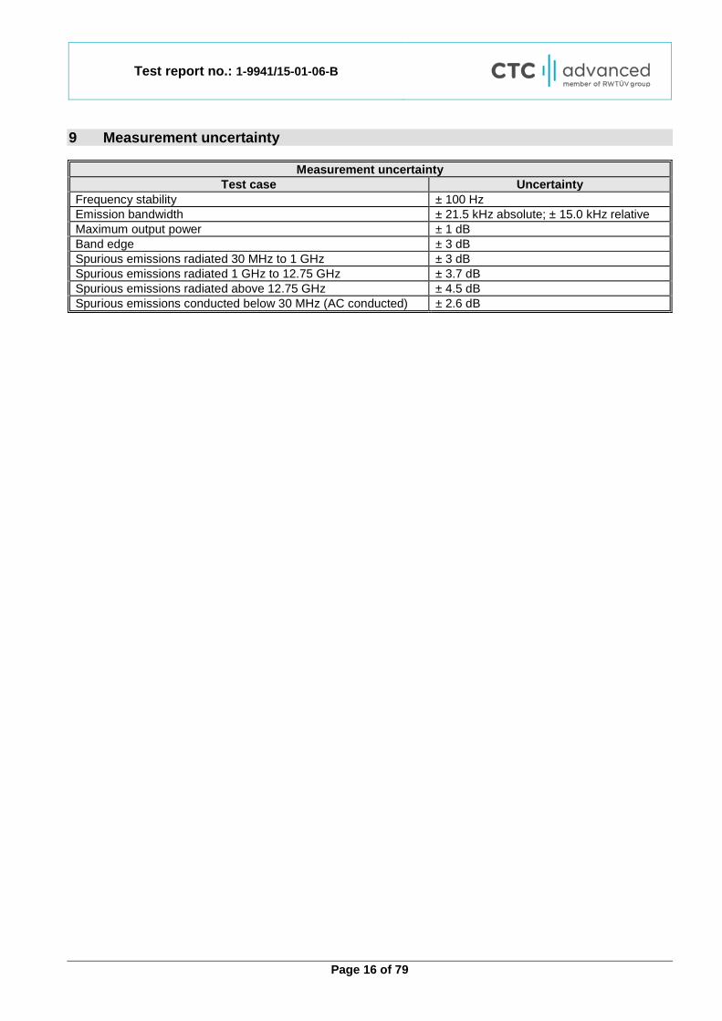
9 Measurement uncertainty
Measurement uncertainty Test case Uncertainty
Frequency stability ± 100 Hz Emission bandwidth ± 21.5 kHz absolute; ± 15.0 kHz relative Maximum output power ± 1 dB Band edge ± 3 dB Spurious emissions radiated 30 MHz to 1 GHz ± 3 dB Spurious emissions radiated 1 GHz to 12.75 GHz ± 3.7 dB Spurious emissions radiated above 12.75 GHz ± 4.5 dB Spurious emissions conducted below 30 MHz (AC conducted) ± 2.6 dB

Test report no.: 1-9941/15-01-06-B
Page 17 of 79
10 Summary of measurement results
☒ No deviations from the technical specifications were ascertained
☐ There were deviations from the technical specifications ascertained
☐ This test report is only a partial test report. The content and verdict of the performed test cases are listed below.
TC Identifier Description Verdict Date Remark
RF-Testing 47 CFR Part 2 47 CFR Part 95 H See table 2017-09-05 -/-
Test
Specification Clause
Test Case Temperature Conditions
Power Source
Voltages C NC NA NP Remark
FCC 47 CFR § 95.628(f)(2) Frequency stability Nominal and
extreme Nominal ☒ ☐ ☐ ☐ -/-
FCC 47 CFR § 95.633(e) Emission bandwidth Nominal Nominal ☒ ☐ ☐ ☐ -/-
FCC 47 CFR § 95.639(f)
Maximum transmit power Nominal Nominal ☒ ☐ ☐ ☐ -/-
FCC 47 CFR § 95.635(d)(7)
Band edge measurements Nominal Nominal ☒ ☐ ☐ ☐ -/-
FCC 47 CFR § 95.635(d)(1)(v)
§ 95.635(d)(3)
Transmitter unwanted radiation Nominal Nominal ☒ ☐ ☐ ☐ -/-
FCC 47 CFR § 95.635(d)(1)(v)
§ 95.635(d)(3)
Receiver spurious emissions (radiated) Nominal Nominal ☒ ☐ ☐ ☐ -/-
FCC 47 CFR § 15.107(a)
§ 15.207
Conducted emissions below 30 MHz
(AC conducted) Nominal Nominal ☐ ☐ ☒ ☐
Battery operated
only
550599 D01 Medical Body Area
Network v01 § 95.628 (c)
Connection interrupt test Nominal Nominal ☒ ☐ ☐ ☐ -/-
Note: C = Compliant; NC = Not compliant; NA = Not Applicable; NP = Not Performed
Test report no.: 1-9941/15-01-06-B
Page 18 of 79
11 Additional comments Reference documents: Customer questionnaire Special test descriptions: Channel 0 (2463 MHz) uses the power setting 2. All channels within the band
2364 MHz to 2390 MHz use power setting 1 and all channels within the band 2390 MHz to 2400 MHz use power setting 5.
Configuration descriptions: None Test mode: ☒ Special software is used. EUT is transmitting pseudo random data by itself Antennas and transmit ☒ Operating mode 1 (single antenna) operating modes: - Equipment with 1 antenna,
- Equipment with 2 diversity antennas operating in switched diversity mode by which at any moment in time only 1 antenna is used,
- Smart antenna system with 2 or more transmit/receive chains, but operating in a mode where only 1 transmit/receive chain is used)
☐ Operating mode 2 (multiple antennas, no beamforming)
- Equipment operating in this mode contains a smart antenna system using two or more transmit/receive chains simultaneously but without beamforming.
☐ Operating mode 3 (multiple antennas, with beamforming)
- Equipment operating in this mode contains a smart antenna system using two or more transmit/receive chains simultaneously with beamforming. In addition to the antenna assembly gain (G), the beamforming gain (Y) may have to be taken into account when performing the measurements.
Expected results for systems test: The timing specification of the MBAN System is as follows:
• MBAN P/C ceases any transmissions in the 2360 – 2390 MHz band < 60 seconds after communication with the MBAN Control Point is lost
• Body-Worn Sensor ceases any transmissions in the 2360 – 2390 MHz band < 6 seconds after the
communication to the MBAN P/C is lost Expected Results for Connection interrupt test (body-worn sensor) in 12.7 according to MBAN System Description (declared from manufacturer) (see Project Note) Timeout for MBAN P/C connection interrupt: 60 seconds Timeout for Body-Worn Sensor connection interrupt: 66 seconds

Test report no.: 1-9941/15-01-06-B
Page 19 of 79
System description (declared from manufacturer):
Project Note Subject: MBAN System Description for FCC Approval Affected Products: Single SRR (FCC ID: PQC- SRRFMPBV1) in
• Avalon CL Fetal & Maternal Pod (866488)
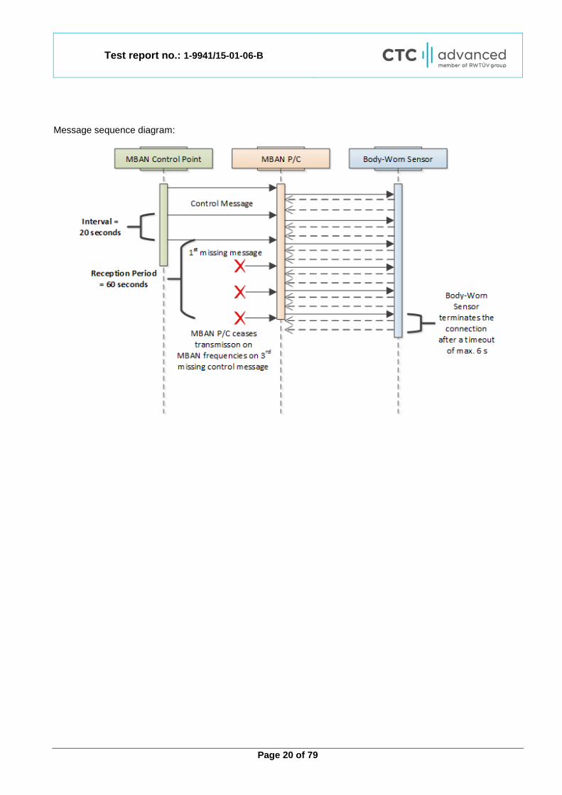
This Project Note is made in order to describe the behavior of an MBAN System with an MBAN Control Point, MBAN P/Cs and Body-Worn Sensors. An MBAN System (1) consists of:
• an MBAN Control Point which coordinates the usage of the restricted 2360 – 2390 MHz band • MBAN P/Cs holding connections to Body-Worn Sensors • Body-Worn Sensors sending data to their MBAN P/C
1 - MBAN System The MBAN Control Point periodically sends a control message to the MBAN P/Cs which includes the following information:
• Channel Mask: An IEEE 802.15.4 channel mask listing the permitted frequencies in the 2360 – 2390 MHz band.
• Reception Period: The period in which the MBAN P/C has to receive at least one control message or has to cease any transmissions in the 2360 – 2390 MHz band.
In the default configuration, the control message is sent at an interval of 20 seconds and the reception period is 60 seconds (three times of the interval). When a MBAN P/C receives a control message from the MBAN Control Point it automatically selects a channel according to the received Channel Mask. This channel is used for connections between the MBAN P/C and Body-Worn Sensors. Also, the MBAN P/C distributes the received Channel Mask in the unrestricted 2390 – 2400 MHz band to the Body-Worn Sensors. The Body-Worn Sensor monitors its connection to the MBAN P/C with a maximum timeout of 6 seconds. If there is no communication within this period the connection is dropped and the Body-Worn Sensor will cease any transmissions in the 2360 – 2390 MHz band. The message flow of the MBAN System is shown in the message sequence diagram. The timing specification of the MBAN System is as follows:
• MBAN P/C ceases any transmissions in the 2360 – 2390 MHz band < 60 seconds after communication with the MBAN Control Point is lost
• Body-Worn Sensor ceases any transmissions in the 2360 – 2390 MHz band < 6 seconds after the communication to the MBAN P/C is lost
Test report no.: 1-9941/15-01-06-B
Page 20 of 79
Message sequence diagram:
Test report no.: 1-9941/15-01-06-B
Page 21 of 79
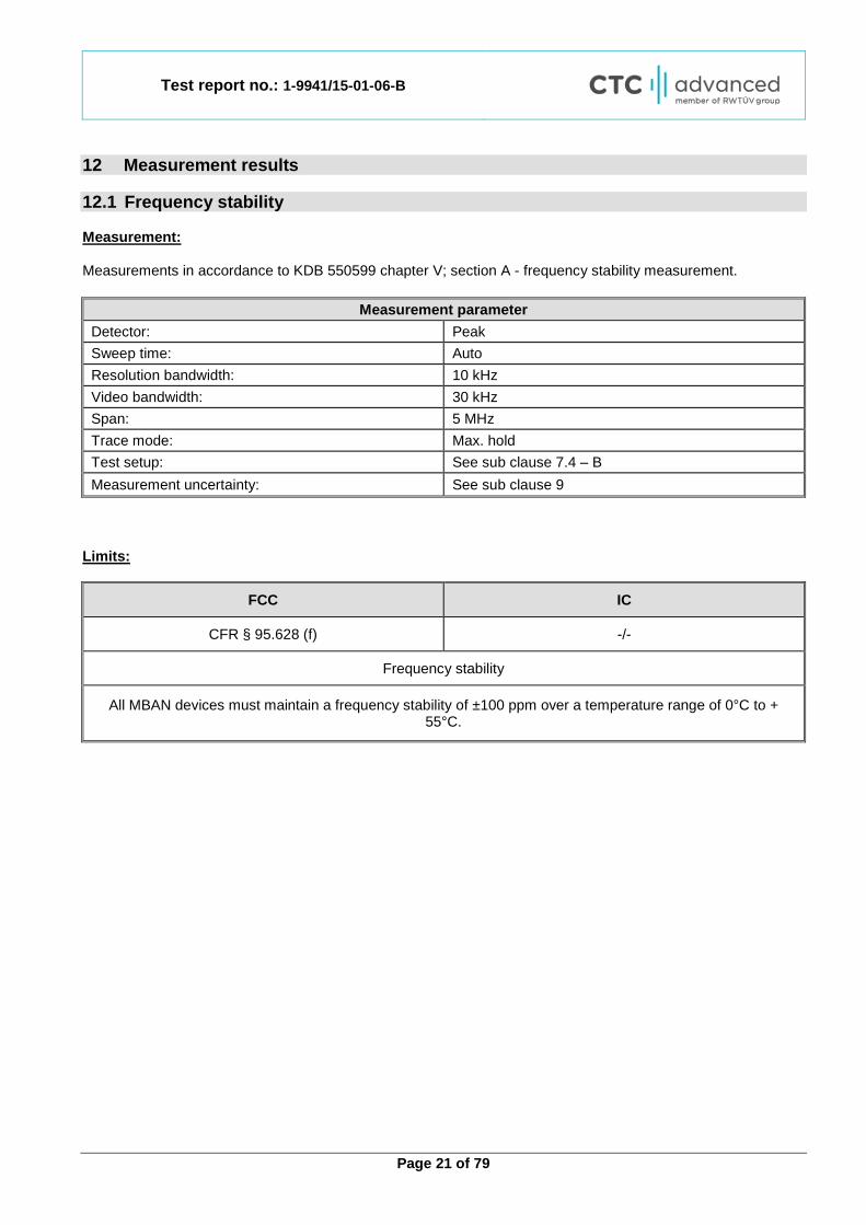
12 Measurement results 12.1 Frequency stability Measurement: Measurements in accordance to KDB 550599 chapter V; section A - frequency stability measurement.
Measurement parameter Detector: Peak Sweep time: Auto Resolution bandwidth: 10 kHz Video bandwidth: 30 kHz Span: 5 MHz Trace mode: Max. hold Test setup: See sub clause 7.4 – B Measurement uncertainty: See sub clause 9
Limits:
FCC IC
CFR § 95.628 (f) -/-
Frequency stability
All MBAN devices must maintain a frequency stability of ±100 ppm over a temperature range of 0°C to + 55°C.

Test report no.: 1-9941/15-01-06-B
Page 22 of 79
Results: Channel low (2363 MHz), lower band
Temp [°C] Time
Measured Frequency
[MHz] Deviation
[kHz] Deviation
[ppm] Verdict
0
Startup 2362.9635 -36.5 -15 Compliant After 2 minutes 2362.9275 -72.5 -31 Compliant After 5 minutes 2362.9635 -36.5 -15 Compliant After 10 minutes 2362.9635 -36.5 -15 Compliant
10
Startup 2362.9395 -60.5 -26 Compliant After 2 minutes 2362.9515 -48.5 -21 Compliant After 5 minutes 2362.9515 -48.5 -21 Compliant After 10 minutes 2362.9515 -48.5 -21 Compliant
20
Startup 2362.9515 -48.5 -21 Compliant After 2 minutes 2362.9635 -36.5 -15 Compliant After 5 minutes 2362.9395 -60.5 -26 Compliant After 10 minutes 2362.9755 -24.5 -10 Compliant
30
Startup 2362.9515 -48.5 -21 Compliant After 2 minutes 2362.9395 -60.5 -26 Compliant After 5 minutes 2362.9515 -48.5 -21 Compliant After 10 minutes 2362.9275 -72.5 -31 Compliant
40
Startup 2362.9515 -48.5 -21 Compliant After 2 minutes 2362.9275 -72.5 -31 Compliant After 5 minutes 2362.9275 -72.5 -31 Compliant After 10 minutes 2362.9395 -60.5 -26 Compliant
50
Startup 2362.9635 -36.5 -15 Compliant After 2 minutes 2362.9395 -60.5 -26 Compliant After 5 minutes 2362.9515 -48.5 -21 Compliant After 10 minutes 2362.9395 -60.5 -26 Compliant
55
Startup 2362.9275 -72.5 -31 Compliant After 2 minutes 2362.9275 -72.5 -31 Compliant After 5 minutes 2362.9275 -72.5 -31 Compliant After 10 minutes 2362.9395 -60.5 -26 Compliant
Test report no.: 1-9941/15-01-06-B
Page 23 of 79
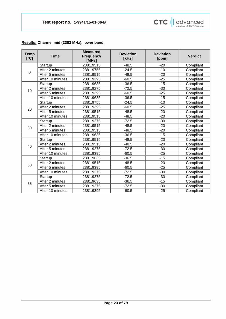
Results: Channel mid (2382 MHz), lower band
Temp [°C] Time
Measured Frequency
[MHz] Deviation
[kHz] Deviation
[ppm] Verdict
0
Startup 2381.9515 -48.5 -20 Compliant After 2 minutes 2381.9755 -24.5 -10 Compliant After 5 minutes 2381.9515 -48.5 -20 Compliant After 10 minutes 2381.9395 -60.5 -25 Compliant
10
Startup 2381.9635 -36.5 -15 Compliant After 2 minutes 2381.9275 -72.5 -30 Compliant After 5 minutes 2381.9395 -60.5 -25 Compliant After 10 minutes 2381.9635 -36.5 -15 Compliant
20
Startup 2381.9755 -24.5 -10 Compliant After 2 minutes 2381.9395 -60.5 -25 Compliant After 5 minutes 2381.9515 -48.5 -20 Compliant After 10 minutes 2381.9515 -48.5 -20 Compliant
30
Startup 2381.9275 -72.5 -30 Compliant After 2 minutes 2381.9515 -48.5 -20 Compliant After 5 minutes 2381.9515 -48.5 -20 Compliant After 10 minutes 2381.9635 -36.5 -15 Compliant
40
Startup 2381.9515 -48.5 -20 Compliant After 2 minutes 2381.9515 -48.5 -20 Compliant After 5 minutes 2381.9275 -72.5 -30 Compliant After 10 minutes 2381.9395 -60.5 -25 Compliant
50
Startup 2381.9635 -36.5 -15 Compliant After 2 minutes 2381.9515 -48.5 -20 Compliant After 5 minutes 2381.9395 -60.5 -25 Compliant After 10 minutes 2381.9275 -72.5 -30 Compliant
55
Startup 2381.9275 -72.5 -30 Compliant After 2 minutes 2381.9635 -36.5 -15 Compliant After 5 minutes 2381.9275 -72.5 -30 Compliant After 10 minutes 2381.9395 -60.5 -25 Compliant
Test report no.: 1-9941/15-01-06-B
Page 24 of 79
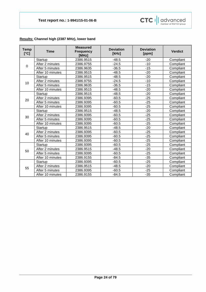
Results: Channel high (2387 MHz), lower band
Temp [°C] Time
Measured Frequency
[MHz] Deviation
[kHz] Deviation
[ppm] Verdict
0
Startup 2386.9515 -48.5 -20 Compliant After 2 minutes 2386.9755 -24.5 -10 Compliant After 5 minutes 2386.9635 -36.5 -15 Compliant After 10 minutes 2386.9515 -48.5 -20 Compliant
10
Startup 2386.9515 -48.5 -20 Compliant After 2 minutes 2386.9755 -24.5 -10 Compliant After 5 minutes 2386.9635 -36.5 -15 Compliant After 10 minutes 2386.9515 -48.5 -20 Compliant
20
Startup 2386.9515 -48.5 -20 Compliant After 2 minutes 2386.9395 -60.5 -25 Compliant After 5 minutes 2386.9395 -60.5 -25 Compliant After 10 minutes 2386.9395 -60.5 -25 Compliant
30
Startup 2386.9515 -48.5 -20 Compliant After 2 minutes 2386.9395 -60.5 -25 Compliant After 5 minutes 2386.9395 -60.5 -25 Compliant After 10 minutes 2386.9395 -60.5 -25 Compliant
40
Startup 2386.9515 -48.5 -20 Compliant After 2 minutes 2386.9395 -60.5 -25 Compliant After 5 minutes 2386.9395 -60.5 -25 Compliant After 10 minutes 2386.9395 -60.5 -25 Compliant
50
Startup 2386.9395 -60.5 -25 Compliant After 2 minutes 2386.9515 -48.5 -20 Compliant After 5 minutes 2386.9395 -60.5 -25 Compliant After 10 minutes 2386.9155 -84.5 -35 Compliant
55
Startup 2386.9395 -60.5 -25 Compliant After 2 minutes 2386.9515 -48.5 -20 Compliant After 5 minutes 2386.9395 -60.5 -25 Compliant After 10 minutes 2386.9155 -84.5 -35 Compliant

Test report no.: 1-9941/15-01-06-B
Page 25 of 79
Results: Channel low (2392 MHz), upper band
Temp [°C] Time
Measured Frequency
[MHz] Deviation
[kHz] Deviation
[ppm] Verdict
0
Startup 2391.9395 -60.5 -25 Compliant After 2 minutes 2391.9395 -60.5 -25 Compliant After 5 minutes 2391.9755 -24.5 -10 Compliant After 10 minutes 2391.9275 -72.5 -30 Compliant
10
Startup 2391.9515 -48.5 -20 Compliant After 2 minutes 2391.9395 -60.5 -25 Compliant After 5 minutes 2391.9515 -48.5 -20 Compliant After 10 minutes 2391.9515 -48.5 -20 Compliant
20
Startup 2391.9515 -48.5 -20 Compliant After 2 minutes 2391.9395 -60.5 -25 Compliant After 5 minutes 2391.9515 -48.5 -20 Compliant After 10 minutes 2391.9515 -48.5 -20 Compliant
30
Startup 2391.9395 -60.5 -25 Compliant After 2 minutes 2391.9395 -60.5 -25 Compliant After 5 minutes 2391.9755 -24.5 -10 Compliant After 10 minutes 2391.9275 -72.5 -30 Compliant
40
Startup 2391.9395 -60.5 -25 Compliant After 2 minutes 2391.9395 -60.5 -25 Compliant After 5 minutes 2391.9755 -24.5 -10 Compliant After 10 minutes 2391.9275 -72.5 -30 Compliant
50
Startup 2391.9155 -84.5 -35 Compliant After 2 minutes 2391.9635 -36.5 -15 Compliant After 5 minutes 2391.9395 -60.5 -25 Compliant After 10 minutes 2391.9275 -72.5 -30 Compliant
55
Startup 2391.9155 -84.5 -35 Compliant After 2 minutes 2391.9635 -36.5 -15 Compliant After 5 minutes 2391.9395 -60.5 -25 Compliant After 10 minutes 2391.9275 -72.5 -30 Compliant

Test report no.: 1-9941/15-01-06-B
Page 26 of 79
Results: Channel high (2397 MHz), upper band
Temp [°C] Time
Measured Frequency
[MHz] Deviation
[kHz] Deviation
[ppm] Verdict
0
Startup 2396.9275 -72.5 -30 Compliant After 2 minutes 2396.9395 -60.5 -25 Compliant After 5 minutes 2396.9395 -60.5 -25 Compliant After 10 minutes 2396.9635 -36.5 -15 Compliant
10
Startup 2396.9395 -60.5 -25 Compliant After 2 minutes 2396.9875 -12.5 -5 Compliant After 5 minutes 2396.9875 -12.5 -5 Compliant After 10 minutes 2396.9275 -72.5 -30 Compliant
20
Startup 2396.9635 -36.5 -15 Compliant After 2 minutes 2396.9755 -24.5 -10 Compliant After 5 minutes 2396.9515 -48.5 -20 Compliant After 10 minutes 2396.9275 -72.5 -30 Compliant
30
Startup 2396.9755 -24.5 -10 Compliant After 2 minutes 2396.9635 -36.5 -15 Compliant After 5 minutes 2396.9515 -48.5 -20 Compliant After 10 minutes 2396.9395 -60.5 -25 Compliant
40
Startup 2396.9275 -72.5 -30 Compliant After 2 minutes 2396.9275 -72.5 -30 Compliant After 5 minutes 2396.9275 -72.5 -30 Compliant After 10 minutes 2396.9395 -60.5 -25 Compliant
50
Startup 2396.9275 -72.5 -30 Compliant After 2 minutes 2396.9755 -24.5 -10 Compliant After 5 minutes 2396.9515 -48.5 -20 Compliant After 10 minutes 2396.9395 -60.5 -25 Compliant
55
Startup 2396.9515 -48.5 -20 Compliant After 2 minutes 2396.9515 -48.5 -20 Compliant After 5 minutes 2396.9395 -60.5 -25 Compliant After 10 minutes 2396.9515 -48.5 -20 Compliant

Test report no.: 1-9941/15-01-06-B
Page 27 of 79
12.2 Emission bandwidth Measurement: Measurements were made in accordance with the requirements detailed in FCC Part 95, Section 95.633(e)(3) - emission bandwidth with reference to KDB 558074 DTS 2.0.
Measurement parameter Detector: Peak Sweep time: Auto Resolution bandwidth: 30 kHz Video bandwidth: 100 kHz Span: 5 MHz Trace mode: Max. hold Test setup: See sub clause 7.4 – A Measurement uncertainty: See sub clause 9
Limits:
FCC IC
CFR § 95.633 (e)(1)(3) -/-
Emission bandwidth will be determined by measuring the width of the signal between points, one below the carrier center
frequency and one above the carrier center frequency, that are 20 dB down relative to the maximum level of the modulated carrier. Compliance with the emission bandwidth limit is based on the use of measurement instrumentation employing a peak detector function with an instrument resolution bandwidth approximately equal to 1.0 percent of the
emission bandwidth of the device under measurement.
For stations operating in 2360-2400 MHz, the maximum authorized emission bandwidth is 5 megahertz. Results:
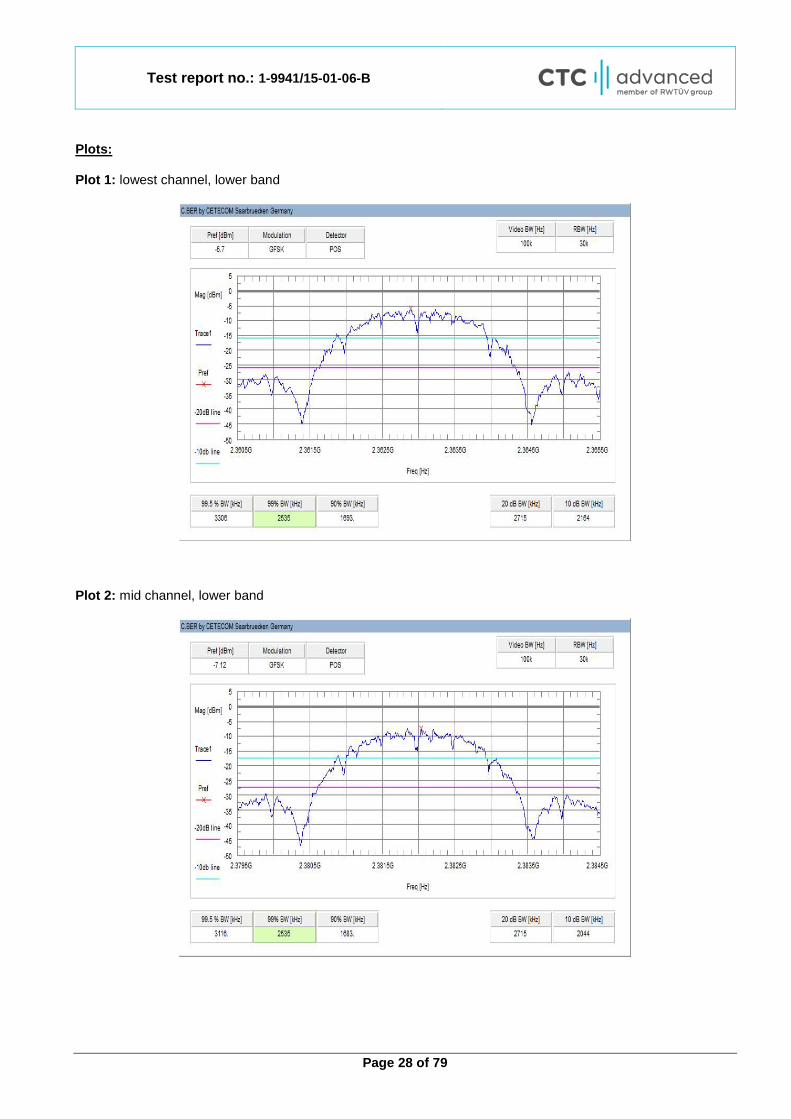
Channel Frequency [MHz]
Emission bandwidth [kHz]
Low (lower band) 2363 2715
Mid (lower band) 2382 2715
High (lower band) 2387 2695
Low (upper band) 2392 2756
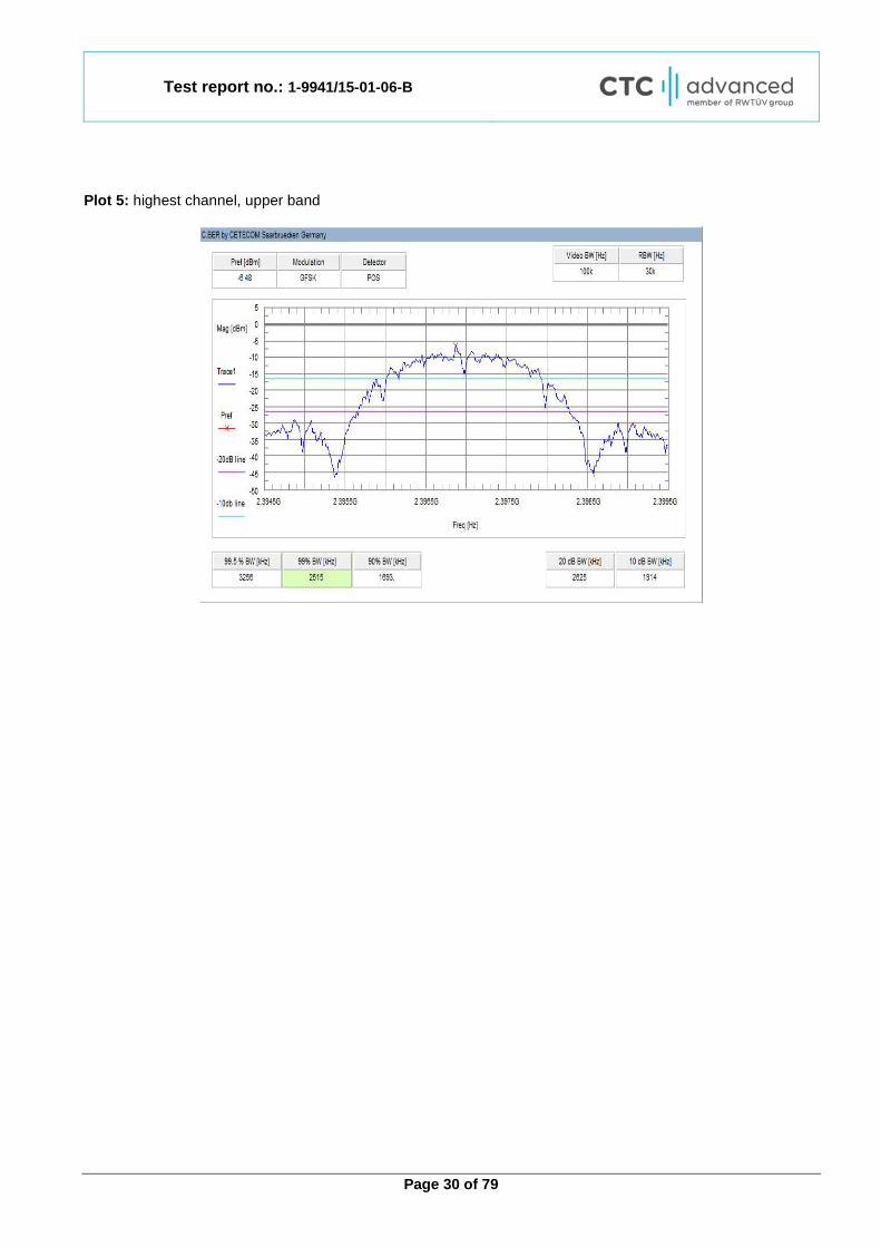
High (upper band) 2397 2625
Test report no.: 1-9941/15-01-06-B
Page 28 of 79
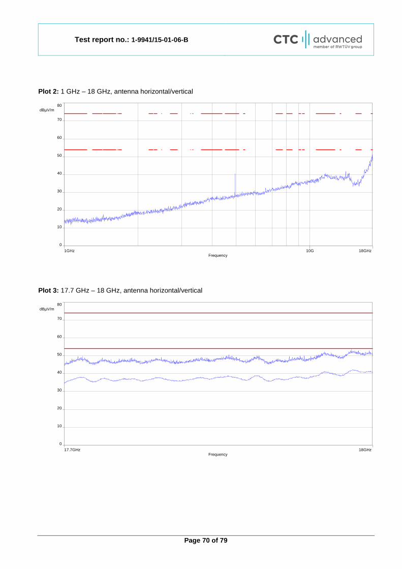
Plots: Plot 1: lowest channel, lower band
Plot 2: mid channel, lower band

Test report no.: 1-9941/15-01-06-B
Page 29 of 79
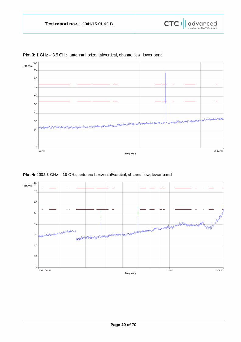
Plot 3: highest channel, lower band
Plot 4: lowest channel, upper band
Test report no.: 1-9941/15-01-06-B
Page 30 of 79
Plot 5: highest channel, upper band
Test report no.: 1-9941/15-01-06-B
Page 31 of 79
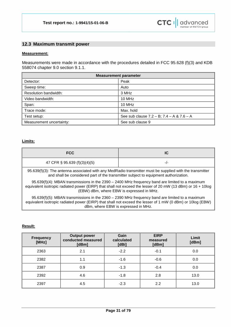
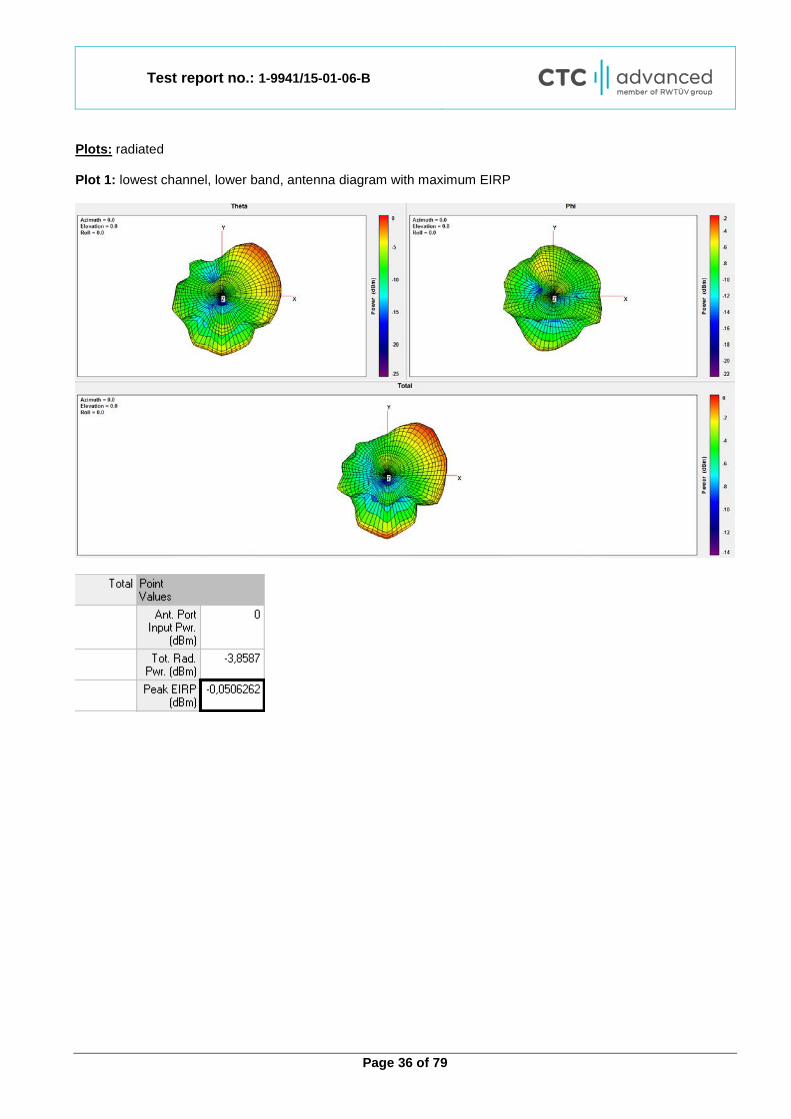
12.3 Maximum transmit power Measurement: Measurements were made in accordance with the procedures detailed in FCC 95.628 (f)(3) and KDB 558074 chapter 9.0 section 9.1.1.
Measurement parameter Detector: Peak Sweep time: Auto Resolution bandwidth: 3 MHz Video bandwidth: 10 MHz Span: 10 MHz Trace mode: Max. hold Test setup: See sub clause 7.2 – B; 7.4 – A & 7.6 – A Measurement uncertainty: See sub clause 9
Limits:
FCC IC
47 CFR § 95.639 (f)(3)(4)(5) -/-
95.639(f)(3): The antenna associated with any MedRadio transmitter must be supplied with the transmitter and shall be considered part of the transmitter subject to equipment authorization.
95.639(f)(4): MBAN transmissions in the 2390 – 2400 MHz frequency band are limited to a maximum equivalent isotropic radiated power (EIRP) that shall not exceed the lesser of 20 mW (13 dBm) or 16 + 10log
(EBW) dBm, where EBW is expressed in MHz.
95.639(f)(5): MBAN transmissions in the 2360 – 2390 MHz frequency band are limited to a maximum equivalent isotropic radiated power (EIRP) that shall not exceed the lesser of 1 mW (0 dBm) or 10log (EBW)
dBm, where EBW is expressed in MHz. Result:
Frequency [MHz]
Output power conducted measured
[dBm]
Gain calculated
[dBi]
EIRP measured
[dBm] Limit [dBm]
2363 2.1 -2.2 -0.1 0.0
2382 1.1 -1.6 -0.6 0.0
2387 0.9 -1.3 -0.4 0.0
2392 4.6 -1.8 2.8 13.0
2397 4.5 -2.3 2.2 13.0
Test report no.: 1-9941/15-01-06-B
Page 32 of 79
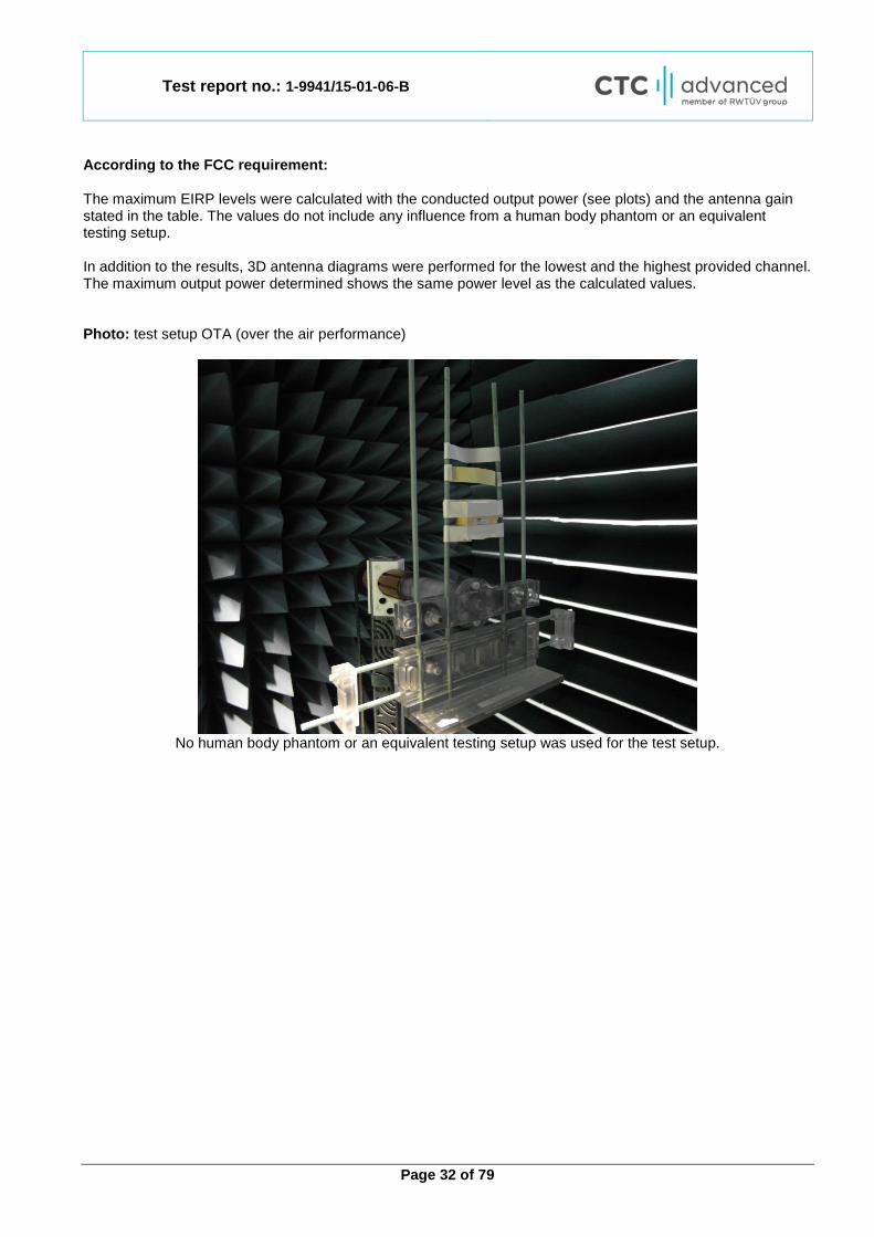
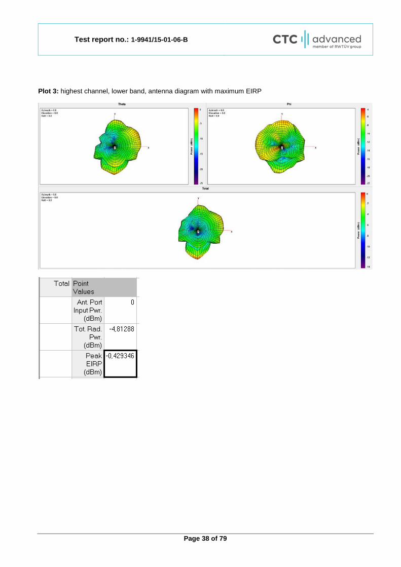
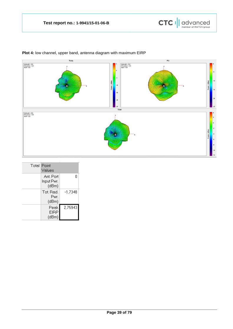
According to the FCC requirement: The maximum EIRP levels were calculated with the conducted output power (see plots) and the antenna gain stated in the table. The values do not include any influence from a human body phantom or an equivalent testing setup. In addition to the results, 3D antenna diagrams were performed for the lowest and the highest provided channel. The maximum output power determined shows the same power level as the calculated values. Photo: test setup OTA (over the air performance)
No human body phantom or an equivalent testing setup was used for the test setup.

Test report no.: 1-9941/15-01-06-B
Page 33 of 79
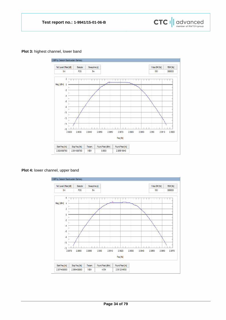
Plots: conducted Plot 1: lowest channel, lower band
Plot 2: mid channel, lower band
Test report no.: 1-9941/15-01-06-B
Page 34 of 79
Plot 3: highest channel, lower band
Plot 4: lower channel, upper band
Test report no.: 1-9941/15-01-06-B
Page 35 of 79
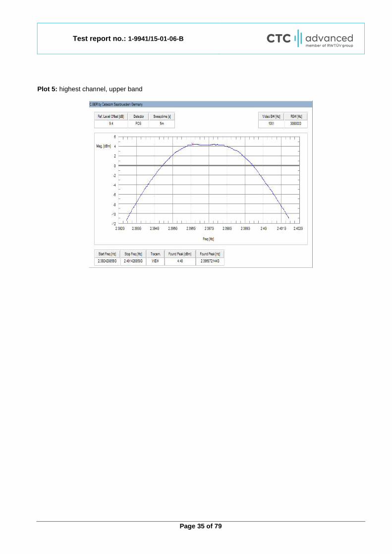
Plot 5: highest channel, upper band
Test report no.: 1-9941/15-01-06-B
Page 36 of 79
Plots: radiated Plot 1: lowest channel, lower band, antenna diagram with maximum EIRP

Test report no.: 1-9941/15-01-06-B
Page 37 of 79
Plot 2: mid channel, lower band, antenna diagram with maximum EIRP
Test report no.: 1-9941/15-01-06-B
Page 38 of 79
Plot 3: highest channel, lower band, antenna diagram with maximum EIRP
Test report no.: 1-9941/15-01-06-B
Page 39 of 79
Plot 4: low channel, upper band, antenna diagram with maximum EIRP

Test report no.: 1-9941/15-01-06-B
Page 40 of 79
Plot 5: highest channel, upper band, antenna diagram with maximum EIRP
Test report no.: 1-9941/15-01-06-B
Page 41 of 79
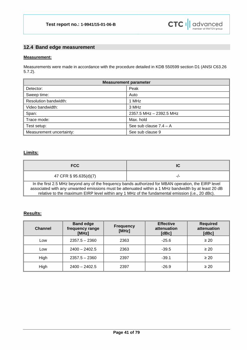
12.4 Band edge measurement Measurement: Measurements were made in accordance with the procedure detailed in KDB 550599 section D1 (ANSI C63.26 5.7.2).
Measurement parameter Detector: Peak Sweep time: Auto Resolution bandwidth: 1 MHz Video bandwidth: 3 MHz Span: 2357.5 MHz – 2392.5 MHz Trace mode: Max. hold Test setup: See sub clause 7.4 – A Measurement uncertainty: See sub clause 9
Limits:
FCC IC
47 CFR § 95.635(d)(7) -/-
In the first 2.5 MHz beyond any of the frequency bands authorized for MBAN operation, the EIRP level associated with any unwanted emissions must be attenuated within a 1 MHz bandwidth by at least 20 dB
relative to the maximum EIRP level within any 1 MHz of the fundamental emission (i.e., 20 dBc). Results:
Channel Band edge
frequency range [MHz]
Frequency [MHz]
Effective attenuation
[dBc]
Required attenuation
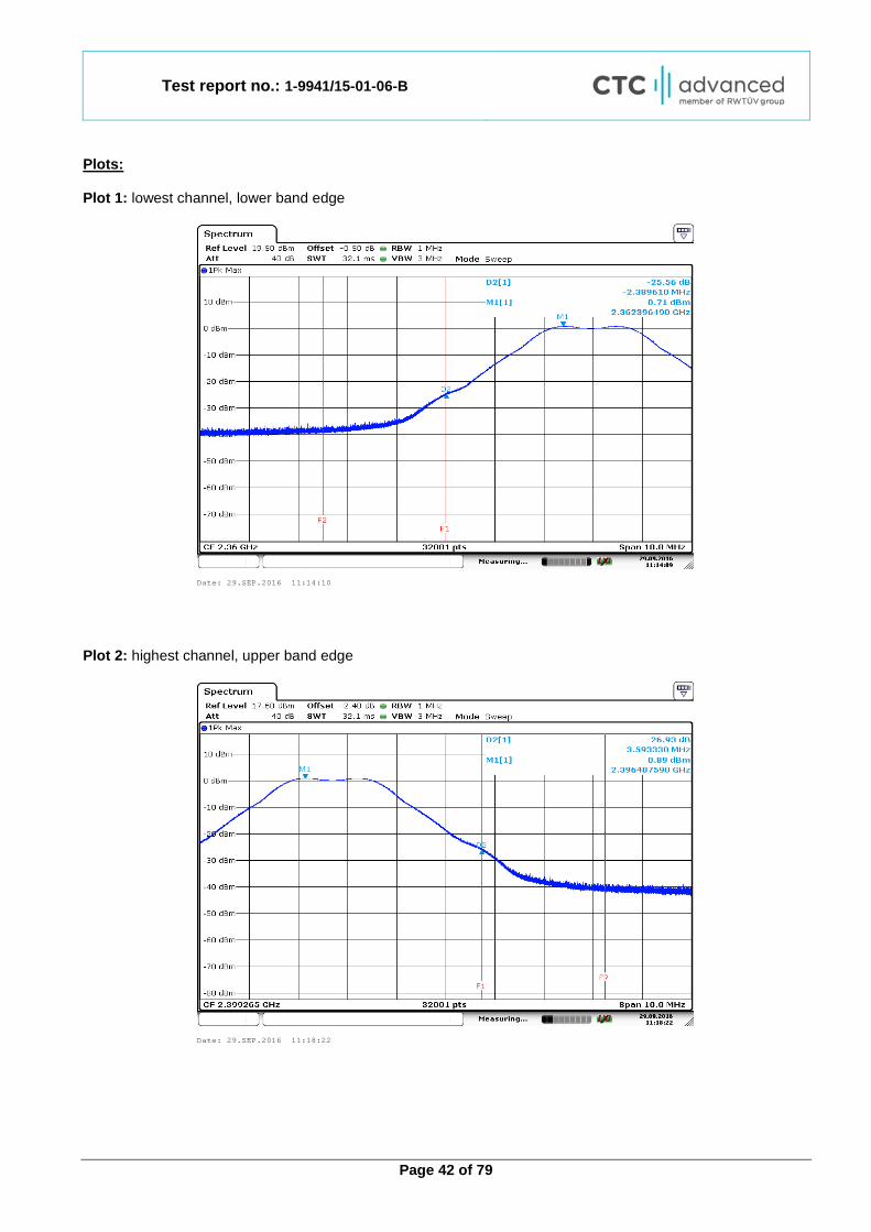
[dBc] Low 2357.5 – 2360 2363 -25.6 ≥ 20
Low 2400 – 2402.5 2363 -39.5 ≥ 20
High 2357.5 – 2360 2397 -39.1 ≥ 20
High 2400 – 2402.5 2397 -26.9 ≥ 20
Test report no.: 1-9941/15-01-06-B
Page 42 of 79
Plots: Plot 1: lowest channel, lower band edge
Plot 2: highest channel, upper band edge
Date: 29.SEP.2016 11:14:10
Date: 29.SEP.2016 11:18:22
Test report no.: 1-9941/15-01-06-B
Page 43 of 79
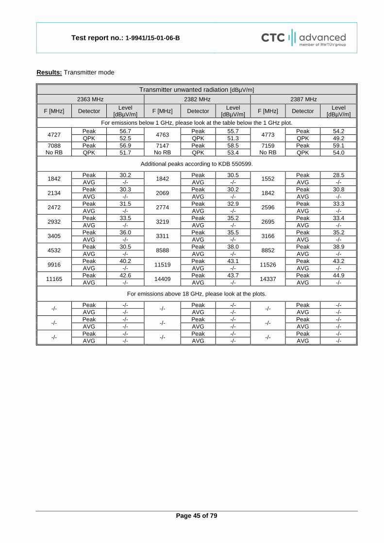
12.5 Transmitter unwanted radiation (radiated) Measurement: Measurements were made in accordance with the procedure detailed in KDB 550599 section D2.
Measurement parameter
Detector: Prescan: Peak Final: QPK below 960 MHz RMS above 960 MHz
Video bandwidth:
9 kHz – 150 kHz: 1 kHz 150 kHz – 30 MHz: 30 kHz 30 MHz – 1 GHz: 300 kHz 1 GHz – 26 GHz: 3 MHz
Resolution bandwidth:
9 kHz – 150 kHz: 200 Hz 150 kHz – 30 MHz: 9 kHz 30 MHz – 1 GHz: 100 kHz 1 GHz – 26 GHz: 1 MHz
Span: See plots Trace mode: Max Hold Test setup: See sub clause 7.1 – A & 7.2 – A & 7.3 – A Measurement uncertainty: See sub clause 9
Limits:
FCC IC
47 CFR § 15.109 47 CFR § 95.635(d)(1)(v), 95.635(d)(3) -/-
Transmitter unwanted radiation (radiated)
Frequency (MHz) Field strength (µV/m) 1 Measurement distance (m)
0.009 – 0.490 2400/F(kHz) 300 0.490 – 1.705 24000/F(kHz) 30 1.705 – 30.0 30 30
30 - 88 100 (40 dBµV/m) 3 30 - 88 31.6 (30 dBµV/m) 10 88 - 216 150 (43.5 dBµV/m) 3 88 - 216 47.3 (33.5 dBµV/m) 10 216 - 960 200 (46 dBµV/m) 3 216 - 960 63.1 (36 dBµV/m) 10 above 960 500 (54 dBµV/m) 3
1 Measurements in the 9 to 90 kHz, 110 to 490 kHz and above 1000 MHz ranges employ an average detector. Otherwise a quasi-peak detector is used.
Test report no.: 1-9941/15-01-06-B
Page 44 of 79
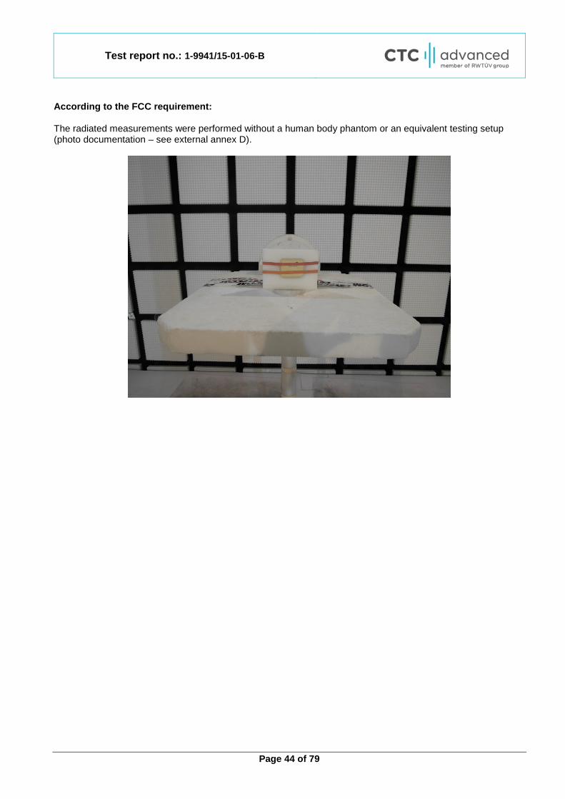
According to the FCC requirement: The radiated measurements were performed without a human body phantom or an equivalent testing setup (photo documentation – see external annex D).
Test report no.: 1-9941/15-01-06-B
Page 45 of 79
Results: Transmitter mode
Transmitter unwanted radiation [dBµV/m] 2363 MHz 2382 MHz 2387 MHz
F [MHz] Detector Level [dBµV/m] F [MHz] Detector Level
[dBµV/m] F [MHz] Detector Level [dBµV/m]
For emissions below 1 GHz, please look at the table below the 1 GHz plot.
4727 Peak 56.7 4763 Peak 55.7 4773 Peak 54.2 QPK 52.5 QPK 51.3 QPK 49.2
7088 No RB
Peak 56.9 7147 No RB
Peak 58.5 7159 No RB
Peak 59.1 QPK 51.7 QPK 53.4 QPK 54.0
Additional peaks according to KDB 550599.
1842 Peak 30.2 1842 Peak 30.5 1552 Peak 28.5 AVG -/- AVG -/- AVG -/-
2134 Peak 30.3 2069 Peak 30.2 1842 Peak 30.8 AVG -/- AVG -/- AVG -/-
2472 Peak 31.5 2774 Peak 32.9 2596 Peak 33.3 AVG -/- AVG -/- AVG -/-
2932 Peak 33.5 3219 Peak 35.2 2695 Peak 33.4 AVG -/- AVG -/- AVG -/-
3405 Peak 36.0 3311 Peak 35.5 3166 Peak 35.2 AVG -/- AVG -/- AVG -/-
4532 Peak 30.5 8588 Peak 38.0 8852 Peak 38.9 AVG -/- AVG -/- AVG -/-
9916 Peak 40.2 11519 Peak 43.1 11526 Peak 43.2 AVG -/- AVG -/- AVG -/-
11165 Peak 42.6 14409 Peak 43.7 14337 Peak 44.9 AVG -/- AVG -/- AVG -/-
For emissions above 18 GHz, please look at the plots.
-/- Peak -/- -/- Peak -/- -/- Peak -/- AVG -/- AVG -/- AVG -/-
-/- Peak -/- -/- Peak -/- -/- Peak -/- AVG -/- AVG -/- AVG -/-
-/- Peak -/- -/- Peak -/- -/- Peak -/- AVG -/- AVG -/- AVG -/-
Test report no.: 1-9941/15-01-06-B
Page 46 of 79
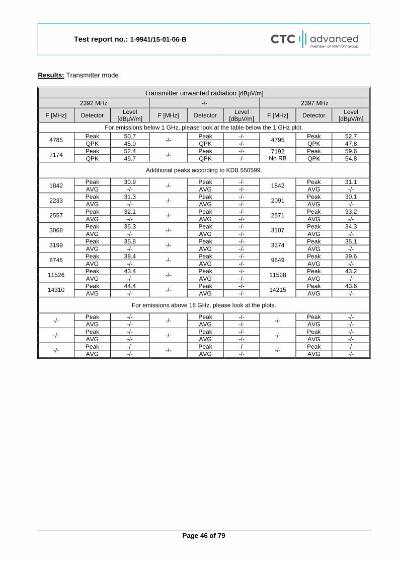
Results: Transmitter mode
Transmitter unwanted radiation [dBµV/m] 2392 MHz -/- 2397 MHz
F [MHz] Detector Level [dBµV/m] F [MHz] Detector Level
[dBµV/m] F [MHz] Detector Level [dBµV/m]
For emissions below 1 GHz, please look at the table below the 1 GHz plot.
4785 Peak 50.7 -/- Peak -/- 4795 Peak 52.7 QPK 45.0 QPK -/- QPK 47.8
7174 Peak 52.4 -/- Peak -/- 7192 No RB
Peak 59.6 QPK 45.7 QPK -/- QPK 54.8
Additional peaks according to KDB 550599.
1842 Peak 30.9 -/- Peak -/- 1842 Peak 31.1 AVG -/- AVG -/- AVG -/-
2233 Peak 31.3 -/- Peak -/- 2091 Peak 30.1 AVG -/- AVG -/- AVG -/-
2557 Peak 32.1 -/- Peak -/- 2571 Peak 33.2 AVG -/- AVG -/- AVG -/-
3068 Peak 35.3 -/- Peak -/- 3107 Peak 34.3 AVG -/- AVG -/- AVG -/-
3199 Peak 35.8 -/- Peak -/- 3374 Peak 35.1 AVG -/- AVG -/- AVG -/-
8746 Peak 38.4 -/- Peak -/- 9849 Peak 39.6 AVG -/- AVG -/- AVG -/-
11526 Peak 43.4 -/- Peak -/- 11528 Peak 43.2 AVG -/- AVG -/- AVG -/-
14310 Peak 44.4 -/- Peak -/- 14215 Peak 43.6 AVG -/- AVG -/- AVG -/-
For emissions above 18 GHz, please look at the plots.
-/- Peak -/- -/- Peak -/- -/- Peak -/- AVG -/- AVG -/- AVG -/-
-/- Peak -/- -/- Peak -/- -/- Peak -/- AVG -/- AVG -/- AVG -/-
-/- Peak -/- -/- Peak -/- -/- Peak -/- AVG -/- AVG -/- AVG -/-
Test report no.: 1-9941/15-01-06-B
Page 47 of 79
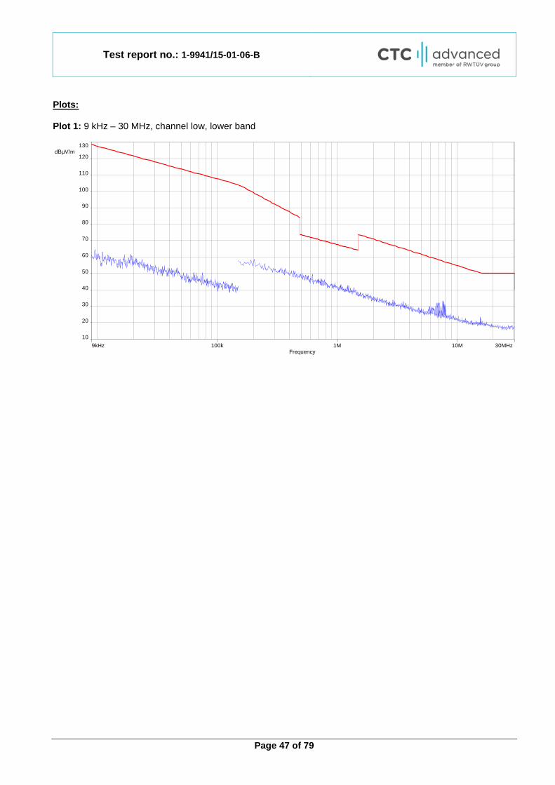
Plots: Plot 1: 9 kHz – 30 MHz, channel low, lower band
9kHz 30MHz10M1M100kFrequency
10
130 dBµV/m
120
90
60
30
110
80
50
20
100
70
40

Test report no.: 1-9941/15-01-06-B
Page 48 of 79
Plot 2: 30 MHz – 1 GHz, channel low, lower band
Final_Result:
Frequency (MHz)
QuasiPeak (dBµV/m)
Limit (dBµV/m)
Margin (dB)
Meas. Time (ms)
Bandwidth (kHz)
Height (cm) Pol Azimuth
(deg) Corr. (dB)
32.726550 10.29 30.00 19.71 1000.0 120.000 101.0 H 80.0 13.6 41.020350 10.89 30.00 19.11 1000.0 120.000 101.0 H 280.0 14.0 53.943450 8.65 30.00 21.35 1000.0 120.000 101.0 V 100.0 12.0
602.377800 18.37 36.00 17.63 1000.0 120.000 98.0 H -9.0 20.7 721.645050 19.58 36.00 16.42 1000.0 120.000 170.0 H 190.0 22.0 889.832550 21.52 36.00 14.48 1000.0 120.000 170.0 H 190.0 24.0
0
10
20
30
40
50
60
70
80
30M 50 60 80 100M 200 300 400 500 800 1,05G
Leve
l in
dBµV
/m
Frequency in Hz
FCC_10m_B
Test report no.: 1-9941/15-01-06-B
Page 49 of 79
Plot 3: 1 GHz – 3.5 GHz, antenna horizontal/vertical, channel low, lower band
Plot 4: 2392.5 GHz – 18 GHz, antenna horizontal/vertical, channel low, lower band
1GHz 3.5GHzFrequency
0
100 dBµV/m
80
50
20
70
40
10
90
60
30
2.3925GHz 18GHz10GFrequency
0
80 dBµV/m
50
20
70
40
10
60
30

Test report no.: 1-9941/15-01-06-B
Page 50 of 79
Plot 5: 17.7 GHz – 18 GHz, antenna horizontal/vertical, channel low, lower band
Plot 6: 18 GHz – 26 GHz, antenna horizontal/vertical, channel low, lower band
17.7GHz 18GHzFrequency
0
80 dBµV/m
50
20
70
40
10
60
30
Date: 30.AUG.2016 16:24:22
Test report no.: 1-9941/15-01-06-B
Page 51 of 79
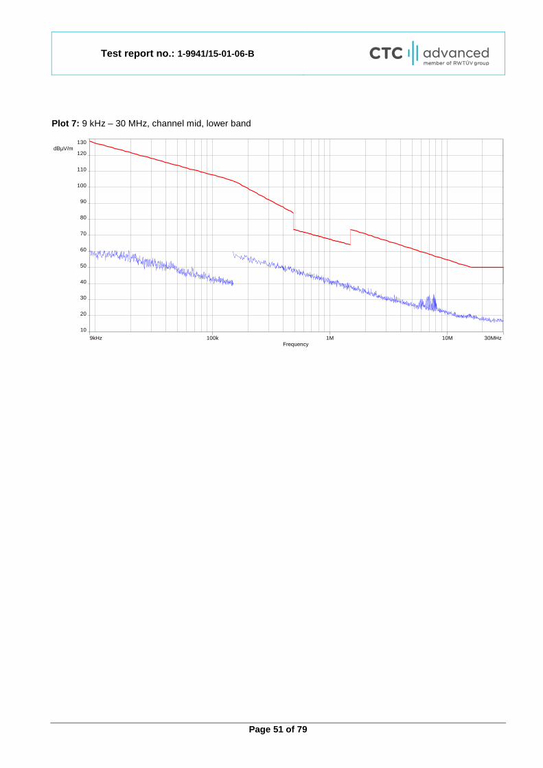
Plot 7: 9 kHz – 30 MHz, channel mid, lower band
9kHz 30MHz10M1M100kFrequency
10
130 dBµV/m
120
90
60
30
110
80
50
20
100
70
40
Test report no.: 1-9941/15-01-06-B
Page 52 of 79
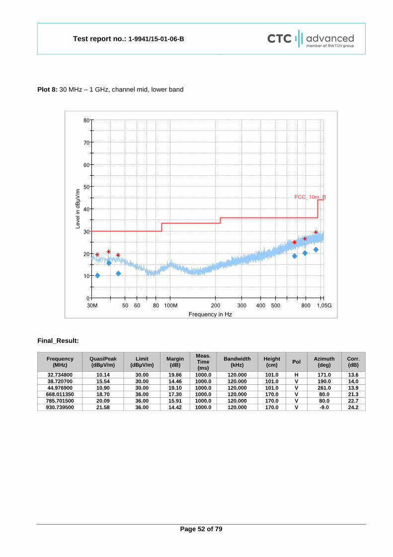
Plot 8: 30 MHz – 1 GHz, channel mid, lower band
Final_Result:
Frequency (MHz)
QuasiPeak (dBµV/m)
Limit (dBµV/m)
Margin (dB)
Meas. Time (ms)
Bandwidth (kHz)
Height (cm) Pol Azimuth
(deg) Corr. (dB)
32.734800 10.14 30.00 19.86 1000.0 120.000 101.0 H 171.0 13.6 38.720700 15.54 30.00 14.46 1000.0 120.000 101.0 V 190.0 14.0 44.976900 10.90 30.00 19.10 1000.0 120.000 101.0 V 261.0 13.9
668.011350 18.70 36.00 17.30 1000.0 120.000 170.0 V 80.0 21.3 785.701500 20.09 36.00 15.91 1000.0 120.000 170.0 V 80.0 22.7 930.739500 21.58 36.00 14.42 1000.0 120.000 170.0 V -9.0 24.2
0
10
20
30
40
50
60
70
80
30M 50 60 80 100M 200 300 400 500 800 1,05G
Leve
l in
dBµV
/m
Frequency in Hz
FCC_10m_B
Test report no.: 1-9941/15-01-06-B
Page 53 of 79
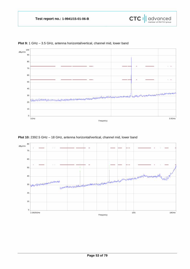
Plot 9: 1 GHz – 3.5 GHz, antenna horizontal/vertical, channel mid, lower band
Plot 10: 2392.5 GHz – 18 GHz, antenna horizontal/vertical, channel mid, lower band
1GHz 3.5GHzFrequency
0
100 dBµV/m
80
50
20
70
40
10
90
60
30
2.3925GHz 18GHz10GFrequency
0
80 dBµV/m
50
20
70
40
10
60
30

Test report no.: 1-9941/15-01-06-B
Page 54 of 79
Plot 11: 17.7 GHz – 18 GHz, antenna horizontal/vertical, channel mid, lower band
Plot 12: 18 GHz – 26 GHz, antenna horizontal/vertical, channel mid, lower band
17.7GHz 18GHzFrequency
0
80 dBµV/m
50
20
70
40
10
60
30
Date: 30.AUG.2016 16:25:03
Test report no.: 1-9941/15-01-06-B
Page 55 of 79
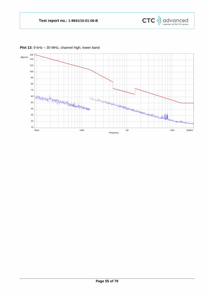
Plot 13: 9 kHz – 30 MHz, channel high, lower band
9kHz 30MHz10M1M100kFrequency
10
130 dBµV/m
120
90
60
30
110
80
50
20
100
70
40
Test report no.: 1-9941/15-01-06-B
Page 56 of 79
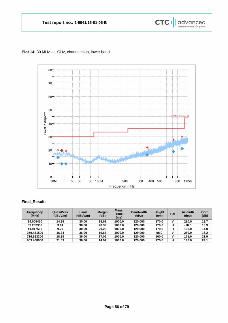
Plot 14: 30 MHz – 1 GHz, channel high, lower band
Final_Result:
Frequency (MHz)
QuasiPeak (dBµV/m)
Limit (dBµV/m)
Margin (dB)
Meas. Time (ms)
Bandwidth (kHz)
Height (cm) Pol Azimuth
(deg) Corr. (dB)
34.008450 14.39 30.00 15.61 1000.0 120.000 170.0 V 280.0 13.7 37.282350 9.61 30.00 20.39 1000.0 120.000 170.0 H -10.0 13.9 41.917500 9.77 30.00 20.23 1000.0 120.000 170.0 H 100.0 14.0 359.461500 16.34 36.00 19.66 1000.0 120.000 98.0 V 280.0 16.2 716.883300 18.95 36.00 17.05 1000.0 120.000 100.0 V 171.0 21.9 903.408900 21.03 36.00 14.97 1000.0 120.000 170.0 H 190.0 24.1
0
10
20
30
40
50
60
70
80
30M 50 60 80 100M 200 300 400 500 800 1,05G
Leve
l in
dBµV
/m
Frequency in Hz
FCC_10m_B
Test report no.: 1-9941/15-01-06-B
Page 57 of 79
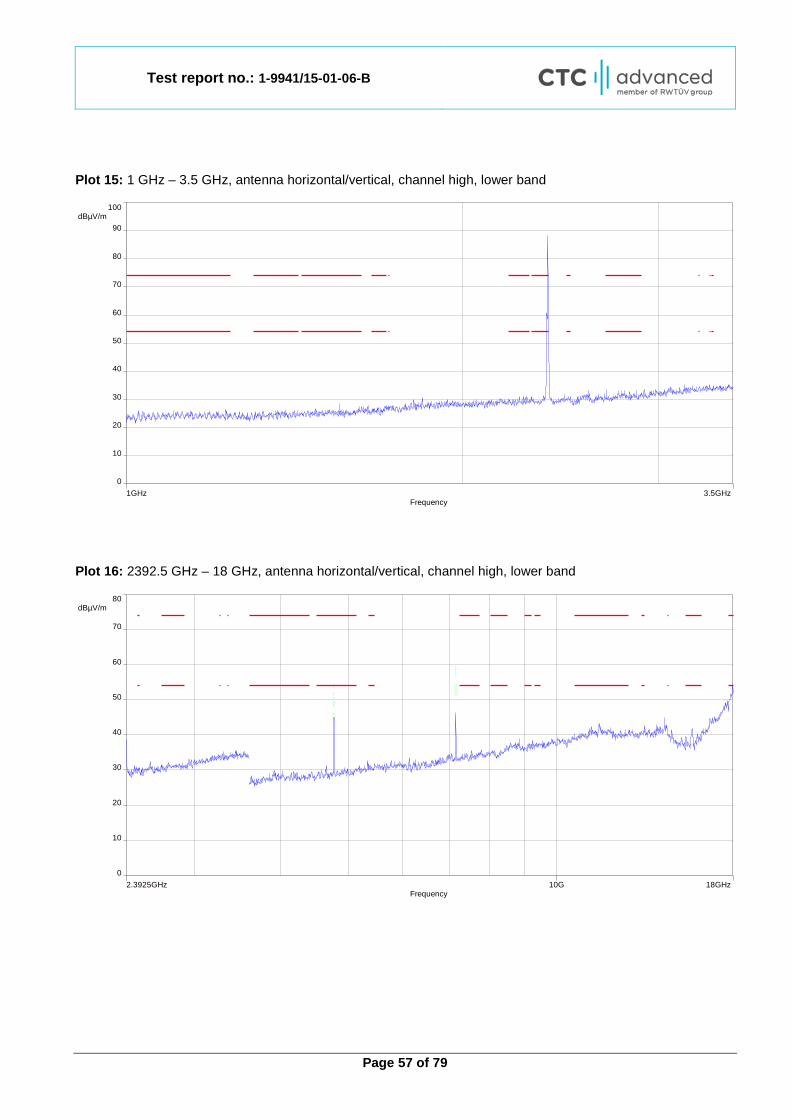
Plot 15: 1 GHz – 3.5 GHz, antenna horizontal/vertical, channel high, lower band
Plot 16: 2392.5 GHz – 18 GHz, antenna horizontal/vertical, channel high, lower band
1GHz 3.5GHzFrequency
0
100 dBµV/m
80
50
20
70
40
10
90
60
30
2.3925GHz 18GHz10GFrequency
0
80 dBµV/m
50
20
70
40
10
60
30

Test report no.: 1-9941/15-01-06-B
Page 58 of 79
Plot 17: 17.7 GHz – 18 GHz, antenna horizontal/vertical, channel high, lower band
Plot 18: 18 GHz – 26 GHz, antenna horizontal/vertical, channel high, lower band
17.7GHz 18GHzFrequency
0
80 dBµV/m
50
20
70
40
10
60
30
Date: 9.SEP.2016 06:27:34
Test report no.: 1-9941/15-01-06-B
Page 59 of 79
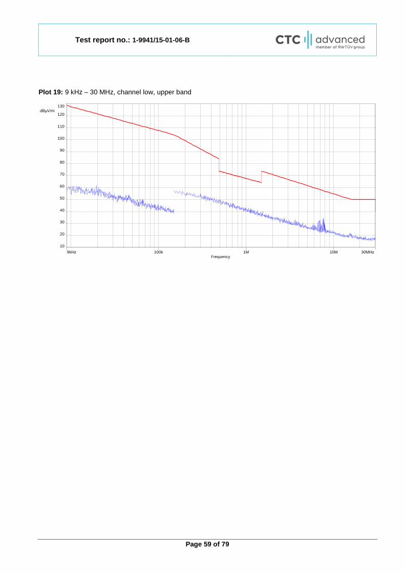
Plot 19: 9 kHz – 30 MHz, channel low, upper band
9kHz 30MHz10M1M100kFrequency
10
130 dBµV/m
120
90
60
30
110
80
50
20
100
70
40

Test report no.: 1-9941/15-01-06-B
Page 60 of 79
Plot 20: 30 MHz – 1 GHz, channel low, upper band
Final_Result:
Frequency (MHz)
QuasiPeak (dBµV/m)
Limit (dBµV/m)
Margin (dB)
Meas. Time (ms)
Bandwidth (kHz)
Height (cm) Pol Azimuth
(deg) Corr. (dB)
36.248550 10.43 30.00 19.57 1000.0 120.000 101.0 V 190.0 13.9 40.675950 10.58 30.00 19.42 1000.0 120.000 170.0 V 280.0 14.0 44.460000 10.03 30.00 19.97 1000.0 120.000 170.0 V -9.0 13.9 439.654950 13.14 36.00 22.86 1000.0 120.000 101.0 V 190.0 17.5 702.212250 18.63 36.00 17.37 1000.0 120.000 170.0 H 260.0 21.6 829.345050 20.12 36.00 15.88 1000.0 120.000 98.0 H 80.0 23.2
0
10
20
30
40
50
60
70
80
30M 50 60 80 100M 200 300 400 500 800 1,05G
Leve
l in
dBµV
/m
Frequency in Hz
FCC_10m_B
Test report no.: 1-9941/15-01-06-B
Page 61 of 79
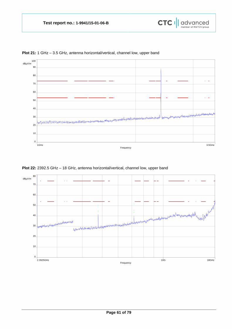
Plot 21: 1 GHz – 3.5 GHz, antenna horizontal/vertical, channel low, upper band
Plot 22: 2392.5 GHz – 18 GHz, antenna horizontal/vertical, channel low, upper band
1GHz 3.5GHzFrequency
0
100 dBµV/m
80
50
20
70
40
10
90
60
30
2.3925GHz 18GHz10GFrequency
0
80 dBµV/m
50
20
70
40
10
60
30
Test report no.: 1-9941/15-01-06-B
Page 62 of 79
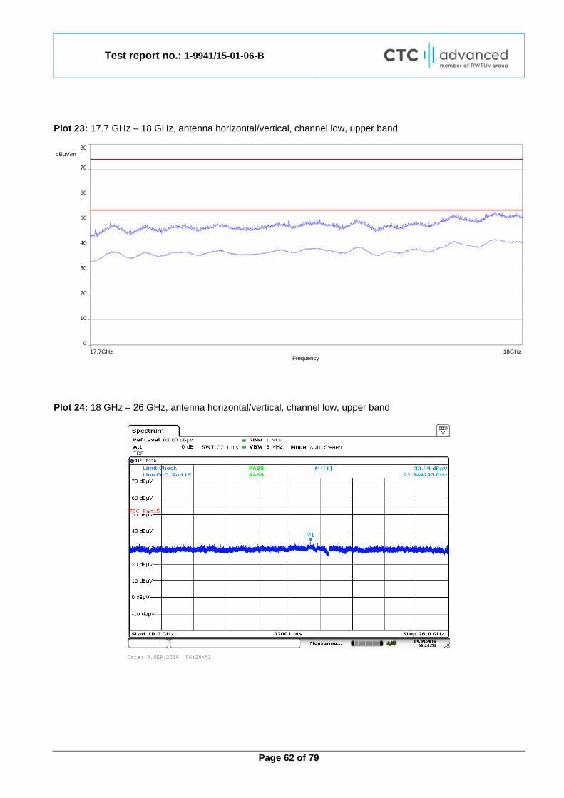
Plot 23: 17.7 GHz – 18 GHz, antenna horizontal/vertical, channel low, upper band
Plot 24: 18 GHz – 26 GHz, antenna horizontal/vertical, channel low, upper band
17.7GHz 18GHzFrequency
0
80 dBµV/m
50
20
70
40
10
60
30
Date: 9.SEP.2016 06:28:51
Test report no.: 1-9941/15-01-06-B
Page 63 of 79
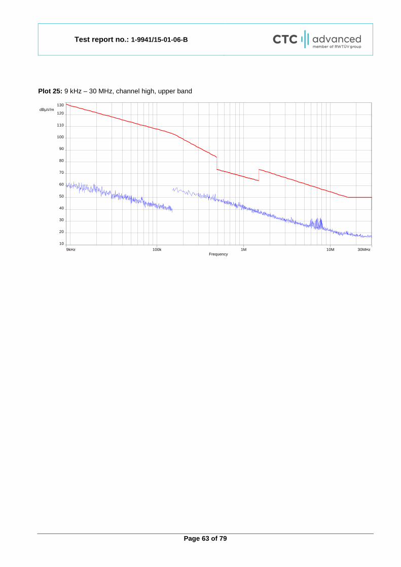
Plot 25: 9 kHz – 30 MHz, channel high, upper band
9kHz 30MHz10M1M100kFrequency
10
130 dBµV/m
120
90
60
30
110
80
50
20
100
70
40

Test report no.: 1-9941/15-01-06-B
Page 64 of 79
Plot 26: 30 MHz – 1 GHz, channel high, upper band
Final_Result:
Frequency (MHz)
QuasiPeak (dBµV/m)
Limit (dBµV/m)
Margin (dB)
Meas. Time (ms)
Bandwidth (kHz)
Height (cm) Pol Azimuth
(deg) Corr. (dB)
35.701950 11.03 30.00 18.97 1000.0 120.000 101.0 H 261.0 13.8 38.707800 15.14 30.00 14.86 1000.0 120.000 101.0 V 280.0 14.0 46.078200 11.63 30.00 18.37 1000.0 120.000 100.0 V 280.0 13.6
685.283100 18.96 36.00 17.04 1000.0 120.000 170.0 H 170.0 21.4 772.858350 20.05 36.00 15.95 1000.0 120.000 170.0 V 81.0 22.7 891.731850 21.48 36.00 14.52 1000.0 120.000 101.0 V 81.0 24.0
0
10
20
30
40
50
60
70
80
30M 50 60 80 100M 200 300 400 500 800 1,05G
Leve
l in
dBµV
/m
Frequency in Hz
FCC_10m_B
Test report no.: 1-9941/15-01-06-B
Page 65 of 79
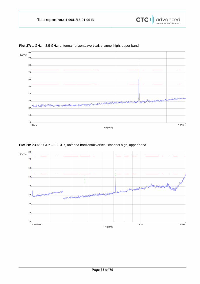
Plot 27: 1 GHz – 3.5 GHz, antenna horizontal/vertical, channel high, upper band
Plot 28: 2392.5 GHz – 18 GHz, antenna horizontal/vertical, channel high, upper band
1GHz 3.5GHzFrequency
0
100 dBµV/m
80
50
20
70
40
10
90
60
30
2.3925GHz 18GHz10GFrequency
0
80 dBµV/m
50
20
70
40
10
60
30
Test report no.: 1-9941/15-01-06-B
Page 66 of 79
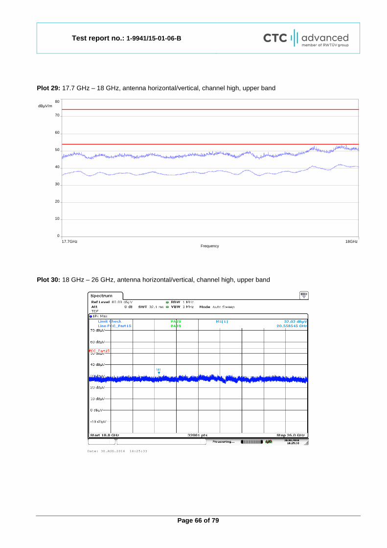
Plot 29: 17.7 GHz – 18 GHz, antenna horizontal/vertical, channel high, upper band
Plot 30: 18 GHz – 26 GHz, antenna horizontal/vertical, channel high, upper band
17.7GHz 18GHzFrequency
0
80 dBµV/m
50
20
70
40
10
60
30
Date: 30.AUG.2016 16:25:33

Test report no.: 1-9941/15-01-06-B
Page 67 of 79
12.6 Receiver unwanted radiation (radiated) Measurement: Measurements were made in accordance with the procedure detailed in KDB 550499 section D2.
Measurement parameter
Detector: Prescan: Peak Final: QPK below 960 MHz RMS above 960 MHz
Video bandwidth:
9 kHz – 150 kHz: 1 kHz 150 kHz – 30 MHz: 30 kHz 30 MHz – 1 GHz: 300 kHz 1 GHz – 26 GHz: 3 MHz
Resolution bandwidth:
9 kHz – 150 kHz: 200 Hz 150 kHz – 30 MHz: 9 kHz 30 MHz – 1 GHz: 100 kHz 1 GHz – 26 GHz: 1 MHz
Span: See plots Trace mode: Max Hold Test setup: See sub clause 7.1 – A & 7.2 – A & 7.3 – A Measurement uncertainty: See sub clause 9
Limits:
FCC IC
47 CFR § 15.109 -/-
Receiver unwanted radiation (radiated)
Frequency (MHz) Field strength (µV/m) 1 Measurement distance (m)
30 - 88 100 (40 dBµV/m) 3 30 - 88 31.6 (30 dBµV/m) 10 88 - 216 150 (43.5 dBµV/m) 3 88 - 216 47.3 (33.5 dBµV/m) 10 216 - 960 200 (46 dBµV/m) 3 216 - 960 63.1 (36 dBµV/m) 10 above 960 500 (54 dBµV/m) 3
1 Measurements in the 9 to 90 kHz, 110 to 490 kHz and above 1000 MHz ranges employ an average detector. Otherwise a quasi-peak detector is used.
Test report no.: 1-9941/15-01-06-B
Page 68 of 79
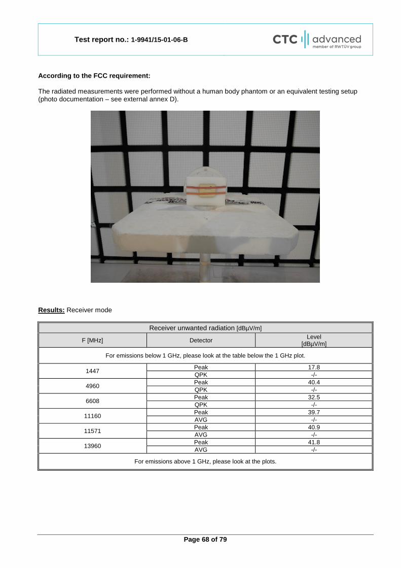
According to the FCC requirement: The radiated measurements were performed without a human body phantom or an equivalent testing setup (photo documentation – see external annex D).
Results: Receiver mode
Receiver unwanted radiation [dBµV/m]
F [MHz] Detector Level [dBµV/m]
For emissions below 1 GHz, please look at the table below the 1 GHz plot.
1447 Peak 17.8 QPK -/-
4960 Peak 40.4 QPK -/-
6608 Peak 32.5 QPK -/-
11160 Peak 39.7 AVG -/-
11571 Peak 40.9 AVG -/-
13960 Peak 41.8 AVG -/-
For emissions above 1 GHz, please look at the plots.

Test report no.: 1-9941/15-01-06-B
Page 69 of 79
Plot: Plot 1: 30 MHz – 1 GHz
Final_Result:
Frequency (MHz)
QuasiPeak (dBµV/m)
Limit (dBµV/m)
Margin (dB)
Meas. Time (ms)
Bandwidth (kHz)
Height (cm) Pol Azimuth
(deg) Corr. (dB)
35.809500 11.43 30.00 18.57 1000.0 120.000 98.0 V 260.0 13.8 42.381450 12.10 30.00 17.90 1000.0 120.000 101.0 V 170.0 14.0 48.894000 9.35 30.00 20.65 1000.0 120.000 101.0 V -9.0 12.9
644.932050 18.51 36.00 17.49 1000.0 120.000 101.0 H 280.0 21.1 729.390900 19.77 36.00 16.23 1000.0 120.000 98.0 H 280.0 22.2 853.422900 21.01 36.00 14.99 1000.0 120.000 101.0 H 261.0 23.5
0
10
20
30
40
50
60
70
80
30M 50 60 80 100M 200 300 400 500 800 1,05G
Leve
l in
dBµV
/m
Frequency in Hz
FCC_10m_B
Test report no.: 1-9941/15-01-06-B
Page 70 of 79
Plot 2: 1 GHz – 18 GHz, antenna horizontal/vertical
Plot 3: 17.7 GHz – 18 GHz, antenna horizontal/vertical
1GHz 18GHz10GFrequency
0
80 dBµV/m
50
20
70
40
10
60
30
17.7GHz 18GHzFrequency
0
80 dBµV/m
50
20
70
40
10
60
30
Test report no.: 1-9941/15-01-06-B
Page 71 of 79
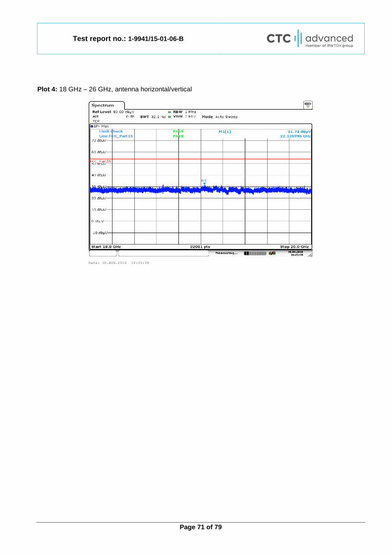
Plot 4: 18 GHz – 26 GHz, antenna horizontal/vertical
Date: 30.AUG.2016 16:25:58
Test report no.: 1-9941/15-01-06-B
Page 72 of 79
12.7 Connection interrupt test (body-worn sensor) Measurement: (a) Establish a LAN connection between the MBAN P/C device and the simulated control point.
(b) Establish connection between the MBAN P/C and the body-worn sensor device under test (DUT).
(c) Configure the control message to enable operation in the 2360−2390 MHz band.
(d) Verify that transmissions between DUT and its associated MBAN P/C are consistent with the control message configuration.
(e) Interrupt the RF and verify that the DUT ceases transmission in the 2360−2390 MHz band with a latency period not exceeding the maximum control message periodicity as specified in the operational description of the device. Additionally, if the DUT operating frequency is now moved to 2390−2400 MHz band verify the channel transition time (latency) is less than the maximum control message periodicity as specified in the operational description of the device.
Measurement parameter Detector: Peak Resolution bandwidth: 1 MHz Video bandwidth: 3 MHz Span: See plots (both MBAN bands) Trace mode: Max Hold Test setup: See sub clause 7.5 – A
Test report no.: 1-9941/15-01-06-B
Page 73 of 79
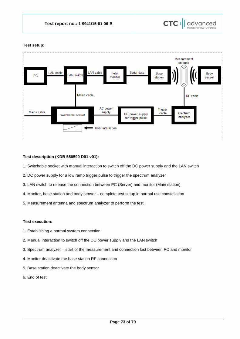
Test setup:
Test description (KDB 550599 D01 v01): 1. Switchable socket with manual interaction to switch off the DC power supply and the LAN switch 2. DC power supply for a low ramp trigger pulse to trigger the spectrum analyzer 3. LAN switch to release the connection between PC (Server) and monitor (Main station) 4. Monitor, base station and body sensor – complete test setup in normal use constellation 5. Measurement antenna and spectrum analyzer to perform the test Test execution: 1. Establishing a normal system connection 2. Manual interaction to switch off the DC power supply and the LAN switch 3. Spectrum analyzer – start of the measurement and connection lost between PC and monitor 4. Monitor deactivate the base station RF connection 5. Base station deactivate the body sensor 6. End of test

Test report no.: 1-9941/15-01-06-B
Page 74 of 79
Step 1 (KDB 550599 D01 v01): (a) Establish a LAN connection between the MBAN P/C device and the simulated control point.
(b) Establish connection between the MBAN P/C and the body-worn sensor device under test (DUT).
Plot 1:
The plot shows the communication of the control message between the MBAN P/C and the body-worn sensor in the 2390-2400 MHz band (Marker 1 @ 2397 MHz). The V1 frequency line marks the end of lower and the start of the upper MBAN band.
Test report no.: 1-9941/15-01-06-B
Page 75 of 79
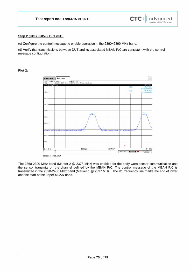
Step 2 (KDB 550599 D01 v01): (c) Configure the control message to enable operation in the 2360−2390 MHz band.
(d) Verify that transmissions between DUT and its associated MBAN P/C are consistent with the control message configuration.
Plot 2:
The 2360-2390 MHz band (Marker 2 @ 2378 MHz) was enabled for the body-worn sensor communication and the sensor transmits on the channel defined by the MBAN P/C. The control message of the MBAN P/C is transmitted in the 2390-2400 MHz band (Marker 1 @ 2397 MHz). The V1 frequency line marks the end of lower and the start of the upper MBAN band.
Test report no.: 1-9941/15-01-06-B
Page 76 of 79
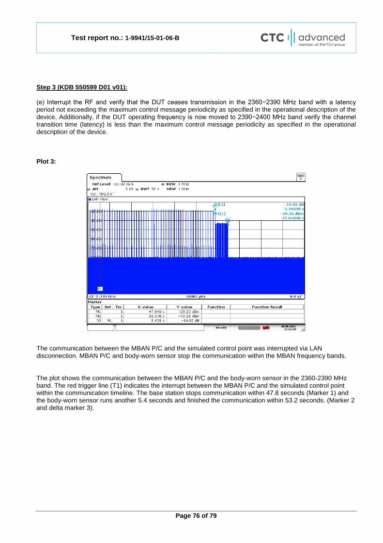
Step 3 (KDB 550599 D01 v01): (e) Interrupt the RF and verify that the DUT ceases transmission in the 2360−2390 MHz band with a latency period not exceeding the maximum control message periodicity as specified in the operational description of the device. Additionally, if the DUT operating frequency is now moved to 2390−2400 MHz band verify the channel transition time (latency) is less than the maximum control message periodicity as specified in the operational description of the device. Plot 3:
The communication between the MBAN P/C and the simulated control point was interrupted via LAN disconnection. MBAN P/C and body-worn sensor stop the communication within the MBAN frequency bands. The plot shows the communication between the MBAN P/C and the body-worn sensor in the 2360-2390 MHz band. The red trigger line (T1) indicates the interrupt between the MBAN P/C and the simulated control point within the communication timeline. The base station stops communication within 47.8 seconds (Marker 1) and the body-worn sensor runs another 5.4 seconds and finished the communication within 53.2 seconds. (Marker 2 and delta marker 3).
Test report no.: 1-9941/15-01-06-B
Page 77 of 79
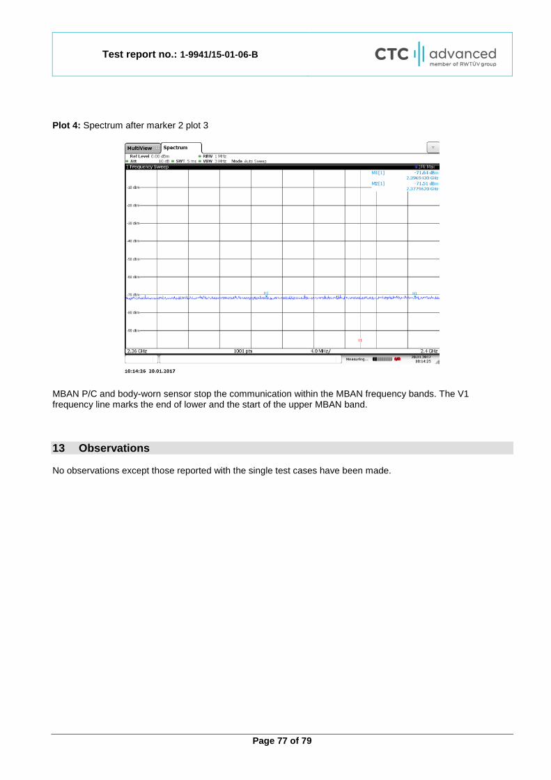
Plot 4: Spectrum after marker 2 plot 3
MBAN P/C and body-worn sensor stop the communication within the MBAN frequency bands. The V1 frequency line marks the end of lower and the start of the upper MBAN band. 13 Observations No observations except those reported with the single test cases have been made.
Test report no.: 1-9941/15-01-06-B
Page 78 of 79
Annex A Glossary
EUT Equipment under test DUT Device under test UUT Unit under test ETSI European Telecommunications Standard Institute
EN European Standard FCC Federal Communication Commission
FCC ID Company Identifier at FCC IC Industry Canada
PMN Product marketing name HMN Host marketing name HVIN Hardware version identification number FVIN Firmware version identification number EMC Electromagnetic Compatibility HW Hardware SW Software
Inv. No. Inventory number S/N or SN Serial number
C Compliant NC Not compliant NA Not applicable NP Not performed PP Positive peak QP Quasi peak
AVG Average OC Operating channel
OCW Operating channel bandwidth OBW Occupied bandwidth OOB Out of band DFS Dynamic frequency selection CAC Channel availability check
OP Occupancy period NOP Non occupancy period
DC Duty cycle PER Packet error rate CW Clean wave MC Modulated carrier
WLAN Wireless local area network RLAN Radio local area network DSSS Dynamic sequence spread spectrum OFDM Orthogonal frequency division multiplexing FHSS Frequency hopping spread spectrum
Test report no.: 1-9941/15-01-06-B
Page 79 of 79
Annex B Document history
Version Applied changes Date of release
-/- Initial release 2016-10-06
A Added chapter 2017-08-16
B Editorial changes, plots of the output power measurements added 2017-09-05
Annex C Accreditation Certificate
first page last page
Note: The current certificate including annex is published on the website (link see below) of the Accreditation Body DAkkS or may be received by CTC advanced GmbH on request http://www.dakks.de/as/ast/d/D-PL-12076-01-01.pdf http://www.dakks.de/as/ast/d/D-PL-12076-01-02.pdf