feasibility of determining aerodynamic coefficients for a
TRANSCRIPT

Feasibility of Determining Aerodynamic Coefficients for a
NASA Apollo Body With the Use of Telemetry Data From Free Flight Range Testing
by Benjamin Topper, T. Gordon Brown, Edward Bukowski, Bradford S.
Davis, Rex A. Hall, Peter C. Muller, Timothy T. Vong, and Fred J. Brandon
ARL-TR-4271 September 2007 Approved for public release; distribution is unlimited.
NOTICES
Disclaimers The findings in this report are not to be construed as an official Department of the Army position unless so designated by other authorized documents. Citation of manufacturer’s or trade names does not constitute an official endorsement or approval of the use thereof. DESTRUCTION NOTICE⎯Destroy this report when it is no longer needed. Do not return it to the originator.

Army Research Laboratory Aberdeen Proving Ground, MD 21005-5069
ARL-TR-4271 September 2007
Feasibility of Determining Aerodynamic Coefficients for a
NASA Apollo Body With the Use of Telemetry Data From Free Flight Range Testing
Benjamin Topper
Data Matrix Solutions, Inc.
T. Gordon Brown, Edward Bukowski, Bradford S. Davis, Rex A. Hall, Peter C. Muller, and Timothy T. Vong
Weapons and Materials Research Directorate, ARL
Fred J. Brandon Dynamic Science, Inc.
Approved for public release; distribution is unlimited.

ii
REPORT DOCUMENTATION PAGE Form Approved OMB No. 0704-0188
Public reporting burden for this collection of information is estimated to average 1 hour per response, including the time for reviewing instructions, searching existing data sources, gathering and maintaining the data needed, and completing and reviewing the collection information. Send comments regarding this burden estimate or any other aspect of this collection of information, including suggestions for reducing the burden, to Department of Defense, Washington Headquarters Services, Directorate for Information Operations and Reports (0704-0188), 1215 Jefferson Davis Highway, Suite 1204, Arlington, VA 22202-4302. Respondents should be aware that notwithstanding any other provision of law, no person shall be subject to any penalty for failing to comply with a collection of information if it does not display a currently valid OMB control number. PLEASE DO NOT RETURN YOUR FORM TO THE ABOVE ADDRESS.
1. REPORT DATE (DD-MM-YYYY)
September 2007
2. REPORT TYPE
Final 3. DATES COVERED (From - To)
5a. CONTRACT NUMBER
5b. GRANT NUMBER
4. TITLE AND SUBTITLE Feasibility of Determining Aerodynamic Coefficients for a NASA Apollo Body With the Use of Telemetry Data From Free Flight Range Testing
5c. PROGRAM ELEMENT NUMBER
5d. PROJECT NUMBER
1L162618AH80
5e. TASK NUMBER
6. AUTHOR(S) Benjamin Topper (DMSI); T. Gordon Brown, Edward Bukowski, Bradford S. Davis, Rex A. Hall, Peter C. Muller, and Timothy T. Vong (all of ARL); Fred J. Brandon (DSI)
5f. WORK UNIT NUMBER
7. PERFORMING ORGANIZATION NAME(S) AND ADDRESS(ES)
U.S. Army Research Laboratory Weapons and Materials Research Directorate Aberdeen Proving Ground, MD 21005-5069
8. PERFORMING ORGANIZATION REPORT NUMBER ARL-TR-4271
10. SPONSOR/MONITOR'S ACRONYM(S) 9. SPONSORING/MONITORING AGENCY NAME(S) AND ADDRESS(ES)
11. SPONSOR/MONITOR'S REPORT NUMBER(S)
12. DISTRIBUTION/AVAILABILITY STATEMENT Approved for public release; distribution is unlimited.
13. SUPPLEMENTARY NOTES
14. ABSTRACT The U.S. Army Research Laboratory (ARL) was requested by the National Aeronautics and Space Administration’s (NASA’s) Langley Research Center to perform a free-flight experiment with telemetry (TM) instrumented sub-scaled re-entry vehicle in order to determine the feasibility of using TM to obtain aerodynamic coefficients. NASA’s current ability to collect aerodynamics data of subscale re-entry vehicles has been limited to forced oscillation wind tunnel testing with a sting-mounted model or by free-flight testing in an indoor aeroballistic range. Both testing techniques have shortcomings. The presence of a rear sting and its effect on the capsule’s aft-body flow field introduce uncer-tainties in forced oscillation test results, and aeroballistic testing provides a very limited set of data and relies on the ability to accurately measure small changes in the capsule’s angle of attack, based on shadowgraph images. The current methods also limit NASA’s abilities to test crew exploration vehicle (CEV) geometry variations such as offsetting the center of gravity and non-symmetrical mass distributions. ARL developed and demonstrated a unique experimental technique to capture the flight dynamics of sub-scaled re-entry vehicles while testing on an exterior ballistics range. This technique combines the gun launch of a projectile that uses a double-length 120-mm gun with an instrumentation package contained inside the re-entry vehicle. For the current phase 1 effort being described, a reduced size Apollo (see figure 1) shaped re-entry vehicle was used because of its similarity to the current CEV being proposed and the existence of vast empirical data available to validate this technique. Following muzzle exit, the sabot is discarded and an ARL-developed constellation of inertial and magnetic sensors generate raw data that is telemetered and captured via a ground station. The data are then fed into a custom analysis tool that fuses the various sources, reconstructs the dynamic motion, and extracts the aerodynamic coefficients. ARL has been successfully employing this technique of using free-flight TM data to extract aerodynamics coefficients on numerous current and past Department of Defense munitions programs. Upon successful validation of this technique, NASA foresees employing ARL telemetry technology as an integral tool for its goal to develop an Orion Crew Exploration Vehicle and other re-entry vehicles as part of Project Constellation. 15. SUBJECT TERMS
aerodynamics; coefficients; free flight; NASA Apollo; telemetry
16. SECURITY CLASSIFICATION OF: 19a. NAME OF RESPONSIBLE PERSON Timothy T. Vong
a. REPORT Unclassified
b. ABSTRACT Unclassified
c. THIS PAGE Unclassified
17. LIMITATIONOF ABSTRACT
SAR
18. NUMBER OF PAGES
25 19b. TELEPHONE NUMBER (Include area code)
410-306-0643
Standard Form 298 (Rev. 8/98) Prescribed by ANSI Std. Z39.18

iii
Contents
List of Figures iv
Acknowledgments v
1. Introduction 1
2. Experiment Description 3 2.1 Vehicle Description.........................................................................................................3 2.2 TM Module Description..................................................................................................5 2.3 Experiment Setup ............................................................................................................6
3. Experimental Results and Analysis 9 3.1 Analytical Methodology................................................................................................10 3.2 EXTRACTR Results .....................................................................................................11
4. Conclusions 13
5. References 15
Distribution List 16
iv
List of Figures
Figure 1. NASA Apollo crew exploration vehicle (1966)............................................................. 1 Figure 2. Example of shadowgraph image. ................................................................................... 3 Figure 3. Example of a wind tunnel sting mount........................................................................... 2 Figure 4. Zero-degree Apollo CEV sabot. ..................................................................................... 3 Figure 5. Fifteen-degree Apollo CEV sabot. ................................................................................. 3 Figure 6. Instrumented CEV round components. .......................................................................... 4 Figure 7. Apollo CEV launch package. ......................................................................................... 4 Figure 8. Apollo CEV TM module cutaway view......................................................................... 5 Figure 9. Accelerometer calibration setup. .................................................................................... 6 Figure 10. Rate sensor calibration setup. ....................................................................................... 7 Figure 11. Magnetometer calibration setup. .................................................................................. 6 Figure 12. Double travel 120-mm cannon. .................................................................................... 7 Figure 13. Flight follower camera. ................................................................................................ 8 Figure 14. Telemetry van exterior. ................................................................................................ 9 Figure 15. Telemetry van interior. ................................................................................................. 8 Figure 16. Dish antenna for telemetry data acquisition. ................................................................ 8 Figure 17. Coordinate system for Apollo CEV. ............................................................................ 9 Figure 18. Total angle of attack for CEV4. ................................................................................. 11 Figure 19. Radar velocity for CEV4. ........................................................................................... 12 Figure 20. Magnetometer angle for CEV4. ................................................................................. 12 Figure 21. Accelerometer k for CEV4......................................................................................... 13 Figure 22. Angular rate r for CEV4. ............................................................................................ 13

v
Acknowledgments
The authors gratefully acknowledge the following people for their important technical contributions:
From NASA Langley Research Center:
James Corliss, Mark Schoenenberger, Ellen Carpenter, and George Sydnor for their planning, programmatic, and decision-making support, in addition to providing the impetus and funding for this program.
From Arrow Tech Associates:
Wayne Hathaway for performing the aerodynamic and flight dynamic analysis of the reduced in-flight data using EXTRACTR1 software package.
From the U.S. Army Aberdeen Test Center:
Walt Zdon and Dave Dawson for providing tracking radar support;
Ken McMullen, for leading the on-site telemetry acquisition support team.
From the U.S. Army Research Laboratory:
Bernard Guidos for coordinating the pre-test ballistics preparations and for serving as the on-site test engineer;
Transonic Experimental Facility technicians John Heath, Barry Hudler, Ken Willan, and Eric Miller for thorough and timely conduct of the firings.
Aaron Rodgers (Data Matrix Solutions, Inc., contractor in support of ARL) and Kenneth Pugh (Dynamic Science, Inc., contractor in support of ARL) for population, assembly, and calibration support on the telemetry electronics.
Philip Peregino for technical review of the report manuscript.
1Extending Telemetry Reduction to Aerodynamic Coefficients and Trajectory Reconstruction.

vi
INTENTIONALLY LEFT BLANK

1
1. Introduction
Project Constellation was launched in response to President Bush’s speech at National Aeronautics and Space Administration (NASA) Headquarters on January 14, 2004, in which he set forth an aggressive plan for future space exploration. NASA plans to develop a new fleet of vehicles with extended capabilities in order to travel to the moon, to Mars, and beyond (1). One of the main challenges of this bold vision is the development of a new crew exploration vehicle to house the astronauts during their missions. The crew exploration vehicle (CEV) being developed is similar to the shape and function of the 1966 Apollo (see figure 1); however, it is three times its size and can transport as many as four astronauts to the moon at a time. Achieving these ambitious goals will require NASA to focus on new technologies and methodologies. The use of the capabilities developed by the U.S. Army Research Laboratory (ARL) to provide data on the aerodynamic forces and moments experienced by a body in free flight is a clear example of NASA’s willingness to adapt and work with other organizations who are leading technological advancement in their respective fields.
Figure 1. NASA Apollo crew exploration vehicle (1966).
ARL has investigated instrumented developmental munitions with custom telemetry (TM) systems to obtain aerodynamic coefficients for the past 40 years. At first, the angular measurements deter-mined from ARL’s TM systems were combined with ground radar velocity measurements and processed with Arrow Tech Associates’ aerodynamic prediction codes to determine stability characteristics and to obtain certain aerodynamic force and moment coefficients (2). Next, ARL and Arrow Tech successfully applied these techniques to a 2.75-inch rocket in order to determine drag, static moment, and roll moment coefficients (3, 4). These projectiles have used a large array of sensors, transmission devices, and novel data measurement techniques that allow the body

2
forces and body rates to be calculated accurately from launch through impact (5). Recently, ARL has partnered with Arrow Tech Associates to develop a custom software program to use the TM data, along with other information available, to calculate the aerodynamic coefficients of a projec-tile from measured flight data (6). This software code, Extending Telemetry Reduction to Aero-dynamic Coefficients and Trajectory Reconstruction (EXTRACTR), imports the sensor data, meteorological (MET) data, radar data, and projectile physical properties to process, through an iterative algorithm, a solution for the aerodynamic coefficients which would have caused the measured flight response. The code attempts to fit the measured translational and rotational sensor data to the six-degree-of-freedom (6-DOF) equations of motion with the use of the maximum likelihood method and least squares and reaches an acceptable solution for a given aerodynamic coefficient (usually within three or four iterations). It was the goal of this program to extend the capability of EXTRACTR to determine the aerodynamic coefficients for a projectile shaped like a NASA CEV, which will experience minimal spin. In particular, the nonlinear coefficients were of great interest to NASA.
NASA has many other ways of estimating aerodynamic coefficients. In the past, NASA has used a combination of spark range and wind tunnel testing. Both have their shortcomings. Spark range testing is taken at an indoor spark range where measurements are made from shadowgraphs (see figure 2) placed along the range. The measured translation and orientation of the projectile are recorded and fit via a similar method as described for EXTRACTR (7 through 9). The limitation of spark range data is that they are only taken at a few discrete points along the flight path, and the body must fly relatively straight in order to avoid damaging the indoor range. Wind tunnel testing is capable of simulating a wide variety of flow regimes and flight conditions with the ability to sustain the loading environment for as long as desired. However, the interference of sting mounts in the flow regime and reduction in the degrees of freedom make it a less ideal environment for collecting pure flight response data. A typical sting mount is shown in figure 3. Computer simulations and computational fluid dynamic (CFD) codes are also available. First and foremost, computer simula-tions or CFD can never fully replace the vital role that measured experimental data have in the process of aerodynamic evaluation. With that in mind, the best packages, such as Arrow Tech’s Projectile Design and Analysis Software (PRODAS), use empirical databases of model geometry and coefficients from previous spark range data for validation. The computer attempts to make the best fit, given the user’s input geometry, physical characteristics, and flight conditions. This tech-nique is severely limited in this case because the Apollo geometry is unique and not similar to anything that would be in these databases.
Figure 2. Example of shadowgraph image. Figure 3. Example of a wind tunnel sting mount.
3
2. Experiment Description
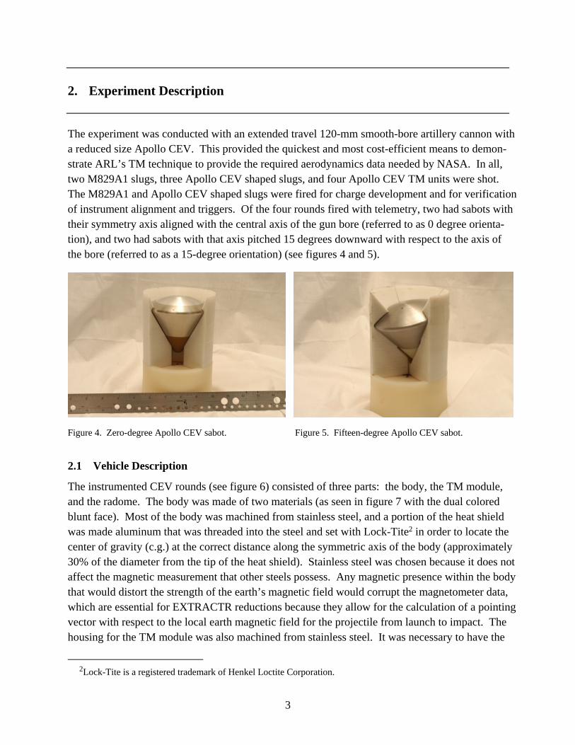
The experiment was conducted with an extended travel 120-mm smooth-bore artillery cannon with a reduced size Apollo CEV. This provided the quickest and most cost-efficient means to demon-strate ARL’s TM technique to provide the required aerodynamics data needed by NASA. In all, two M829A1 slugs, three Apollo CEV shaped slugs, and four Apollo CEV TM units were shot. The M829A1 and Apollo CEV shaped slugs were fired for charge development and for verification of instrument alignment and triggers. Of the four rounds fired with telemetry, two had sabots with their symmetry axis aligned with the central axis of the gun bore (referred to as 0 degree orienta-tion), and two had sabots with that axis pitched 15 degrees downward with respect to the axis of the bore (referred to as a 15-degree orientation) (see figures 4 and 5).
Figure 4. Zero-degree Apollo CEV sabot. Figure 5. Fifteen-degree Apollo CEV sabot.
2.1 Vehicle Description
The instrumented CEV rounds (see figure 6) consisted of three parts: the body, the TM module, and the radome. The body was made of two materials (as seen in figure 7 with the dual colored blunt face). Most of the body was machined from stainless steel, and a portion of the heat shield was made aluminum that was threaded into the steel and set with Lock-Tite2 in order to locate the center of gravity (c.g.) at the correct distance along the symmetric axis of the body (approximately 30% of the diameter from the tip of the heat shield). Stainless steel was chosen because it does not affect the magnetic measurement that other steels possess. Any magnetic presence within the body that would distort the strength of the earth’s magnetic field would corrupt the magnetometer data, which are essential for EXTRACTR reductions because they allow for the calculation of a pointing vector with respect to the local earth magnetic field for the projectile from launch to impact. The housing for the TM module was also machined from stainless steel. It was necessary to have the
2Lock-Tite is a registered trademark of Henkel Loctite Corporation.

4
radome machined from plastic that would allow for the telemetered data from the antenna to be transmitted through it. The TM was threaded into the body until it reached a stopping point. The radome was threaded onto a smaller diameter thread around the transmitter and antenna on the aft end of the TM housing until it made contact with the body.
Figure 6. Instrumented CEV round components.
The sabot design was selected with the goals of time, flexibility, and cost efficiency in mind. The sabots (four petals total), made of polycarbonate, were rapidly prototyped from a fused deposition modeling (FDM) machine. This particular machine was capable of building the sabot in fewer than 8 hours. Because of the layering process that the FDM machine uses to build a part, the sabots were capable of assuming any shape, and it was possible to rotate the accepting vehicle at any angle within the sabot. A tapered nylon obturator plate sat behind the sabot. Its purpose was to hold the base of the sabot together in the tube and to create a seal during launch. The CEV launch package components are shown in figure 7.
Figure 7. Apollo CEV launch package.
5
2.2 TM Module Description
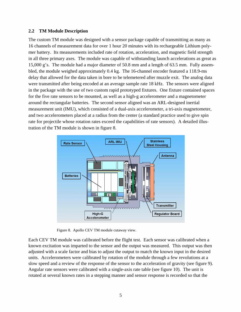
The custom TM module was designed with a sensor package capable of transmitting as many as 16 channels of measurement data for over 1 hour 20 minutes with its rechargeable Lithium poly-mer battery. Its measurements included rate of rotation, acceleration, and magnetic field strength in all three primary axes. The module was capable of withstanding launch accelerations as great as 15,000 g’s. The module had a major diameter of 50.8 mm and a length of 63.5 mm. Fully assem-bled, the module weighed approximately 0.4 kg. The 16-channel encoder featured a 118.9-ms delay that allowed for the data taken in bore to be telemetered after muzzle exit. The analog data were transmitted after being encoded at an average sample rate 18 kHz. The sensors were aligned in the package with the use of two custom rapid prototyped fixtures. One fixture contained spaces for the five rate sensors to be mounted, as well as a high-g accelerometer and a magnetometer around the rectangular batteries. The second sensor aligned was an ARL-designed inertial measurement unit (IMU), which consisted of a dual-axis accelerometer, a tri-axis magnetometer, and two accelerometers placed at a radius from the center (a standard practice used to give spin rate for projectile whose rotation rates exceed the capabilities of rate sensors). A detailed illus-tration of the TM module is shown in figure 8.
Figure 8. Apollo CEV TM module cutaway view.
Each CEV TM module was calibrated before the flight test. Each sensor was calibrated when a known excitation was imparted to the sensor and the output was measured. This output was then adjusted with a scale factor and bias to adjust the output to match the known input in the desired units. Accelerometers were calibrated by rotation of the module through a few revolutions at a slow speed and a review of the response of the sensor to the acceleration of gravity (see figure 9). Angular rate sensors were calibrated with a single-axis rate table (see figure 10). The unit is rotated at several known rates in a stepping manner and sensor response is recorded so that the

6
correct scale factor and bias can be applied to the sensor. Data taken during this step were used to calibrate the axial offset (AO) accelerometers on the IMU. Finally, magnetometers were calibrated with a Helmholtz coil (see figure 11). The coil generates a pre-set array of magnetic fields of dif-ferent magnitudes and orientations which will characterize the response of the magnetometers in the TM module. Following sensor calibration, physical measurements were taken. The mass, c.g., and mass moments of inertia were measured with instrumentation at ARL’s transonic experimental facility (TEF).
Figure 9. Accelerometer calibration setup.
Figure 10. Rate sensor calibration setup. Figure 11. Magnetometer calibration setup.
2.3 Experiment Setup
The experiment was performed at the TEF at Aberdeen Proving Ground, Maryland, on April 26-27, 2006. A double travel 120-mm smooth-bore cannon, shown in figure 12, was used to launch the rounds. An extended travel barrel (approximately 8.8 meters long) can increase the muzzle velocity approximately 20% without increasing the launch accelerations to the launch package when compared to a single length barrel. It was important to maximize the muzzle velocity of the

7
NASA Apollo CEV so that data could be obtained through the highest Mach numbers. The quadrant elevation of the gun was set to 45 degrees. Piezoelectric pressure probes provided pressure measurements at the breech and at a point halfway down the gun. Peak pressure was also measured by copper crusher gauges. A Weibel tracking radar with a tracking antenna provided measurements of the Apollo’s velocity and position as it traveled down range. A stationary radar was aimed at the muzzle to give a more focused measurement of muzzle exit velocity. A MET measurement system was placed near the firing site to provide local conditions, and weather balloons were launched three times each day to monitor conditions higher in the atmosphere.
Figure 12. Double travel 120-mm cannon.
A high speed (flight follower) video camera, capable of panning along the flight path, tracked the projectile from the muzzle through its first 100 ms of flight. This video provided visual verifica-tion of sabot integrity, structural integrity of the projectile, and an indication of the quality of the sabot separation. The importance of this flight follower video was demonstrated in this experiment and is discussed in the results section. The flight follower setup is shown in figure 13. It is positioned along the line of fire, approximately 78 meters down range from the muzzle.
A TM van, operated by Aberdeen Test Center (ATC), was equipped with telemetry data acquisi-tion instrumentation. Three receiving antennas were placed around the firing site with different orientations in order to increase the quality of the data received and to ensure that no data would be lost (see figure 16). All CEV TM data times were stamped with inter-range instrumentation group - time code format B time and time-zero referenced to an infrared (IR) sensor that was pointed at the gun to detect muzzle blast.
8
Figure 13. Flight follower camera.
Figure 14. Telemetry van exterior. Figure 15. Telemetry van interior.
Figure 16. Dish antenna for telemetry data acquisition.

9
3. Experimental Results and Analysis
This report focuses on the data received from the third instrumented Apollo CEV shot (CEV4), which was launched in a 15-degree sabot. The CEV4 data were considered the best set because the CEV4 did not experience any impact from pieces of the sabot or obturator after separation during its flight, thus reducing the risk of tainted aerodynamics data. The CEV flight body recontact issue during flight was verified visually for each CEV from the flight follower video. This recontact issue was resolved in an ensuing sabot redesign program. After data from all three antennas were combined, a master data set was compiled in which no frames of data were lost. The calibration measured before flight was applied to each channel of sensor data. The body-fixed principal axes of the CEV (I, J, and K) and the earth-fixed (X,Y, and Z) were defined (see figure 17).
Figure 17. Coordinate system for Apollo CEV.
Set-back acceleration loads at launch exceeded the range of the axial and radial sensors (9,000 g’s and 300 g’s, respectively). Accelerometers placed at a radial offset from the symmetric axis of the body can be used to calculate the spin rate. This technique is not as accurate when the spin rate is not much larger than the yawing rates. The effects of the yawing rate on the accelerometers can be removed if the yawing rate is well known. Angular rate sensor data were planned for that purpose; however, rate sensors for both the J and K axes were clipped during the flight. The clipping was caused by unexpected motions during flight, which caused the rate sensors to be out of range. With the full effects of the yawing motion included, the accelerometer data calculated a spin rate about 3.5 Hz for the first second of flight.
Angular rate sensors have proved through other ARL munitions test programs to be prone to a loss of data for a short period of time after launch because of the way the sensors operate. It is believed

10
that the vibratory mass system inside the sensor packaging enters a resonance regime caused by the vibrations of gun launch. Based on previous test flight data to 15,000 g’s, the angular rate sensor data for the first 100 to 200 ms of flight will not be considered accurate. The measurement range on some of the rate sensors were also shown to be too low for frequencies encountered during the projectile’s flight. Although the angular rate exceeded the range of the sensors during a part of the flight, a fit of the data yields good comparison to other sensor data and results with EXTRACTR. Analysis of the rate sensors with higher ranges, which did not clip until later in the flight, support a 4-Hz spin rate of the body during the first second of flight.
The magnetometer data collected were excellent. After corrections for scale factor and bias, the data were checked for readings in the gun tube, which confirmed the strength of the earth’s mag-netic field at that point. Processing of the magnetometer data shows large yawing motion but it does not suggest that the body was tumbling. Magnetometer J was processed for magnetic roll rate, which agreed with the angular rate sensor data that the projectile experienced a spin of nearly 4 Hz during the first second of flight.
Information gained by this early processing was used to check against the reconstruction performed by EXTRACTR.
3.1 Analytical Methodology
All parameters are entered in EXTRACTR, including a description of physical characteristics (mass, length, c.g., and moments of inertia), initial aerodynamic prediction (often with the use of PRODAS), MET data, radar data, initial conditions (gun location, quadrant elevation, azimuth), and sensor definition (scale factor, misalignment, cross-axis sensitivity, and location).
EXTRACTR fits measured motion history to 6-DOF equations of motion while iteratively varying aerodynamic coefficients, using a maximum likelihood method, until a match of the motion history is achieved. This fit is accomplished with a window of data at a time attributable to Mach number dependencies. In this manner, a best fit of coefficients is achieved over a large range of Mach numbers.
EXTRACTR analysis is initiated when a model of the projectile that matches its exterior geometry and physical properties (mass, length, c.g., and mass moments of inertia) is entered. At this point, an initial aerodynamic model can be generated via PRODAS. The user is then prompted to enter the test’s initial conditions, including the quadrant elevation, azimuth, initial pitch and yaw angles, initial pitch and yaw rates, and MET data, the position of the radar with respect to the gun, the local earth magnetic field, and the position of the sensors with respect to the c.g., as well as any misalignment or cross-axis sensitivity. Finally, the TM sensor and radar data are entered with the option for the user to eliminate any frames that are deemed to be invalid.
After all the data have been entered, EXTRACTR proceeds to estimate the aerodynamic coeffi-cients. The data are integrated with estimated values of the aerodynamic coefficients and initial
11
conditions from the initial aerodynamic model. Those same equations are then partially differen-tiated for each coefficient that forms a set of parametric equations, which are then numerically integrated to obtain values for the partial derivatives with respect to each coefficient. A differential corrections equation is then set from a Taylor expansion of the dependent variables of the equations of motion. The sensor data are then compared to the computed values in a weighted least squares sense, and corrections are computed for the coefficients and initial conditions. The coefficients are adjusted by these corrections and the process begins again with these new values of the coefficients. The method will iterate until convergence is achieved. It has been shown through experience that convergence should occur by the third or fourth iteration.
3.2 EXTRACTR Results
EXTRACTR software analysis of the experimental data from CEV4 was done to (a) extract the aerodynamic force and moment coefficients, and (b) reconstruct the flight trajectories for the flight segment of interest. The flight segment of interest was from launch down to Mach 0.6, but before the CEV4 rotates through 90 degrees. In other words, the CEVs seemed to tumble after about 1 to 1.5 seconds of flight. CEV4 showed some motion damping very early in the flight, before it exhibited undamped motion for the remainder of the flight. After the data were analyzed to extract relevant aerodynamics including axial force, normal force, pitching moment, and pitch-damping moment, the flight trajectory was reconstructed. The fits to the magnetometer, accelerometer, and angular rate data are considered very good. Figure 18 shows the total angle of attack and Mach number for CEV4 plotted against time. The trajectory reconstruction yielded the following com-parisons of experimental data to EXTRACTR-calculated values shown respectively in figures 19 through 22: the radar velocity, the magnetic pointing angle, acceleration in k direction, and angular rate.
0
10
20
30
40
50
60
0 0.2 0.4 0.6 0.8 1 1.2 1.4 1.6
Time, sec
AO
A, d
eg
0.0
0.5
1.0
1.5
2.0
2.5
3.0
3.5M
ach
No.
AOAMach No.
Figure 18. Total angle of attack for CEV4.
12
0
100
200
300
400
500
600
700
800
900
1000
0.00 0.10 0.20 0.30 0.40 0.50 0.60 0.70 0.80 0.90 1.00 1.10 1.20 1.30 1.40 1.50
Exp_
vs_C
alc_
Rad
_Vel
(m/s
ec)
Exp_vs_Calc_Rad_VelExp_vs_Calc_Rad_Vel
Time (sec)Prodas2000 V3 Arrow Tech AssociatesCEV4_ARL_NASA_RevAA.pr3 08/16/06
ExperimentalCalculated
Figure 19. Radar velocity for CEV4.
80
90
100
110
120
130
140
150
160
170
180
0.00 0.10 0.20 0.30 0.40 0.50 0.60 0.70 0.80 0.90 1.00 1.10 1.20 1.30 1.40 1.50
Exp_
vs_C
alc_
Mag
_Poi
ntin
g (d
eg)
Exp_vs_Calc_Mag_PointingExp_vs_Calc_Mag_Pointing
Time (sec)Prodas2000 V3 Arrow Tech AssociatesCEV4_ARL_NASA_RevAA.pr3 08/16/06
ExperimentalCalculated
Figure 20. Magnetometer angle for CEV4.

13
0
10
20
30
40
50
60
-10
-20
-30
-40
-500.00 0.10 0.20 0.30 0.40 0.50 0.60 0.70 0.80 0.90 1.00 1.10 1.20 1.30 1.40 1.50
Exp_
vs_C
alc_
Acc
el_K
(G)
Exp_vs_Calc_Accel_KExp_vs_Calc_Accel_K
Time (sec)Prodas2000 V3 Arrow Tech AssociatesCEV4_ARL_NASA_RevAA.pr3 08/16/06
ExperimentalCalculated
Figure 21. Accelerometer k for CEV4.
0
10
20
30
40
50
-10
-20
-30
-40
-50
-600.00 0.10 0.20 0.30 0.40 0.50 0.60 0.70 0.80 0.90 1.00 1.10 1.20 1.30 1.40 1.50
Exp_
vs_C
alc_
Ang
_Rat
e_r (
rad/
sec)
Exp_vs_Calc_Ang_Rate_rExp_vs_Calc_Ang_Rate_r
Time (sec)Prodas2000 V3 Arrow Tech AssociatesCEV4_ARL_NASA_RevAA.pr3 08/16/06
ExperimentalCalculated
Figure 22. Angular rate r for CEV4.
4. Conclusions
Based on initial test and data results, it has been shown that it is feasible to determine the aero-dynamic coefficients for a NASA Apollo CEV body with TM data from free flight range testing. During this project, we were able to successfully (a) design and integrate a TM sensor suite within the 120-mm Apollo launch package that survives as much as 15 kilo-g’s, (b) implement a detailed test plan with the proper equipment to enable launch velocities greater than Mach 3.0, and

14
(c) modify calibration procedures, simulations, and analysis techniques to smooth migration of TM data for implementation of EXTRACTR as the integrated analysis system for dynamic flight data. After modification of the EXTRACTR algorithms, the aerodynamics and stability characteristics of the Apollo CEV were successfully extracted from the experimental TM measurements. Recon-struction of the flight dynamics and trajectories showed close agreement with the experimental data measurements. The aerodynamic results varied more from round to round than expected. This large variation is attributed to external interferences with the rounds, mostly from sabot inter-ference. The large angle motion dominated the pitch-damping effect and drove the axial force variations at large angles. Overall, the EXTRACTR analysis closely matched the measured flight dynamics and provided a valuable case study to improve the procedure and analytical capabilities of EXTRACTR for the future.
Future plans for this project include finalizing the aerodynamic coefficient extraction from this experiment and a detailed comparison of TM derived results to historical Apollo data, and using the lessons learned to perform a free flight telemetry experiment with NASA’s Orion CEV. This project is planned as a first in a series to evaluate the usefulness of on-board inertial measure-ments to characterize the aerodynamic characteristics of a NASA re-entry vehicle.
15
5. References
1. Connolly, J. One Step Back, One Giant Leap Forward. Mechanical Engineering Magazine May 2006, 128, 5.
2. Whyte, R. H.; Mermagen, W. R. A Method for Obtaining Aerodynamic Coefficients from Yawsonde and Radar Data; MR-2280; U.S. Army Ballistics Research Laboratory: Aberdeen Proving Ground, MD, March 1973.
3. Brown, T. G.; Brandon, F. J.; Harkins, T. E.; Hathaway, W. Drag and Moment Coefficients Measured During Flight Testing of a 2.75-inch Rocket. 35th Aerospace Sciences Meeting & Exhibit, Reno, NV, AIAA 97-0634, January 1997.
4. Hathaway, A.; Hathaway, W.; Whyte, R.; Davis, B.; Brown, T.; Hepner, D.; Harkins, T. Combining Radar, Yawsonde, and On-Board Telemetry Data to Determine Aerodynamic Coefficients. 51st Aeroballistic Range Association, Madrid, Spain, 18-21 September 2000.
5. Davis, B.; Harkins, T.; Hepner, D.; Patton, B.; Hall, R. Aeroballistic Diagnostic Fuze (DFuze) Measurments for Projectile Development, Test, and Evaluation; ARL-TR-3204; U.S. Army Research Laboratory: Aberdeen Proving Ground, MD,
6. Davis, B.; Hathaway, H.; Hathaway, A.; Thompson, A. Extending Telemetry Reduction to Aerodynamic Coefficients and Trajectory Reconstruction (EXTRACTR) Flight Experiment Using 155-mm M483A1 Projectiles; ARL-TR-3563; U.S. Army Research Laboratory: Aberdeen Proving Ground, MD, August 2005.
7. Hathaway, W.; Whyte, R. Aeroballistic Research Facility Free Flight Data Analysis Using the Maximum Likelihood Method; AFATL-TR-79-98; Eglin Air Force Base, FL, December 1979.
8. Yates, L.; Chapman, G.; Row, C. CADRA: A Comprehensive Aerodynamic Data Reduction System for Aeroballistic Ranges. Eglin Paper 47th ARA Meeting, ISL France, October 1996.
9. Murphy, C. Data Reduction for the Free Flight Spark Ranges; BRL Report 900; U.S. Army Ballistics Research Laboratory: Aberdeen Proving Ground, MD, February 1954.
16
NO. OF COPIES ORGANIZATION 1 DEFENSE TECHNICAL (PDF INFORMATION CTR ONLY) DTIC OCA 8725 JOHN J KINGMAN RD STE 0944 FORT BELVOIR VA 22060-6218 1 US ARMY RSRCH DEV & ENGRG CMD SYSTEMS OF SYSTEMS INTEGRATION AMSRD SS T 6000 6TH ST STE 100 FORT BELVOIR VA 22060-5608 1 DIRECTOR US ARMY RESEARCH LAB IMNE ALC IMS 2800 POWDER MILL RD ADELPHI MD 20783-1197 1 DIRECTOR US ARMY RESEARCH LAB AMSRD ARL CI OK TL 2800 POWDER MILL RD ADELPHI MD 20783-1197 2 DIRECTOR US ARMY RESEARCH LAB AMSRD ARL CS OK T 2800 POWDER MILL RD ADELPHI MD 20783-1197 2 DIR US ARMY RESEARCH LAB ATTN AMSRD ARL SE S J EICKE AMSRD ARL SE SA J PRICE 2800 POWDER MILL RD ADELPHI MD 20783-1197 3 DIR US ARMY RESEARCH LAB ATTN AMSRD ARL SE SS L ADAS A EDELSTEIN D FLIPPEN M D’ONOFRIO 2800 POWDER MILL RD ADELPHI MD 20783-1197 4 CDR US ARMY TACOM ARDEC ATTN AMSRD AAR AEP F(A) W KONICK C ROBINSON D WARD B CHRISTOPHERSON 2800 POWDER MILL RD ADELPHI MD 20783-1197
1 DIR US ARMY RESEARCH LAB ATTN AMSRD ARL WM MB A FRYDMAN 2800 POWDER MILL RD ADELPHI MD 20783-1197 2 CDR US ARMY TACOM ARDEC ATTN AMSRD AAR AEM A T RECCHIA ATTN AMSRD AAR AEM A W TOLEDO BLDG 95 PICATINNY ARSENAL NJ 07806-5000 1 CDR US ARMY TACOM ARDEC ATTN AMSRD AAR AEP M W KOENIG BLDG 95 PICATINNY ARSENAL NJ 07806-5000 1 CDR US ARMY TACOM ARDEC ATTN AMSRD AAR AEP E M S HOLLIS BLDG 94 PICATINNY ARSENAL NJ 07806-5000 1 US ARMY ARDEC ATTN AMSRD AAR AEP E D CARLUCCI BLDG 94 PICATINNY ARSENAL NJ 07806-5000 1 US ARDEC ATTN AMSRD AAR AEM M PALATHINGAL BLDG 65S PICATINNY ARSENAL NJ 07806-5000 1 INST FOR ADVNCD TCHNLGY THE UNIV OF TEXAS AT AUSTIN 3925 W BRAKER LN AUSTIN TX 78759-5316 8 NASA LANGLEY RESEARCH CENTER, MS 489 ATTN: MARK SCHOENENBERGER (5 CYS) ATTN: JAMES CORLISS ATTN: ELLEN CARPENTER ATTN: GEORGR SYDNOR HAMPTON, VA 23681 1 CDR OFC OF NAVAL RSCH ATTN CODE 333 P MORRISSON 800 N QUINCY ST RM 507 ARLINGTON VA 22217-5660 1 CDR NAWC WEAPONS DIV ATTN CODE 543200E G BORGEN BLDG 311 POINT MUGU CA 93042-5000

17
1 PROGRAM MANAGER ITTS PEO-STRI ATTN AMSTI EL D SCHNEIDER 12350 RESEARCH PKWY ORLANDO FL 32826-3276 2 CDR US ARMY RDEC ATTN AMSRD AMR SG SD P JENKINS AMSRD AMR SG SP P RUFFIN BLDG 5400 REDSTONE ARSENAL AL 35898-5247 1 DARPA/MTO ATTN C NGUYEN 3701 N FAIRFAX DR ARLINGTON VA 22203-1714 1 OSD DOT&E R&R ATTN W ATTERBURY 1700 DEFENSE PENTAGON WASHINGTON DC 20301-1700 1 JOHNS HOPKINS UNIV APPLIED PHYSICS LAB ATTN W D’AMICO 1110 JOHNS HOPKINS RD LAUREL MD 20723-6099 1 OFC OF NAVAL RESEARCH ATTN J GOLDWASSER 875 N RANDOLPH ST RM 653 ARLINGTON VA 22203-1927 1 CRD NAVAL RSRCH LAB TECH LIBRARY J BORIS WASHINGTON DC 20375-5000 1 AIR FORCE OFC OF SCI RSCH ATTN M BERMAN SUITE 235 RM 3112 875 N RANDOLPH ST ARLINGTON VA 22203-1768 ABERDEEN PROVING GROUND 1 DIRECTOR US ARMY RSCH LAB ATTN AMSRD ARL CI OK (TECH LIB) BLDG 4600 1 DIRECTOR US ARMY RSCH LABORATORY ATTN AMSRD ARL CI OK (TECH LIB) BLDG 4600
1 DIRECTOR US ARMY RSCH LABORATORY ATTN AMSRD ARL WM SG T ROSENBERGER BLDG 4600 1 DIRECTOR US ARMY RSCH LABORATORY ATTN AMSRD ARL WM B M ZOLTOSKI BLDG 4600 28 DIRECTOR US ARMY RSCH LABORATORY ATTN AMSRD ARL WM BA T BROWN F BRANDON E BUKOWSKI J CONDON B DAVIS D GRZYBOWSKI R HALL T HARKINS D HEPNER K HUBBARD M ILG E IRWIN G KATULKA T KOGLER D LYON J MALEY P MULLER M NAIR B PATTON P PEREGINO D PETRICK K PUGH B TOPPER T VONG (5 CYS) BLDG 4600 7 DIRECTOR US ARMY RSCH LABORATORY ATTN AMSRD ARL WM BC P PLOSTINS B GUIDOS J GARNER J HEATH B HUDLER E MILLER K WILLAN BLDG 4600 1 DIRECTOR US ARMY RSCH LABORATORY ATTN AMSRD ARL WM TC R COATES BLDG 309 1 CDR US ARMY TACOM ARDEC ATTN AMSRD AAR AEF T R LIESKE BLDG 305 3 CDR USAATC ATTN CSTE DTC AT FC S T GARCIA CSTE DTC AT CO J WALLACE CSTE DTC AT FC L R SCHNELL BLDG 400 2 CDR USAATC ATTN CSTE DTC AT AT B K MCMULLEN BLDG 359