feasibility of using a knowledge-based system concept for ... · pdf fileknowledge-based...
TRANSCRIPT

NASA Technical Memorandum 4279 l NASA-TM-4279 19920000799
Feasibility of Using a
Knowledge-Based System
Concept for In-Flight PrimaryFlight Display Research
Wendell R. Ricks Ij j R _ _V _r_._,:_V-1l.-.|kllt#tlt i _k/| I I
i , i i
!
SEPTEMBER 1991 q_P ' )i //
LANGLEYRESEARCHCENTERLIBRARYNASA
HAMPTON,VIRGIh!!Ai ii
https://ntrs.nasa.gov/search.jsp?R=19920000799 2018-05-12T15:07:03+00:00Z


NASA Technical Memorandum 4279
Feasibility of Using a
Knowledge-Based System
Concept for In-Flight PrimaryFlight Display Research
Wendell R. Ricks
Langley Research Center
Hampton, Virginia
NASANational Aeronautics andSpace Administration
Office of ManagementScientific and TechnicalInformation Program1991


Summary led to information-management concerns (e.g., dis-
A study was conducted to determine the fea- play clutter). Research efforts that address these
sibility of using knowledge-based system architec- PFD information-management concerns have been
tures for in-flight research of primary flight display underway at NASA Langley Research Center (refs. 1information-management issues. Results of an earlier and 2). One such effort was exploring the man-study showed knowledge-based programming tech- agement of information on the PFD by dynamicallyniques reduced development problems experienced tailoring the optional information to the task(s) thewhen using traditional programming techniques for pilot performed during flight. This task-tailored ap-workstation research of primary flight display issues, proach to PFD information management was the ap-
plication used for the study described in this paperPlans were then made to use knowledge-based sys-tems for in-flight research. However, the feasibility of and is described in more detail in the project descrip-using knowledge-based systems for in-flight research tion in reference 3.
remained an issue. The feasibility relied on the abil- Each of the research efforts exploring differentity to integrate knowledge-based systems with exist- PFD information-management approaches requireding onboard aircraft systems. And, given the hard- very complex logic to automate. In past efforts,ware and software platforms available for this study, automating different PFD information-managementthe feasibility also depended on the ability to use strategies relied on the ability to implement theinterpreted-LISP software with the real-time oper- complex logic with traditional procedural program-ation of the primary flight display. In addition to ming techniques in compiled computer languagesevaluating these feasibility issues, this study deter- like FORTRAN. With these earlier implementations,mined whether the software-engineering advantages some algorithms (e.g., searches) and some systemof knowledge-based systems found for this applica- characteristics (e.g., explanation) were difficult totion in the earlier workstation study extended to the achieve when using traditional programming meth-in-flight research environment. To investigate these ods. Furthermore, with the complexity of the logicissues, two integrated knowledge-based systems were and the frequent changes that occurred to the re-
designed to control the primary flight display ac- search systems, many software engineering problemscording to preexisting specifications of an ongoing resulted.primary flight display information-management re-search effort. These two knowledge-based systems Most of the software engineering problems re-were implemented onboard the Transport Systems sulted from the frequent changes to system specifi-Research Vehicle Boeing 737 at the Langley Research cations that occur in all research environments. TheCenter to assess the feasibility and software engi- lengthy and involved process necessary to make theneering issues described above. Flight test results changes to the procedural programs, coupled withwere successful in showing the feasibility of using the complex nature of the logic itself, resulted inknowledge-based systems in flight with actual air- systems that were hard to trace, modify, and ver-
craft data. Additionally, the ease and efficiency of ify (ref. 4). These problems would worsen with eachimplementing and maintaining the systems for the change that occurred to the logic in the course of theflight tests confirmed the software engineering advan- research effort.
tages of the knowledge-based system approach for the Since changes to specifications and subsequentlyin-flight research environment, to the code are integral parts of a research system
Acronyms life cycle, software engineering issues are a primarycost and concern. This concern led to the investiga-
DATAC digital autonomous terminal access tion of alternate implementation techniques for thecommunication PFD information-management research efforts. As
an alternative to the traditional procedural approachKBS knowledge-based systemto implementing the PFD information-management
PFD primary flight display logic, a knowledge-based system (KBS) approach was
TSRV Transport Systems Research Vehicle explored. The decision to explore a KBS approachwas based in part on an earlier study that found KBS
Introduction architectures easier to manage than the traditionalarchitecture, given complex logic like that needed for
The amount of information already on the pri- the PFD information-management research (ref. 4).mary flight display (PFD) of a commercial "glass
cockpit" (see fig. 1) and the likelihood of increas- While software engineering successes of KBS ap-ing the amount of information on future PFD's have proaches for workstation research have been well

documented (refs. 5-7), uses of KBS architectures At the time of this study, the systems onboard thefor research in the actual application environments TSRV consisted of a digital flight control system, awere far less common. KBS's and the more general digital navigation and guidance system, and a "glass
category of "rapid prototyping" use a nontraditional cockpit" representation of cockpit information in thesoftware development cycle based on a principle of research flight deck (see fig. 4). The digital flightearly systems development (usually incomplete sys- control system provided both automatic and fly-by-
tems) and easy to make and understand incremental wire control-wheel (stick) steering options. The nav-revisions to the system. KBS architectures are often igation and guidance systems provided position esti-used with rapid prototyping because they provide the mates, flight route definition, guidance commands torich programming environment (e.g., tools for exam- the flight controls, and flight data storage for multipleining declarative knowledge) conducive to rapid pro- navigation purposes. The "glass cockpit" researchtotyping. Even though a few KBS architectures have flight deck presented information to the flight crewbccn taken to their application environment (refs. 8 via eight 8-in-square electronic displays that repre-and 9), using them for in-flight research had not yet sent the technology already available in commercialbeen explored. Therefore, feasibility was a concern transports today (e.g., Boeing 757/767 and Airbuswhen plans were developed to use KBS's for in-flight 320). Systems onboard the TSRV were driven by on-research, board computers and specially developed computer
software. The onboard computers consisted of aSince PFD information-management research us- MicroVAX II, two Nordens (i.e., flight-hardened PDP
ing a KBS architecture was the first study to involve 11/70), GRiD 386-based laptops, and several 8086-KBS's running in LISP (ref. 10) in real time on the and 8088-based processors for the display systems.NASA Langley Boeing 737-100 research aircraft, spe-
cific feasibility questions arose. These questions con- Simulator Descriptioncerned the ability to integrate KBS's with the exist-
Some preliminary work (i.e., knowledge acquisi-ing onboard aircraft systems and the ability to useinterpreted-LISP software for the real-time operation tion and early testing) in this study took place in theof the PFD. In addition, there was the question of TSRV Simulator for the Boeing 737 airplane at thewhether the software engineering advantages found Langley Research Center (see fig. 5). At the timein the workstation environment could transfer to the of this study, the TSRV Simulator was a fixed-base
in-flight research environment, cockpit closely representing the research flight deckof the TSRV aircraft.
These questions were addressed in the study de-The simulation used a full six-degree-of-freedomscribed in this paper to evaluate the use of KBS ar-
chitccturcs for in-flight research of PFD information set of nonlinear equations of motion containing amanagement. The objectives of this study were to de- detailed aerodynamic package, an engine model, asign, implement, and test (in flight) a KBS approach landing gear model, and functional representationsto PFD information management to determine the of the advanced flight control configurations avail-
feasibility of using KBS's as in-flight research tools able to the airplane (with nonlinear models of thefor this application. To address the software engi- servo-actuators). The aerodynamic model incorpo-necring question, an informal evaluation of the ad- rated two- and three-dimensional table look-ups forvantages of the KBS approach for this application aerodynamic coeflicicnts and adjusted these coefi%was done while preparing and maintaining the soft- cients for ground effects. The engine model includedware for flight test. detailed ram air and temperature effects. The land-
ing gear model included provisions for braking and
Research Systems for steering.Processing the simulation equations was done by
Aircraft Description a Control Data Corporation (CDC) CYBER 175 dig-
The study described in this paper used the Trans- ital computer at a 32-Hz iteration rate. A standard-port Systems Research Vehicle (TSRV) Boeing 737 at atmosphere model with no winds was used. As withthe Langley Research Center (see fig. 2). The TSRV the airplane, electronic primary and navigation dis-is a specially configured Boeing 737 twin-engine sub- plays were provided as an over-and-under arrange-sonic commercial jet transport. It has two flight ment for vehicle control and guidance, and center-decks: a conventional Boeing 737 flight deck for op- mounted displays for systems management. Theerational support and safety backup, and a fully op- formats for the simulator displays were generatederational flight deck positioned in the aircraft cabin by Adage AGT 340 graphics computers. For added
(see fig. 3) for advanced flight systems research, realism, the simulator was also equipped with four

out-the-window display systems (three were used in Phase of Flight," which based its decision on vari-this study) driven by an Evans and Sutherland CT6 ous sensor and system information (e.g., gamma andComputer Generated Image system, engine pressure ratio).
Experiment Design The two KBS's consisted of both passive and
KBS Design, Implementation, and active knowledge. Passive knowledge consisted ofIntegration the facts known a priori, while active knowledge was
composed of any methods (e.g., rules and daemonThe KBS architecture in this study was designed functions) used to make, delete, or modify facts
to provide a richer software architecture for ex- during run time.ploring PFD information-management issues. Theinformation-management approach employing the Passive knowledge asserted facts known beforeKBS's was a task-tailored approach, meaning that in- the program inference began. Some passive knowl-formation was presented on the PFD when the tasks edge changed during program execution (e.g., initial-
of tile pilot required it. izations) while some did not (e.g., physical laws). Forthis application, passive knowledge was used primar-
With this approach, basic information on the ily for initializations. For example, the assertionPFD--that information necessary for the basic guid-
ance and control of the aircraft (e.g., attitude, air- (now-is in-phase taxi)speed, heading, and altitude)--was continuously pre-
sented during the flight. The presentation of optional was passive knowledge used to initialize the phase ofguidance and control information (e.g., reference al- flight.titude, glide-slope deviation, and vertical path) wastailored to the task(s) of the pilot, so that optional Active knowledge was used to assert facts duringinformation was presented only when needed. For execution. Assertions made by active knowledgeexample, if a task were following a localizer signal, could either override existing assertions or just bethe pilot would be given localizer-deviation informa- added to them. One use of active knowledge in thistion on the horizontal scale of the PFD in place of system involved the rules for detecting the phaseall other available optional horizontal guidance, of flight. For example, the rule for takeoff would
override any preexisting assertions about phase ofThe final software system design for the task-tailored PFD information-management approach flight and assert the factconsisted of two KBS's: one for flight-phase detec-tion and one for information selection. See figure 6 (now-is in-phase takeoff)for a data flow diagram of the system.
when the facts supporting the following conditionsFigure 6 shows (moving from the bottom of the di- were true: the automatic detection of flight phases
agram to the top) that the final control and guidance was engaged, the previous phase of flight was taxi orinformation was provided for the pilot via the PFD. landing, the engine reversers were not engaged, theThe optional information on the final PFD configura- engine pressure ratio was greater than 1.8, the flapstion was based on tile intersection of two sets of data.
were at less than or equal to 30 ° extension, and theOne set contained all the sensor and system informa- radar altitude was less than or equal to 400 ft.tion residing in the various aircraft computers. Thesecond set identified the optional information from The two final flight-test KBS's consisted ofthe first set of data that was to be presented on the 9 frames; 10 predefined instances; 46 rules varyingPFD. in number of conditions, types of dependencies, and
priority rankings; 4 daemon functions; and 18 mis-Selecting which optional information to present cellaneous functions. More detailed information con-
on the PFD was done by the KBS labeled in figure 6 cerning the implementation (including a listing of theas "Select Optional Information." It used the follow- code) can be found in reference 3, which gives a de-ing input in its decision logic: the phase of flight, scription of the entire project.the status of the display switches, the control mode
configuration, and the various sensor and system in- The preliminary domain-knowledge acquisitionformation. The status of the display switches, the and rule development was done using a PC-basedcontrol mode configuration, and the various sensor workstation and the TSRV simulator. A PC-based
and system information were provided by preexisting workstation and a KBS shell written in LISP (ref. 4)onboard systems. The flight-phase data were deter- were used to develop and do preliminary tests of themined by the KBS labeled in figure 6 as "Determine information selection rules.
3

The TSRV simulator was used to develop, do pre- operation of the PFD). This meant only introducingliminary tests of, and to refine the rules needed to the KBS for information selection (refer to fig. 6).automatically detect the phase of flight. For the sim- The second stage of flight tests involved the integra-ulator sessions, seven pilots participated, with some tion of the flight-phase detection KBS to look furtherin more than one session. The pilots were NASA at the feasibility issues and to assess the benefit oftest pilots, a United States Navy pilot, an Army Re- KBS architectures when developing new flight sys-
serve pilot, and NASA employees with various flight tem software (i.e., new functionality). The reasonratings. For more information concerning the sim- for separate stages was to maintain the functional-ulator sessions, refer to the project description in ity of the earlier procedural implementation of thereference 3. same PFD information-management approach when
The KBS architecture was implemented and inte- looking strictly at the feasibility issues.
grated for flight tests onboard the TSRV airplane by In the earlier procedural implementation, the cur-using a commercially available knowledge-based ex- rent flight phase of the aircraft was provided to on-pert system development shell. During flight, the board systems by the pilot or test engineer, not bysoftware for both KBS's operated in interpreted- automation. To test the feasibility of the KBS con-
LISP mode using an add-on computer card installed cept, it was desired to compare the new KBS imple-in an 80286-based computer. The add-on card was mentation against the already flight-proven procedu-an 80386-based CPU with six megabytes of memory ral implementation. To isolate the feasibility issues,that could be housed in any 8088- or 80286-based changes to the functionality could not take place. Ifcomputer, additional functionality were added to the KBS im-
The KBS architecture communicated with the plementation, deviations between the performances
display computer (a Norden for this study) by send- of the traditional and KBS implementation couldbe attributed either to problems with the functionaling display symbol control words via a digital au- changes or to the feasibility issues. So, to isolate thetonomous terminal access communication (DATAC)bus. The DATAC bus was also the means for retrieval feasibility issues, the functionality of the KBS for the
of the information needed as input into the KBS's. initial flight tests did not differ from that of the tra-The DATAC bus was a 1-MHz serial bus that oper- ditional implementation. Appendixes A and B pro-
ated in broadcast mode--every terminal on the bus vide the flight-test envelopes used for the stage 1 andhad access to the transmissions of all other terminals stage 2 tests, respectively.
on the bus. Stage 1 _ight tests. Designing the tests whereIn addition to the KBS development, this study both the KBS and the traditional system had the
required modification of the input/output (I/O)han- same functionality allowed a successful feasibilitydlers for the displays on the aircraft. New I/O rou- evaluation of the stage 1 tests to be defined astines were written to format the input discretes used a KBS implementation and integration that dupli-
by the KBS and to unpack the output discretes that cated the behavior of the traditional implementation.dictated what guidance and control information and Duplicate behavior would indicate the successful in-flight phase to present on the PFD. Existing aircraft tegration of the KBS software with the existing on-software modules were modified so that presentation board software and also the ability to use interpreted-
of the information symbols could be controlled by el- LISP software for the real-time operation of the PFD.ther the previous procedural implementation or the To obtain this comparison data during the flightKBS implementation. Control between the procedu- tests, both subjective pilot evaluation and system-ral and the KBS implementation was switched during generated output discretes were used.
flights via a configuration word set interactively byDuring flight, the KBS implementation controlled
the experimenter, the PFD. So, getting a pilot evaluation depended onthe pilot's previous knowledge of the operation of the
Test Procedure traditional implementation. The test pilot for this
Issues concerning the use of KBS architectures study had flown many hours in the TSRV researchfor in-flight research of PFD information issues were cockpit and had also been a major contributor toevaluated onboard the TSRV in two stages. The the logic used for the task-tailored management of
first stage of flight tests was designed to isolate the PFD information. Therefore, the pilot was familiarfeasibility issues only (i.e., the ability to integrate with how the traditional implementation controlledKBS's with existing onboard systems and the abil- the optional information on the PFD in the past andity to use interpreted-LISP software for the real-time how the logic was to work in general. This enabled
4

the pilot to give immediate feedback concerning de- would show the feasibility of using KBS architecturesviations on the PFD from what was expected. Pi- for research test beds of new system functionality.
lot comments during the flight tests were manually The metrics used to evaluate the implementationrecorded for postflight analysis, and integration of the new KBS with the other KBS
Comparison data for the traditional and KBS and TSRV systems were the same measures usedimplementations were also recorded throughout the with the stage 1 evaluation--the PFD behaviorsflight as discrete display control words (see table I). (assessed again by pilot evaluation and comparisonTwo discrete words were sufficient to represent the data). Since the automatic flight-phase detectioninformation elements driven by the task-tailored ap- KBS was not designed to change the PFD behaviorproach. When a bit in a control word was set (i.e., but to eliminate the need for the pilot to enter flightequal to 1), the relative display element was active, phases manually, the performance of the PFD shouldFor example, when bits 2 and 3 in control word 0 have been the same as the traditional proceduralwere set and the remaining bits were 0, then hori- implementation, given correct manual entries.zontal deviation and glide-slope deviation were theonly active elements of word 1. The flight-phase detection logic during these tests
was evaluated by comparing the phases detected bythe KBS architecture with those expected. Two ad-
Table I. PFD Optional Information Control Words ditional control words were added for postflight eval-uation of the stage 2 tests (see table II). The control
Control word Bit Indication word representing the flight phase was decoded and0 0 Reference altitude displayed on the PFD screen during the flight. This
1 Waypoint star presentation of flight phase was used by the test engi-2 Horizontal deviation neer to note whether the logic was correctly detecting3 Glide-slope deviation flight phases during the flights. Video recordings of4 Localizer deviation the PFD were used with the other recorded data for
5 CAS reference (dial) postflight analysis.6 CAS reference (buffer)
1 0 Runway image1 Radar altitude Table II. Flight-Phase Control Words
2 Vertical path3 Flare guide Control word Bit Indication4 Track-angle error 1 2 0 Takeoff5 Track-angle error 2 1 Terminal climb6 Track-angle error 3 2 Cruise
3 Terminal descent4 Land
The comparison data used for postflight analysisconsisted of the display elements active under both 5 Taxithe traditional and the KBS implementation; each 6 Enroute climbimplementation generated and stored its own display 7 Enroute descendcontrol words. While the optional information on the 3 0 Error flagPFD was driven by the KBS implementation duringthe flight tests, both the traditional and the KBS Only one flight phase was true at any given time;implementation were independently generating dis- therefore only one bit in word 2 should have beenplay control words for postflight analysis. Recording set at any one time. The set bit corresponded tothe comparison data in encoded word form eased the the active flight phase. For example, when bit 2postflight comparison analysis, of control word 2 was set (i.e., equal to 1), then
the current flight phase was cruise. The error bitStage 2 j_ight tests. The second stage of flight (word 3) was set when errors were reported by the
tests was designed to assess the utility of KBS ar- flight-phase-detection KBS (e.g., two phases true atchitectures when adding new system functionality, one time). Again (as with stage 1), the use ofnamely the automatic flight phase detection. In the encoded computer words for comparison data easedstage 2 tests, a successful evaluation of both the postfiight analysis.flight-phase detection logic and the integration of thenew KBS would again confirm the feasibility of the Software engineering issues. Throughout theKBS approach for this application. Additionally, it flight tests and their preparation, experiences with
5

the implementation and integration of the flight- the delays were the only deviations. The delays, al-test KBS's were used for an informal validation of though possible to minimize given the changes men-the software engineering advantages identified in a tioned above, caused no problem given the applica-previous workstation study comparing KBS with tion used for this study. Flight operations were nottraditional implementation of the same application interrupted since these delays were with optional in-(tel. 4). In the development and maintenance pro- formation and in most cases not noticeable. The de-cess, frequent modifications to the KBS's were nec- lays averaged less than a second, and were no moreessary to get the functional equivalent of the ear- than approximately 3 seconds at most.
lier procedural implementation as well as to add the Had the delays occurred with more time sensi-new flight-phase detection functionality. This pro- tive information, operations may have been adverselyvidcd adequate data for evaluating the software engi- affected. Instead, feedback from the pilot concern-neering advantages of the KBS approach for in-flight ing overall PFD performance was positive, and thercsearch, recorded output data of the KBS implementation
To provide the software engineering advantages and the traditional implementation were equivalent.of the KBS environment while in flight, the environ- These results confirmed the ability to successfully in-ment used to develop the KBS software on the ground tegrate and operate the KBS architecture for in-flightwas put in its entirety on the airplane. So, all the de- research with real aircraft data.
vclopment tools (e.g., explanation) provided on theground were on the airplane during the flight. Stage 2 Flight Tests
Results of the stage 2 flight tests were alsoResults and Discussion favorable. The flight-phase detection logic was suc-
Stage 1 Flight Tests cessful for all elements within the flight-test enve-lope except one (see appendixes A and B for seg-
Major irregularities (e.g., not displaying the cor- ments of the flight-test envelopes). This one pointrect piece of information) did not occur during the in the flight-test envelope called for a touch-and-goflight tests. However, when the pilot's attention was where the KBS was supposed to detect the transitiondirected toward the PFD for the purpose of look- from landing to takeoff. However, a transition to taxiing for delays, he was able to detect slight delays occurred because of an error in the knowledge--thewith the KBS implementation in the first depiction value given for the flaps setting in the takeoff rule.of some optional PFD information. Throughout the
flight tests, short delays (of a few seconds or less) The erroneous flap condition in the takeoff rulecould be noted with the first appearance of a few was not immediately obvious; yet, isolating the prob-of the PFD information display elements (randomly lem was easy given the KBS environment. With theinteractive tools available in the KBS environment
distributcd). (e.g., traces and explanations), it was easy to queryThe increased time needed to initiate PFD in- the system and isolate the erroneous condition. It
formation formats was attributed to the slower na- was also possible to make the change while protect-ture of an "interpreted" (as opposed to compiled) ing the rest of the system from negative ramificationslanguage and hardware, as well as to the simple ad- (i.e., negative side effects of the new conditions).
dition of a new module in the TSRV data commu- The tests were successful. The correct mapping ofnications. (The traditional implementation of the PFD behavior and pilot evaluation again confirmedtask-tailored information managcment was embed- the feasibility of using KBS architectures for in-flightded in the graphics code of the display computer.) research. The successful implementation of the flight-The addition of a new module meant extra steps phase detection logic showed the feasibility of usingwere required to retrieve the input information from KBS for the implementation of new system function-the DATAC bus, process the information, and then ality. And, the ability to interactively isolate thesend it to the display computer (via the DATAC error and modify the code while in flight was a soft-bus) for formatting. Even with the overhead of a ware engineering advantage not previously availablenew node in the DATAC bus, a compiled version of with the TSRV onboard software.the code would have sped up updates considerably,
and the use of newer, faster hardware now available Software Engineering Evaluation
would have lessened, if not eliminated, these delays The KBS structure and programming environ-altogether, ment proved to be as advantageous i.n the in-flight
These same delays were also evident in the research environment as it was in the earlier work-
recorded comparison data. Like the pilot evaluation, station study. The preliminary workstation study
6

showed that the software engineering advantages of of PFD issues was completed. The objectives ofKBS architectures wcrc primarily due to structural the study were to test the KBS architecture indifferences between KBS's and more conventional flight, to demonstrate the ability to integrate KBS'ssoftware systems (i.e., ones that use traditional pro- with existing onboard aircraft systems, and to usegramming techniques). In conventional software sys- interpreted-LISP software for the real-time operationtems, the knowledge pertinent to the problem and of the PFD. In addition, this study addressed the is-the methods for using the knowledge are intertwined, sue of whether the software engineering advantagesmaking it more difficult to isolate and modify a of KBS architectures found for this application whilespecific operation of the system. In a KBS, there in a workstation environment also would hold true in
is a clear distinction and separation between the the in-flight research environment.knowledge of the problem (the knowledge data base)and the methods for applying the knowledge to the Results of the flight tests showed the feasibility ofproblem (the inference mechanism). This separation using KBS architectures for in-flight research of PFD
allows for simple modification of the program by pro- information management issues. Flight tests wereviding an architecture easily susceptible to the de- also successful in validating the implementation andvelopment of routines that explain the execution and integration of an additional KBS used to detect flightproduce information needed to verify performance, phase (an input into the other KBS). Preparing the
Again, these KBS features helped during the ini- KBS's for flight tests provided the information neces-tial development and continuous maintenance, and sary to confirm the software engineering advantages
of KBS architectures in the in-flight research environ-in the explanation of system performance during theflight tests. Positive programmer feedback and the ment. This, coupled with the case in which the one
additional data point of isolating the logic error in logic error in the flight-phase detection KBS was iso-lated during the flight tests and the ability to makethe flight-phase detection KBS during the flight tests
were further evidence of the software engineering ad- a modification during the flight tests, was even fur-vantages of KBS architectures for this application, thor evidence of the software engineering advantages
of KBS architectures for this application.
Concluding RemarksNASA Langley Research Center
A study to evaluate the feasibility of a knowledge- Hampton, VA 23665-5225based system (KBS) concept for in-flight research July 24, 1991
7

Appendix A HOR horizontal (control mode pathcommand)
Stage 1 Flight-Test Envelopes LD land
The stage 1 flight tests were done during the MLS microwave landing systembaseline verification flights on June 7 and 13, 1989.The flight-test envelopes for June 7 and 13, 1989, are PMC panel-mounted controller
given below. The following acronyms apply to both RFD rear flight deckthis appendix and appendix B.
SAC side arm controller
Acronyms STAR standard terminal arrival route
ADIRS air data inertial reference system T/O takeoff
AOA angle of attack TC terminal climb
CAS calibrated airspeed TD terminal descend
CL coefficient of lift TTFIM task-tailored flight information
CLmax maximum lift coefficient managerTX taxi
CR cruiseVCWS velocity control-wheel steering
EC enroute climb VERT vertical (control mode pathED enroute descend command)
FFD forward flight deck WFBx Wallops Flight Center waypoint x(where x takes a numerical value)
June 7, 1989, TSRV Flight-Test En;celope
Flight deck Configuration Purpose ProcedureRFD Cruise-trimmed VCWS mode chcck Engage RFD
Sidearm control Display system check Select VCWSCheck pitch, roll, and yaw
FFD STAR WFB13 MLS autoland evaluation Engage automatic HOR andVERT path
Altitude -- 4000 ft New throttle Enter STAR at first waypointCAS -- 210 knots Enable MLS when MLS is validADIRS Pilot call out altitude and
crosstrack errors at MLS engageAutothrottle Arm land mode in final turn
Continue landing through rolloutRFD STAR WFB13 Manual MLS Engage VCWS and autothrottles
Altitude = 4000 ft Approach and landing Enter STAR at first waypointCAS = 210 knots Pilot evaluation of SAC Enable MLS when valid
configurationSAC configuration 1.0 Pilot call out altitude and crosstrack
errors at MLS engageADIRS Continue approach to go-around
RFD SAC configuration 2.0 Pilot evaluation of SAC Repeat previous procedurealternate configuration
Exercise lateral trim switch
8
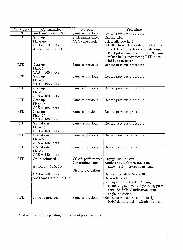
Flight deck Configuration Purpose Procedure
RFD SAC configuration 3.0 Same as previous Repeat previous procedureRFD Gear up Stick shaker check Engage RFD
Flaps up AOA vane check Select altitude holdCAS = 210 knots Set idle thrust; FFD safety pilot shouldAltitude = 10 000 ft check that throttles are on aft stop;
FFD pilot should call out CL/CLmaxvalues in 0.1 increments; RFD pilotinitiates recovery
RFD Gear up Same as previous Repeat previous procedureFlaps 1CAS -- 200 knots
RFD Gear up Same as previous Repeat previous procedureFlaps 5CAS -- 195 knots
RFD Gear up Same as previous Repeat previous procedureFlaps 10CAS -- 180 knots
RFD Gear up Same as previous Repeat previous procedureFlaps 15CAS -- 165 knots
RFD Gear up Same as previous Repeat previous procedureFlaps 25CAS -- 160 knots
RFD Gear down Same as previous Repeat previous procedureFlaps 25CAS -- 160 knots
RFD Gear down Same as previous Repeat previous procedureFlaps 30CAS = 155 knots
RFD Gear down Same as previous Repeat previous procedureFlaps 40CAS = 140 knots
RFD Cruise-trimmed VCWS performance Engage RFD VCWS
Longitudinal axis Apply 1/4 PMC step input upAltitude -- 10 000 ft allowing 2° increase in attitude
Display evaluationCAS -- 250 knots Release and allow to stabilize
SAC configuration X.lp* Return to levelDisplays verify: flight path angle
command, symbol and position, pitchattitude, VCWS indication, driftangle indication
RFD Same as previous Same as previous Repeat previous procedure for 1/4PMC down and 2° attitude decrease
*Either 1, 2, or 3 depending on results of previous runs.

June 13, 1989, TSRV Flight-Test Envelope
Flight deck Configuration Purpose ProcedureRFD Cruise-trimmed VCWS performance Engage RFD VCWS
Longitudinal axis Apply 1/4 PMC step input upAltitude = 10 000 ft allowing 2° increase in attitude
Display evaluationCAS = 250 knots Release and allow to stabilize
SAC configuration 4 Return to levelDisplays verify: flight path angle
command, symbol and position,pitch attitude, VCWS indication,drift angle indication
RFD Same as previous Same as previous Same as previouswith CAS = 300 knots
RFD Same as previous Same as previous Same as previous with 1/4 PMCwith CAS = 250 knots down and 2° attitude decrease
RFD Same as previous Same as previous Same as previous with 1/4 PMCup and 5° attitude increase
RFD Same as previous Same as previous Same as previouswith CAS -- 300 knots
RFD Same as previous Same as previous Same as previousRFD Same as previous Same as previous Same as previousRFD Same as previous Same as previous Same as previousRFD Cruise-trimmed VCWS performance :RFD engage VCWS
Longitudinal axis iIncrease flight path angleAltitude = 10000 ft in 1° steps to 5°, stabilizing
Precise control at each stepCAS = 250 knots Display symbology Return to level
checks
RFD Same as previous Same as previous Same as previous with decreasein 1° steps to -5 °, stabilizing at each
RFD Same as previous Same as previous Same as previous with increasesand using manual click trim switch
RFD Cruise-trimmed Manual electric pitch Disconnect RFDstability check Trim aircraft
Altitude > 10 000 ft Reengage RFD
SAC configuration 4 Apply 1/4 PMC step input upallowing 2 ° increase in attitude
Manual throttle fixed Release, allow to stabilizeCAS = 250 knots Return to level
Display verify: flight path anglecommand, symbol and position, pitchattitude, VCWS indication, driftangle indication
RFD Same as previous Same as previous Same as previouswith CAS -- 300 knots
10

Appendix B
Stage 2 Flight-Test Envelope
November 13_ 1989, Portion of the TSRV Flight-Test Envelope
Flight deck Configuration Purpose Procedure
RFD Altitude < 10000 ft TTFIM automatic flight-phase TXdetection check in terminal area T/O
TC, then level offTD, then level off
RFD Same as previous Same as previous TC, no level offTD, no level off
RFD Altitude > 10000 ft TTFIM automatic flight-phase TCdetection check outside terminal area EC
CR, level off, vary gamma(-1 ° and 1°)
EDCRECCR
EC, no level off, straightto next run
RFD Touch and go Same as previous for touch and go EDSTAR WFB13 TD
LD (touch and go)T/O
RFD Full mission phase Same as previous for full mission TCdetection EC
CREDTDLDTX
11

References 6. Rouse, William B.; Geddes, Norman D.; and Hammer,John M.: Computer-Aided Fighter Pilots. IEEE Spectr.,1. Steinmetz, George G.: Development and Evaluation ofvol. 27, no. 3, Mar. 1990, pp. 34-41.an Airplane Electronic Display Format Aligned With the
Inertial Velocity Vector. NASA TP-2648, 1986.7. Buchanan, Bruce G.; and Shortliffe, Edward H., eds.:
2. Abbott, Terence S.; Nataupsky, Mark; and Steinmetz, Rule-BasedExpert Systems--The MYCINExperiments ofGeorge G.: Effects of Combining Vertical and Horizontal the Stanford Heuristic Programming Project. Addison-Information Into a Primary Flight Display. NASA TP- Wesley Publ. Co., c.1984.2783, 1987.
8. Bachant, Judith; and McDermott, John: R1 Revisited--3. Ricks, Wendell R.: Knowledge-Based System for Flight Four Years in the Trenches. Readings from AI Mag.,
Information Management. NASA TM-102685, 1990. vols. 1-5, 1980-1985, pp. 177-188.
4. Ricks, Wendell R.; and Abbott, Kathy H.: TraditionalVersus Rule-Based Programming Techniques: Application 9. Barr, Avron; and Feigenbaum, Edward A., eds.: Theto the Control of Optional Flight Information. NASA TM- Handbook of Artificial Intelligence, Volume II. William89161, 1987. Kaufmann, Inc., c.1982.
5. Rushby, John: Quality Measures and Assurance for AI 10. Winston, Patrick Henry; and Horn, Berthold Klaus Paul:Software. NASA CR-4187, 1988. LISP, Third ed. Addison-Wesley Publ. Co., c.1989.
12

L-87-5527
Figure i. Primary flight display.
13

L-89-12405
Figure 2. TSRV Boeing 737 airplane.
SYSTEMSiNTERFACE
L-85-10,992Figure 3. TSRV airplane configuration.
14

L-90-8321
Figure 4. TSRV airplane experimental cockpit.
iiiii!iiiii3!iiii_iii,!ill
L-86-3593
Figure 5. TSRV simulator cockpit.
15

Pilot requests A/C sensors
Configuration commands Sensory information
ACCel_l_Bil°t's Configure automatic I Onboardand semiautomatic computersconfiguration control modes .............................................................................
I_i_i_i_i_i_i_i_i_i_i_!_i_i_i!i_i!i_i!iL_._Sensor and systemchoices
Ii!i!i!i!_ii_!!i_li_ii!iii!!!i!l- informationStatus of
display Control mode Iswitches configuration
IDetectedflight phase
__i!ii!i_i._i_!iii_ii_iiiiiiiiiiiiiil-_-j
Optionalto presentinformation
I Configure I_PFD format
PFD format with /temporal information f
I PFDGuidance and control /
information
Pilot
Data Data sinks and Process _KBS [ DataData sources _process _ stores
Figure 6. Data flow diagram of onboard system.
16


_]_A Report Documentation PageNationalAeronauticsandSpace Administration
1. Report No. 2. Government Accession No. 3. Recipient's Catalog No.
NASA TM-42794. Title and Subtitle 5. Report Date
Feasibility of Using a Knowledge-Based System Concept for September 1991
In-Flight Primary Flight Display Research 6. PerformingOrganizationCode
7. Author(s) 8. Performing Organization Report No.
Wendell R. Ricks L-16917
10. Work Unit No.9. Performing Organization Name and Address
NASA Langley Research Center 505-64-13-22Hampton, VA 23665-5225 11. Contract or Grant No.
13. Type of Report and Period Covered12. Sponsoring Agency Name and Address
National Aeronautics and Space Administration Technical Memorandum
Washington, DC 20546-0001 14. SponsoringAgencyCode
15. Supplementary Notes
16. Abstract
A study was conducted to determine the feasibility of using knowledge-based system architecturesfor in-flight research of primary flight display information-management issues. The feasibilityrelied on the ability to integrate knowledge-based systems with existing onboard aircraft systems,and the ability to use interpreted-LISP software with the real-time operation of the primaryflight display. In addition to evaluating these feasibility issues, the study described in this paperdetermined whether the software-engineering advantages of knowledge-based systems found for
this application in an earlier workstation study extended to the in-flight research environment.To investigate these issues, two integrated knowledge-based systems were designed to control theprimary flight display according to preexisting specifications of an on-going primary flight displayinformation-management research effort. These two knowledge-based systems were implementedonboard the NASA Langley Boeing-737 Transport Systems Research Vehicle aircraft to assessthe feasibility of software-engineering issues listed above. Flight test results were successful inshowing the feasibility of using knowledge-based systems in flight with actual aircraft data. And,the ease and efficiency of implementing and maintaining the systems for the flight tests confirmedthe software engineering advantages of the knowledge-based system approach for the in-flightresearch environment.
17. Key Words (Suggested by Author(s)) 18. Distribution Statement
Knowledge-based systems Unclassified--UnlimitedFlight testsFeasibilityLISP
Subject Category 03
19. SecuritYunclassifiedClassif.(of this report) 20. UnclassifiedSecurityClassif. (of this page) 21. No.17of Pages 22. A03PriceNASA FORM 1626 OCT 86 NASA-Langley, 1991
For sale by the National Technical Information Service, Springfield, Virginia 22161-2171


IIINiiiiiiiilTiiiiLiiiniilIINational Aeronautics and 3 1176 01353 7270Space Administration BULKRATECode NTT-4 POSTAGE& FEESPAID
NASAWashington, D.C. PermitNo.G-2720546-OO01
Official BusinessPenalty for Private Use. $300
If Undeltvmble (Section ! 58POSTMASTER:
Postal Manual) Do Not R_urn