feature man ual - anal yzed inf ormation features · 2012-01-08 · iar base feature message...
TRANSCRIPT

Tekelec EAGLE® 5
Feature Manual - Analyzed Information Features910-6251-001 Revision A
January 2012
Copyright 2012 Tekelec. All Rights Reserved. Printed in USA.Legal Information can be accessed from the Main Menu of the optical disc or on the
Tekelec Customer Support web site in the Legal Information folder of the Product Support tab.

Table of Contents
Chapter 1: Introduction.......................................................................7Introduction...............................................................................................................................8Scope and Audience.................................................................................................................8Manual Organization................................................................................................................8Documentation Admonishments............................................................................................9Customer Care Center..............................................................................................................9Emergency Response..............................................................................................................11Related Publications...............................................................................................................12Documentation Availability, Packaging, and Updates.....................................................12Locate Product Documentation on the Customer Support Site.......................................13
Chapter 2: Info Analyzed Relay Features......................................14Operation Overview...............................................................................................................15
MTP-Routed AnalyzedInformation Message Processing.....................................18Hardware Requirements............................................................................................19
IAR Base Feature Message Processing.................................................................................19Service Selection for AnalyzedInformation Messages...........................................20IAR Pre-NPP Processing............................................................................................21NPP Processing for IAR Features.............................................................................22IAR Base Post-NPP Processing.................................................................................27
IAR Number Portability Feature..........................................................................................27Service Portability for IAR NP..................................................................................28
IAR Additional Subscriber Data Feature ............................................................................31IAR Generic Routing Number Feature ...............................................................................32IAR-Related Feature Processing...........................................................................................32IAR-Related Features Configuration Options....................................................................33Destination-based Configuration Options for IAR Pre-NPP Processing........................34SCCP Options Configuration Option for S-Port Subscriber Differentiation..................35EAGLE 5 ISS Commands.......................................................................................................35
Chapter 3: ANSI41 AnalyzedInformation Query - noEPAP/ELAP Feature........................................................................37
Feature Description.................................................................................................................38AnalyzedInformation Message Flow.......................................................................38
ii910-6251-001 Revision A, January 2012

The AIQ Local Subsystem..........................................................................................39ANSI41 AIQ Feature Configuration Options......................................................................43EAGLE 5 ISS Commands.......................................................................................................48
Chapter 4: Feature Configuration...................................................50Introduction.............................................................................................................................51
System Prerequisites...................................................................................................51IAR-Related Features Configuration....................................................................................52
IAR-Related Feature Prerequisites...........................................................................53Configuration Procedure for IAR-Related Features..............................................53Enabling IAR-Related Features.................................................................................55Provisioning the TTR Service Selector.....................................................................56Provisioning the Common Screening List for IAR Base........................................57Provisioning the TATR Options................................................................................58Provisioning NPP for IAR-Related features............................................................59Turning On IAR-Related Features............................................................................60Enabling the MTP Routed Messages for SCCP Applications Feature................61Turning On the MTP Routed Messages for SCCP Applications Feature...........62Turning Off the MTP Routed Msgs for SCCP Apps Feature................................63TATR Test Tool............................................................................................................64
Service Portability Feature Configuration Procedures......................................................66Enabling the Service Portability Feature.................................................................66Turning On the Service Portability Feature............................................................67Turning Off the Service Portability Feature............................................................68
S-Port Subscriber Differentiation Feature Configuration Procedures.............................69Enabling the S-Port Subscriber Differentiation Feature........................................69Turning On the S-Port Subscriber Differentiation Feature...................................70Provisioning the S-Port Subscriber Differentiation SCCPOPTS Option.............71
ANSI41 AIQ Configuration...................................................................................................72ANSI41 AIQ Feature Prerequisites...........................................................................72ANSI41 AIQ Configuration Procedure....................................................................72Enabling the ANSI41 AIQ Feature...........................................................................73Provisioning the AIQ Local Subsystem...................................................................74Provisioning the AIQ Service Selector.....................................................................76Provisioning the ANSI41 AIQ Options....................................................................80Turning On the ANSI41 AIQ Feature......................................................................81Changing the State of a Subsystem Application....................................................82Activating the AIQ Local Subsystem.......................................................................82Turning Off the ANSI41 AIQ Feature......................................................................84
Adding a Service Module Card............................................................................................85
iii910-6251-001 Revision A, January 2012

The 1100 TPS/DSM for ITU NP Feature.............................................................................92Enable the 1100 TPS/DSM for ITU NP Feature......................................................95Turn On the 1100 TPS/DSM for ITU NP Feature..................................................95Turn Off the 1100 TPS/DSM for ITU NP Feature..................................................96
Activating the E5-SM4G Throughput Capacity Feature...................................................96
Chapter 5: Measurements................................................................101Measurements for IAR-Related Features...........................................................................102ANSI41 AIQ Measurements................................................................................................104
Chapter 6: Maintenance...................................................................105Alarms.....................................................................................................................................106IAR-Related UIMs.................................................................................................................106AIQ Local Subsystem Alarms.............................................................................................108AIQ Local Subsystem UIMs................................................................................................109Maintenance Commands.....................................................................................................109
rept-stat-sccp..............................................................................................................111Debug Commands................................................................................................................111Status Reporting and Problem Identification....................................................................111
EPAP Status and Alarm Reporting.........................................................................113Glossary..................................................................................................................116
iv910-6251-001 Revision A, January 2012

List of FiguresFigure 1: EAGLE 5 ISS AnalyzedInformation Message Flow......................................................38Figure 2: EAGLE 5 ISS AnalyzedInformation Message Flow Details.........................................39Figure 3: IAR Measurement Counter Pegging..............................................................................103
v910-6251-001 Revision A, January 2012

List of TablesTable 1: Admonishments.....................................................................................................................9Table 2: IAR Base Feature NPP Service Actions.............................................................................24Table 3: NPTYPE Evaluation Success...............................................................................................25Table 4: NPTYPE Success Criteria for IGM Feature and Service Portability Feature...............26Table 5: Number Portability NPTYPE RN and SP Formatting Action Population...................27Table 6: Recommended NPP Provisioning for "Routing Tags"....................................................30Table 7: TATROPTS Configuration Options...................................................................................33Table 8: Commands used for IAR-Related Features......................................................................35Table 9: Network Management Response.......................................................................................40Table 10: LIM Card Processing When Service Module Card is Unavailable.............................41Table 11: AIQOPTS Configuration Options....................................................................................43Table 12: TCAP Error Codes and Corresponding Error Strings..................................................46Table 13: Trigger Type (TRIGTYPE) Values and their Meanings................................................47Table 14: EAGLE 5 ISS Commands used for the ANSI41 AIQ Feature......................................48Table 15: System Prerequisites..........................................................................................................51Table 16: IAR-Related Feature Prerequisites...................................................................................53Table 17: TATR Test Message Table Fields.....................................................................................64Table 18: ANSI41 AIQ Feature Prerequisite....................................................................................72Table 19: AIQ Local Subsystem Prerequisites.................................................................................75Table 20: Subsystem Allow/Inhibit..................................................................................................83Table 21: Service Module Card Locations.......................................................................................85Table 22: System Prerequisites for Adding a Service Module Card............................................86Table 23: Prerequisite for Adding an E5-SM4G Service Module Card.......................................87Table 24: Prerequisites for Adding an E5-SM8G-B Service Module Card..................................87Table 25: System Prerequisites..........................................................................................................93Table 26: Feature Prerequisites..........................................................................................................94Table 27: Maximum E5-SM4G, E5-SM8G-B, and System TPS Capacity.....................................97Table 28: System Prerequisites..........................................................................................................98Table 29: E5-SM4G Throughput Capacity Feature Prerequisite..................................................99Table 30: UAM 0451..........................................................................................................................106Table 31: IAR-Related UIMs............................................................................................................106Table 32: UIM for Service Portability.............................................................................................108Table 33: AIQ Local Subsystem UAMs..........................................................................................108Table 34: AIQ Local Subsystem UIMs............................................................................................109Table 35: Maintenance Commands.................................................................................................109Table 36: Status Reporting for EPAP-Related Features...............................................................112
vi910-6251-001 Revision A, January 2012

Chapter
1Introduction
This manual describes the following features:Topics:
• Info Analyzed Relay features (IAR Base, IAR NP,IAR ASD, and IAR GRN) - Provide EAGLE 5 ISS
• Introduction.....8• Scope and Audience.....8 provisioning of subscriber data to be used to• Manual Organization.....8 screen and manipulate AnalyzedInformation• Documentation Admonishments.....9 messages related to ported subscribers differently• Customer Care Center.....9 than messages related to non-ported subscribers.
Other network entities then do not have to• Emergency Response.....11distinguish one kind of subscriber from another,• Related Publications.....12but only react to message data that is alreadyscreened and manipulated by the EAGLE 5 ISS.• Documentation Availability, Packaging, and
Updates.....12 • ANSI41 AnalyzedInformation Query - noEPAP/ELAP (ANSI41 AIQ) feature - Allows an• Locate Product Documentation on the Customer
Support Site.....13 operator to migrate customers from onetechnology to another (such as CDMA to LTE);does not require connection to or a Real TimeDatabase (RTDB) from an EPAP or ELAP.
7910-6251-001 Revision A, January 2012

Introduction
This manual describes the following features:
• Info Analyzed Relay features - (IAR Base, IAR NP, IAR ASD, IAR GRN) Provide provisioning ofsubscriber data to be used to screen and manipulate AnalyzedInformation messages related toported subscribers differently than messages related to non-ported subscribers.
• Service Portability - With IAR NP, allows an own-network subscriber to port to a differentnetwork technology with the same service provider.
• S-Port Subscriber Differentiation - Can be used with the Service Portability feature to allow useof ASD digits to provide an additional Routing Number per own-network subscriber. (ASDdigits, if provisioned, are used in place of GRN digits.)
• ANSI41 AnalyzedInformation Query - no EPAP/ELAP (ANSI41 AIQ) feature - Allows networkoperators to migrate subscribers from one technology to another (such as CDMA to LTE), usinginformation in the incoming message and information provisioned on the EAGLE 5 ISS (RTDBlookup is not required); provides the ability to indicate which calls are destined for a particulartechnology.
Scope and Audience
This manual is intended for anyone responsible for installing, maintaining, and using AnalyzedInformation features in the EAGLE 5 ISS. Users of this manual and the others in the EAGLE 5 ISSfamily of documents must have a working knowledge of telecommunications and network installations.
Manual Organization
This document is organized into the following chapters:
• Introduction contains general information about the documentation for Analyzed Informationfeatures, organization of this manual, and how to get technical assistance.
• Info Analyzed Relay Features describes the functions, user interface, and message protocols for theInfo Analyzed Relay Base feature and related features IAR Number Portability, IAR AdditionalSubscriber Data, and IAR Generic Routing Number.
• ANSI41 AnalyzedInformation Query - no EPAP/ELAP Feature describes the functions, user interface,and message protocols for the ANSI41 AIQ feature.
• Feature Configuration provides procedures for configuring the Analyzed Information features foruse in the EAGLE 5 ISS.
• Measurements describes Analyzed Information feature-related measurements, measurements reports,and methods of collection.
8910-6251-001 Revision A, January 2012
IntroductionFeature Manual - Analyzed Information Features

• Maintenance describes Analyzed Information feature-related UAMs and UIMs; commands that canbe used for maintenance functions; and status and alarm reporting for the EAGLE 5 ISS, EPAP,Service Module cards, services, and the local subsystem.
Documentation Admonishments
Admonishments are icons and text throughout this manual that alert the reader to assure personalsafety, to minimize possible service interruptions, and to warn of the potential for equipment damage.
Table 1: Admonishments
DANGER:
(This icon and text indicate the possibility of personal injury.)
WARNING:
(This icon and text indicate the possibility of equipment damage.)
CAUTION:
(This icon and text indicate the possibility of service interruption.)
Customer Care Center
The Tekelec Customer Care Center is your initial point of contact for all product support needs. Arepresentative takes your call or email, creates a Customer Service Request (CSR) and directs yourrequests to the Tekelec Technical Assistance Center (TAC). Each CSR includes an individual trackingnumber. Together with TAC Engineers, the representative will help you resolve your request.
The Customer Care Center is available 24 hours a day, 7 days a week, 365 days a year, and is linkedto TAC Engineers around the globe.
Tekelec TAC Engineers are available to provide solutions to your technical questions and issues 7days a week, 24 hours a day. After a CSR is issued, the TAC Engineer determines the classification ofthe trouble. If a critical problem exists, emergency procedures are initiated. If the problem is not critical,normal support procedures apply. A primary Technical Engineer is assigned to work on the CSR andprovide a solution to the problem. The CSR is closed when the problem is resolved.
Tekelec Technical Assistance Centers are located around the globe in the following locations:
Tekelec - Global
Email (All Regions): [email protected]
• USA and Canada
9910-6251-001 Revision A, January 2012
IntroductionFeature Manual - Analyzed Information Features

Phone:
1-888-FOR-TKLC or 1-888-367-8552 (toll-free, within continental USA and Canada)
1-919-460-2150 (outside continental USA and Canada)
TAC Regional Support Office Hours:
8:00 a.m. through 5:00 p.m. (GMT minus 5 hours), Monday through Friday, excluding holidays• Caribbean and Latin America (CALA)
Phone:
USA access code +1-800-658-5454, then 1-888-FOR-TKLC or 1-888-367-8552 (toll-free)
TAC Regional Support Office Hours (except Brazil):
10:00 a.m. through 7:00 p.m. (GMT minus 6 hours), Monday through Friday, excluding holidays
• Argentina
Phone:
0-800-555-5246 (toll-free)• Brazil
Phone:
0-800-891-4341 (toll-free)
TAC Regional Support Office Hours:
8:30 a.m. through 6:30 p.m. (GMT minus 3 hours), Monday through Friday, excluding holidays• Chile
Phone:
1230-020-555-5468• Colombia
Phone:
01-800-912-0537• Dominican Republic
Phone:
1-888-367-8552• Mexico
Phone:
001-888-367-8552• Peru
Phone:
0800-53-087• Puerto Rico
Phone:
10910-6251-001 Revision A, January 2012
IntroductionFeature Manual - Analyzed Information Features

1-888-367-8552 (1-888-FOR-TKLC)• Venezuela
Phone:
0800-176-6497
• Europe, Middle East, and Africa
Regional Office Hours:
8:30 a.m. through 5:00 p.m. (GMT), Monday through Friday, excluding holidays
• Signaling
Phone:
+44 1784 467 804 (within UK)• Software Solutions
Phone:
+33 3 89 33 54 00
• Asia
• India
Phone:
+91 124 436 8552 or +91 124 436 8553
TAC Regional Support Office Hours:
10:00 a.m. through 7:00 p.m. (GMT plus 5 1/2 hours), Monday through Saturday, excludingholidays
• Singapore
Phone:
+65 6796 2288
TAC Regional Support Office Hours:
9:00 a.m. through 6:00 p.m. (GMT plus 8 hours), Monday through Friday, excluding holidays
Emergency Response
In the event of a critical service situation, emergency response is offered by the Tekelec Customer CareCenter 24 hours a day, 7 days a week. The emergency response provides immediate coverage, automaticescalation, and other features to ensure that the critical situation is resolved as rapidly as possible.
A critical situation is defined as a problem with the installed equipment that severely affects service,traffic, or maintenance capabilities, and requires immediate corrective action. Critical situations affectservice and/or system operation resulting in one or several of these situations:
• A total system failure that results in loss of all transaction processing capability
11910-6251-001 Revision A, January 2012
IntroductionFeature Manual - Analyzed Information Features

• Significant reduction in system capacity or traffic handling capability• Loss of the system’s ability to perform automatic system reconfiguration• Inability to restart a processor or the system• Corruption of system databases that requires service affecting corrective actions• Loss of access for maintenance or recovery operations• Loss of the system ability to provide any required critical or major trouble notification
Any other problem severely affecting service, capacity/traffic, billing, and maintenance capabilitiesmay be defined as critical by prior discussion and agreement with the Tekelec Customer Care Center.
Related Publications
For information about additional publications that are related to this document, refer to the RelatedPublications document. The Related Publications document is published as a part of the ReleaseDocumentation and is also published as a separate document on the Tekelec Customer Support Site.
Documentation Availability, Packaging, and Updates
Tekelec provides documentation with each system and in accordance with contractual agreements.For General Availability (GA) releases, Tekelec publishes a complete EAGLE 5 ISS documentation set.For Limited Availability (LA) releases, Tekelec may publish a documentation subset tailored to specificfeature content or hardware requirements. Documentation Bulletins announce a new or updatedrelease.
The Tekelec EAGLE 5 ISS documentation set is released on an optical disc. This format allows for easysearches through all parts of the documentation set.
The electronic file of each manual is also available from the Tekelec Customer Support site. This siteallows for 24-hour access to the most up-to-date documentation, including the latest versions of FeatureNotices.
Printed documentation is available for GA releases on request only and with a lead time of six weeks.The printed documentation set includes pocket guides for commands and alarms. Pocket guides mayalso be ordered separately. Exceptions to printed documentation are:
• Hardware or Installation manuals are printed without the linked attachments found in the electronicversion of the manuals.
• The Release Notice is available only on the Customer Support site.
Note: Customers may print a reasonable number of each manual for their own use.
Documentation is updated when significant changes are made that affect system operation. Updatesresulting from Severity 1 and 2 Problem Reports (PRs) are made to existing manuals. Other changesare included in the documentation for the next scheduled release. Updates are made by re-issuing anelectronic file to the customer support site. Customers with printed documentation should contacttheir Sales Representative for an addendum. Occasionally, changes are communicated first with aDocumentation Bulletin to provide customers with an advanced notice of the issue until officially
12910-6251-001 Revision A, January 2012
IntroductionFeature Manual - Analyzed Information Features
released in the documentation. Documentation Bulletins are posted on the Customer Support site andcan be viewed per product and release.
Locate Product Documentation on the Customer Support Site
Access to Tekelec's Customer Support site is restricted to current Tekelec customers only. This sectiondescribes how to log into the Tekelec Customer Support site and locate a document. Viewing thedocument requires Adobe Acrobat Reader, which can be downloaded at www.adobe.com.
1. Log into the Tekelec Customer Support site.
Note: If you have not registered for this new site, click the Register Here link. Have your customernumber available. The response time for registration requests is 24 to 48 hours.
2. Click the Product Support tab.3. Use the Search field to locate a document by its part number, release number, document name, or
document type. The Search field accepts both full and partial entries.4. Click a subject folder to browse through a list of related files.5. To download a file to your location, right-click the file name and select Save Target As.
13910-6251-001 Revision A, January 2012
IntroductionFeature Manual - Analyzed Information Features
Chapter
2Info Analyzed Relay Features
This chapter describes the Info Analyzed Relayfeatures (IAR Base, IAR NP, IAR ASD, and IAR
Topics:
• Operation Overview.....15 GRN). The Info Analyzed Relay (IAR) features• IAR Base Feature Message Processing.....19 provide EAGLE 5 ISS provisioning of subscriber
data to be used to screen and manipulate• IAR Number Portability Feature.....27AnalyzedInformation messages related to ported• IAR Additional Subscriber Data Feature .....31subscribers differently than messages related to• IAR Generic Routing Number Feature .....32 non-ported subscribers. Other network entities then
• IAR-Related Feature Processing.....32 do not have to distinguish one kind of subscriber• IAR-Related Features Configuration Options....33 from another, but only react to message data that is
already screened and manipulated by the EAGLE5 ISS.
• Destination-based Configuration Options for IARPre-NPP Processing.....34
Service Portability can be used with the IAR NPfeature to allow the RTDB GRN value to be used asthe RN in the outgoing message.
• SCCP Options Configuration Option for S-PortSubscriber Differentiation.....35
• EAGLE 5 ISS Commands.....35S-Port Subscriber Differentiation can be used withService Portability in the IAR NP feature to allowuse of provisioned ASD digits in place of GRN digitsas an alternative Routing Number for own-networksubscribers.
14910-6251-001 Revision A, January 2012

Operation Overview
The following Info Analyzed Relay (IAR) features are used to process AnalyzedInformation messagesthat are sent from an MSC to an SCP or SN.
• IAR Base (Part Number 893034201)
IAR Base intercepts and identifies the AnalyzedInformation messages that require IAR featureprocessing, and performs all message processing.
The IAR Base feature must be on before any other IAR features can be used in the system.• IAR Number Portability (IAR NP) (Part Number 893026101)
IAR NP performs an RTDB lookup on the conditioned number from the message, distinguishesown network subscribers from foreign network subscribers, populates Formatting Action valuesused for outgoing message formatting, and performs Service Portability processing when theService Portability feature is on.
The IAR NP feature supports MNP and Service Portability processing, but it does not dictate howthe customer will use it. For example, the IAR NP feature can be used to identify subscribers thatbelong to the customer’s network, but it does not dictate whether or not AnalyzedInformationmessages associated with them should be modified before they are relayed. Each customer candecide how to represent subscribers of own and foreign networks in the RTDB. The IAR featuresallow each customer to decide how to react to that data appropriately.
Service Portability (S-Port) (Part Number 893034301) processing can be applied by the IAR NPfeature, allowing the RTDB GRN value to be used as the RN in the outgoing message.
S-Port Subscriber Differentiation (Part Number 893037901) can be used with Service Portability toallow use of provisioned ASD digits in place of GRN digits as an alternative Routing Number forown-network subscribers.
• IAR Additional Subscriber Data (IAR ASD) (Part Number 893035001)
IAR ASD provides the ability to obtain Additional Subscriber Data from the RTDB and populatethe ASD Formatting Action value with the ASD.
• IAR Generic Routing Number (IAR GRN) (Part Number 893035101)
IAR GRN provides the ability to obtain the Generic Routing Number from the RTDB and populatethe GRN Formatting Action value with the GRN.
Note: There are several features that can use GRN data: IDP A-party Blacklist, INP/G-Port /ATINPSupport for ROP, and Service Portability. The IDP A-party Blacklist feature is mutually exclusive withService Portability; the two features cannot be enabled in the same system. There is no other restrictionplaced in the code to make other combinations of features using GRN mutually exclusive with eachother. It is anticipated that the other combinations will not occur in the same system, based on marketrequirements. The combinations of features that use GRN should be considered in configuring eachsystem.
Subscriber data population and feature configuration provide information to identify subscribers asown-network or foreign network, and to determine which AnalyzedInformation messages will beprocessed by IAR features.
15910-6251-001 Revision A, January 2012
Info Analyzed Relay FeaturesFeature Manual - Analyzed Information Features

Message processing is also guided by configuration of the Numbering Plan Processor (NPP). After amessage is determined to require IAR feature processing, the NPP configuration determines whetheror not the CdPN parameter or CgPN parameter, or both, will be modified.
IAR General Relay Call Flow
The following general call flow relays AnalyzedInformation messages:
1. An incoming MSC event trips an Intelligent Network trigger.2. The MSC sends an AnalyzedInformation message to the EAGLE 5 ISS.3. The IAR Base feature intercepts an AnalyzedInformation query based on customer configured
criteria.4. The following actions are performed, based on configuration options:
• The B-Party number and A-Party number are extracted from the CdPN parameter and CgPNparameter.
• An RTDB lookup is performed on the CdPN or CgPN or both to check subscriber status.• The CdPN parameter or CgPN parameter, or both, could be modified based on configuration
options and RTDB lookup results.• The message is relayed to its original destination.
The SCP uses the information in the AnalyzedInformation message to apply a billing tariff tothe associated call, and check the balance of a prepaid subscriber, among other things. AnAnalyzedInformation response message will be returned to the originator of theAnalyzedInformation message.
The MSC handles the call based on the information in the AnalyzedInformation response. TheMSC could have been instructed to terminate the call. The SCP can also have the MSC reroutethe call by providing a DGTSDIAL parameter in the response message
Call Flow Example for a Foreign Network Subscriber
For a configuration that would modify AnalyzedInformation messages when the CdPN parameterdescribes a subscriber that is served by a foreign network, the RTDB could be provisioned to associatean RN that identifies the network supporting all foreign subscribers:
• Subscriber range records could be used for blocks of numbers that are used by foreign networks.• Individual records could be used to describe subscribers that have had their numbers ported out
of the customer's network to some foreign network.
The IAR NP feature can key off of the existence of an RTDB record for some CdPN to determine whichmessages should be modified before relay, and also use the RN in the modification. The RN wouldprobably be prepended to the original CdPN, but NPP allows the the data to be used in whatever waybest suits the needs.
The Home SCP can easily strip an RN from the front of a CdPN parameter if all of the RN values usedto provision of the RTDB are the same length.
This example represents the following processing:
1. A prepaid subscriber attempts to make a call that trips an IN trigger at the MSC. The MSC sendsan AnalyzedInformation message to the network served by the EAGLE 5 ISS.
2. The IAR Base feature intercepts the AnalyzedInformation message,and determines that it requiresIAR processing.
16910-6251-001 Revision A, January 2012
Info Analyzed Relay FeaturesFeature Manual - Analyzed Information Features

3. The IAR NP feature performs an RTDB lookup using the digit string in the CdPN parameter, andfinds that the number is associated with an RN; the B-party subscriber was ported to a foreignnetwork.
4. The IAR Base feature formats a new CdPN parameter using the RN and DN (as directed by NPP).5. The modified AnalyzedInformation message is sent to the Home SCP.6. The Home SCP detects and strips the RN from the CdPN parameter, and uses it to determine an
appropriate tariff rate for the call.
Call Flow Example for an Own Network Subscriber
The following processing illustrates a call to an own-network subscriber:
1. A prepaid subscriber attempts to make a call that trips an IN trigger at the MSC. The MSC sendsan AnalyzedInformation message to the network served by the EAGLE 5 ISS.
2. The IAR Base feature intercepts the AnalyzedInformation message,and determines that it requiresIAR processing.
3. The IAR NP feature performs an RTDB lookup using the digit string in the CdPN parameter, andfinds that the number is not associated with an RN; the B-party subscriber was ported into thecustomer's network.
4. The IAR Base feature does not modify the CdPN parameter.5. The unmodified AnalyzedInformation message is sent to the Home SCP.6. The Home SCP detects the lack of an RN in the CdPN parameter, and associates an appropriate
tariff rate with the call.
NPP
Message processing is also guided by configuration of the Numbering Plan Processor (NPP). After amessage is determined to require IAR feature processing, the NPP configuration determines whetheror not the CdPN parameter will be modified.
NPP processing relies on Nature of Address Indicator (NAI) values. These values are available inSCCP parameters and GSM MAP parameters, but they are not available in the CdPN and CgPNparameters of AnalyzedInformation query operations. The National Indicator bit (least significant bit)of the Nature of Number field in the CdPN and CgPN will be used wherever the NAI is called for inthis document.
Interaction with Other EAGLE 5 ISS Functions
MTP-Routed Messages
All incoming GT-routed traffic is sent to a Service Module card by the LIM card that receives it, butMTP-routed traffic may not be. See MTP-Routed AnalyzedInformation Message Processing.
• The Gateway Screening (GWS) feature on a LIM card inspects message traffic before it is directedto a Service Module card. GWS can be used to select incoming MTP-routed traffic for ServiceModule card processing on a linkset basis.
• The MTP Routed Messages for SCCP Applications feature can be used to direct all MTP routedSCCP messages to Service Module cards for service selection processing.
IS41 GSM Migration
When the IGM feature is ON; an IS41 own-network subscriber will be associated with an RN entityand a Portability Type of 0, instead of an SP entity.
17910-6251-001 Revision A, January 2012
Info Analyzed Relay FeaturesFeature Manual - Analyzed Information Features

MTP-Routed AnalyzedInformation Message Processing
An MTP-routed message is a “through-switched” message that is not generated by or destined to theEAGLE 5 ISS (neither the MTP OPC nor DPC is the EAGLE 5 ISS true point code or capability pointcode). An MTP-routed message is routed to the destination designated by the DPC of the MTP3 routinglabel.
Typically, MSUs that receive service on a Service Module card require the message to be GT-routedto the EAGLE 5 ISS, so that GTT service selector-based discrimination can be applied to the messageto select a specific service (such as TTR or IDPR). Some MTP-routed messages might not contain GlobalTitle digits (GTI=0); they are referred to as "GTI=0" messages. The GTT Service Selector cannot beapplied.
The IAR Base feature can process MTP-routed SCCP messages with SCCP CdPA GTI=0 and an ANSITCAP Query With Permission package that has a Invoke Last component that contains an ANLYZDoperation. One of the following methods can be used:
• The MTP Routed Messages for SCCP Applications (MTP Msgs for SCCP Apps) feature
The feature is available system-wide and sends all MTP-routed SCCP messages from LIM cardsto Service Module cards for processing.
The feature can be enabled and turned on when the GTT feature is turned on.• The MTP Routed GWS Stop Action feature with Gateway Screening
The MTP Routed GWS Stop Action feature (Part Number 893-0356-01; also called MTPRTD GWSStop Action) can be turned on and off after it has been enabled.
The Gateway Screening SCCP Stop Action can be provisioned only if the MTP Routed GWS StopAction feature is enabled, and must be the last stop action in the GWS action set.
The SCCP Stop Action is mutually exclusive with the TIF, TIF2, TIF3, TLNP, CNCF and RDCTStop Actions. Screening with the SCCP Stop Action occurs only when the MTP Routed GWS StopAction feature is turned on.
When the MTP Routed GWS Stop Action feature is on, and Gateway Screening (GWS) is provisionedto screen MSUs using the GWS SCCP Stop Action, only UDT, UDTS, XUDT, and XUDTS SCCPmessages are sent from a LIM card to a Service Module card for processing.
Gateway Screening is applied to messages on a linkset basis, and it is applied to all traffic on thatlinkset. The GWS SCCP Stop Action must be configured to process MTP-routed traffic on appropriatelinksets.
In case of failure, the screened MSU continues with MTP routing. (Failure is the LIM card couldnot deliver MSU to SCCP Service Module due to some reason, such as all Service Module cardsare out of service or Service Module cards deny service grant.)
Both the MTP Routed GWS Stop Action and MTP Msgs for SCCP Apps features can be turned on atthe same time.
When both features are turned on, the MTP Msgs for SCCP Apps feature takes precedence over theMTP Routed GWS Stop Action feature. The MTP Msgs for SCCP Apps feature forwards the SCCPmessage to a Service Module card whether or not the message is screened by the GWS SCCP StopAction.
When a Service Module card receives an MTP-routed AnalyzedInformation message that has GTI=0in the Address Indicator, the IAR Base feature is selected to process the message.
18910-6251-001 Revision A, January 2012
Info Analyzed Relay FeaturesFeature Manual - Analyzed Information Features
The IAR Base feature processes only those GTI Zero messages that are bound for a Home SCP.
The IAR Base feature performs DPC Screening on the message.
• The message DPC is compared with DPCs with the HOMESCP option provisioned in the Destinationtable.
• If a matching DPC that is a full point code for a Home SCP is found, then the IAR Base feature willcontinue processing the message.
• Otherwise, the message is dismissed.
The IAR Base feature processing for GTI=0 messages that pass the DPC screening is the same as theprocessing other AnalyzedInformation messages, as described in IAR Pre-NPP Processing, NPP Processingfor IAR Features, and IAR Base Post-NPP Processing.
After the MTP-routed SCCP message is processed by a Service Module card, the MSU is MTP routedif the processing indicates to do so. If the message was dismissed due to errors in processing, themessage is relayed without modification.
While routing the MTP-routed SCCP message to its destination, if the DPC is not defined in the Routetable, then UIM 1004 is generated along with a TFP to the adjacent node. The message is discarded.
Hardware Requirements
EPAP-related features that perform an RTDB lookup require Service Module cards (DSM cards,E5-SM4G cards, or E5-SM8G-B cards) running the VSCCP application. The EAGLE 5 ISS can beequipped with up to 32 (31+1) Service Module cards.
Features that do not perform an RTDB lookup require Service Module cards only for GTT processingthat might be performed for the feature. These features can coexist in systems with EPAP, but do notrequire an EPAP connection.
IAR Base Feature Message Processing
The IAR Base feature provides the message processing functions upon which the other IAR-relatedfeatures are built. The other IAR-related features modify how AnalyzedInformation messages arehandled as they pass through the IAR Base feature. The IAR Base feature performs allAnalyzedInformation message processing.
The IAR Base feature processes AnalyzedInformation messages that are sent from an MSC to an SCPor SN.
• Called Party Number (CdPN) parameters are used to carry B-Party numbers in MAP messages.WIN AnalyzedInformation operations have one or two CdPNs: the DSTDGTS parameter, theDGTSDIAL parameter, or both. ANSI AnalyzedInformation messages use only the DGTSDIALparameter.
• Calling Party Number (CgPN) parameters are used to carry A-Party numbers in MAP messages.Both WIN and ANSI AnalyzedInformation messages use the CPNDGTS1 parameter to carry theCgPN.
• The IAR Base feature only uses A-Party and B-Party numbers that are encoded using the BinaryCoded Decimal (BCD) format.
19910-6251-001 Revision A, January 2012
Info Analyzed Relay FeaturesFeature Manual - Analyzed Information Features

A message that reaches the Service Module card when the IAR Base feature is enabled and turned onis subjected to further analysis to determine if it needs processing by the IAR Base feature.
IAR Base feature message processing has four main components:
• Service Selector processing• IAR pre-NPP processing• NPP processing for IAR• IAR post-NPP processing
IAR Base message processing has the following considerations:
• All messages that are received by the TTR Service Selector on the Service Module card are eventuallyrouted, whether or not they are modified first.
• A message that is routed to the IAR Base feature from the TTR Service Selector may not pass IARpre-NPP processing.
• A message that passes through NPP processing still may not have any IAR-specific modificationmade to it.
Service Selection for AnalyzedInformation Messages
On a Service Module card, the service selection process selects messages for IAR processing in thefollowing sequence of steps:
1. Check for SCCP CdPA GTI=0.
If GTI is not 0, service selection continues as described in Step 2.
If GTI=0, verify that the IAR Base feature is on.
If the IAR Base feature is not on, the message is dismissed.
If the IAR Base feature is on, the message is sent to the IAR Base feature for Pre-NPP processingSee IAR Pre-NPP Processing.
Additional service selection is bypassed, because GTI=0 messages do not contain the GT informationin the CdPA parameter that is required for the additional service selection.
2. Decode the SCCP layer to identify the CdPA and CgPA parameters.
Decoding errors cause the message to be dismissed.3. Compare provisioned Service Selector data to the CdPA SCCP data (Global Title Indicator, - GTI
Subsystem Number, SSN Translation Type - TT, Nature of Address Indicator - NAI, and NumberingPlan - NP) to determine whether the TTR service applies to the message.
The message will be handled by another service or dismissed if the TTR service is not selected.
If the TTR service is selected, processing continues with Step 4.4. The TTR service verifies that the TCAP layer of the message starts with a PRIVATE tag (the ANSI
TCAP Package Type is defined using PRIVATE tag values).
If the PRIVATE tag is present, the TTR service verifies that the IAR Base feature is on.
If the IAR Base feature is on, the IAR Base feature begins IAR Pre-NPP processing on the message.See IAR Pre-NPP Processing.
If the IAR Base feature is not on, the message is dismissed.
20910-6251-001 Revision A, January 2012
Info Analyzed Relay FeaturesFeature Manual - Analyzed Information Features

IAR Pre-NPP Processing
The IAR Base feature applies IAR pre-NPP processing to SCCP UDT message and unsegmented XUDTmessages; all other SCCP messages are dismissed.
The IAR Base feature applies pre-NPP screening to a message in the following sequence:
Note: NPP processing relies on Nature of Address Indicator (NAI) values. These values are availablein SCCP parameters and GSM MAP parameters, but they are not available in the CdPN and CgPNparameters of AnalyzedInformation query operations. The National Indicator bit (least significant bit)of the Nature of Number field in the CdPN and CgPN will be used wherever the NAI is called for inthis document.
DPC Screening or SCCP CdPA GT Digit Screening
• DPC Screening
The IAR Base feature applies DPC Screening to MTP-routed messages with SCCP CdPA GTI=0.
• DPC screening compares the message DPC with DPCs provisioned with the HOMESCP optionin the Destination table.
• If a matching DPC that is a full point code for a Home SCP is found, the IAR Base featureprocessing continues for the message.
• If no Home SCP DPC match is found, the message is dismissed.
• SCCP CdPA GT Digit Screening
The IAR Base feature applies CdPA GT Digit Screening to GT-routed and MTP-routed messageswith SCCP CdPA GTI not 0.
CdPA GT Digit Screening can be used to make sure that the IAR Base feature processes onlymessages that are bound for a customer Home SCP.
• The IAR Base feature compares the CdPA parameter GT digits to a list of digits string valuesprovisioned in the GT list of the Common Screening List (CSL) table.
• The IAR Base feature continues processing the message only if a match is found.• If a match is not found, the message is dismissed.
TCAP and MAP Decoding
The IAR Base feature decodes the TCAP portion of the message to continue processing. The IAR Basefeature checks the structure of the message, checks to make sure that the message carries anAnalyzedInformation operation, and identifies the MAP CdPN and CgPN parameters.
• The message must contain an ANSI TCAP Query with Permission package; if not, the message isdismissed.
• The IAR Base feature uses and modifies only data within the first Invoke Last TCAP componentportion of the message.
• The IAR Base feature handles WIN Standard Phase 2 ANLYZD operations.• The MAP layer can contain a DSTDGTS parameter, a DGTSDIAL parameter, or both.
• If only a DSTDGTS parameter is present, or both parameters are present, the DSTDGTS parameteris used as the CdPN.
• If only a DGTSDIAL parameter is present, the DGTSDIAL parameter is used as the CdPN.• If neither parameter is present, UM 1427 is generated and the message is dismissed.
21910-6251-001 Revision A, January 2012
Info Analyzed Relay FeaturesFeature Manual - Analyzed Information Features

• The MAP layer CPNDGTS1 parameter is used as the CgPN.
• If the CPNDGTS1 parameter is not present, UIM 1428 is generated and the message is dismissed.• Messages that contain TCAP decoding errors relating to the CgPN parameter will be dismissed
and the associated UIM will be issued, only if and when CgPN processing is to be used - if theIARCDPN service invokes the IARCGPN service.
• If the CdPN or CgPN parameter is not encoded in BCD format, UIM 1427 or UIM 1428 is generatedand the message is dismissed.
• If the MAP layer does not contain a TRIGTYPE parameter, UIM 1429 is generated and the messageis dismissed.
Trigger Type Screening
The message TRIGTYPE parameter indicates the kind of trigger that caused the AnalyzedInformationmessage to be sent:
• The Calling_Routing_Address_Available trigger that trips when an MSC has all of the informationit needs to route a call
• The Initial_Termination and Called_Routing_Address_Available triggers that trip when an MSCis handling a call to a prepaid subscriber
The IAR Base feature compares the message TRIGTYPE parameter value to numeric values provisionedin the TRIGTYPE list of the CSL table.
The IAR Base feature continues processing only if an exact match is found.
If an exact match is not found, the message is dismissed.
SCCP CgPA Default Country Code (DEFCC) Check
This check can be used when a roaming subscriber dials a number that is local to the area in which heis roaming, and uses the national number format instead of international format. MNP control doesnot need to be applied across international boundaries. The IAR Base feature will not process messagessent on behalf of a roaming subscriber calling a number in national format.
CgPA DEFCC screening is enabled and disabled by the CGPACCCK configuration option, independentof provisioning of the STPOPTS DEFCC option.
• The check is not performed if the CGPACCCK option value is NONINTL and the CdPN NationalIndicator bit of the Nature of Number field is INTL.
• The check is not performed if the SCCP CgPA does not contain GT digits (GTI=0), or if the SCCPCgPA contains and NAI (GTI=4) and the SCCP CgPA NAI is not International.
If the CGPACCCK option is on, the IAR Base feature compares the SCCP CgPA parameter value to aprovisioned Default Country Code (STPOPTS DEFCC parameter value).
• The IAR Base feature will continue processing only if the SCCP CgPA matches the Default CountryCode.
• If no match is found, the message is dismissed.
NPP Processing for IAR Features
If a message passes all IAR pre-processing, then NPP processing is applied to it.
Refer to the Numbering Plan Processor (NPP) Overview manual for descriptions of NPP componentsand procedures for NPP provisioning.
22910-6251-001 Revision A, January 2012
Info Analyzed Relay FeaturesFeature Manual - Analyzed Information Features

Note: NPP processing relies on Nature of Address Indicator (NAI) values. These values are availablein SCCP parameters and GSM MAP parameters, but they are not available in the CdPN and CgPNparameters of AnalyzedInformation query operations. The National Indicator bit (least significant bit)of the Nature of Number field in the CdPN and CgPN will be used wherever the NAI is called for inthis document.
The IAR Base feature defines two NPP services:
• IARCDPN - The service that processes Called Party (CdPN; B-Party) Numbers
The IAR Base feature invokes IARCDPN for every message that passes IAR pre-NPP processing.
The value of the National Indicator bit of the Nature of Number field of the CdPN is passed as theNAI to NPP when the IARCDPN service is applied to the message.
The IARCDPN service always executes before the IARCGPN service. The IARCDPN service Rulemust be provisioned with the CgPNSVCRqd, CgPNASDRqd, or CgPNGRNRqd Service Action toinvoke the IARCGPN service.
• IARCGPN - The service that processes Calling Party Number (CgPN), A-Party) Numbers.
The IARCGPN service is invoked only by the IARCDPN service when the CgPNSVCRqd,CgPNASDRqd, or CgPNGRNRqd Service Action is provisioned in the NPP Rule.
The value of the National Indicator bit of the Nature of Number field of the CgPN is passed as theNAI to NPP when the IARCGPN service is applied to the message.
IAR Base NPP processing consists of the following functions:
• Verify that the IARCDPN service status is ON.• Execute IARCPDN processing.
• Apply NPP filters to select the appropriate NPP Rule for the message processing.• Execute provisioned Conditioning Actions and Service Actions.
• The Conditioning Actions can condition the CdPN digit string RTDB lookup, and can extractdata to populate the values for the provisioned Formatting Actions.
• The CDPNNP Service Action can be executed to apply number portability processing if theIAR NP feature is on, apply Service Portability processing if the Service Portability featureis on, and populate provisioned Formatting Action values.
• If the CgPNSVCRqd, CgPNASDRqd, or CgPNGRNRqd Service Action is provisioned in theNPP Rule, call the IARCGPN service.
• Execute IARCGDN processing.
• Apply NPP filters to select the appropriate NPP Rule for the message processing.• Execute provisioned Conditioning Actions and Service Actions.
• The Conditioning Actions can condition the CgPN digit string for RTDB lookup, andcan extract data to populate the values for the provisioned Formatting Actions.
• The CGPNNP Service Action can be executed to apply number portability processingif the IAR NP feature is on, and populate provisioned Formatting Action values.
• Execute Formatting Actions for modifying the CgPN in the outgoing digit string if requiredby provisioning and processing results.
23910-6251-001 Revision A, January 2012
Info Analyzed Relay FeaturesFeature Manual - Analyzed Information Features

• Execute Formatting Actions for modifying the CdPN in the outgoing digit string, if required byprovisioning and processing results.
Conditioning Actions
The IARCDPN and IARCGPN services can use all general NPP Conditioning Actions.
Service Actions
For each service, the NPP service status must be ON for service processing to occur.
The IAR Base feature NPP services use the Service Actions shown in Table 2: IAR Base Feature NPPService Actions.
Table 2: IAR Base Feature NPP Service Actions
IARCGPNIARCDPNPrecedenceFeatureService Action
YesYes50IAR ASDASDLKUP
NoYes100IAR BaseCCNCCHK
YesYes10IAR BaseCDIAL
NoYes80IAR NPCDPNNP
NoYes50IAR ASDCgPNASDRqd
NoYes50IAR GRNCgPNGRNRqd
YesNo80IAR NPCGPNNP
NoYes60IAR BaseCgPNSVCRqd
YesYes50IAR GRNGRNLKUP
Provisioning restrictions require specific features to be enabled when defining NPP Rules. The statusof each of the ON/OFF features is also checked at run-time. The ASDLKUP and CGPNASDRQDcannot be provisioned in the same Rule. The GRNLKUP and CGPNGRNRQD Service Actions cannotbe provisioned in the same Rule.
In the following Service Action summaries, the term DN is used to describe a value that is the resultof applying Conditioning Action execution to the digit string passed into an NPP service. The DNwithin the IARCDPN service is the CdPN in international format. The DN within the IARCGPN serviceis the CgPN in international format.
• ASDLKUP - Populates the ASD Formatting Action value using the ASD found in the RTDB lookup.• CCNCCHK - Highest precedence Service Action for IAR. Compares the first digits of the DN to
the entries in the CCNC list of the CSL table. If a match is found, NPP processing continues. If amatch is not found, all other Service Actions in the NPP Rule are ignored,, the message is notmodified, and the message is dismissed.
• CDiAL - Requests Formatting Action execution to be performed even when the prior Service Actionrequested that it be skipped.
• CDPNNP - Applies CdPN number portability functions for IARCDPN when the IAR NP featureis on; applies Service Portability and S-Port Differentiation functions when the features and optionsare on; evaluates the result of an RTDB lookup based on the TATROPTS CDNPTYPE option value,or on the SPORTTYPE option value for Service Portability. Populates the RN or SP FormattingAction value with the data from the RTDB lookup or the provisioned DFLTRN option value,
24910-6251-001 Revision A, January 2012
Info Analyzed Relay FeaturesFeature Manual - Analyzed Information Features

depending on provisioning and lookup results. Populates the SRFIMSI Formatting Action valuewith the SRFIMSI associated with the RN or SP entity from the RTDB, if any.
• CGPNASDRQD - Used by the IARCDPN service to invoke the IARCGPN service, and to populatethe ASD Formatting Action value prior to IARCDPN Formatting Action execution.
• CGPNGRNRQD - Used by the IARCDPN service to invoke the IARCGPN service, and to populatethe GRN Formatting Action value prior to IARCDPN Formatting Action execution.
• CGPNNP - Applies CgPN number portability functions when the IAR NP feature is on and theIARCGPN service is invoked; evaluates the result of an RTDB lookup based on the TATROPTSCGNPTYPE option value. Populates the SRFIMSI Formatting Action value with the SRFIMSIassociated with the RN or SP entity from the RTDB, if any.
• CDPNSVCRQD - Used by the IARCDPN service to invoke the IARCGPN service for CgPNprocessing.
• GRNLKUP - Populates the GRN Formatting Action value using the GRN found in the RTDB lookup.
Formatting Actions
Both services can use all general NPP Formatting Actions.
Formatting Action execution can modify the CdPN or CgPN, or both, in the outgoing digit stringbefore IAR NPP post-processing begins.
NPP RTDB Lookup and NPTYPE EvaluationRTDB lookup is performed at the request of the CDPNNP and CGPNNP Service Action Handlers thatare used by the IARCDPN and IARCGPN services.
RTDB lookup is performed once per service execution.
A conditioned number of maximum 15 digits is used to query RTDB records for individual subscribers.If a matching record is found then processing continues based on that record. Otherwise, the numberis used to query RTDB records for subscriber groups. If a match is found, processing continues basedon that record.
The NPTYPE Evaluation process uses the result of the RTDB Lookup process, and is guided by eitherthe TATROPTS:CDNPTYPE or TATROPTS:CGNPTYPE option value. The option value is used todetermine whether the lookup result was a success or a failure. For example, if the option is set to SPthen the lookup result is a success only if a matching record was found and that record contains anSP entity.
• For the IARCDPN service, the CdPN from the message is conditioned, and the lookup success isdetermined by the TATROPTS CDNPTYPE option value.
• For the IARCGPN service, the CgPN from the message is conditioned, and the lookup success isdetermined by the TATROPTS CGNPTYPE option value.
Table 3: NPTYPE Evaluation Success
Success CriteriaConfiguration Option Value
An RTDB match is found with an RN entity and PT is not 0.RN
An RTDB match is found with an RN entity and PT = 0, if theService Portability feature is not enabled or the IGM feature is OFF.
An RTDB match is found with an SP entity.SP
25910-6251-001 Revision A, January 2012
Info Analyzed Relay FeaturesFeature Manual - Analyzed Information Features

Success CriteriaConfiguration Option Value
An RTDB match is found with an RN entity and PT = 0 if theService Portability feature is enabled or the IGM feature is ON.
An RTDB match is found with an RN or SP entity.RNSP
An RTDB match is found with an RN or SP entity.RNSPDN
Always matchesALWAYS
An RTDB matching record exists.ANYMATCH
IS41 GSM Migration (IGM) Feature
IGM functions are applied by the CDPNNP and CGPNNP Service Actions. When the IGM feature isON, the IAR NP feature interprets RTDB subscriber data slightly differently: A customer’s own IS41subscribers are associated with RN entities that have a Portability Type of 0. This affects the NPTYPEEvaluation procedure.
Table 4: NPTYPE Success Criteria for IGM Feature and Service Portability Feature
SuccessNPTYPEOption
When an RTDB match is found with an RN entity that has a Portability Type otherthan 0
RN
When an RTDB match is found with an SP entity, or an RN entity that has aPortability Type of 0
SP
When an RTDB match is found with an RN or SP entityRNSP
RNSPDN
AlwaysALWAYS
When an RTDB match is foundANYMATCH
This data interpretation also applies for the purposes of RN and SP Formatting Action population;when the IGM feature is ON, and the IAR NP feature is handling an IS41 subscriber associated withan RN entity with Portability Type of 0, the RN entity is treated as if it were an SP entity in Table 5:Number Portability NPTYPE RN and SP Formatting Action Population.
IAR NPP Number PortabilityThe IAR Number Portability feature (IAR NP) can be called by the IAR Base feature to apply NumberPortability functions using both the CDPNNP and CGPNNP NPP Service Actions. See IAR NumberPortability Feature.
When the Service Portability feature is on with the IAR NP feature, the the CDPNNP and CGPNNPNPP Service Actions can also apply service portability functions. See Service Portability for IAR NP.
The S-Port Subscriber Differentiation feature can work with the Service Portability feature to allowuse of ASD digits to provide an additional routing number per in-network subscriber (in addition to
26910-6251-001 Revision A, January 2012
Info Analyzed Relay FeaturesFeature Manual - Analyzed Information Features

the GRN routing number per in-network subscriber). Subscribers without ASD provisioned will followstandard S-Port processing and will always use GRN. See S-Port Subscriber Differentiation.
NPP Formatting Action value population occurs when the RTDB lookup success criteria are met (seeNPP RTDB Lookup and NPTYPE Evaluation). If the success criteria are not met, then the CDPNNP andCGPNNP Service Action Handlers will request that Formatting Action execution be skipped for therespective service only.
Note: The TATROPTS:DFLTRN option value overrides an SP entity when one is provisioned in theRTDB.
When the RTDB does not contain an RN or SP entity, but the NPTYPE Evaluation success criteria arestill met (ALWAYS or ANYMATCH), then neither the RN Formatting Action value nor the SPFormatting Action value is changed.
Table 5: Number Portability NPTYPE RN and SP Formatting Action Population
SP Entity No DFLTRNSP Entity and DFLTRNRTDB has RN EntityNPTYPE Option
(failure)(failure)Set RN FormattingAction value to RTDB
RN
RN. SP FormattingAction value notchanged.
RN Formatting Actionvalue not changed, SP
Set RN FormattingAction value to
(failure)SP
Set RN FormattingAction value to RTDB
RNSP Formatting Action valueset to RTDB SP.
DFLTRN. SP FormattingAction value notchanged.
RNSPDN RN. SP FormattingAction value notchanged.
ALWAYS
ANYMATCH
IAR Base Post-NPP Processing
The IAR Base feature pulls together the results of the IARCDPN and IARCGPN service processing todetermine whether or not the message should be modified.
If required, the message is encoded with any modified parameters.
The IARPASSD and IARFAILD measurement pegs are updated.
The message is routed.
IAR Number Portability Feature
The Number Portability (IAR NP) feature, the Numbering Plan Processor (NPP), the Service Portabilityfeature, and the S-Port Subscriber Differentiation feature support Mobile Number Portability (MNP),Service Portability (S-Port), and S-Port Subscriber Differentiation functions.
IAR NP uses provisioning of subscriber data to treat messages that relate to ported subscribersdifferently than it does non-ported subscribers. In this way, other entities in the customer network
27910-6251-001 Revision A, January 2012
Info Analyzed Relay FeaturesFeature Manual - Analyzed Information Features

can treat these subscribers differently by simply reacting to the message data screened and manipulatedby the EAGLE 5 ISS, rather than having to distinguish one kind of subscriber from another themselves.
Feature and NPP configuration options can be used to identify which AnalyzedInformation messagesneed processing by IAR-related features.
After the IAR Base feature determines that an AnalyzedInformation message requires IAR processing,IAR NP can perform an RTDB lookup using the digit string in the CdPN parameter or the CgPNparameter, or both. RTDB subscriber data from the the lookup results can be used to identify whichsubscribers belong to a customer's own network and which belong to a foreign network.
Depending on the RTDB lookup results, IAR NP can modify RN and DN of the CdPN parameter orthe CgPN parameter, or both, in the message. If the Service Portability feature is used with IAR NPand GRN data is found in the RTDB lookup, the IAR NP feature can use the GRN data to modify theCdPN RN.
When IAR NP and NPP processing is complete for the message, the IAR Base feature relays the messageto the originator.
Service Portability for IAR NP
With the Service Portability feature (Part Number 893034301), the subscriber can port to a differentnetwork technology with the same service provider. Service Portability is applied only to the subscribersserved by the customer's own network.
• The subscriber is considered as an own-network IS41 subscriber if the Entity type is RN and thePortability Type is 0 (RN/PT=0). In the case of RN/PT=0, the RN for this subscriber is consideredto be the SP (the IS-41 HLR address).
• The subscriber is considered as an own-network GSM subscriber if the Entity type is SP with anyPortability Type.
Service Portability is handled by the NPP CDPNNP Service Action Handler in the IAR NP feature.The SPORTTYPE option in the TATROPTS table controls the mode of Service Portability that is appliedfor IAR NP. The SPORTTYPE option has the following values:
• NONE - Apply standard NP processing for own-network GSM and IS41 subscribers.• GSM - Use the GSM Service Portability prefix (GRN) for GSM own-network subscribers, and apply
standard NP processing for own-network IS41 and OLO subscribers.• IS41 - Use the IS41 Service Portability prefix (GRN) for Is41 own-network subscribers, and apply
standard NP processing for own-network GSM and OLO subscribers.• ALL - Use the GSM Service Portability prefix (GRN) for GSM own-network subscribers, use the
IS41 Service Portability prefix (GRN) for IS41 own-network subscribers, and apply standard NPprocessing for OLO subscribers.
The NPTYPE Evaluation criteria for the Service Portability feature are the same as those for the IGMfeature. See Table 4: NPTYPE Success Criteria for IGM Feature and Service Portability Feature.
After the Service Portability feature is considered to be applicable, the CDPNNP Service Action usesthe subscriber GRN data in the RTDB to populate the the Service Portability prefix in the RN FormattingAction value.
If the GRN is not present in the RTDB, then UIM 1426, “S-Port: Missing GRN for srvc prtd subs” isgenerated indicating that Service Portability could not be applied due to missing Service Portabilitydata.
28910-6251-001 Revision A, January 2012
Info Analyzed Relay FeaturesFeature Manual - Analyzed Information Features

S-Port Subscriber DifferentiationS-Port Subscriber Differentiation can be used with Service Portability to allow use of provisioned ASDdigits in place of GRN digits as an alternative Routing Number for own-network subscribers. Forexample, the ASD can be used as the subscriber’s private routing number (for message relay features)and the GRN as the subscriber’s public routing number (for query/response features).
The S-Port Subscriber Differentiation controlled feature (Part Number P/N 893-0379-01) and theSCCPOPTS SUBDFRN configuration option control S-Port Subscriber Differentiation operation. TheSUBDFRN option cannot be provisioned unless the S-Port Subscriber Differentiation feature is enabledand turned on.
When the Service Portability feature and option are on, the S-Port Subscriber Differentiation featureand option are on, and Service Portability is applicable, then provisioned ASD digits are used in placeof GRN digits.Subscribers without ASD provisioned will follow standard Service Portability processingand will always use GRN.
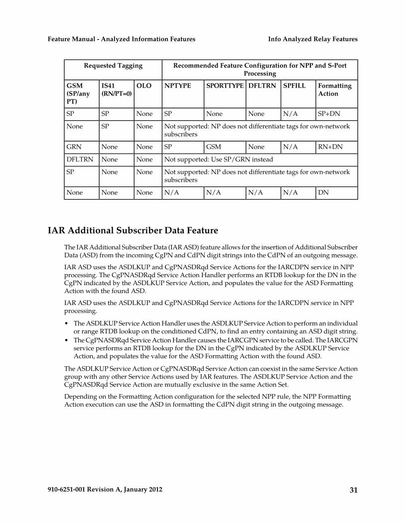
S-Port and NPP Configuration RecommendationsFor features that use Service Portability and the Numbering Plan Processor (NPP), feature-specificconfiguration options, EPAP, and EAGLE 5 ISS data and NPP Formatting Actions work together toproduce the “routing tag” that is used to modify digits in applicable messages. A “routing tag” is theNumber Portability or Service Portability digits chosen to prefix the DN. Own-network GSM and IS41subscribers can be tagged with the GRN (from EPAP entity data), the DFLTRN configuration optionvalue, SP (EPAP entity digits), or no tag. OLO subscribers can be tagged with the RN (EPAP entitydigits) or no tag.
Table 6: Recommended NPP Provisioning for "Routing Tags" indicates the recommended provisioningfor features that use NPP, based on how the subscriber numbers will be tagged. Service Portabilityprovides the capability to use the GRN to tag own-network GSM and IS41 subscribers. A few potentialcombinations are not supported, because standard Number Portability processing does not differentiatebetween GSM and IS41 subscribers.
The following acronyms are used in the table header for feature-specific configuration options. Theoption names are not the same across all features that use NPP, but all NPP features do provide asimilar option:
• NPTYPE - determines lookup success criterion• SPORTTYPE - determines which own-network subscribers to tag with the GRN prefix (IS41, GSM,
all, or none)• DFLTRN – specifies feature-specific value for a default Routing Number• SPFILL – specifies whether NPP should populate both SP and RN Formatting Action values even
when DFLTRN or GRN is being used for local subscribers. In some scenarios, setting SPFILL toYES can cause double digits to be present. IS41 digits (RN/PT=0) are considered SP, because theyshould contain an E.164 HLR ID.
Because S-Port Subscriber Differentiation operates within the Service Portability call flow, when bothare on and Service Portability is applicable, then ASD digits are used, if provisioned, in place of GRNdigits. If ASD digits are not provisioned, then standard Service Portability processing is used. WhereverGRN appears in Table 6: Recommended NPP Provisioning for "Routing Tags", provisioned ASD digitswill be used if S-Port Subscriber Differentiation and Service Portability are ON.
29910-6251-001 Revision A, January 2012
Info Analyzed Relay FeaturesFeature Manual - Analyzed Information Features

Table 6: Recommended NPP Provisioning for "Routing Tags"
Recommended Feature Configuration for NPP and S-PortProcessing
Requested Tagging
FormattingAction
SPFILLDFLTRNSPORTTYPENPTYPEOLOIS41(RN/PT=0)
GSM(SP/anyPT)
RN+DNN/AN/AALLRNSPRNGRNGRN
RN+DNN/ADFLTRNIS41RNSPRNGRNDFLTRN
RN+SP+DNNoNoneIS41RNSPRNGRNSP
RN+DNN/ANoneIS41RNSPRNGRNNone
RN+DNN/ADFLTRNGSMRNSPRNDFLTRNGRN
RN+DNN/ADFLTRNNoneRNSPRNDFLTRNDFLTRN
Not supported: Use SP/GRN insteadRNDFLTRNSP
Not supported: Use None/GRN insteadRNDFLTRNNone
RN+SP+DNNoNoneGSMRNSPRNSPGRN
Not supported: Use GRN/SP insteadRNSPDFLTRN
RN+SP+DNN/ANoneNoneRNSPRNSPSP
Not supported: NP does not differentiate tags for own-networksubscribers
RNSPNone
RN+DNN/ANoneGSMRNSPRNNoneGRN
Not supported: Use GRN/NoneRNNoneDFLTRN
Not supported: NP does not differentiate tags for own-networksubscribers
RNNoneSP
RN+DNN/AN/AN/ARNRNNoneNone
RN+DNN/AN/AALLSPNoneGRNGRN
RN+DNN/ADFLTRNIS41SPNoneGRNDFLTRN
RN+SP+DNNoNoneIS41SPNoneGRNSP
RN+DNN/ANoneIS41SPNoneGRNNone
RN+DNN/ADFLTRNGSMSPNoneDFLTRNGRN
RN+DNN/ADFLTRNNoneSPNoneDFLTRNDFLTRN
Not supported: Use SP/GRN insteadNoneDFLTRNSP
Not supported: Use None/GRN insteadNoneDFLTRNNone
RN+SP+DNNoNoneGSMSPNoneSPGRN
Not supported: Use GRN/SP insteadNoneSPDFLTRN
30910-6251-001 Revision A, January 2012
Info Analyzed Relay FeaturesFeature Manual - Analyzed Information Features
Recommended Feature Configuration for NPP and S-PortProcessing
Requested Tagging
FormattingAction
SPFILLDFLTRNSPORTTYPENPTYPEOLOIS41(RN/PT=0)
GSM(SP/anyPT)
SP+DNN/ANoneNoneSPNoneSPSP
Not supported: NP does not differentiate tags for own-networksubscribers
NoneSPNone
RN+DNN/ANoneGSMSPNoneNoneGRN
Not supported: Use SP/GRN insteadNoneNoneDFLTRN
Not supported: NP does not differentiate tags for own-networksubscribers
NoneNoneSP
DNN/AN/AN/AN/ANoneNoneNone
IAR Additional Subscriber Data Feature
The IAR Additional Subscriber Data (IAR ASD) feature allows for the insertion of Additional SubscriberData (ASD) from the incoming CgPN and CdPN digit strings into the CdPN of an outgoing message.
IAR ASD uses the ASDLKUP and CgPNASDRqd Service Actions for the IARCDPN service in NPPprocessing. The CgPNASDRqd Service Action Handler performs an RTDB lookup for the DN in theCgPN indicated by the ASDLKUP Service Action, and populates the value for the ASD FormattingAction with the found ASD.
IAR ASD uses the ASDLKUP and CgPNASDRqd Service Actions for the IARCDPN service in NPPprocessing.
• The ASDLKUP Service Action Handler uses the ASDLKUP Service Action to perform an individualor range RTDB lookup on the conditioned CdPN, to find an entry containing an ASD digit string.
• The CgPNASDRqd Service Action Handler causes the IARCGPN service to be called. The IARCGPNservice performs an RTDB lookup for the DN in the CgPN indicated by the ASDLKUP ServiceAction, and populates the value for the ASD Formatting Action with the found ASD.
The ASDLKUP Service Action or CgPNASDRqd Service Action can coexist in the same Service Actiongroup with any other Service Actions used by IAR features. The ASDLKUP Service Action and theCgPNASDRqd Service Action are mutually exclusive in the same Action Set.
Depending on the Formatting Action configuration for the selected NPP rule, the NPP FormattingAction execution can use the ASD in formatting the CdPN digit string in the outgoing message.
31910-6251-001 Revision A, January 2012
Info Analyzed Relay FeaturesFeature Manual - Analyzed Information Features

IAR Generic Routing Number Feature
The IAR Generic Routing Number (IAR GRN) feature allows for the insertion of Generic RoutingNumber data (GRN) from the incoming CgPN and CdPN digit strings into the CdPN of an outgoingmessage.
IAR GRN uses the GRNLKUP and CgPNGRNRqd Service Actions for the IARCDPN service in NPPprocessing.
• The GRNLKUP Service Action Handler uses the GRNLKUP Service Action to perform an individualor range RTDB lookup on the conditioned CdPN, to find an entry containing a GRN digit string.
• The CgPNGRNRqd Service Action Handler causes the IARCGPN service to be called. The IARCGPNservice performs an RTDB lookup for the DN in the CgPN indicated by the GRNLKUP ServiceAction, and populates the value for the GRN Formatting Action with the found GRN.
The GRNLKUP Service Action or CgPNGRNRqd Service Action can coexist in the same Service Actiongroup with any other Service Actions used by IAR features. The GRNLKUP Service Action and theCgPNGRNRqd Service Action are mutually exclusive in the same Action Set.
Depending on the Formatting Action configuration for the selected NPP rule, the NPP FormattingAction execution can use the GRN in formatting the CdPN digit string in the outgoing message.
IAR-Related Feature Processing
Every IAR Service Action depends upon one or more features. Some feature status checking isperformed at provisioning time. Many of the IAR-related features may be turned ON and OFF at anytime. All SA that are associated with features other than the IAR Base check the ON/OFF status ofthose features at run-time.
With all IAR-related features ON, Service Actions can perform NP, extract ASD data from the RTDB,invoke the IARCGPN service, and reformat the CdPN. However, if the IAR NP feature is OFF thenNumber Portability processing is not performed. Likewise, if the IAR ASD feature is OFF then theASDLKUP SA has no effect. Turning OFF a feature can also have the side-effect of disabling use ofthe IARCGPN service.
The Service Portability (S-Port) feature affects only the CDPNNP Service Action and that ServiceAction depends upon the IAR NP feature. S-Port processing applies only when both S-Port featureand the IAR NP feature are ON. Although the S-Port feature may be ON, S-Port processing is ignoredwhen the IAR NP feature status is OFF.
S-Port Subscriber Differentiation feature processing occurs only when the IAR NP feature is on, theService Portability feature and option are on, the S-Port Subscriber Differentiation feature and optionare on, and Service Portability is applicable.
32910-6251-001 Revision A, January 2012
Info Analyzed Relay FeaturesFeature Manual - Analyzed Information Features

IAR-Related Features Configuration Options
The TATROPTS table contains configuration option values for the IAR-related features, and the ServicePortability feature when it is used with IAR NP. The TATROPTS option data is loaded to the LIMcards and to Service Module cards that contain the RTDB database. The configuration option valuesinfluence number conditioning, response message formatting and generation, and Service Portabilityprocessing.
TATROPTS options can be provisioned after the IAR Base feature is enabled and before the feature isturned on.
Table 7: TATROPTS Configuration Options describes the TATROPTS options.
Table 7: TATROPTS Configuration Options
NotesDescriptionValueParameter
Service ProviderSPCDNPTYPE - Entitytype for CdPN RTDB Routing NumberRNlookup performed byIAR NP. Routing Number or
Service ProviderRNSP
Specifies the CdPNentity type for which RN, SP, or match with
any entityANYMATCH
the lookup is considereda success. The lookup is always
considered successful.ALWAYS
RN, SP, or DNRNSPDN
Service ProviderSPCGNPTYPE - CgPNentity type for RTDB Routing NumberRNlookup performed byIAR NP. Routing Number or
Service ProviderRNSP
Specified the CgPNentity type for which RN, SP, or match with
any entityANYMATCH
the lookup is considereda success. The lookup is always
considered successful.ALWAYS
Always check for theDEFCC value
ALWAYSCGPACCCK - CgPACountry Code Check
The value refers to theNational Indicator bit in
Check for the DEFCCvalue if the CDPN NAIis not International.
NONINTLSpecifies whether IARBase checks theincoming CgPA for the Nature of Number
file of the CdPNpresence of the countryparameter. The check iscode defined in theperformed only whenSTPOPTS DEFCC
option. the National Indicator
33910-6251-001 Revision A, January 2012
Info Analyzed Relay FeaturesFeature Manual - Analyzed Information Features

NotesDescriptionValueParameter
bit in the Nature ofNumber field of theCdPN is not INTL.
The DEFCC check is notperformed.
OFF
1-15 hex digitsDFLTRN - DefaultRouting Number A default RN is not
used.NONE
Specifies the default RNthat is used when avalue of SP or RNSP isspecified for theCDNPTYPE orCGNPTPE parameter,and the CdPN or CgPNRTDB lookup findsentity type SP.
Can be provisioned onlywhen the IAR Base, IAR
Service Portability is notperformed for IAR NP.
NONESPORTTYPE - ServicePortability Type NP, and Service
Apply ServicePortability prefix (RTDB
GSMSpecifies whetherService Portability is
Portability features areenabled.
GRN entity ID) forperformed for thefeature. own-network GSM
subscribers
Apply ServicePortability prefix (RTDB
IS41
GRN entity ID) forown-network IS41subscribers
Apply ServicePortability prefix (GRN
ALL
from RTDB entity) forall own-networksubscribers
Destination-based Configuration Options for IAR Pre-NPP Processing
The Destination table can contain an IAR-related option value for destination point codes. TheHOMESCP option contains a flag that is used by IAR pre-NPP processing for messages with GTI=0to determine if the associated full point code is for a Home SCP.
See EAGLE 5 ISS Commands and the Commands Manual for a description of the destination-based optionfor IAR and the EAGLE 5 ISS commands that are used to configure the option.
34910-6251-001 Revision A, January 2012
Info Analyzed Relay FeaturesFeature Manual - Analyzed Information Features

SCCP Options Configuration Option for S-Port Subscriber Differentiation
The SCCPOPTS SUBDFRN option turns the S-Port Subscriber Differentiation function on and off inthe system. The S-Port Subscriber Differentiation feature must be enabled and turned on before theoption can be provisioned..
See EAGLE 5 ISS Commands and the Commands Manual for a description of the SCCPOPTS SUBDFRNoption and the EAGLE 5 ISS chg/rtrv-sccpopts commands that are used to configure the option.
EAGLE 5 ISS Commands
This section describes commands that can be used for the configuration of the Info AnalyzedRelay-related features.
Refer to the Commands Manual for complete descriptions of the following commands, includingparameter names, valid values, and output examples for the commands.
Table 8: Commands used for IAR-Related Features
CommandsType
ent/rtrv-serial-numSystem Serial Number
ent/dlt/rtrv/alw/inh/init/rept-stat-cardCard
ent/chg/dlt/rtrv-npp-as,ent/chg/dlt/rtrv-npp-srs, chg/rtrv-npp-serv
Numbering Plan Processor (NPP)
chg/rtrv-stpoptsSTP Options
chg/rtrv-feat, enable/chg/rtrv-ctrl-featFeature Control
chg/dlt/ent/rtrv-srvselService Selector
chg/rtrv-cslCommon Screening List
chg/rtrv-tatroptsTATR Options
chg/rtrv-sccpoptsSCCP Options
ent/chg/dlt/rtrv-dstnDestination Option
chg/rtrv-tatr-msg, tst-msgTest Tool
ent/chg/dlt/rtrv-npp-as, ent/chg/dlt/rtrv-npp-srs, chg/rtrv-npp-serv
The NPP commands are used to provision and display the values for components that are used inNPP processing.
35910-6251-001 Revision A, January 2012
Info Analyzed Relay FeaturesFeature Manual - Analyzed Information Features

chg/rtrv-stpopts
The STP Options commands are used to provision system options for the EAGLE 5 ISS. The optionsare used to control system-level processing. Features can check the option values to determine whatprocessing to apply. The IAR-related features and the ANSIGFLEX option cannot be used together inthe same system. The DEFCC option defines the Default Country Code, which is used in the CgPADEFCC Check to identify message from the home network that should not be modified.
enable/chg/rtrv-ctrl-feat
These commands are used to enable, turn on, and display the on/off status of IAR-related featuresand the Service Portability feature.
ent/dlt/chg/rtrv-srvsel
The service selector commands are used to provision and display service selector information for thettr service that is used by the IAR Base feature.
ent/chg/dlt/rtrv-csl
Common Screening List commands are used to define, change, and display screening requirementsof various features. The screenings are performed on digit strings. For the IAR Base feature, 3 screeninglists are used. Each screening list is based on digit strings.
• GT screening list - The SCCP CdPA is compared to this list to determine if IAR Base featureprocessing should be applied to the message. If not found, the message is dismissed.
• CCNC screening list - The conditioned TCAP DN in international format is compared to this list.If not found, the message is dismissed.
• TRIG screening list - The TRIGTYPE from the incoming message is compared to this list. If notfound, the message is dismissed.
chg/rtrv-tatropts
The TATR Options commands are used to provision the configuration options for the IAR Base, IARNP, and Service Portability features. The options control number portability, Service Portability, andNPP processing for incoming messages and formatting of response messages.
chg/rtrv-sccpopts
The SCCP Options commands are used to provision SCCP options for the EAGLE 5 ISS. The SUBDFRNoption is used to turn on and off the S-Port Subscriber Differentiation function.
ent/chg/dlt/rtrv-dstn
The destination commands are used to provision destination point codes (DPCs). The IAR Base featureuses the flag that is set by the homescp=yes parameter to identify a DPC as a Home SCP.
chg/rtrv-tatr-msg, tst-msg
The chg/rtrv-tatr-msg commands are used to enter and display up to 10 test messages in theTESTMSG table. The messages can be sent by the tst-msg command to the provisioned IAR Basefeature to verify call flow.
36910-6251-001 Revision A, January 2012
Info Analyzed Relay FeaturesFeature Manual - Analyzed Information Features

Chapter
3ANSI41 AnalyzedInformation Query - no EPAP/ELAP
Feature
This chapter describes the ANSI41AnalyzedInformation Query - no EPAP/ELAP
Topics:
• Feature Description.....38 feature (ANSI41 AIQ). The ANSI41 AIQ feature• ANSI41 AIQ Feature Configuration Options....43 allows an operator to migrate customers from one
technology to another (such as CDMA to LTE).• EAGLE 5 ISS Commands.....48
37910-6251-001 Revision A, January 2012

Feature Description
When an operator is moving (migrating) customers from one technology to another technology (suchas CDMA to LTE), the ANSI41 AnalyzedInformation Query - no EPAP/ELAP (ANSI41 AIQ) featureprovides the ability to indicate which calls are destined for a particular technology.
• The Home MSC receives a call for its subscriber, and queries the HLR for call treatment instructions.• Calls that are marked in the HLR will have a termination trigger provided to the Home MSC.
• The HLR provides a termination trigger to the Home MSC.• The Home MSC sends an AnalyzedInformation Query to the EAGLE 5 ISS.• The EAGLE 5 ISS normally responds with an AnalyzedInformation Return Result message with
routing information.• Based on the response, the Home MSC continues with the traditional call set-up procedure.
• If no termination trigger is provided, the Home MSC sends these calls directly to the newertechnology.
ANSI41 AIQ is implemented as a local SCCP subsystem in the EAGLE 5 ISS. ANSI41 AIQ does notrequire connection to, or a Real Time Database (RTDB) from, an EPAP or ELAP. ANSI41 AIQ performsthe following operations:
• Process TCAP_Query_with_Permission AnalyzedInformation queries routed to the ANSI41 AIQfeature.
• Respond with an AnalyzedInformation Return Result message, including the routing informationin the “Routing Digits or Digits (Dialed)” parameter. Configuration options indicate which parameterto include and the format of the parameter in the response message.
AnalyzedInformation Message Flow
Figure 1: EAGLE 5 ISS AnalyzedInformation Message Flow illustrates the EAGLE 5 ISSAnalyzedInformation message flow for the ANSI41 AIQ feature.
Figure 1: EAGLE 5 ISS AnalyzedInformation Message Flow
Figure 2: EAGLE 5 ISS AnalyzedInformation Message Flow Details shows a more detailed message flow.
38910-6251-001 Revision A, January 2012
ANSI41 AnalyzedInformation Query - noEPAP/ELAP Feature
Feature Manual - Analyzed Information Features

Figure 2: EAGLE 5 ISS AnalyzedInformation Message Flow Details
The AIQ Local Subsystem
The AIQ local subsystem receives an incoming MSU, decodes the required data, and generates aresponse MSU based on decoded information and desired response format.
The AIQ local subsystem in the EAGLE 5 ISS processes AnalyzedInformation Query messages (ANSIMTP/SCCP and ITU MTP/SCCP with ANSI TCAP). SCCP UDT and non-segmented XUDT, Class 0or Class 1 messages are supported. Segmented messages (SCCP or TCAP) are not supported. TCAPmust be Query with Permission with Invoke component, and the OpCode must beAnalyzedInformation. The EAGLE 5 ISS responds with an AnalyzedInformation Return Resultincluding provisioned routing information in the Routing Digits or Digits (Dialed) parameter.
Local subsystems in the EAGLE 5 ISS are maintainable entities for query and response that are usedwhen the STP acts as an SCP. Every local SCCP subsystem includes generic SCCP subsystem capabilities.The following function descriptions provide information that is generic to every local subsystem, andindicate the information that is specific to the AIQ local subsystem:
• Common EAGLE 5 ISS provisioning
Capability point codes (CPCs) can be defined for routing to local subsystems independently of theSTP. For AIQ, the EAGLE 5 ISS supports ANSI, ITU-I, ITU-N, ITU-I Spare, and ITU-N Sparecapability point code (CPC) types. ITU-N24 capability point codes are not supported. Capabilitypoint codes for the AIQ local subsystem can be configured only after the ANSI41 AIQ feature isenabled.
The AIQ local subsystem must have a mate subsystem and a concerned point code group assignedto it in the MAP table.The ANSI41 AIQ feature must be enabled before the AIQ local subsystementry can be entered in the MAP table. The AIQ local subsystem can be configured in only Dominantor Solitary loadsharing mode (end nodes do not perform loadsharing).
• Routing Indicator-based message handling
39910-6251-001 Revision A, January 2012
ANSI41 AnalyzedInformation Query - noEPAP/ELAP Feature
Feature Manual - Analyzed Information Features

Messages for the AIQ local subsystem can arrive Rt-on-SSN or Rt-on-GT. All MSUs must containeither the EAGLE 5 ISS true or secondary point code (TSPC), or the AIQ capability point code(CPC), in the DPC field of the message.
• Network Management
The EAGLE 5 ISS must reply to network management queries about the current state of the localsubsystem. The response to each query type is based on the status of the local subsystem.
Table 9: Network Management Response
Action when Local Subsystemis Offline
Action when Local Subsystemis Online
Message
No replyTFARSP (CPC)
TFPTFARSR (CPC) (not supported forITU networks)
TFATFARSP (TSPC)
TFATFARSR (TSPC)
No replySSASST
No replySNRSRT (ANSI only; for ITU, UIM1058: SCCP rcvd inv SCMG- bad msg type isgenerated)
• Network Broadcast.
When the local subsystem changes state, network management messages are sent to the CSPCgroup.
• SNR/SBRs are sent in ANSI networks to the mate node.• SSP/SSAs are sent in ANSI and ITU networks to all nodes in the CSPC group.
• Controls and States
The AIQ local subsystem can be taken online and offline using the coordinated state change, orforced offline without using the coordinated state change, using the procedures in Provisioning theAIQ Local Subsystem.
When a command is entered to perform a coordinated state change, SCCP Management (SCMG)sends an SOR message to the mated subsystem and will start a Tcoord timer (30 seconds). If SCMGreceives an SOG message from the mated subsystem before the Tcoord timer expires, SCMGbroadcasts SSPs to the concerned point code group, sends SBR/SSP, and takes the subsystemoffline. A UAM will be generated notifying that a particular local system is not available andindicating that the subsystem is PROHIBITED. If the SOG is not received before the Tcoord timerexpires, then the inhibit request is denied. A UIM will be generated indicating failure in inhibitinga particular local subsystem.
When a command is entered to take the subsystem offline without using a coordinated state change,the EAGLE 5 ISS just sends SBR/SSPs. A UAM will be generated notifying that a particular localsubsystem is not available and indicating that the subsystem is PROHIBITED.
40910-6251-001 Revision A, January 2012
ANSI41 AnalyzedInformation Query - noEPAP/ELAP Feature
Feature Manual - Analyzed Information Features

When a command is entered to take the local subsystem online (regardless of how the subsystemwas taken offline), the EAGLE 5 ISS sends SNR/SSA. A UAM will be generated notifying that aparticular local subsystem is available and indicating that the subsystem is ALLOWED.
When the EAGLE 5 ISS receives an SOR message from its mated subsystem, it will reply with anSOG message if both of the following conditions are met. If either of the conditions is not met, theEAGLE 5 ISS does not reply to the SOR message.
• The local subsystem is available.• The total load on the local subsystem is less than 45% of its capacity.
• SCMG Functions on LIM Cards
Table 10: LIM Card Processing When Service Module Card is Unavailable shows a summary of actionson the LIM cards when the cards are unable to deliver MSUs to Service Module cards.
Note: For Rt-on GT cases, UDTS generation is qualified by two conditions in the incoming MSU:1) CgPA RI = Rt-on-SSN and 2) message handling = Return message on Error.
* The condition of some Service Module cards being available but overloaded is considered to bea partial failure.
Table 10: LIM Card Processing When Service Module Card is Unavailable
NetworkManagement
MessageHandling (seeNote)
LocalSubsystemStatus
Full or PartialFailure
DPCRoutingIndicator inIncomingMessage
For ANSI -TFP
GenerateUDTS
�FullCPCRt-on-GT
concerningCPC
For ITU - UPUand TFPconcerningCPC
UPUGenerateUDTS
�FullTSPCRt-on-GT
NoneGenerateUDTS
�FullCPCRt-on-SSN
SSPconcerningTSPC
GenerateUDTS
�FullTSPCRt-on-SSN
NoneGenerateUDTS
OnlinePartial *LSS CPCRt-on-GT
NoneGenerateUDTS
OnlinePartial *TSPCRt-on-GT
41910-6251-001 Revision A, January 2012
ANSI41 AnalyzedInformation Query - noEPAP/ELAP Feature
Feature Manual - Analyzed Information Features

NetworkManagement
MessageHandling (seeNote)
LocalSubsystemStatus
Full or PartialFailure
DPCRoutingIndicator inIncomingMessage
NoneGenerateUDTS
OnlinePartial *LSS CPCRt-on-SSN
NoneGenerateUDTS
OnlinePartial *TSPCRt-on-SSN
TFPconcerningCPC
GenerateUDTS
OfflinePartial *LSS CPCRt-on-GT
NoneGenerateUDTS
OfflinePartial *TSPCRt-on-GT
NoneGenerateUDTS
OfflinePartial *LSS CPCRt-on-SSN
SSPconcerningTSPC
GenerateUDTS
OfflinePartial *TSPCRt-on-SSN
NoneGenerateUDTS
�Partial *Non-AIQ CPCRt-on-GT
NoneGenerateUDTS
�Partial *Non-AIQ CPCRt-on-SSN
• MSU decoding (MTP3/SCCP/TCAP decoding) and decode error handling
Common MSU decoding aspects of local SCCP subsystems include decoding MTP3, SCCP, andTCAP portions. Individual local SCCP subsystems decode only the specific TCAP parameters asneeded by the subsystem.
For the AIQ local subsystem, the operation code, Digits (Dialed), and TriggerType in the TCAPComponent of the incoming AnalyzedInformation message are decoded.
If the ANSI41 AIQ feature is enabled and on, the incoming message is decoded to verify that theoperation code is AnalyzedInformation and that valid TriggerType and Digits (Dialed) parametersare present.
• A Return Error response is generated if the operation code is not AnalyzedInformation. A UIMis generated.
• A Reject response is generated if one or more of the parameters are not present. A UIM isgenerated.
• A Return Error response for a TCAP Error or a Reject response is generated if one or more ofthe parameters are not valid. A UIM is generated.
• Some malformed messages shall not generate any response; a UIM can be generated.
If the ANSI41 AIQ feature is enabled but turned off when an AnalyzedInformation message isreceived, a TCAP Error response will be generated with error code "AnalyzedInformation notallowed". No UIM will be generated. If any message other than AnalyzedInformation is received,a UIM is generated and a reply MSU is sent.
42910-6251-001 Revision A, January 2012
ANSI41 AnalyzedInformation Query - noEPAP/ELAP Feature
Feature Manual - Analyzed Information Features

Refer to the Unsolicited Alarm and Information Messages manual for descriptions of the UIMs thatcan be generated for local subsystems. AIQ Local Subsystem UIMs describes the UIMs that are usedspecifically for the AIQ subsystem.
• Response MSU Encoding (MTP3/SCCP/TCAP encoding)
The AnalyzedInformation operation success is reported with a TCAP RETURN RESULT (LAST)response.
If the ANSI41 AIQ feature is enabled and on, and the incoming AnalyzedInformation messagecontains valid TriggerType and Digits (Dialed) parameters, an AnalyzedInformation Return Resultmessage is generated. The AIQOPTS RESFMT and RESPAR configuration options indicate whetherto include RoutingDigits or Digits (Dialed) parameters in the response, and the format of theincluded parameters.
• AIQ-specific Response Encoding Errors
A UIM is generated to indicate truncation of a parameter in the response message when formattingresulted in too many digits in the parameter. The response message is sent with digits truncatedto the maximum allowed number.
A UIM is generated when the CdPA or CgPA cannot be encoded in the response.
ANSI41 AIQ Feature Configuration Options
The AIQOPTS table contains configuration option values for the ANSI41 AIQ feature. The AIQOPTSoption data is loaded to the LIM cards. The configuration option values influence number conditioningand response message formatting and generation.
AIQOPTS options can be provisioned after the ANSI41 AIQ feature is enabled and before the featureis turned on.
Table 11: AIQOPTS Configuration Options describes the AIQOPTS options.
Table 11: AIQOPTS Configuration Options
DescriptionValueParameter
Maximum length of the digitstring that will be considered
1-32DIGMAXLEN - Digits (Dialed)Parameter Maximum DigitLength valid in the Digits (Dialed)
parameter of anAnalyzedInformation query.
The specified value must beequal to or greater than thespecified minimum length of thedigit string (DIGMINLEN).
Digit strings with a number ofcharacters equal to or greaterthan the specified minimumlength and equal to or less than
43910-6251-001 Revision A, January 2012
ANSI41 AnalyzedInformation Query - noEPAP/ELAP Feature
Feature Manual - Analyzed Information Features

DescriptionValueParameter
the specified maximum lengthare considered to be valid duringMSU processing.
A digit string with more than thespecified maximum number ofcharacters generates an errorresponse and a UIM.
If the same value is specified forthe minimum and maximumdigit string length, only digitstrings of that exact length areconsidered to be valid duringMSU processing.
System Default = 32.
Minimum length of the digitstring that will be considered
1-32DIGMINLEN - Digits (Dialed)Parameter Minimum DigitLength valid in the Digits (Dialed)
parameter of anAnalyzedInformation query.
The specified value must beequal to or less than the specifiedmaximum length of the digitstring (DIGMAXLEN).
Digit strings with a number ofcharacters equal to or greaterthan the specified minimumlength and equal to or less thanthe specified maximum lengthare considered to be valid duringMSU processing.
A digit string with less than thespecified minimum number ofcharacters or with no digitsgenerates an error response anda UIM.
System Default = 1.
Mandatory when a TRIGTYPEparameter value is specified.
1-21 hexadecimal digits, NONEPFX - Digit string associatedwith a TRIGTYPE parametervalue The value NONE indicates that
the corresponding TRIGTYPEvalue is not provisioned. Thecorresponding TRIGTYPE valuewill not be displayed in the
44910-6251-001 Revision A, January 2012
ANSI41 AnalyzedInformation Query - noEPAP/ELAP Feature
Feature Manual - Analyzed Information Features

DescriptionValueParameter
rtrv-aiqopts commandoutput.
Specifies that the provisionedPFX parameter value that
PFXRESFMT - Response Format
corresponds to the TRIGTYPEvalue (the Trigger Type valuereceived in theAnalyzedInformation query) willbe encoded in theAnalyzedInformation ReturnResult message.
Specifies that the provisionedPFX parameter value + the
PFXDN
incoming Digits (Dialed) will beencoded in theAnaluzedInformation ReturnResult message.
This is the System Default.
Specifies that the RoutingDigitsparameter will be used when
RTDIGITSRESPAR - Response Parameter
encoding theAnalyzedInformation ReturnResult message.
This is the System Default.
Specifies that the Digits (Dialed)parameter will be used when
DIGITS
encoding theAnalyzedInformation ReturnResult message.
The specified TCAP error codeis used in the Return Errorresponse when:
129-255
See Table 12: TCAP Error Codesand Corresponding Error Strings.
TCAPERR - TCAP error code tobe returned in the Return Errorresponse message
• The TRIGTYPE parameter isnot provisioned for theTrigger Type value receivedin the incomingAnalyzedInformation query.
• The length of the Digits(Dialed) parameter is notwithin the provisioned rangeof minimum and maximum
45910-6251-001 Revision A, January 2012
ANSI41 AnalyzedInformation Query - noEPAP/ELAP Feature
Feature Manual - Analyzed Information Features

DescriptionValueParameter
length (DIGMINLEN andDIGMAXLEN)
The System Default is 138.
An individual trigger.0-255TRIGTYPE - Trigger Type
Each TRIGTYPE value isassociated with a PFX digitstring.
See Table 13: Trigger Type(TRIGTYPE) Values and theirMeanings.
The TRIGTYPE parameter mustbe specified when the PFXparameter is specified.
A maximum of 20TRIGTYPE-PFX pairs can bedefined.
Table 12: TCAP Error Codes and Corresponding Error Strings lists the Corresponding Error Strings forthe TCAP Error Codes that can be specified using the TCAPERR option.
Table 12: TCAP Error Codes and Corresponding Error Strings
Error StringTCAP Error Code
UnrecognizedMIN129
UnrecognizedESN130
MIN/HLRMismatch131
OperationSequenceProblem132
ResourceShortage133
OperationNotSupported134
TrunkUnavailable135
ParameterError136
SystemFailure137
UnrecognizedParameterValue138
FeatureInactive139
MissingParameter140
Reserved141-239
Reserved for Protocol Extension240-255
Table 13: Trigger Type (TRIGTYPE) Values and their Meanings lists supported Trigger Type (TRIGTYPE)values and their meanings.
46910-6251-001 Revision A, January 2012
ANSI41 AnalyzedInformation Query - noEPAP/ELAP Feature
Feature Manual - Analyzed Information Features

Table 13: Trigger Type (TRIGTYPE) Values and their Meanings
MeaningTrigger TypeValue
Unspecified.0
All_Calls.1
Double_Introducing_Star.2
Single_Introducing_Star.3
Reserved [for Home_System_Feature_Code]4
Double_Introducing_Pound.5
Single_Introducing_Pound.6
Revertive_Call.7
0_Digit.8
1_Digit.9
2_Digit.10
3_Digit.11
4_Digit.12
5_Digit.13
6_Digit.14
7_Digit.15
8_Digit.16
9_Digit.17
10_Digit.18
11_Digit.19
12_Digit.20
13_Digit21
14_Digit.22
15_Digit.23
Local_Call.24
Local_Toll_Call.25
Non-Local_Toll_Call.26
World_Zone_Call.27
International_Call.28
47910-6251-001 Revision A, January 2012
ANSI41 AnalyzedInformation Query - noEPAP/ELAP Feature
Feature Manual - Analyzed Information Features

MeaningTrigger TypeValue
Unrecognized_Number.29
Prior_Agreement.30
Specific_Called_Party_Digit_String.31
Mobile_Termination.32
Advanced_Termination.33
Location.34
Reserved. Treat a reserved value the same as value 0, Unspecified.35-63
Terminating_Resource_Available.64
T_Busy.65
T_No_Answer.66
T_No_Page_Response.67
T_Unroutable.68
Reserved. Treat a reserved value the same as value 0, Unspecified.69-219
Reserved for TDP-R DP value.220
Reserved for TDP-N DP value.221
Reserved for EDP-R DP value.222
Reserved for EDP-N DP value.223
Reserved for TIA-41 protocol extension. If unknown, treat the same as value 0,Unspecified.
224-255
EAGLE 5 ISS Commands
Table 14: EAGLE 5 ISS Commands used for the ANSI41 AIQ Feature lists the EAGLE 5 ISS commands thatare used for configuration for the ANSI41 AnalyzedInformation (ANSI41 AIQ) feature.
Refer to the Commands Manual for complete descriptions of the commands, including parameter names,valid parameter values, and output examples.
Table 14: EAGLE 5 ISS Commands used for the ANSI41 AIQ Feature
CommandsType
The chg/rtrv-feat commands are used to turnon and display the on/off status of features thatare controlled with feature bits.
Feature Control
48910-6251-001 Revision A, January 2012
ANSI41 AnalyzedInformation Query - noEPAP/ELAP Feature
Feature Manual - Analyzed Information Features
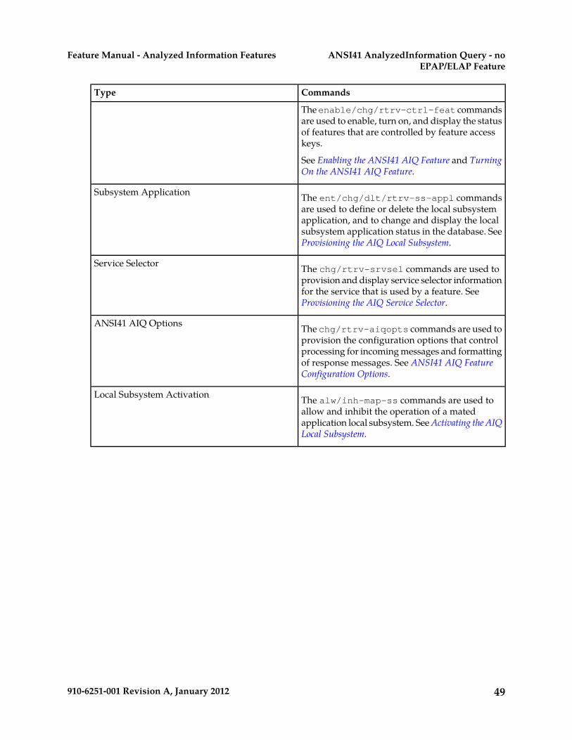
CommandsType
The enable/chg/rtrv-ctrl-feat commandsare used to enable, turn on, and display the statusof features that are controlled by feature accesskeys.
See Enabling the ANSI41 AIQ Feature and TurningOn the ANSI41 AIQ Feature.
The ent/chg/dlt/rtrv-ss-appl commandsare used to define or delete the local subsystem
Subsystem Application
application, and to change and display the localsubsystem application status in the database. SeeProvisioning the AIQ Local Subsystem.
The chg/rtrv-srvsel commands are used toprovision and display service selector information
Service Selector
for the service that is used by a feature. SeeProvisioning the AIQ Service Selector.
The chg/rtrv-aiqopts commands are used toprovision the configuration options that control
ANSI41 AIQ Options
processing for incoming messages and formattingof response messages. See ANSI41 AIQ FeatureConfiguration Options.
The alw/inh-map-ss commands are used toallow and inhibit the operation of a mated
Local Subsystem Activation
application local subsystem. See Activating the AIQLocal Subsystem.
49910-6251-001 Revision A, January 2012
ANSI41 AnalyzedInformation Query - noEPAP/ELAP Feature
Feature Manual - Analyzed Information Features

Chapter
4Feature Configuration
This chapter provides procedures for configuringthe IAR-related features for use in the EAGLE 5 ISS.
Topics:
• Introduction.....51 Procedures are included for configuration of the• IAR-Related Features Configuration.....52 Service Portability feature and the S-Port Subscriber
Differentiation feature for use with the IAR NPfeature.
• Service Portability Feature ConfigurationProcedures.....66
This chapter also provides procedures forconfiguring the ANSI41 AIQ feature.
• S-Port Subscriber Differentiation FeatureConfiguration Procedures.....69
• ANSI41 AIQ Configuration.....72• Adding a Service Module Card.....85• The 1100 TPS/DSM for ITU NP Feature.....92• Activating the E5-SM4G Throughput Capacity
Feature.....96
50910-6251-001 Revision A, January 2012

Introduction
This chapter describes prerequisites and procedures for the EAGLE 5 ISS configuration of the followingfeatures:
• IAR-related features (IAR Base, IAR NP, IAR ASD, IAR GRN)
• The Service Portability feature and the S-Port Subscriber Differentiation feature for use with theIAR NP feature
• The ANSI41 AIQ feature
Each section includes a configuration procedure that lists the steps for enabling and turning on eachfeature, and for the provisioning required for the features. Each step contains a link or reference toinformation and procedures to use to complete the step. Feature provisioning can be performed afterthe features are enabled and before the features are turned on.
Note: Controlled features are optional and must be purchased from Tekelec before they can be usedin your system. If you are not sure whether you have purchased a specific feature, contact your TekelecSales or Account Representative.
System Prerequisites
Before any feature that is described in this manual can be enabled, the prerequisites listed in Table 15:System Prerequisites are required in the system.
Table 15: System Prerequisites
Verification and ProvisioningPrerequisite
Note: The serial number cannot be changed afterit is entered and locked in the system.
The system serial number must be correct andlocked.
For new installations, the system is shipped withan unlocked serial number. The serial number can
Locate the serial number for the system on a labelaffixed to the control shelf (1100).
be changed if necessary and must be locked afterthe system is on-site. Enter the rtrv-serial-num command to
display the serial number and its locked status.For systems that are being upgraded, the serialnumber is usually already verified and locked. Verify that the displayed serial number is correct
for the system.
If no serial number is displayed, enter theent-serial-num command (without the lockparameter) to provision the serial number thatappears on the control shelf label. Enter thertrv-serial-num command and verify that theserial number was entered correctly.
Enter the ent-serial-num command with thelock=yes parameter to lock the serial number inthe system.
51910-6251-001 Revision A, January 2012
Feature ConfigurationFeature Manual - Analyzed Information Features

Verification and ProvisioningPrerequisite
Enter the rept-stat-card:appl=vsccpcommand to list the Service Module cards in thesystem.
A sufficient number of Service Module cards mustbe equipped.
Some features require only E5-SM4G cards andcannot use DSM cards. See specific featureprerequisites, if any, in this section.
If more cards or cards of a different type areneeded, refer to the procedures in the DatabaseAdministration Manual - GTT to add ServiceModule cards or remove DSM cards.Refer to the Dimensioning Guide for EPAP Advanced
DB Features for information on the dimensioningrules and the database capacity requirements forEPAP-related features.
Enter the rtrv-feat command to display theGTT feature status.
The GTT feature must be on in the system.
Some features require an additional GTT-relatedfeature such as EGTT. See the specific featureprerequisites in this section.
If the GTT feature is on, the gtt=on entry appearsin the output.
If the gtt=off entry appears in the output, use theprocedures in the Database Administration Manual- GTT to turn on and provision the GTT featureand any other GTT-related features and functionsthat will be used in the system.
IAR-Related Features Configuration
The IAR-related features are configured on the EAGLE 5 ISS. This section describes prerequisites andprocedures for the configuration of IAR-related features. This section also describes or providesreferences for configuration of the following features:
• Configuration of the Service Portability feature and the S-Port Subscriber Differentiation featurefor use with the IAR NP feature
• Configuration of the Gateway Screening (GWS) feature and the MTP Routed GWS Stop Actionfeature to filter MTP-routed UDT, UDTS, XUDT, and XUDTS SCCP messages for Service Cardmodule processing
• Configuration of the MTP Routed Messages for SCCP Applications feature to forward allMTP-routed AnalyzedInformation messages for Service Module card processing
Configuration Procedure for IAR-Related Features lists the steps for enabling and turning on the features,and for the provisioning required for the features. Each step contains a link or reference to informationand procedures to use to complete the step. Feature provisioning can be performed after the featuresare enabled and before the features are turned on.
Note: Controlled features are optional and must be purchased from Tekelec before they can be usedin your system. If you are not sure whether you have purchased a specific feature, contact your TekelecSales or Account Representative.
52910-6251-001 Revision A, January 2012
Feature ConfigurationFeature Manual - Analyzed Information Features

IAR-Related Feature Prerequisites
Before any IAR-related feature can be enabled, the following prerequisites are required in the system:
Table 16: IAR-Related Feature Prerequisites
Verification and ProvisioningPrerequisite
Enter the rtrv-stpopts command.The ANSIGFLEX system option cannot be set toYes.
Verify that the ANSIGFLEX entry does not appearin the command output or that the ANSI GFLEXentry shows a value of No.
Enter the rtrv-ctrl-feat command.The LNP feature cannot be on in the system
If the LNP feature is on, shown with a quantitygreater than zero for the LNP ported TNs entryin the command output, features described in thismanual cannot be enabled.
Refer to the procedures in the DatabaseAdministration Manual - Gateway Screening.If the MTP Routing GWS Stop Action feature will
be used to select UDT, UDTS, XDT, and XDTSMTP-routed messages for IAR processing:
• Up to 8 GLS cards must be equipped.• The Gateway Screening feature must be turned
on.• The MTP Routed GWS Stop Action feature
must be enabled and turned on.• The GWS SCCP Stop Action must be
provisioned as the last Stop Action in theAction Set.
• The Gateway Screening gwsa linkset optionmust be turned on for each linkset that will bescreened using the SCCP Stop Action. Thegwsd and gwsm options are not required, butcan be used if desired.
Configuration Procedure for IAR-Related Features
The EAGLE 5 ISS configuration of the Info Analyzed Relay Base (IAR Base) feature and related featuresconsists of the following steps. The steps contain links and references to detailed procedures andinformation needed to complete each step.
1. Verify, and provision if needed, the system prerequisites. See System Prerequisites.2. Verify, and provision if needed, the feature prerequisites. See IAR-Related Feature Prerequisites.
53910-6251-001 Revision A, January 2012
Feature ConfigurationFeature Manual - Analyzed Information Features
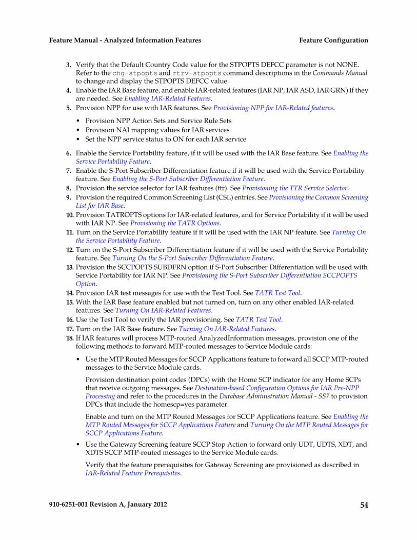
3. Verify that the Default Country Code value for the STPOPTS DEFCC parameter is not NONE.Refer to the chg-stpopts and rtrv-stpopts command descriptions in the Commands Manualto change and display the STPOPTS DEFCC value.
4. Enable the IAR Base feature, and enable IAR-related features (IAR NP, IAR ASD, IAR GRN) if theyare needed. See Enabling IAR-Related Features.
5. Provision NPP for use with IAR features. See Provisioning NPP for IAR-Related features.
• Provision NPP Action Sets and Service Rule Sets• Provision NAI mapping values for IAR services• Set the NPP service status to ON for each IAR service
6. Enable the Service Portability feature, if it will be used with the IAR Base feature. See Enabling theService Portability Feature.
7. Enable the S-Port Subscriber Differentiation feature if it will be used with the Service Portabilityfeature. See Enabling the S-Port Subscriber Differentiation Feature.
8. Provision the service selector for IAR features (ttr). See Provisioning the TTR Service Selector.9. Provision the required Common Screening List (CSL) entries. See Provisioning the Common Screening
List for IAR Base.10. Provision TATROPTS options for IAR-related features, and for Service Portability if it will be used
with IAR NP. See Provisioning the TATR Options.11. Turn on the Service Portability feature if it will be used with the IAR NP feature. See Turning On
the Service Portability Feature.12. Turn on the S-Port Subscriber Differentiation feature if it will be used with the Service Portability
feature. See Turning On the S-Port Subscriber Differentiation Feature.13. Provision the SCCPOPTS SUBDFRN option if S-Port Subscriber Differentiation will be used with
Service Portability for IAR NP. See Provisioning the S-Port Subscriber Differentiation SCCPOPTSOption.
14. Provision IAR test messages for use with the Test Tool. See TATR Test Tool.15. With the IAR Base feature enabled but not turned on, turn on any other enabled IAR-related
features. See Turning On IAR-Related Features.16. Use the Test Tool to verify the IAR provisioning. See TATR Test Tool.17. Turn on the IAR Base feature. See Turning On IAR-Related Features.18. If IAR features will process MTP-routed AnalyzedInformation messages, provision one of the
following methods to forward MTP-routed messages to Service Module cards:
• Use the MTP Routed Messages for SCCP Applications feature to forward all SCCP MTP-routedmessages to the Service Module cards.
Provision destination point codes (DPCs) with the Home SCP indicator for any Home SCPsthat receive outgoing messages. See Destination-based Configuration Options for IAR Pre-NPPProcessing and refer to the procedures in the Database Administration Manual - SS7 to provisionDPCs that include the homescp=yes parameter.
Enable and turn on the MTP Routed Messages for SCCP Applications feature. See Enabling theMTP Routed Messages for SCCP Applications Feature and Turning On the MTP Routed Messages forSCCP Applications Feature.
• Use the Gateway Screening feature SCCP Stop Action to forward only UDT, UDTS, XDT, andXDTS SCCP MTP-routed messages to the Service Module cards.
Verify that the feature prerequisites for Gateway Screening are provisioned as described inIAR-Related Feature Prerequisites.
54910-6251-001 Revision A, January 2012
Feature ConfigurationFeature Manual - Analyzed Information Features
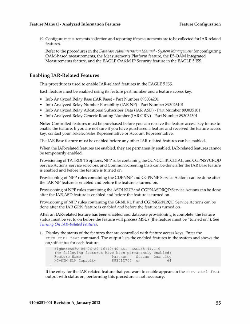
19. Configure measurements collection and reporting if measurements are to be collected for IAR-relatedfeatures.
Refer to the procedures in the Database Administration Manual - System Management for configuringOAM-based measurements, the Measurements Platform feature, the E5-OAM IntegratedMeasurements feature, and the EAGLE OA&M IP Security feature in the EAGLE 5 ISS.
Enabling IAR-Related Features
This procedure is used to enable IAR-related features in the EAGLE 5 ISS.
Each feature must be enabled using its feature part number and a feature access key.
• Info Analyzed Relay Base (IAR Base) - Part Number 893034201• Info Analyzed Relay Number Portability (IAR NP) - Part Number 893026101• Info Analyzed Relay Additional Subscriber Data (IAR ASD) - Part Number 893035101• Info Analyzed Relay Generic Routing Number (IAR GRN) - Part Number 893034301
Note: Controlled features must be purchased before you can receive the feature access key to use toenable the feature. If you are not sure if you have purchased a feature and received the feature accesskey, contact your Tekelec Sales Representative or Account Representative.
The IAR Base feature must be enabled before any other IAR-related features can be enabled.
When the IAR-related features are enabled, they are permanently enabled. IAR-related features cannotbe temporarily enabled.
Provisioning of TATROPTS options, NPP rules containing the CCNCCHK, CDIAL, and CGPNSVCRQDService Actions, service selectors, and Common Screening Lists can be done after the IAR Base featureis enabled and before the feature is turned on.
Provisioning of NPP rules containing the CDPNNP and CGPNNP Service Actions can be done afterthe IAR NP feature is enabled and before the feature is turned on.
Provisioning of NPP rules containing the ASDLKUP and CGPNASDRQD Service Actions can be doneafter the IAR ASD feature is enabled and before the feature is turned on.
Provisioning of NPP rules containing the GRNLKUP and CGPNGRNRQD Service Actions can bedone after the IAR GRN feature is enabled and before the feature is turned on.
After an IAR-related feature has been enabled and database provisioning is complete, the featurestatus must be set to on before the feature will process MSUs (the feature must be “turned on”). SeeTurning On IAR-Related Features.
1. Display the status of the features that are controlled with feature access keys. Enter thertrv-ctrl-feat command. The output lists the enabled features in the system and shows theon/off status for each feature. rlghncxa03w 09-06-29 16:40:40 EST EAGLE5 41.1.0 The following features have been permanently enabled: Feature Name Partnum Status Quantity HC-MIM SLK Capacity 893012707 on 64 ;
If the entry for the IAR-related feature that you want to enable appears in the rtrv-ctrl-featoutput with status on, performing this procedure is not necessary.
55910-6251-001 Revision A, January 2012
Feature ConfigurationFeature Manual - Analyzed Information Features

2. Enable each IAR-related feature, by entering the enable-ctrl-feat command and specify thepart number and feature access key for the feature. The IAR Base feature must be enabled beforeother IAR-related features can be enabled.enable-ctrl-feat:partnum=<893xxxxx>:fak=<feature access key>
When a feature is enabled, the entry for the enabled feature appears in the output of thertrv-ctrl-feat command. The feature Status is off. rlghncxa03w 09-06-29 16:40:40 EST EAGLE5 41.1.0 The following features have been permanently enabled: Feature Name Partnum Status Quantity HC-MIM SLK Capacity 893012707 on 64 Info Analyzed Relay Base 893034201 off ---- Info Analyzed Relay NP 893026101 off ---- IAR ASD 893035001 off ---- IAR GRN 893035101 off ----;
3. Back up the database changes, by entering the following command.chg-db:action=backup:dest=fixed
The following messages appear; the active Maintenance and Administration Subsystem Processor(MASP) appears first.BACKUP (FIXED) : MASP A - Backup starts on active MASP.BACKUP (FIXED) : MASP A - Backup on active MASP to fixed disk complete.BACKUP (FIXED) : MASP A - Backup starts on standby MASP.BACKUP (FIXED) : MASP A - Backup on standby MASP to fixed disk complete.
Provisioning the TTR Service Selector
The procedures in this section describe how to add, change, and remove a service selector. Theinformation is indicated that is specific to IAR-related features.
Refer to the Commands Manual for complete descriptions of the commands used in these procedures,including parameter names, valid values, and output examples for the commands.
Adding a TTR Service SelectorThis procedure is used to add a TTR service selector for the IAR Base feature.
The IAR Base feature must be enabled before a TTR service selector can be added.
1. Verify that the IAR Base feature is enabled, by entering the rtrv-ctrl-feat command.
If the IAR Base feature is enabled, the status of the Info Analyzed Relay Base entry is on. rlghncxa03w 09-06-29 16:40:40 EST EAGLE5 41.1.0 The following features have been permanently enabled: Feature Name Partnum Status Quantity HC-MIM SLK Capacity 893012707 on 64 Info Analyzed Relay Base 893034201 on ----;
• If the IAR Base feature is enabled, continue with Step 2.• If the IAR Base feature is not enabled, go to Enabling IAR-Related Features to enable the IAR Base
feature. Then continue with Step 2.
56910-6251-001 Revision A, January 2012
Feature ConfigurationFeature Manual - Analyzed Information Features

2. Display any existing TTR service selectors in the database, by entering the rtrv-srvsel:serv=ttrcommand. rlghncxa03w 08-06-28 14:42:38 GMT EAGLE 39.2.0
GTII TT NP NAI SSN SNP SNAI SERV
4 1 e164 intl 3 --- --- ttr 4 2 e164 intl * --- --- ttr
GTIN TT NP NAI SSN SNP SNAI SERV
4 4 e164 natl 4 --- --- ttr
SRV SELECTOR table is (3 of 20992) 1 % full ;
3. Add new ttr service selectors, using the ent-srvsel command. For example, enter commandslike these:
ent-srvsel:serv=ttr:tt=35:ssn=100:gtin=4:np=e214:nai=natl
ent-srvsel:serv=ttr:tt=57:ssn=75:gtin=2
4. Verify the changes by entering the rtrv-srvsel command with the parameters and values usedin Step 3. rlghncxa03w 08-06-28 14:42:38 GMT EAGLE 39.2.0
GTII TT NP NAI SSN SNP SNAI SERV
4 1 e164 intl 3 --- --- ttr 4 2 e164 intl * --- --- ttr
GTIN TT NP NAI SSN SNP SNAI SERV
4 4 e164 natl 4 --- --- ttr 4 35 e214 natl 100 --- --- ttr 2 57 --- --- 75 --- --- ttr
SRV SELECTOR table is (5 of 20992) 1 % full ;
5. Back up the changes using the chg-db:action=backup:dest=fixed command.The following messages appear, the active Maintenance and Administration Subsystem Processor(MASP) appears first.BACKUP (FIXED): MASP A - Backup starts on active MASP.BACKUP (FIXED): MASP A - Backup on active MASP to fixed disk complete.BACKUP (FIXED): MASP A - Backup starts on standby MASP.BACKUP (FIXED): MASP A - Backup on standby MASP to fixed disk complete.
Provisioning the Common Screening List for IAR Base
This procedure is used to provision the Common Screening List (CSL) digit string values for the IARBase feature. The screenings are performed on digit strings. The following screening lists are used forthe IAR Base feature:
• GT screening list - This list is used in CdPA Screening, to compare the SCCP CdPA from theincoming message to the digit strings for Home SCP GTs in this list. If an exact match is not found,
57910-6251-001 Revision A, January 2012
Feature ConfigurationFeature Manual - Analyzed Information Features

the message is dismissed. (The message GTI value must not be zero and cannot be a value otherthan 2 or 4.)
• CCNC screening list - This screening list is used to compare the conditioned TCAP DN ininternational format to the Country Code and National Destination Code digit strings in this list.If not found, NPP processing stops and the message is dismissed.
• TRIG screening list - This screening list is used to compare the TRIGTYPE from the incomingmessage to the entries in this list. Processing of the message is continued only if an exact match isfound.
1. Verify that the IAR Base feature is enabled, by entering the rtrv-ctrl-feat command.
If the IAR Base feature has not been turned on, the status in the feature entry is off. rlghncxa03w 09-06-29 16:40:40 EST EAGLE5 41.1.0 The following features have been permanently enabled: Feature Name Partnum Status Quantity HC-MIM SLK Capacity 893012707 on 64 Info Analyzed Relay Base 893034201 off ----;
• If the IAR Base feature is not enabled (the entry does not appear in the output), go to EnablingIAR-Related Features to enable the feature. Then continue with Step 2.
• If the IAR Base feature is enabled, continue with Step 2.
2. Display the current Common Screening List settings, using the rtrv-csl command.3. Enter one or more digit string values for each list, by entering the ent-csl command.
Refer to Maintenance Commands in this manual and to the ent-csl command description in theCommands Manual for valid parameter values, input examples, and rules for entering the commandcorrectly.ent-csl:feature="Info Analyzed Relay Base":list=ccnc:ds=<1-6 hex digits>ent-csl:feature="Info Analyzed Relay Base":list=gt:ds=<1-15 hex digits>ent-csl:pn=893034201:list=trig:ds=<2 hex digits>
4. Verify the changes, by entering the rtrv-csl command.5. Back up the changes, using the chg-db:action=backup:dest=fixed command.
These messages appear, the active Maintenance and Administration Subsystem Processor (MASP)appears first.BACKUP (FIXED) : MASP A - Backup starts on active MASP.BACKUP (FIXED) : MASP A - Backup on active MASP to fixed disk complete.BACKUP (FIXED) : MASP A - Backup starts on standby MASP.BACKUP (FIXED) : MASP A - Backup on standby MASP to fixed disk complete.
Provisioning the TATR Options
This procedure is used to provision the configuration options for IAR-related features, and for theService Portability feature when it is used with the IAR NP feature.
• The IAR Base feature must be enabled before TATROPTS options can be provisioned for anyIAR-related feature.
• The Service Portability feature must be enabled before the TATROPTS option for Service Portabilitycan be provisioned.
58910-6251-001 Revision A, January 2012
Feature ConfigurationFeature Manual - Analyzed Information Features

1. Verify that the IAR Base feature is enabled, and that any required IAR-related features are enabled,and that the Service Portability feature is enabled if it will be used, by entering the rtrv-ctrl-featcommand.
If the required features have not been turned on, the status in the feature entry is off. rlghncxa03w 09-06-29 16:40:40 EST EAGLE5 41.1.0 The following features have been permanently enabled: Feature Name Partnum Status Quantity HC-MIM SLK Capacity 893012707 on 64 Info Analyzed Relay Base 893034201 off ---- Service Portability 893034301 off ----;
• If a required feature is not enabled (the entry does not appear in the output), go to EnablingIAR-Related Features or Enabling the Service Portability Feature to enable each required feature.Then continue with Step 2.
• If the required features are enabled, continue with Step 2.
2. Display the current settings of the TATR options, using the rtrv-tatropts command.3. Change the TATR options to the required settings, by entering the chg-tatropts command with
at least one of the option parameters specified. If Service Portability will be used with the IAR Basefeature, change the TATR options that apply to Service Portability to the required settings.Refer to the chg-tatropts command description in the Commands Manual for valid parametervalues, input examples, and rules for entering the command correctly.
4. Verify the changes, by entering the rtrv-tatropts command.5. Back up the changes, using the chg-db:action=backup:dest=fixed command.
These messages appear, the active Maintenance and Administration Subsystem Processor (MASP)appears first.BACKUP (FIXED) : MASP A - Backup starts on active MASP.BACKUP (FIXED) : MASP A - Backup on active MASP to fixed disk complete.BACKUP (FIXED) : MASP A - Backup starts on standby MASP.BACKUP (FIXED) : MASP A - Backup on standby MASP to fixed disk complete.
Provisioning NPP for IAR-Related features
Refer to the Numbering Plan Processor (NPP) Overview manual and the Commands Manual, and see theIAR feature description in this manual for the required information and procedures to provision NPPcomponents for IAR services.
NPP provisioning is performed in the following sequence for the components that are used for thespecified IAR service.
1. Provision the FNAI mnemonic values required for filter matches on the NAI values for the service,using the chg-npp-serv command.
2. Provision the NPP Action Sets with the Conditioning Actions, Service Actions, Formatting Actions,and outgoing NAI value that are to be used by IAR-related features, using the ent-npp-as.command.
3. Provision the Service Rule Sets (Rules that specify the filter values and Action Sets) that are to beused by IAR-related features. Enter the ent-npp-srs command.
4. Provision any delimiter values that are used in the outgoing digit string formatting. Enter thechg-npp-serv command.
59910-6251-001 Revision A, January 2012
Feature ConfigurationFeature Manual - Analyzed Information Features

5. Change the service Status to On to allow NPP processing for the specified service. Enter thechg-npp-serv:srvn=<service name>:status=on command.
Turning On IAR-Related Features
Before an IAR-related feature can be turned on, the feature must be enabled in the EAGLE 5 ISS.
Provisioning of TATROPTS options and other information can be done after the feature is enabledand before the feature is turned on.
After a feature has been enabled and database provisioning is complete, the feature status must be setto on (the feature must be “turned on”). messages will not be processed by the feature until the featureis turned on.
This procedure is used to turn on IAR-related features in the EAGLE 5 ISS. Each feature must be turnedon using its feature part number.
• Info Analyzed Relay Base (IAR Base) - Part Number 893034201• Info Analyzed Relay Number Portability (IAR NP) - Part Number 893026101• Info Analyzed Relay Additional Subscriber Data (IAR ASD)- Part Number 893035001• Info Analyzed Relay Generic Routing Number (IAR GRN) - Part Number 893035101
After the IAR Base feature and IAR NP feature are enabled and turned on, they cannot be turned offagain. The IAR ASD and IAR GRN features can be turned on and off after they are enabled.
1. Display the status of the features that are controlled with feature access keys. Enter thertrv-ctrl-feat command. The output lists the enabled features in the system and shows theon/off status for each feature.rlghncxa03w 09-05-29 16:40:40 EST EAGLE5 41.1.0 The following features have been permanently enabled: Feature Name Partnum Status Quantity HC-MIM SLK Capacity 893012707 on 64 Info Analyzed Relay Base 893034201 off ---- Info Analyzed Relay NP 893026101 off ---- Info Analyzed Relay ASD 893035001 off ---- Info Analyzed Relay GRN 893035101 off ----;
If the entry for the feature that you want to turn on appears in the rtrv-ctrl-feat output withstatus on, performing this procedure is not necessary.
If the status of the feature in the output is off, continue with Step 2.
2. Turn on the feature, by entering the chg-ctrl-feat command.chg-ctrl-feat:partnum=<893xxxxxx>:status=on
When the feature is turned on, the feature status changes to on in the rtrv-ctrl-feat commandoutput. rlghncxa03w 09-06-29 16:40:40 EST EAGLE5 41.1.0 The following features have been permanently enabled: Feature Name Partnum Status Quantity HC-MIM SLK Capacity 893012707 on 64 Info Analyzed Relay Base 893034201 on ---- Info Analyzed Relay NP 893026101 on ---- Info Analyzed Relay ASD 893035001 on ---- Info Analyzed Relay GRN 893035101 on ----;
60910-6251-001 Revision A, January 2012
Feature ConfigurationFeature Manual - Analyzed Information Features

3. Back up the database changes, by entering the following command.chg-db:action=backup:dest=fixed
The following messages appear; the active Maintenance and Administration Subsystem Processor(MASP) appears first.BACKUP (FIXED) : MASP A - Backup starts on active MASP.BACKUP (FIXED) : MASP A - Backup on active MASP to fixed disk complete.BACKUP (FIXED) : MASP A - Backup starts on standby MASP.BACKUP (FIXED) : MASP A - Backup on standby MASP to fixed disk complete.
Enabling the MTP Routed Messages for SCCP Applications Feature
This procedure is used to enable the MTP Routed Messages for SCCP Applications feature (MTP Msgsfor SCCP Apps) feature in the EAGLE 5 ISS.
The MTP Msgs for SCCP Apps feature must be enabled using feature part number 893017401 and afeature access key.
The GTT feature must be turned on before the MTP Msgs for SCCP Apps feature can be enabled.
Note: Controlled features must be purchased before you can receive the feature access key to use toenable the feature. If you are not sure if you have purchased a feature and received the feature accesskey, contact your Tekelec Sales Representative or Account Representative.
When the feature is enabled, it is permanently enabled. The MTP Msgs for SCCP Apps feature cannotbe temporarily enabled.
After the MTP Msgs for SCCP Apps feature has been enabled, the feature status must be set to on (thefeature must be “turned on”) before MTP Msgs for SCCP Apps processing will occur. The feature canbe turned off after it has been enabled and turned on.
1. Display the status of the features that are controlled with feature access keys. Enter thertrv-ctrl-feat command. The output lists the enabled features in the system and shows theon/off status for each feature. rlghncxa03w 09-06-29 16:40:40 EST EAGLE5 41.1.0 The following features have been permanently enabled: Feature Name Partnum Status Quantity HC-MIM SLK Capacity 893012707 on 64;
If the MTP Msgs for SCCP Apps entry appears in the rtrv-ctrl-feat output, performing thisprocedure is not necessary.
2. Enable the MTP Msgs for SCCP Apps feature, by entering the enable-ctrl-feat command.enable-ctrl-feat:partnum=893017401:fak=<feature access key>
Note: The feature access key (the fak parameter) is provided by Tekelec. If you do not have thecontrolled feature part number or the feature access key for the MTP Msgs for SCCP Apps fefeature,contact your Tekelec Sales Representative or Account Representative.
When the feature is enabled, the MTP Msgs for SCCP Apps entry appears in the output of thertrv-ctrl-feat command. rlghncxa03w 09-06-29 16:40:40 EST EAGLE5 41.1.0 The following features have been permanently enabled: Feature Name Partnum Status Quantity HC-MIM SLK Capacity 893012707 on 64
61910-6251-001 Revision A, January 2012
Feature ConfigurationFeature Manual - Analyzed Information Features

MTP Msgs for SCCP Apps 893017401 off ----;
3. Back up the database changes, by entering the following command.chg-db:action=backup:dest=fixed
The following messages appear; the active Maintenance and Administration Subsystem Processor(MASP) appears first.BACKUP (FIXED) : MASP A - Backup starts on active MASP.BACKUP (FIXED) : MASP A - Backup on active MASP to fixed disk complete.BACKUP (FIXED) : MASP A - Backup starts on standby MASP.BACKUP (FIXED) : MASP A - Backup on standby MASP to fixed disk complete.
Turning On the MTP Routed Messages for SCCP Applications Feature
Before the MTP Routed Messages for SCCP Applications (MTP Msgs for SCCP Apps) feature can beturned on, the feature must be enabled and off in the EAGLE 5 ISS.
This procedure is used to turn on the MTP Routed Msgs for SCCP Apps feature in the EAGLE 5 ISS,using the feature part number 893017401.MSUs are processed by the feature only when the feature is turned on in the system.
1. Display the status of the features that are controlled with feature access keys. Enter thertrv-ctrl-feat command. The output lists the enabled features in the system and shows theon/off status for each feature. rlghncxa03w 09-06-29 16:40:40 EST EAGLE5 41.1.0 The following features have been permanently enabled: Feature Name Partnum Status Quantity HC-MIM SLK Capacity 893012707 on 64 MTP Msgs for SCCP Apps 893017401 off ----;
If the entry for the MTP Routed Msgs for SCCP Apps feature appears in the rtrv-ctrl-featoutput with status on, performing this procedure is not necessary.
If the status of the MTP Routed Msgs for SCCP Apps feature in the output is off, continue withStep 2
2. Turn on the MTP Routed Msgs for SCCP Apps feature, by entering the chg-ctrl-feat command.chg-ctrl-feat:partnum=893017401:status=on
When the feature is turned on, the feature status changes to on in the rtrv-ctrl-feat commandoutput. rlghncxa03w 09-06-29 16:40:40 EST EAGLE5 41.1.0 The following features have been permanently enabled: Feature Name Partnum Status Quantity HC-MIM SLK Capacity 893012707 on 64 MTP Msgs for SCCP Apps 893017401 on ----;
3. Back up the database changes, by entering the following command.chg-db:action=backup:dest=fixed
The following messages appear; the active Maintenance and Administration Subsystem Processor(MASP) appears first.BACKUP (FIXED) : MASP A - Backup starts on active MASP.BACKUP (FIXED) : MASP A - Backup on active MASP to fixed disk complete.
62910-6251-001 Revision A, January 2012
Feature ConfigurationFeature Manual - Analyzed Information Features
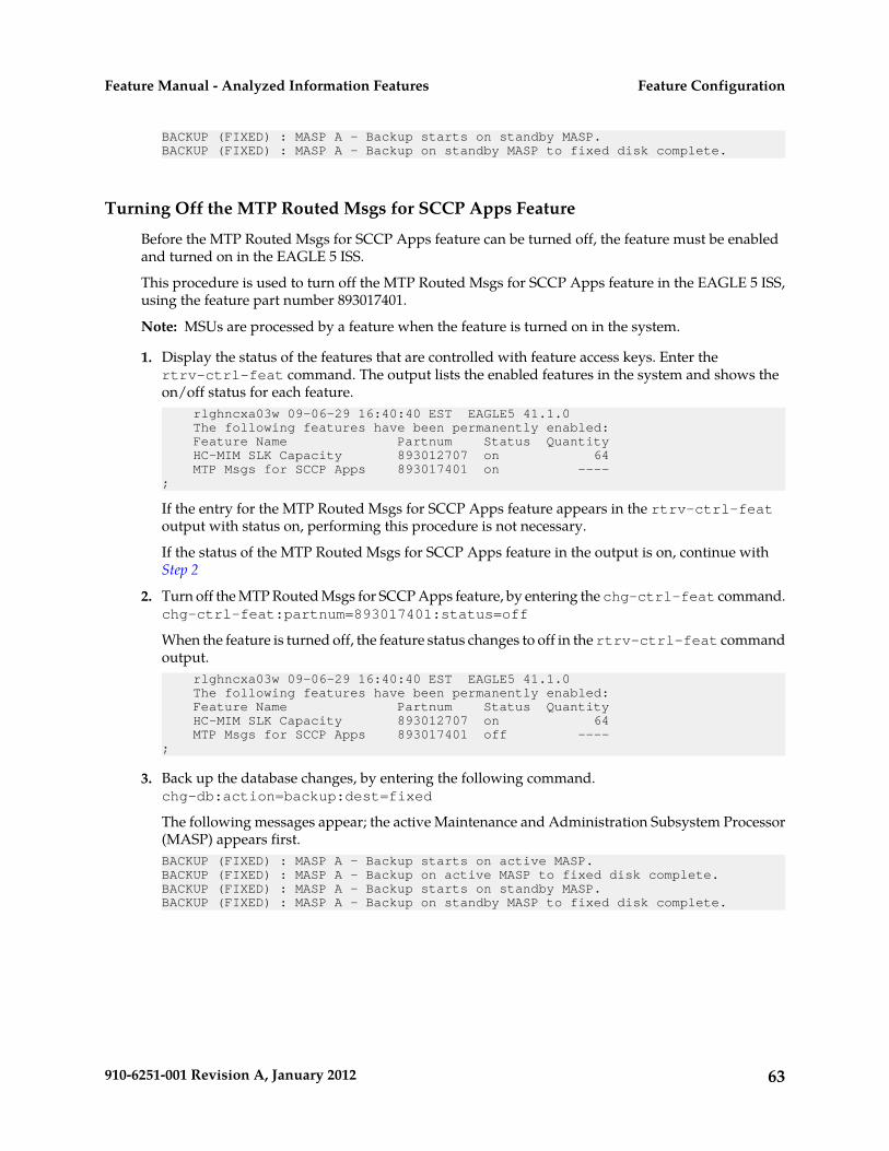
BACKUP (FIXED) : MASP A - Backup starts on standby MASP.BACKUP (FIXED) : MASP A - Backup on standby MASP to fixed disk complete.
Turning Off the MTP Routed Msgs for SCCP Apps Feature
Before the MTP Routed Msgs for SCCP Apps feature can be turned off, the feature must be enabledand turned on in the EAGLE 5 ISS.
This procedure is used to turn off the MTP Routed Msgs for SCCP Apps feature in the EAGLE 5 ISS,using the feature part number 893017401.
Note: MSUs are processed by a feature when the feature is turned on in the system.
1. Display the status of the features that are controlled with feature access keys. Enter thertrv-ctrl-feat command. The output lists the enabled features in the system and shows theon/off status for each feature. rlghncxa03w 09-06-29 16:40:40 EST EAGLE5 41.1.0 The following features have been permanently enabled: Feature Name Partnum Status Quantity HC-MIM SLK Capacity 893012707 on 64 MTP Msgs for SCCP Apps 893017401 on ----;
If the entry for the MTP Routed Msgs for SCCP Apps feature appears in the rtrv-ctrl-featoutput with status on, performing this procedure is not necessary.
If the status of the MTP Routed Msgs for SCCP Apps feature in the output is on, continue withStep 2
2. Turn off the MTP Routed Msgs for SCCP Apps feature, by entering the chg-ctrl-feat command.chg-ctrl-feat:partnum=893017401:status=off
When the feature is turned off, the feature status changes to off in the rtrv-ctrl-feat commandoutput. rlghncxa03w 09-06-29 16:40:40 EST EAGLE5 41.1.0 The following features have been permanently enabled: Feature Name Partnum Status Quantity HC-MIM SLK Capacity 893012707 on 64 MTP Msgs for SCCP Apps 893017401 off ----;
3. Back up the database changes, by entering the following command.chg-db:action=backup:dest=fixed
The following messages appear; the active Maintenance and Administration Subsystem Processor(MASP) appears first.BACKUP (FIXED) : MASP A - Backup starts on active MASP.BACKUP (FIXED) : MASP A - Backup on active MASP to fixed disk complete.BACKUP (FIXED) : MASP A - Backup starts on standby MASP.BACKUP (FIXED) : MASP A - Backup on standby MASP to fixed disk complete.
63910-6251-001 Revision A, January 2012
Feature ConfigurationFeature Manual - Analyzed Information Features

TATR Test Tool
The TATR Test Tool can be used to send provisioned test messages through parts of the IAR Basefeature to test an IAR-related feature configuration before the configuration is used to process realmessage traffic
The TATR Test Tool can be used when the IAR Base feature is enabled and off. The tst-msg commandoperates as though the IAR Base feature is on.
The other IAR-related features can be turned on and off when the IAR Base feature is off. An IAR Baseconfiguration cannot be tested without testing the way in which it uses NPP. The ON/OFF status ofthe IAR NP, IAR ASD, and IAR GRN features influences the processing performed by several NPPService Action Handlers; these handlers will do nothing when the feature that controls them is OFF.
The TATR Test Tool processing is the same as IAR Base processing with the following exceptions:
• TTR service selection is skipped.• IAR pre-NPP processing
• TCAP decoding is replaced by test message data retrieval.• The IAR Base feature supports the tst-msg command in such a way that the same IAR pre-NPP
processing and NPP processing code that is used for run-time message traffic is also exercisedby the test message data.
• If the tst-msg command is used with data that emulates a MTP-routed GTI=0 message, thenthe message will pass IAR pre-NPP processing DPC Screening only when there is at least oneDPC with Home SCP defined in the EAGLE 5 ISS Destination table.
• IAR post-NPP processing message encoding and routing is replaced by TST-MSG output generation.
The following information can be configured for each TATR test message (default values areunderlined.):
Table 17: TATR Test Message Table Fields
DescriptionField
{1..10}
Specifies the number of the test message to be sent for feature service processing;this number identifies the message modified by all of the other parameters.
MSGN
{0, 1, 2, 3 .. 15}
Specifies the CdPA GTI for the message.
CDPAGT
{0, 1, 2, 3, 4, 5 .. 127}
Specifies the CdPA NAI for the message.
CDPAGTNAI
{<s>}, where <s> is a string of between 0 and 15 hexadecimal digits in length, witha default value of 0123456789ABCDE.
Specifies the CdPA GT digits for the message.
CDPADGTS
64910-6251-001 Revision A, January 2012
Feature ConfigurationFeature Manual - Analyzed Information Features

DescriptionField
{0, 1, 2, 3, .., 15}
Specifies the CgPA GTI for the message.
CGPAGT
{0, 1, 2, 3, 4, 5, .., 127}
Specifies the CgPA NAI for the message.
CGPAGTNAI
{<s>}, where <s> is a string of between 0 and 15 hexadecimal digits in length, witha default value of 0123456789ABCDE.
Specifies the CgPA GT digits for the message.
CGPADGTS
{0,1,2,3,.., 255}
Specifies the CgPN NAI for the message.
CDPNNAI
{<s>}, where <s> is a string of between 0 and 32 hexadecimal digits in length, witha default value of 0123456789ABCDE.
Specifies the CdPN GT digits for the message.
CDPNDGTS
{0,1,2,3,.., 255}
Specifies the CgPN NAI for the message.
CGPNNAI
{<s>}, where <s> is a string of between 0 and 32 hexadecimal digits in length, witha default value of 0123456789ABCDE.
Specifies the CgPN GT digits for the message.
CGPNDGTS
{YES, NO}
Specifies whether the message can be sent to the network card for processing.
ACTIVE
{YES}
Resets all of the message parameters to their default values.
RESET
{0..36, 37, 38..255}
Specifies the TRIGTYPE for the message as a hexadecimal number.
TRIGTYPE
The TRIGTYPE may also be entered as a hexadecimal number; range 00..FF, witha default value of 25.
Refer to the "Notes" section of the ent-csl command description in the CommandsManual for a list of hexadecimal codes.
The chg-tatr-msg command is used to configure the parameter values for each TATR test message.The command must specify the message number (one of up to 10 messages) for the message that isbeing configured.
The rtrv-tatr-msg command displays the configured messages in the Test Message table.Configured information for all messages or for one specified message number can be displayed.
The tst-msg command invokes the test. The command must specify the prot=tatr parameter, themessage number for the test, the network card location (loc parameter), the feat=iar parameter, and
65910-6251-001 Revision A, January 2012
Feature ConfigurationFeature Manual - Analyzed Information Features
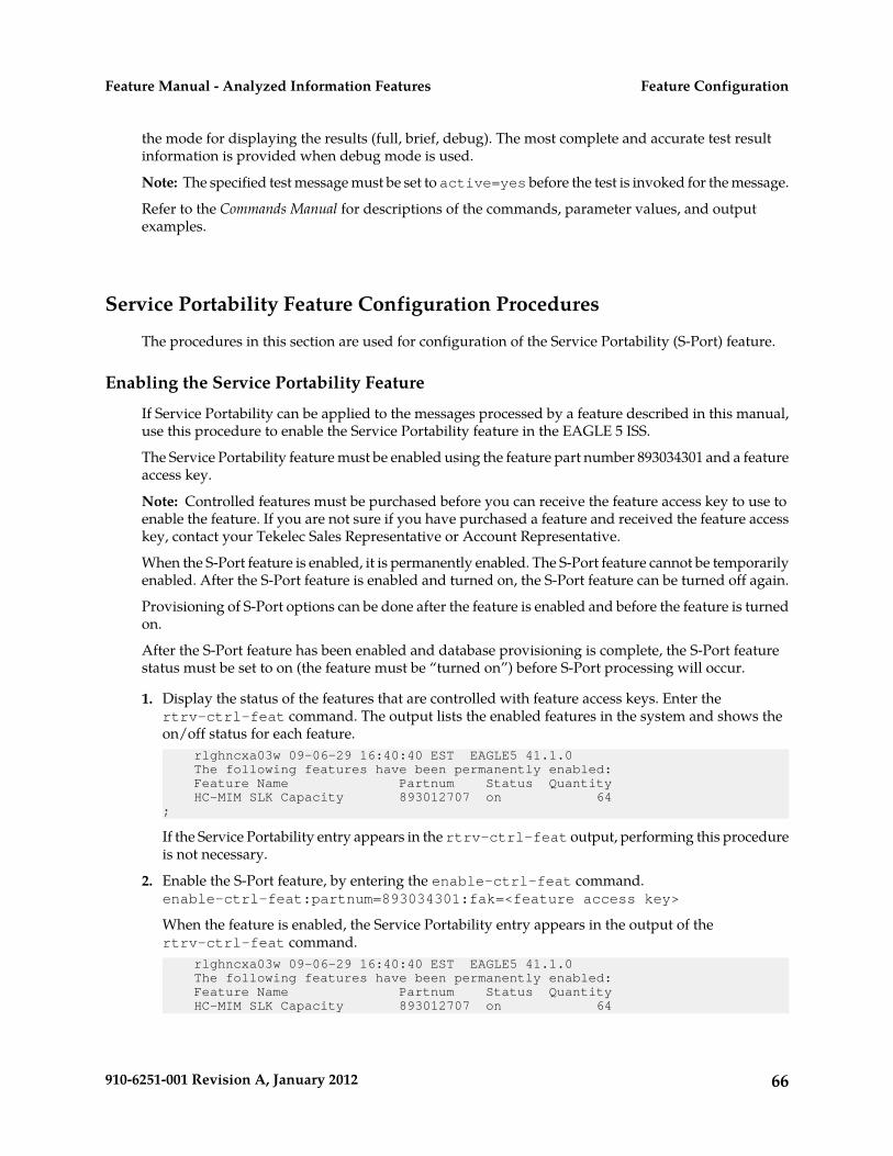
the mode for displaying the results (full, brief, debug). The most complete and accurate test resultinformation is provided when debug mode is used.
Note: The specified test message must be set to active=yes before the test is invoked for the message.
Refer to the Commands Manual for descriptions of the commands, parameter values, and outputexamples.
Service Portability Feature Configuration Procedures
The procedures in this section are used for configuration of the Service Portability (S-Port) feature.
Enabling the Service Portability Feature
If Service Portability can be applied to the messages processed by a feature described in this manual,use this procedure to enable the Service Portability feature in the EAGLE 5 ISS.
The Service Portability feature must be enabled using the feature part number 893034301 and a featureaccess key.
Note: Controlled features must be purchased before you can receive the feature access key to use toenable the feature. If you are not sure if you have purchased a feature and received the feature accesskey, contact your Tekelec Sales Representative or Account Representative.
When the S-Port feature is enabled, it is permanently enabled. The S-Port feature cannot be temporarilyenabled. After the S-Port feature is enabled and turned on, the S-Port feature can be turned off again.
Provisioning of S-Port options can be done after the feature is enabled and before the feature is turnedon.
After the S-Port feature has been enabled and database provisioning is complete, the S-Port featurestatus must be set to on (the feature must be “turned on”) before S-Port processing will occur.
1. Display the status of the features that are controlled with feature access keys. Enter thertrv-ctrl-feat command. The output lists the enabled features in the system and shows theon/off status for each feature. rlghncxa03w 09-06-29 16:40:40 EST EAGLE5 41.1.0 The following features have been permanently enabled: Feature Name Partnum Status Quantity HC-MIM SLK Capacity 893012707 on 64;
If the Service Portability entry appears in the rtrv-ctrl-feat output, performing this procedureis not necessary.
2. Enable the S-Port feature, by entering the enable-ctrl-feat command.enable-ctrl-feat:partnum=893034301:fak=<feature access key>
When the feature is enabled, the Service Portability entry appears in the output of thertrv-ctrl-feat command. rlghncxa03w 09-06-29 16:40:40 EST EAGLE5 41.1.0 The following features have been permanently enabled: Feature Name Partnum Status Quantity HC-MIM SLK Capacity 893012707 on 64
66910-6251-001 Revision A, January 2012
Feature ConfigurationFeature Manual - Analyzed Information Features

Service Portability 893034301 off ---- ;
3. Back up the database changes, by entering the following command.chg-db:action=backup:dest=fixed
The following messages appear; the active Maintenance and Administration Subsystem Processor(MASP) appears first.BACKUP (FIXED) : MASP A - Backup starts on active MASP.BACKUP (FIXED) : MASP A - Backup on active MASP to fixed disk complete.BACKUP (FIXED) : MASP A - Backup starts on standby MASP.BACKUP (FIXED) : MASP A - Backup on standby MASP to fixed disk complete.
Turning On the Service Portability Feature
This procedure is used to turn on the Service Portability feature in the EAGLE 5 ISS, using the featurepart number 893034301.
Before the Service Portability (S-Port) feature can be turned on, the feature must be enabled in theEAGLE 5 ISS.
Provisioning of S-Port options can be done after the feature is enabled and before the feature is turnedon.
After the S-Port feature has been enabled and database provisioning is complete, the Service Portabilityfeature status must be set to on (the feature must be “turned on”). MSUs will not be processed by theService Portability feature until the feature is turned on.
After the Service Portability feature is enabled and turned on, it can be turned off again. ServicePortability processing can occur only when the Service Portability feature is on and a feature that usesS-Port is on.
1. Display the status of the features that are controlled with feature access keys. Enter thertrv-ctrl-feat command. The output lists the enabled features in the system and shows theon/off status for each feature.
• If the entry for the Service Portability feature appears in the rtrv-ctrl-feat output withstatus on, performing this procedure is not necessary.
• If the status of the Service Portability feature in the output is off, continue with Step 2.
2. Turn on the S-Port feature, by entering the chg-ctrl-feat command.chg-ctrl-feat:partnum=893034301:status=on
When the feature is turned on, the feature status changes to on in the rtrv-ctrl-feat commandoutput. rlghncxa03w 09-08-29 16:40:40 EST EAGLE5 41.1.0 The following features have been permanently enabled: Feature Name Partnum Status Quantity HC-MIM SLK Capacity 893012707 on 64 ATINP 893022101 on ---- Service Portability 893034301 on ----;
3. Back up the database changes, by entering the following command.chg-db:action=backup:dest=fixed
67910-6251-001 Revision A, January 2012
Feature ConfigurationFeature Manual - Analyzed Information Features

The following messages appear; the active Maintenance and Administration Subsystem Processor(MASP) appears first.BACKUP (FIXED) : MASP A - Backup starts on active MASP.BACKUP (FIXED) : MASP A - Backup on active MASP to fixed disk complete.BACKUP (FIXED) : MASP A - Backup starts on standby MASP.BACKUP (FIXED) : MASP A - Backup on standby MASP to fixed disk complete.
Turning Off the Service Portability Feature
Before the Service Portability (S-Port) feature can be turned on and off, the feature must be enabledin the EAGLE 5 ISS.
This procedure is used to turn off the Service Portability feature, using its feature part number8930343001.
Note: MSUs will not be processed by a feature when the feature is turned off in the system.
1. Display the status of the features that are controlled with feature access keys. Enter thertrv-ctrl-feat command. The output lists the enabled features in the system and shows theon/off status for each feature. rlghncxa03w 09-06-29 16:40:40 EST EAGLE5 41.1.0 The following features have been permanently enabled: Feature Name Partnum Status Quantity HC-MIM SLK Capacity 893012707 on 64 TIF Number Portability 893018901 on ---- Service Portability 893034301 on ---- ;
If the entry for the Service Portability feature appears in the rtrv-ctrl-feat output with statusoff, performing this procedure is not necessary.
If the status of the Service Portability feature in the output is on, continue with Step 2.
2. Turn off the S-Port feature, by entering the chg-ctrl-feat command.chg-ctrl-feat:partnum=<893034301>:status=off
When the feature is turned off, the feature status changes to off in the rtrv-ctrl-feat commandoutput. rlghncxa03w 09-05-29 16:40:40 EST EAGLE5 41.1.0 The following features have been permanently enabled: Feature Name Partnum Status Quantity HC-MIM SLK Capacity 893012707 on 64 TIF Number Portability 893018901 on ---- Service Portability 893034301 off ----;
3. Back up the database changes, by entering the following command.chg-db:action=backup:dest=fixed
The following messages appear; the active Maintenance and Administration Subsystem Processor(MASP) appears first.BACKUP (FIXED) : MASP A - Backup starts on active MASP.BACKUP (FIXED) : MASP A - Backup on active MASP to fixed disk complete.BACKUP (FIXED) : MASP A - Backup starts on standby MASP.BACKUP (FIXED) : MASP A - Backup on standby MASP to fixed disk complete.
68910-6251-001 Revision A, January 2012
Feature ConfigurationFeature Manual - Analyzed Information Features
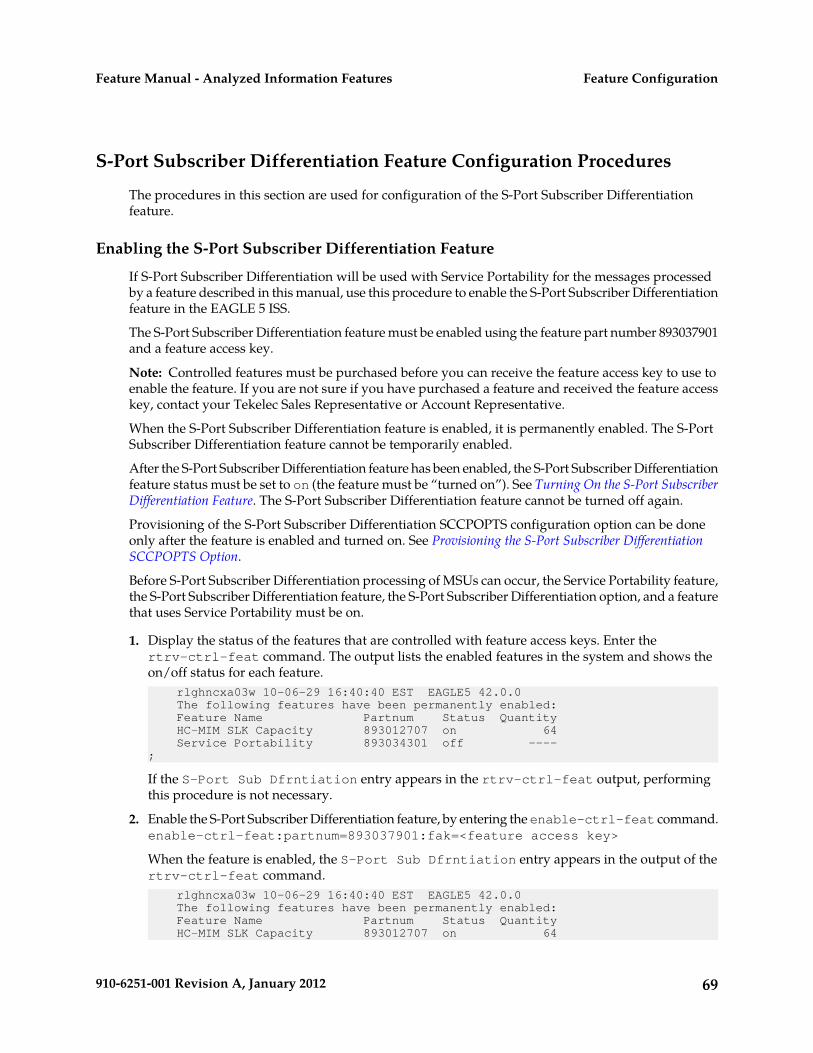
S-Port Subscriber Differentiation Feature Configuration Procedures
The procedures in this section are used for configuration of the S-Port Subscriber Differentiationfeature.
Enabling the S-Port Subscriber Differentiation Feature
If S-Port Subscriber Differentiation will be used with Service Portability for the messages processedby a feature described in this manual, use this procedure to enable the S-Port Subscriber Differentiationfeature in the EAGLE 5 ISS.
The S-Port Subscriber Differentiation feature must be enabled using the feature part number 893037901and a feature access key.
Note: Controlled features must be purchased before you can receive the feature access key to use toenable the feature. If you are not sure if you have purchased a feature and received the feature accesskey, contact your Tekelec Sales Representative or Account Representative.
When the S-Port Subscriber Differentiation feature is enabled, it is permanently enabled. The S-PortSubscriber Differentiation feature cannot be temporarily enabled.
After the S-Port Subscriber Differentiation feature has been enabled, the S-Port Subscriber Differentiationfeature status must be set to on (the feature must be “turned on”). See Turning On the S-Port SubscriberDifferentiation Feature. The S-Port Subscriber Differentiation feature cannot be turned off again.
Provisioning of the S-Port Subscriber Differentiation SCCPOPTS configuration option can be doneonly after the feature is enabled and turned on. See Provisioning the S-Port Subscriber DifferentiationSCCPOPTS Option.
Before S-Port Subscriber Differentiation processing of MSUs can occur, the Service Portability feature,the S-Port Subscriber Differentiation feature, the S-Port Subscriber Differentiation option, and a featurethat uses Service Portability must be on.
1. Display the status of the features that are controlled with feature access keys. Enter thertrv-ctrl-feat command. The output lists the enabled features in the system and shows theon/off status for each feature. rlghncxa03w 10-06-29 16:40:40 EST EAGLE5 42.0.0 The following features have been permanently enabled: Feature Name Partnum Status Quantity HC-MIM SLK Capacity 893012707 on 64 Service Portability 893034301 off ----;
If the S-Port Sub Dfrntiation entry appears in the rtrv-ctrl-feat output, performingthis procedure is not necessary.
2. Enable the S-Port Subscriber Differentiation feature, by entering the enable-ctrl-feat command.enable-ctrl-feat:partnum=893037901:fak=<feature access key>
When the feature is enabled, the S-Port Sub Dfrntiation entry appears in the output of thertrv-ctrl-feat command. rlghncxa03w 10-06-29 16:40:40 EST EAGLE5 42.0.0 The following features have been permanently enabled: Feature Name Partnum Status Quantity HC-MIM SLK Capacity 893012707 on 64
69910-6251-001 Revision A, January 2012
Feature ConfigurationFeature Manual - Analyzed Information Features

Service Portability 893034301 off ---- S-Port Sub Dfrntiation 893037901 off ---- ;
3. Back up the database changes, by entering the following command.chg-db:action=backup:dest=fixed
The following messages appear; the active Maintenance and Administration Subsystem Processor(MASP) appears first.BACKUP (FIXED) : MASP A - Backup starts on active MASP.BACKUP (FIXED) : MASP A - Backup on active MASP to fixed disk complete.BACKUP (FIXED) : MASP A - Backup starts on standby MASP.BACKUP (FIXED) : MASP A - Backup on standby MASP to fixed disk complete.
Turning On the S-Port Subscriber Differentiation Feature
This procedure is used to turn on the S-Port Subscriber Differentiation feature in the EAGLE 5 ISS,using the feature part number 893037901.
Before the S-Port Subscriber Differentiation feature can be turned on, the feature must be enabled inthe EAGLE 5 ISS.
After the S-Port Subscriber Differentiation feature has been enabled, the S-Port Subscriber Differentiationfeature status must be set to on (the feature must be “turned on”). After the S-Port SubscriberDifferentiation feature is enabled and turned on, it cannot be turned off again.
Provisioning of the S-Port Subscriber Differentiation option can be done only after the feature is enabledand turned on. The S-Port Differentiation option can be turned on and off.
MSUs will not be processed by the S-Port Subscriber Differentiation feature until the feature and theoption are turned on. S-Port Subscriber Differentiation processing can occur only when the ServicePortability feature, the S-Port Subscriber Differentiation feature, the S-Port Differentiation option, anda feature that uses Service Portability are all on.
1. Display the status of the features that are controlled with feature access keys. Enter thertrv-ctrl-feat command. The output lists the enabled features in the system and shows theon/off status for each feature.rlghncxa03w 10-06-29 16:40:40 EST EAGLE5 42.0.0 The following features have been permanently enabled: Feature Name Partnum Status Quantity HC-MIM SLK Capacity 893012707 on 64 Info Analyzed Relay Base 893034201 off ---- Service Portability 893034301 off ---- S-Port Sub Dfrntiation 893037901 off ----;
If the S-Port Sub Dfrntiation entry appears in the rtrv-ctrl-feat output with Status ofon, performing this procedure is not necessary.
If the status of the S-Port Subscriber Differentiation feature in the output is off, continue with Step2.
2. Turn on the S-Port Subscriber Differentiation feature, by entering the chg-ctrl-feat command.chg-ctrl-feat:partnum=893037901:status=on
70910-6251-001 Revision A, January 2012
Feature ConfigurationFeature Manual - Analyzed Information Features

When the feature is turned on, the feature status changes to on in the rtrv-ctrl-feat commandoutput. rlghncxa03w 10-08-29 16:40:40 EST EAGLE5 42.0.0 The following features have been permanently enabled: Feature Name Partnum Status Quantity HC-MIM SLK Capacity 893012707 on 64 Info Analyzed Relay Base 893034201 off ---- Service Portability 893034301 off ---- S-Port Sub Dfrntiation 893037901 on ----;
3. Back up the database changes, by entering the following command.chg-db:action=backup:dest=fixed
The following messages appear; the active Maintenance and Administration Subsystem Processor(MASP) appears first.BACKUP (FIXED) : MASP A - Backup starts on active MASP.BACKUP (FIXED) : MASP A - Backup on active MASP to fixed disk complete.BACKUP (FIXED) : MASP A - Backup starts on standby MASP.BACKUP (FIXED) : MASP A - Backup on standby MASP to fixed disk complete.
Provisioning the S-Port Subscriber Differentiation SCCPOPTS Option
This procedure is used to provision the SCCPOPTS configuration option for the S-Port SubscriberDifferentiation feature.
The S-Port Subscriber Differentiation feature must be enabled and turned on before SCCPOPTSSUBDFRN option can be provisioned.
1. Verify that the S-Port Subscriber Differentiation feature is enabled and on, by entering thertrv-ctrl-feat command. rlghncxa03w 10-06-29 16:40:40 EST EAGLE5 42.0.0 The following features have been permanently enabled: Feature Name Partnum Status Quantity HC-MIM SLK Capacity 893012707 on 64 Info Analyzed Relay Base 893034201 off ---- Service Portability 893034301 off ---- S-Port Sub Dfrntiation 893037901 on ----;
• If the S-Port Sub Dfrntiation feature is enabled and turned on, continue with Step 2.• If the S-Port Sub Dfrntiation entry does not appear in the output, go to Enabling the S-Port
Subscriber Differentiation Feature and Turning On the S-Port Subscriber Differentiation Feature toenable and turn on the feature. Then continue with Step 2.
• If the feature is enabled but not turned on (the entry shows Status off), go to Turning On theS-Port Subscriber Differentiation Featureto turn on the feature. Then continue with Step 2.
2. Display the current settings of the SCCPOPTS options, using the rtrv-sccpopts command.3. Change the SCCPOPTS SUBDFRN option to the required setting (on or off), by entering the
chg-sccpopts command with the subdfrn option parameter specified.Refer to the chg-sccpopts command description in the Commands Manual for valid parametervalues, input examples, and rules for entering the command correctly.
4. Verify the changes, by entering the rtrv-sccpopts command.5. Back up the changes, using the chg-db:action=backup:dest=fixed command.
71910-6251-001 Revision A, January 2012
Feature ConfigurationFeature Manual - Analyzed Information Features
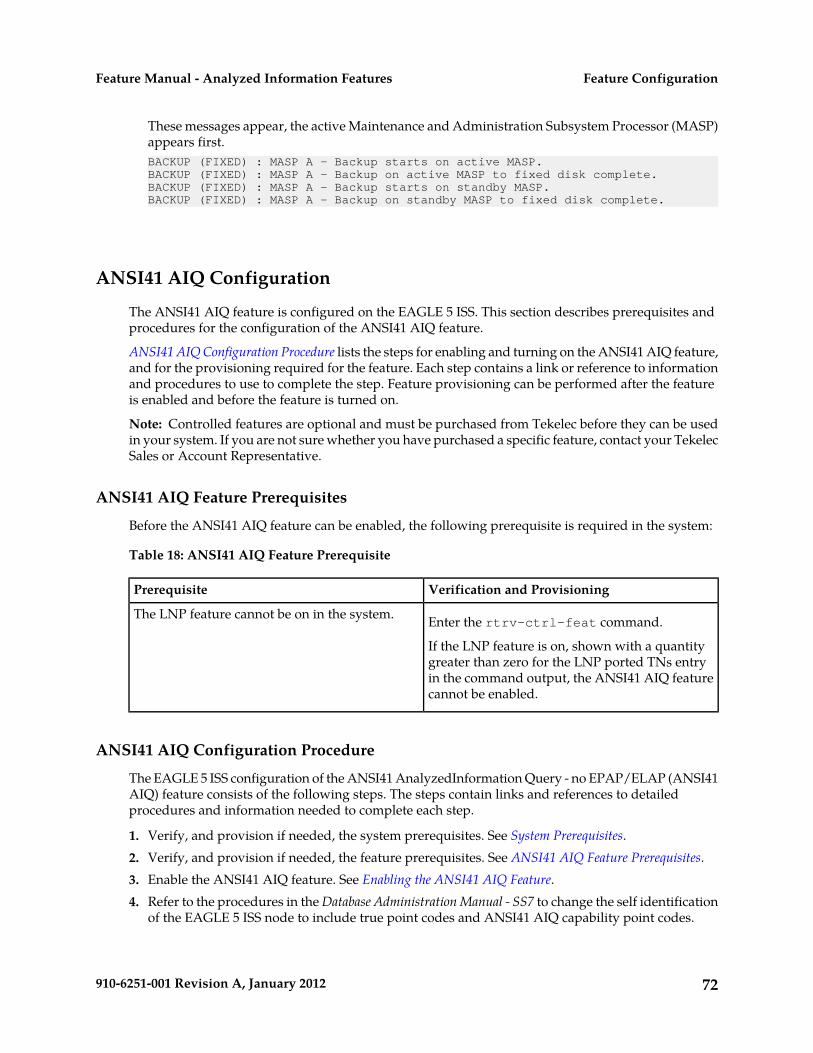
These messages appear, the active Maintenance and Administration Subsystem Processor (MASP)appears first.BACKUP (FIXED) : MASP A - Backup starts on active MASP.BACKUP (FIXED) : MASP A - Backup on active MASP to fixed disk complete.BACKUP (FIXED) : MASP A - Backup starts on standby MASP.BACKUP (FIXED) : MASP A - Backup on standby MASP to fixed disk complete.
ANSI41 AIQ Configuration
The ANSI41 AIQ feature is configured on the EAGLE 5 ISS. This section describes prerequisites andprocedures for the configuration of the ANSI41 AIQ feature.
ANSI41 AIQ Configuration Procedure lists the steps for enabling and turning on the ANSI41 AIQ feature,and for the provisioning required for the feature. Each step contains a link or reference to informationand procedures to use to complete the step. Feature provisioning can be performed after the featureis enabled and before the feature is turned on.
Note: Controlled features are optional and must be purchased from Tekelec before they can be usedin your system. If you are not sure whether you have purchased a specific feature, contact your TekelecSales or Account Representative.
ANSI41 AIQ Feature Prerequisites
Before the ANSI41 AIQ feature can be enabled, the following prerequisite is required in the system:
Table 18: ANSI41 AIQ Feature Prerequisite
Verification and ProvisioningPrerequisite
Enter the rtrv-ctrl-feat command.The LNP feature cannot be on in the system.
If the LNP feature is on, shown with a quantitygreater than zero for the LNP ported TNs entryin the command output, the ANSI41 AIQ featurecannot be enabled.
ANSI41 AIQ Configuration Procedure
The EAGLE 5 ISS configuration of the ANSI41 AnalyzedInformation Query - no EPAP/ELAP (ANSI41AIQ) feature consists of the following steps. The steps contain links and references to detailedprocedures and information needed to complete each step.
1. Verify, and provision if needed, the system prerequisites. See System Prerequisites.2. Verify, and provision if needed, the feature prerequisites. See ANSI41 AIQ Feature Prerequisites.3. Enable the ANSI41 AIQ feature. See Enabling the ANSI41 AIQ Feature.4. Refer to the procedures in the Database Administration Manual - SS7 to change the self identification
of the EAGLE 5 ISS node to include true point codes and ANSI41 AIQ capability point codes.
72910-6251-001 Revision A, January 2012
Feature ConfigurationFeature Manual - Analyzed Information Features

5. Refer to the procedures in the Database Administration Manual - Global Title Translation to provisionthe following items:
• Translation types and mappings• Mated Application (MAP) table entries for the ANSI41 AIQ feature that contain the EAGLE 5
ISS true point codes, the ANSI41 AIQ capability point codes, and the ANSI41 AIQ subsystemnumber. Only solitary and dominant loadsharing are supported.
The AIQ local subsystem can have a mate subsystem and a concerned point code group assignedto it in the MAP table.
If multiple point code types for ANSI41 AIQ are provisioned in the MAP table, then the point codetype for the Subsystem Out-of-Service Request message (SOR) is determined using the followingorder:
• ANSI• ITU-N• ITU-N Spare• ITU-I• ITU-I Spare
6. Provision the state and subsystem number for the AIQ local subsystem application. See Provisioningthe AIQ Local Subsystem.
7. Provision the service selector for the ANSI41 AIQ feature (aiq). See Provisioning the AIQ ServiceSelector.
8. Provision ANSI41 AIQ (AIQOPTS) options. See Provisioning the ANSI41 AIQ Options.
• Minimum and maximum length for Digits (Dialed), Trigger Type Prefix or Prefix and IncomingDigits (Dialed) response format, and RoutingDigits or Digits (Dialed) Return Result parameter.
• Trigger Type and Prefix pairs• TCAP Error Code
9. Turn on the ANSI41 AIQ feature. See Turning On the ANSI41 AIQ Feature.10. Activate the AIQ local subsystem. See Activating the AIQ Local Subsystem.
Enabling the ANSI41 AIQ Feature
This procedure is used to enable the ANSI41 AIQ feature in the EAGLE 5 ISS.
• The ANSI41 AIQ feature must be enabled using the ANSI41 AIQ feature part number 893034901and a feature access key.
Note: Controlled features must be purchased before you can receive the feature access key to useto enable the feature. If you are not sure if you have purchased a feature and received the featureaccess key, contact your Tekelec Sales Representative or Account Representative.
When the ANSI41 AIQ feature is enabled, it is permanently enabled. The ANSI41 AIQ featurecannot be temporarily enabled.Provisioning of ANSI41 AIQ options and other information can be done after the feature is enabledand before the feature is turned on.
73910-6251-001 Revision A, January 2012
Feature ConfigurationFeature Manual - Analyzed Information Features

• After the ANSI41 AIQ feature has been enabled and database provisioning is complete, the ANSI41AIQ feature status must be set to on (the feature must be “turned on”) to begin operation in thesystem. See Turning On the ANSI41 AIQ Feature.
After the ANSI41 AIQ feature is enabled and turned on, the ANSI41 AIQ feature can be turned offagain.
1. Enable the ANSI41 AIQ feature, by entering the enable-ctrl-feat command.enable-ctrl-feat:partnum=893034901:fak=<feature access key>
2. Verify that the ANSI41 AIQ feature is enabled. Enter the rtrv-ctrl-feat command.
When the feature is enabled, the ANSI41 AIQ entry appears in the output of the rtrv-ctrl-featcommand. rlghncxa03w 08-08-29 16:40:40 EST EAGLE5 42.0.0 The following features have been permanently enabled: Feature Name Partnum Status Quantity HC-MIM SLK Capacity 893012707 on 64 ANSI41 AIQ 893034901 off ----;
3. Back up the database changes, by entering the following command.chg-db:action=backup:dest=fixed
The following messages appear; the active Maintenance and Administration Subsystem Processor(MASP) appears first.BACKUP (FIXED) : MASP A - Backup starts on active MASP.BACKUP (FIXED) : MASP A - Backup on active MASP to fixed disk complete.BACKUP (FIXED) : MASP A - Backup starts on standby MASP.BACKUP (FIXED) : MASP A - Backup on standby MASP to fixed disk complete.
Provisioning the AIQ Local Subsystem
The following procedures in this section are used to add or remove a local subsystem application:
• Adding the AIQ Local Subsystem Application• Removing a Local Subsystem Application
See the procedures in Changing the State of a Subsystem Application to take the subsystem applicationonline or offline.
Adding the AIQ Local Subsystem ApplicationThis procedure is used to define the AIQ subsystem application. The subsystem application can betaken online when it is defined or later in the configuration process (see Changing the State of a SubsystemApplication).
Before the AIQ subsystem application can be added to the database, the following conditions mustexist in the system:
74910-6251-001 Revision A, January 2012
Feature ConfigurationFeature Manual - Analyzed Information Features

Table 19: AIQ Local Subsystem Prerequisites
VerificationPrerequisite
Enter the rtrv-ctrl-feat command.The ANSI41 AIQ feature must be enabled andturned on
If the ANSI41 AIQ entry with Status of on doesnot appear in the output, see the Enabling theANSI41 AIQ Feature and Turning On the ANSI41AIQ Feature procedures.
Enter the rtrv-ss-appl command.The application specified by the appl parameter(aiq) cannot already be in the database.
If the AIQ entry appears in the output, thisprocedure cannot be performed.
Only one subsystem number for the applicationcan be defined, and must be used for all pointcode types assigned to the local subsystem.
EAGLE 5 ISS true point codes and AIQ capabilitypoint codes must be defined, and entered in theMated Application table with a subsystem numberto be used for the AIQ subsystem application.
Enter the rtrv-sid command, and verify thatthe true and capability point codes needed for thefeature are correct. If changes are required, referto the procedures in the Database AdministrationManual - SS7.
Enter the rtrv-map command, and verify thatthe MAP table entries are correct for the AIQ localsubsystem. If changes are required, refer to theprocedures in the Database Administration Manual– Global Title Translation for provisioning solitaryand dominant mated applications.
The examples in this procedure reserve the subsystem number 100 for the AIQ subsystem applicationand set the AIQ subsystem application status to online.
1. Add the AIQ application and subsystem number, using the ent-ss-appl command.
If the stat parameter is not specified, the status defaults to offline.ent-ss-appl:appl=aiq:ssn=100:stat=online
2. Verify the changes, by entering the rtrv-ss-appl command. tekelecstp 10-04-25 08:02:22 EST EAGLE 42.0.0 APPL SSN STAT AIQ 100 online
SS-APPL TABLE IS 25% FULL (1 OF 4);
3. Back up the changes using the chg-db:action=backup:dest=fixed command. The following messagesappear, the active Maintenance and Administration Subsystem Processor (MASP) appears first.BACKUP (FIXED): MASP A - Backup starts on active MASP.BACKUP (FIXED): MASP A - Backup on active MASP to fixed disk complete.BACKUP (FIXED): MASP A - Backup starts on standby MASP.BACKUP (FIXED): MASP A - Backup on standby MASP to fixed disk complete.
75910-6251-001 Revision A, January 2012
Feature ConfigurationFeature Manual - Analyzed Information Features
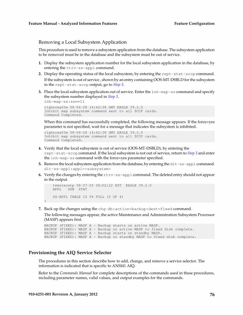
Removing a Local Subsystem ApplicationThis procedure is used to remove a subsystem application from the database. The subsystem applicationto be removed must be in the database and the subsystem must be out of service.
1. Display the subsystem application number for the local subsystem application in the database, byentering the rtrv-ss-appl command.
2. Display the operating status of the local subsystem, by entering the rept-stat-sccp command.If the subsystem is out of service , shown by an entry containing OOS-MT-DSBLD for the subsystemin the rept-stat-sccp output, go to Step 5.
3. Place the local subsystem application out of service. Enter the inh-map-ss command and specifythe subsystem number displayed in Step 1.inh-map-ss:ssn=11
rlghncxa03w 08-06-28 14:42:38 GMT EAGLE 39.2.0Inhibit map subsystem command sent to all SCCP cards.Command Completed.
When this command has successfully completed, the following message appears. If the force=yesparameter is not specified, wait for a message that indicates the subsystem is inhibited.rlghncxa03w 08-06-28 14:42:38 GMT EAGLE 39.2.0Inhibit map subsystem command sent to all SCCP cards.Command Completed.
4. Verify that the local subsystem is out of service (OOS-MT-DSBLD), by entering therept-stat-sccp command. If the local subsystem is not out of service, return to Step 3 and enterthe inh-map-ss command with the force=yes parameter specified.
5. Remove the local subsystem application from the database, by entering the dlt-ss-appl command.dlt-ss-appl:appl=<subsystem>
6. Verify the changes by entering the rtrv-ss-appl command. The deleted entry should not appearin the output. tekelecstp 08-07-25 08:02:22 EST EAGLE 39.2.0 APPL SSN STAT
SS-APPL TABLE IS 0% FULL (0 OF 4);
7. Back up the changes using the chg-db:action=backup:dest=fixed command.The following messages appear, the active Maintenance and Administration Subsystem Processor(MASP) appears first.BACKUP (FIXED): MASP A - Backup starts on active MASP.BACKUP (FIXED): MASP A - Backup on active MASP to fixed disk complete.BACKUP (FIXED): MASP A - Backup starts on standby MASP.BACKUP (FIXED): MASP A - Backup on standby MASP to fixed disk complete.
Provisioning the AIQ Service Selector
The procedures in this section describe how to add, change, and remove a service selector. Theinformation is indicated that is specific to ANSI41 AIQ.
Refer to the Commands Manual for complete descriptions of the commands used in these procedures,including parameter names, valid values, and output examples for the commands.
76910-6251-001 Revision A, January 2012
Feature ConfigurationFeature Manual - Analyzed Information Features

Adding an AIQ Service SelectorThis procedure is used to add a service selector for the ANSI41 AIQ feature.
The ANSI41 AIQ feature must be enabled before an AIQ service selector can be added.
1. Verify that the ANSI41 AIQ feature is enabled, by entering the rtrv-ctrl-feat command.
If the ANSI41 AIQ feature is enabled, the ANSI41 AIQ entry appears in the output. rlghncxa03w 09-06-29 16:40:40 EST EAGLE5 41.1.0 The following features have been permanently enabled: Feature Name Partnum Status Quantity HC-MIM SLK Capacity 893012707 on 64 ANSI41 AIQ 893034901 off ---- ;
• If the ANSI41 AIQ feature is enabled, continue with Step 2.• If the ANSI41 AIQ feature is not enabled (does not appear in the output), go to Enabling the
ANSI41 AIQ Featureto enable the feature. Then continue with Step 2.
2. Display any existing AIQ service selectors in the database, by entering the rtrv-srvsel:serv=aiqcommand. rlghncxa03w 08-06-28 14:42:38 GMT EAGLE 41.1.0
GTII TT NP NAI SSN SNP SNAI SERV
4 1 e164 intl 3 --- --- aiq 4 2 e164 intl * --- --- aiq
GTIN TT NP NAI SSN SNP SNAI SERV
4 4 e164 natl 4 --- --- aiq
SRV SELECTOR table is (3 of 20992) 1 % full ;
3. Add new AIQ service selectors, using the ent-srvsel command. For example, enter commandslike these:
ent-srvsel:serv=aiq:tt=35:ssn=100:gtin=4:np=e214:nai=natl
ent-srvsel:serv=aiq:tt=57:ssn=75:gtin=2
4. Verify the changes by entering the rtrv-srvsel command with the parameters and values usedin Step 3. rlghncxa03w 08-06-28 14:42:38 GMT EAGLE 41.1.0
GTII TT NP NAI SSN SNP SNAI SERV
4 1 e164 intl 3 --- --- aiq 4 2 e164 intl * --- --- aiq
GTIN TT NP NAI SSN SNP SNAI SERV
4 4 e164 natl 4 --- --- aiq 4 35 e214 natl 100 --- --- aiq 2 57 --- --- 75 --- --- aiq
77910-6251-001 Revision A, January 2012
Feature ConfigurationFeature Manual - Analyzed Information Features
SRV SELECTOR table is (5 of 20992) 1 % full ;
5. Back up the changes using the chg-db:action=backup:dest=fixed command.The following messages appear, the active Maintenance and Administration Subsystem Processor(MASP) appears first.BACKUP (FIXED): MASP A - Backup starts on active MASP.BACKUP (FIXED): MASP A - Backup on active MASP to fixed disk complete.BACKUP (FIXED): MASP A - Backup starts on standby MASP.BACKUP (FIXED): MASP A - Backup on standby MASP to fixed disk complete.
Removing a Service SelectorThis procedure is used to remove a service selector from the database.
1. Display the service selectors in the database, by entering the rtrv-srvsel command.
The serv, gtii, gtin, tt, and ssn parameter values can be used to limit the amount of informationdisplayed with the rtrv-srvsel command.
2. Remove the service selector from the database, using the dlt-srvsel command. .
For example, enter a commands like these
dlt-srvsel:serv=aiq:tt=35:ssn=100:gtin=4:np=e214:nai=natl
dlt-srvsel:serv=aiq:tt=57:ssn=75:gtin=2
To remove a service selector, the gtii, gtin, tt, and ssn parameter values must be entered as shownin the rtrv-srvsel command output.
3. Verify the changes by entering the rtrv-srvsel command with the parameters and values usedin Step 2.
rtrv-srvsel:serv=aiq:tt=35:ssn=100:gtin=4:np=e214:nai=natl
rlghncxa03w 08-06-28 14:42:38 GMT EAGLE 39.2.0
GTIN TT NP NAI SSN SNP SNAI SERV
No SRV Selector found in range
;
rtrv-srvsel:serv=aiq:tt=57:ssn=75:gtin=2
tekelecstp 08-08-28 16:35:22 EST EAGLE 39.2.0 GTII TT NP NAI NPV NAIV SSN SNP SNAI SERV No SRV Selector found in range
;
4. Back up the changes using the chg-db:action=backup:dest=fixed command.
78910-6251-001 Revision A, January 2012
Feature ConfigurationFeature Manual - Analyzed Information Features

The following messages appear, the active Maintenance and Administration Subsystem Processor(MASP) appears first.BACKUP (FIXED): MASP A - Backup starts on active MASP.BACKUP (FIXED): MASP A - Backup on active MASP to fixed disk complete.BACKUP (FIXED): MASP A - Backup starts on standby MASP.BACKUP (FIXED): MASP A - Backup on standby MASP to fixed disk complete.
Changing an Existing Service Selector to an ANSI41 AIQ Service SelectorThis procedure is used to change an existing non-AIQ service selector to an AIQ service selector.
The only parameters that can be changed using this procedure are:
The chg-srvsel command requires that the gtii/gtin, tt, ssn, and serv parameters be specified withthe values shown in the rtrv-srvsel output for the service selector that is being changed. If any ofthese parameter values need to be changed for an AIQ service selector, use the procedure in Removinga Service Selector to remove the existing service selector. Then use the procedure in Adding an AIQService Selector to add the new AIQ service selector with the new parameter information.
1. Display the service selectors in the database, using the rtrv-srvsel command. rlghncxa03w 10-04-28 14:42:38 GMT EAGLE 42.0.0
GTII TT NP NAI SSN SNP SNAI SERV
4 1 e214 intl 4 e164 intl gport
4 1 e214 intl 5 e164 intl smsmr
4 2 e214 intl 5 e164 intl mnpsms
4 2 e164 intl * --- --- vflex
GTIN TT NP NAI SSN SNP SNAI SERV
4 4 e214 natl 34 e164 intl gflex
4 9 e214 natl --- e164 intl gflex
SRV SELECTOR table is (6 of 20992) 1 % full
;
• If the rtrv-srvseloutput does not show any AIQ service selectors, continue with Step 2.• If the rtrv-srvseloutput shows at least one AIQ service selector, go to Step 3.
2. Verify that the ANSI41 AIQ feature is enabled, by entering the rtrv-ctrl-feat command. Ifthe ANSI41 AIQ feature is enabled, the ANSI41 AIQ entry appears in the output.
• If the ANSI41 AIQ feature is enabled, continue with Step 3.• If the ANSI41 AIQ feature is not enabled (does not appear in the output), go to Enabling the
ANSI41 AIQ Feature to enable the feature. Then continue with Step 3.
79910-6251-001 Revision A, January 2012
Feature ConfigurationFeature Manual - Analyzed Information Features
3. Change the service selector, using a chg-srvsel command similar to the following example.
For example, enter a command like the following one:chg-srvsel:gtin=4:tt=4:np=e214:nai=natl:ssn=34:nsnp=none:nsnai=none:nserv=aiq
If the SNP, or SNAI parameter values are shown as dashes in the rtrv-srvsel output, theseparameters cannot be specified with the chg-srvsel command. If the gtii/gtin/gtin24 parametervalue is 2, the np, nai, npv, and naiv parameters cannot be specified with the chg-srvselcommand.
If the gtii/gtin parameter value is 4, either the np and nai, or the npv and naiv parameters mustbe specified with the chg-srvselcommand. The np and nai parameters can be specified in placeof the npv and naiv parameters, and the npv and naiv parameters can be specified in place of thenp and naiv parameters as long as parameter values be specified correspond to the values shownin the rtrv-srvseloutput. Refer to the chg-srvsel command description in the CommandsManual.
4. Verify the changes by entering the rtrv-srvsel command with the serv=aiq parameter and thevalues for the other parameter that were used in Step 3.
5. Back up the changes using the chg-db:action=backup:dest=fixed command.
The following messages appear, the active Maintenance and Administration Subsystem Processor(MASP) appears first.BACKUP (FIXED): MASP A - Backup starts on active MASP.BACKUP (FIXED): MASP A - Backup on active MASP to fixed disk complete.BACKUP (FIXED): MASP A - Backup starts on standby MASP.BACKUP (FIXED): MASP A - Backup on standby MASP to fixed disk complete.
Provisioning the ANSI41 AIQ Options
Refer to EAGLE 5 ISS Commands in this manual and to the chg-aiqopts command description inthe Commands Manual for valid parameter values, input examples, and rules for entering the commandcorrectly.
1. Verify that the ANSI41 AIQ feature is enabled, by entering the rtrv-ctrl-feat command.
If the ANSI41 AIQ feature has not been turned on, the Status in the ANSI41 AIQ entry is off. rlghncxa03w 10-04-29 16:40:40 EST EAGLE5 42.0.0 The following features have been permanently enabled: Feature Name Partnum Status Quantity HC-MIM SLK Capacity 893012707 on 64 ANSI41 AIQ 893034901 off ----;
• If the ANSI41 AIQ feature is enabled, continue with Step 2.• If the ANSI41 AIQ feature is not enabled (the ANSI41 AIQ entry does not appear in the output),
go to Enabling the ANSI41 AIQ Feature to enable the ANSI41 AIQ feature. Then continue withStep 2.
2. Display the current settings of the ANSI41 AIQ options, using the rtrv-aiqopts command.3. Change the ANSI41 AIQ options to the required settings, by entering the chg-aiqopts command
with at least one of the ANSI41 AIQ option parameters specified.
chg-aiqopts:digminlen=<Min Digit Len>:digmaxlen=<Max Digit Len>:resfmt=<prxor prxd>:respar=<RoutingDigits or DialedDigits>
80910-6251-001 Revision A, January 2012
Feature ConfigurationFeature Manual - Analyzed Information Features

4. Verify the changes, by entering the rtrv-aiqopts command.5. If the ANSI41 AIQ feature was not turned on (feature Status is off in the output in Step 1), go to
Turning On the ANSI41 AIQ Feature to turn on the feature.6. Back up the changes, using the chg-db:action=backup:dest=fixed command.
These messages appear, the active Maintenance and Administration Subsystem Processor (MASP)appears first.BACKUP (FIXED) : MASP A - Backup starts on active MASP.BACKUP (FIXED) : MASP A - Backup on active MASP to fixed disk complete.BACKUP (FIXED) : MASP A - Backup starts on standby MASP.BACKUP (FIXED) : MASP A - Backup on standby MASP to fixed disk complete.
Turning On the ANSI41 AIQ Feature
After the ANSI41 AIQ feature has been enabled and database provisioning is complete, the ANSI41AIQ feature status must be set to on (the feature must be “turned on”).
This procedure is used to turn on the ANSI41 AIQ feature in the EAGLE 5 ISS.
1. Verify that the ANSI41 AIQ feature is enabled in the system. Enter the rtrv-ctrl-feat command.
When the feature is enabled, the ANSI41 AIQ entry appears in the output of the rtrv-ctrl-featcommand. rlghncxa03w 08-08-29 16:40:40 EST EAGLE5 42.0.0 The following features have been permanently enabled: Feature Name Partnum Status Quantity HC-MIM SLK Capacity 893012707 on 64 ANSI41 AIQ 893034901 off ----;
• If the ANSI41 AIQ feature is enabled and not turned on (the feature appears in the output withStatus of off), continue with Step 2.
• If the ANSI41 AIQ feature is enabled and turned on (the feature appears in the output withStatus of on), this procedure is not necessary.
• If the ANSI41 AIQ feature is not enabled (the feature does not appear in the output), go to toenable the feature. Then continue with Step 2.
2. Turn on the ANSI41 AIQ feature. Enter the chg-ctrl-feat command.
chg-ctrl-feat:partnum=893034901:status=on
3. Verify that the feature is turned on. Enter the rtrv-ctrl-feat command.
When the feature is turned on, the status changes to on in the rtrv-ctrl-feat command output. rlghncxa03w 09-06-29 16:40:40 EST EAGLE5 42.0.0 The following features have been permanently enabled: Feature Name Partnum Status Quantity HC-MIM SLK Capacity 893012707 on 64 ANSI41 AIQ 893034901 on ----;
4. Back up the database changes, by entering the chg-db:action=backup:dest=fixed command.
81910-6251-001 Revision A, January 2012
Feature ConfigurationFeature Manual - Analyzed Information Features

The following messages appear; the active Maintenance and Administration Subsystem Processor(MASP) appears first.BACKUP (FIXED) : MASP A - Backup starts on active MASP.BACKUP (FIXED) : MASP A - Backup on active MASP to fixed disk complete.BACKUP (FIXED) : MASP A - Backup starts on standby MASP.BACKUP (FIXED) : MASP A - Backup on standby MASP to fixed disk complete.
Changing the State of a Subsystem Application
The procedures in this section are used to set the state of an existing subsystem application to eitheronline or offline.
The online or offline status of the subsystem application is shown in the STAT field of thertrv-ss-appl command output.
The rept-stat-sccp command displays the operating state (in or out of service) of the subsystem.
If the subsystem application is to be taken online, the subsystem application must be offline.
When the subsystem is taken online (regardless of how the subsystem was taken offline), the EAGLE5 ISS sends SNR/SSA. A UAM is generated, indicating that the subsystem is ALLOWED.
If the subsystem application is to be taken offline, the subsystem application must be online. Thesubsystem must be taken out of service (OOS-MT-DSBLD) with the inh-map-ss command beforeit can be taken offline.
A subsystem application can be taken offline using coordinated state change, or forced offline withoutusing coordinated state change.
When the inh-map-ss command is entered for the subsystem, a coordinated shutdown is attempted.If the coordinated shutdown fails, a UIM is generated, indicating that the shutdown failed. If the forceparameter is specified, the subsystem is forced to shut down; a coordinated shutdown is not performed.
For coordinated state change, SCMG sends an SOR message to the mated subsystem and will start aTcoord timer (30 seconds). If SCMG receives an SOG message from the mated subsystem before theTcoord timer expires, SCMG will broadcast SSPs to the concerned point code group, send SBR/SSP,and take the subsystem offline. A UAM is generated, indicating that the subsystem is PROHIBITED.If the SOG is not received before Tcoord expires, then the inhibit request is denied and a UIM is generated.
When the subsystem is taken offline without coordinated state change, the EAGLE 5 ISS sendsSBR/SSPs. A UAM is generated, indicating that the subsystem is PROHIBITED.
When the EAGLE 5 ISS receives an SOR message from its mated subsystem, it will reply with an SOGmessage if both of the following conditions are met:
• The local subsystem is available• The total load on the DSM subsystem is less than 45% of its capacity
If either of these conditions is not met, the EAGLE 5 ISS will not reply to the SOR message.
Activating the AIQ Local Subsystem
The procedure in this section explains how to activate the AIQ local subsystem.
When all feature configuration is complete, the AIQ subsystem application must taken online and thelocal subsystem must be activated to allow it to begin operation.
82910-6251-001 Revision A, January 2012
Feature ConfigurationFeature Manual - Analyzed Information Features

When the local subsystem operating state is Inhibited, the chg-ss-appl command can be used tochange the online or offline database state of the subsystem. The rtrv-ss-appl command displaysthe online or offline provisioned value.
When the first Service Module card is loaded, this state tells whether the subsystem should beconsidered allowed (online) or inhibited (offline). This is a database state. If the command is accepted,then the change is made to the tables and can be read after an init-sys command is entered toinitialize the system.
When the Service Module cards are in-service and the subsystem application is online, thealw/inh-map-ss commands can be used to change the dynamic operating state of the local subsystemto allowed or inhibited. The inh-map-ss command does not necessarily force a state change, becauseit can fail if the mate does not send an SOG. The force=yes parameter must be specified to bypass theSOR/SOG exchange and inhibit immediately. (There is no rtrv-map-ss command.)
The procedures in Changing the State of a Subsystem Application explain how to take a local subsystemonline and offline.
Table 20: Subsystem Allow/Inhibit
OnlineOfflineCommand\ Subsystem State
Attempts to make the localsubsystem active.
Command is rejectedbecause the subsystemmust be online to be in theAllowed state.
alw-map-ss
Attempts to inhibit thelocal subsystem. Use of the
Command accepted, but noaction because offlineimplies inhibited.
inh-map-ss
force=yes parameterbypasses the SOR/SOGexchange and inhibitsimmediately.
No change to localsubsystem status in thedatabase.
Changes local subsystemstatus to online.
chg-ss-appl:appl=aiq:nstat=online
Changes local subsystemdatabase status to offline.
Command is rejectedbecause the subsystemmust be inhibited to gooffline.
chg-ss-appl:appl=aiq:nstat=offline
1. Display the online/offline status of the AIQ subsystem application, by entering the rtrv-ss-applcommand. tekelecstp 10-04-25 08:02:22 EST EAGLE 42.0.0 APPL SSN STAT AIQ 11 offline
SS-APPL TABLE IS 25% FULL (1 OF 4);
2. Change the AIQ subsystem status to online.chg-ss-appl:appl=aiq:nstat=online
3. Enter the command to allow the AIQ subsystem to begin operation.
83910-6251-001 Revision A, January 2012
Feature ConfigurationFeature Manual - Analyzed Information Features

alw-map-ss:ssn=<AIQ ssn>
integrat40 10-04-24 10:37:22 EST EAGLE5 42.0.0 Allow map subsystem command sent to all SCCP cards. Command Completed.;
4. Display the operating status of the AIQ subsystem, by entering the rept-stat-sccp command.
Turning Off the ANSI41 AIQ Feature
This procedure is used to turn off the ANSI41 AIQ feature in the EAGLE 5 ISS.
1. Verify that the ANSI41 AIQ feature is enabled and turned on in the system. Enter thertrv-ctrl-feat command.
When the feature is enabled and turned on, the ANSI41 AIQ entry appears in the output of thertrv-ctrl-feat command with feature Status of on. rlghncxa03w 08-08-29 16:40:40 EST EAGLE5 42.0.0 The following features have been permanently enabled: Feature Name Partnum Status Quantity HC-MIM SLK Capacity 893012707 on 64 ANSI41 AIQ 893034901 on ----;
• If the ANSI41 AIQ feature is enabled and not turned on (the feature appears in the output withStatus of off). This procedure is not necessary.
• If the ANSI41 AIQ feature is enabled and turned on (the feature appears in the output withStatus of on), continue with Step 2.
• If the ANSI41 AIQ feature is not enabled (the feature does not appear in the output), go to toenable the feature, this procedure cannot be performed.
2. Turn off the ANSI41 AIQ feature. Enter the chg-ctrl-feat command.
chg-ctrl-feat:partnum=893034901:status=off
3. Verify that the feature is turned off. Enter the rtrv-ctrl-feat command.
When the feature is turned of, the status changes to off in the rtrv-ctrl-feat command output. rlghncxa03w 09-06-29 16:40:40 EST EAGLE5 42.0.0 The following features have been permanently enabled: Feature Name Partnum Status Quantity HC-MIM SLK Capacity 893012707 on 64 ANSI41 AIQ 893034901 off ----;
4. Back up the database changes, by entering the chg-db:action=backup:dest=fixed command.
The following messages appear; the active Maintenance and Administration Subsystem Processor(MASP) appears first.BACKUP (FIXED) : MASP A - Backup starts on active MASP.BACKUP (FIXED) : MASP A - Backup on active MASP to fixed disk complete.BACKUP (FIXED) : MASP A - Backup starts on standby MASP.BACKUP (FIXED) : MASP A - Backup on standby MASP to fixed disk complete.
84910-6251-001 Revision A, January 2012
Feature ConfigurationFeature Manual - Analyzed Information Features

Adding a Service Module Card
This procedure is used to add Service Module cards to the database to support GTT-related featuresand EPAP-related features.
EPAP-related features require Service Module cards running the VSCCP application. The followingcards can be used as Service Module cards running the VSCCP application in the system:
• DSM 4G – a Service Module card with 4 gigabytes of memory and supports Group Ticket Voucher(TVG) and Message Flow Control (MFC)
• E5-SM4G - a Service Module card with 4 gigabytes of memory and supports TVG and MFC• E5-SM8G-B - a Service Module card with 8 gigabytes of memory and supports only MFC
The system can contain a maximum of 32 (31+1) Service Module cards for EPAP-related features withEPAP running on a T1200 AS:
• The following Warning appears when more than 25 Service Module cards have been provisionedin the system and the enable-ctrl-feat command is entered to enable the first EPAP-relatedfeature in the system:Warning: The Eagle must be connected to an EPAP T1200 or higher
• The following Caution appears when the ent-card commend is entered to add the 26th ServiceModule card to the database and any EPAP-related feature is enabled in the system:CAUTION: Please ensure EPAP Application Server is running on hardware supporting 32 SCCP cards e.g.: T1200. Re-enter command within 30 seconds to confirm change.
Refer to Dimensioning Guide for EPAP Advanced DB Features for important information on dimensioningrules and Service Module card database capacity requirements.
A Service Module card occupies two card slots. A Service Module card can be inserted in only anodd/even numbered pair of empty card slots of an EAGLE 5 ISS shelf. The even-numbered card slotto the right of the odd-numbered slot where the Service Module card is to be inserted must be empty.A Service Module card cannot be inserted in slots 09 and 10 because slots 09 and 10 of each shelfcontain HMUX cards, HIPR cards, or HIPR2 cards. The Service Module card is connected to the networkthrough the odd-numbered card slot connector.
Note: Service Module cards can be inserted only in slots 01, 03, 05, 07, and 11 of the control shelf(1100).
Table 21: Service Module Card Locations
Empty Card LocationLocation of the Service Module Card
Slot 02Slot 01
Slot 04Slot 03
Slot 06Slot 05
85910-6251-001 Revision A, January 2012
Feature ConfigurationFeature Manual - Analyzed Information Features

Empty Card LocationLocation of the Service Module Card
Slot 08Slot 07
Slot 12Slot 11
Slot 14Slot 13
Slot 16Slot 15
Slot 18Slot 17
Prerequisites
Before a Service Module card can be added, the prerequisites in Table 22: System Prerequisites for Addinga Service Module Card must be present in the system.
Table 22: System Prerequisites for Adding a Service Module Card
Verification and ActionsPrerequisite
Enter the rtrv-shlf command.The shelf to which the card is tobe added must already beprovisioned in the database. If the shelf is not in the database, refer to the procedure for adding
a shelf in Database Administration Manual – System Management.
Enter the rtrv-card command.The odd/even slots in which thecard will be inserted must not If a slot has a card assigned to it, use the dlt-card command to
remove the card from the database. Refer to the dlt-cardcommand description in Commands Manual.
have a card already assigned inthe database.
Enter the rtrv-feat command to display the GTT feature status.The GTT feature must be on.
If the GTT feature is on, the gtt=on entry appears in the output.
If the gtt=off entry appears in the output, use the procedures inDatabase Administration Manual - GTT to turn on and provision theGTT feature and any other GTT-related features and functions thatwill be used in the system.
Use visual inspection or contact the for assistance to determine theEPAP hardware type.
To add more than 25 ServiceModule cards to the database,the EPAP connected to theEAGLE 5 ISS must be runningon a T1200 AS.
Before an E5-SM4G Service Module card can be added, the prerequisite in Table 23: Prerequisite forAdding an E5-SM4G Service Module Card must be present in the system.
86910-6251-001 Revision A, January 2012
Feature ConfigurationFeature Manual - Analyzed Information Features

Table 23: Prerequisite for Adding an E5-SM4G Service Module Card
Verification and ActionsPrerequisite
Enter the rept-stat-gpl:gpl=hipr command and therept-stat-gpl:gpl=hipr2 command to list the installed HIPRcards and HIPR2 cards in the system.
Slots 09 and 10 in the shelf towhich the E5-SM4G card will beadded must contain either HIPRcards or HIPR2 cards. If the shelf does not contain HIPR cards or HIPR2 cards, refer to
procedures in Installation Manual - EAGLE 5 ISS to install HIPRcards or HIPR2 cards in the shelf.
Before an E5-SM8G-B Service Module card can be added, the prerequisites in Table 24: Prerequisites forAdding an E5-SM8G-B Service Module Card must be present in the system.
Table 24: Prerequisites for Adding an E5-SM8G-B Service Module Card
Verification and ActionsPrerequisite
Enter the rept-stat-gpl:gpl=hipr commandand the rept-stat-gpl:gpl=hipr2 command
Slots 09 and 10 in the shelf to which theE5-SM8G-B card will be added must contain eitherHIPR cards or HIPR2 cards. to list the installed HIPR cards and HIPR2 cards
in the system.
If the shelf does not contain HIPR cards or HIPR2cards, refer to procedures in Installation Manual -EAGLE 5 ISS to install HIPR cards or HIPR2 cardsin the shelf.
If fan trays are not installed, refer to InstallationManual - EAGLE 5 ISS for the fan installationprocedure.
Fan trays must be installed.
Enter the rtrv-feat command to display thestatus of the Cooling Fan feature (FAN).
The Cooling Fan feature (FAN) must be on.
If FAN = off in the rtrv-feat output, refer toprocedures in Database Administration Manual -System Management to turn on the Cooling Fanfeature (FAN).
Enter the rtrv-stpopts command to displaythe status of the Message Flow Control (MFC)option.
The Message Flow Control (MFC) option must beon.
Refer to procedures in Database AdministrationManual - System Management to turn on theMessage Flow Control (MFC) option.
Refer to Commands Manual for complete descriptions of the commands used in this procedure. Thecomplete descriptions include valid parameter values and output examples.
87910-6251-001 Revision A, January 2012
Feature ConfigurationFeature Manual - Analyzed Information Features

1. Display the cards in the system by entering the rtrv-card command. Odd-even pairs of cardlocations that do not contain cards (are not listed in the output) and do not contain HMUX, HIPR,or HIPR2 cards can be used for Service Module cards. rlghncxa03w 08-03-15 16:34:56 EST EAGLE 39.2.0 CARD TYPE APPL LSET NAME LINK SLC LSET NAME LINK SLC 1201 LIMDS0 SS7ANSI LS1 A 0 LS1 B 1102 DSM VSCCP ------------ A -- ------------ B -- 1113 GPSM OAM 1114 TDM-A 1115 GPSM OAM 1116 TDM-B 1117 MDAL
;
2. Verify that the Service Module card to be added has been physically installed in the correct cardlocation and the required cabling is installed to connect the card to the EPAP.
CAUTION: If the version of the BPDCM GPL on the Service Module card does notmatch the BPDCM GPL version in the database when the Service Module card isinserted into the card slot, UAM 0002 is generated indicating that these GPL versionsdo not match. If UAM 0002 has been generated, perform the alarm clearing procedurefor UAM 0002 in the Unsolicited Alarm and Information Messages manual beforeproceeding with this procedure.
3. Perform this step only if the card being added will be the 26th Service Module card in the system.
If the card is NOT the 26th Service Module card, continue to Step 4.
Note: The same ent-card command must be entered twice within 30 seconds to complete theprovisioning of the card.
a) Enter the ent-card command the first time for the 26th card.ent-card:loc=<card location>:type=dsm:appl=vsccp
When the command executes the first time and any EPAP-related feature is enabled, the followingcaution appears :CAUTION: Please ensure EPAP Application Server is running on hardware supporting 32 SCCP cards e.g.: T1200. Re-enter command within 30 seconds to confirm change.
b) Enter the ent-card command a second time for the 26th card to complete the provisioning ofthe card.
c) Go to Step 5.
4. Add the Service Module card to the database, using the ent-card command.ent-card:loc=<card location>:type=dsm:appl=vsccp
5. For an E5-SM4G or E5-SM8G-B card, verify the temperature threshold settings by performing the“Changing the High-Capacity Card Temperature Alarm Thresholds” procedure in DatabaseAdministration Manual - SS7.
6. Verify the change by entering the rtrv-card command with the card location specified.rtrv-card:loc=<card location>
rlghncxa03w 08-03-15 16:34:56 EST EAGLE 39.2.0 CARD TYPE APPL LSET NAME LINK SLC LSET NAME LINK SLC 1301 DSM VSCCP ------------ A -- ------------ B ;
88910-6251-001 Revision A, January 2012
Feature ConfigurationFeature Manual - Analyzed Information Features

7. Display the current IP link parameters associated with the Service Module card in the database byentering the rtrv-ip-lnk command.RLGHNCXA03W 09-08-24 21:14:37 GMT EAGLE 41.0.0 LOC PORT IPADDR SUBMASK DUPLEX SPEED MACTYPE AUTO MCAST 1107 A ------- -------- HALF 10 DIX NO NO 1107 B ------- -------- HALF 10 DIX NO NO
8. Enter the IP address and other parameter values associated with the Service Module card in thedatabase using the chg-ip-lnk command.
For example, enter:
chg-ip-lnk:loc=1107:port=a:duplex=half:ipaddrr=192.168.122.1:mactype=dix:speed=100:mcast=yes:submask=255.255.255.0
chg-ip-lnk:loc=1107:port=b:duplex=half:ipaddrr=192.168.123.1:mactype=dix:speed=10:mcast=yes:submask=255.255.255.0
where::loc
Card location or slot number of the Service Module card in the EAGLE 5 ISS:port
Ethernet interface Port ID - the physical interface of the Service Module card:ipaddr
IP address for the specified port. This is a TCP/IP address expressed in standard dotnotation. IP addresses consist of the network number of the system and the uniquehost number.
:submask
Subnet mask of the IP interface in the form of an IP address with a restricted range ofvalues
:duplex
Mode of operation of the interface:speed
Interface bandwidth in megabits per second. The speed is either 100 Mbps for mainService Module network or 10 Mbps for backup Service Module network.
:mactype
Media Access Control Type of the interface. Specify dix for the Digital/Inter/Xeroxde facto standard for Ethernet 2.
:mcast
Multicast Control to enable or disable multicast support for the interface. Thisparameter value must be yes to establish the connection from the Service Modulecard to the MPS system.
9. Verify the IP address and other parameter values associated with the Service Module card in thedatabase by entering the rtrv-ip-lnk command.RLGHNCXA03W 09-08-24 21:14:37 GMT EAGLE 41.0.0 LOC PORT IPADDR SUBMASK DUPLEX SPEED MACTYPE AUTO MCAST
89910-6251-001 Revision A, January 2012
Feature ConfigurationFeature Manual - Analyzed Information Features

1107 A 192.168.122.1 255.255.255.0 HALF 100 DIX NO YES 1107 B 192.168.123.1 255.255.255.0 HALF 10 DIX NO YES
10. Display the current IP host information in the database by entering the rtrv-ip-host command.RLGHNCXA03W 09-08-24 21:17:37 GMT EAGLE 41.0.0IPADDR HOST192.1.1.32 KC_HLR2192.1.1.50 DN_MSC1192.1.1.52 DN_MSC2
11. Add the host name and IP address for each VSCCP link, using the ent-ip-host command.
Command examples:
ent-ip-host:host=vsccp_1107_a:ipaddr=192.168.122.1
ent-ip-host:host=vsccp_1107_b:ipaddr=192.168.123.1
where::host
Host name. Each VSCCP link must be specified separately.:ipaddr
IP network address for each EPAP. The first three octets of the IP address must be thesame as MPS A and B ports, respectively. The fourth octet identifies the Service Modulecard and must have a a unique octet identifier for the card IP address.
12. Verify the new IP host information in the database by entering the rtrv-ip-host command.RLGHNCXA03W 09-08-24 21:19:37 GMT EAGLE 41.0.0IPADDR HOST192.1.1.32 KC_HLR2192.1.1.50 DN_MSC1192.1.1.52 DN_MSC2192.168.122.1 VSCCP_1107_A192.168.123.1 VSCCP_1107_B
13. Enter local domain and IP router address for the Service Module card, using the chg-ip-cardcommand.
Note: Most customer private networks do not require setting up a default router for the ServiceModule card. If your network configuration requires a default router to connect the Service Modulecard communication to the EPAP, then only one default router is assignable to each Service Modulecard. Assign the default router address to each Service Module card as shown in this step.
For example:
chg-ip-card:defrouter=192.168.122.250:domain=nc.tekelec.com:loc=<cardlocation>
where::defrouter
Default router IP address. This is a TCP/IP address expressed in standard dot notation.IP addresses consist of the network number of the system and the unique host number.
:domain
Domain name of domain server:loc
90910-6251-001 Revision A, January 2012
Feature ConfigurationFeature Manual - Analyzed Information Features

Card location or slot number of the Service Module card in the EAGLE 5 ISS
14. Verify the new TCP/IP parameters associated with the Service Module card in the database byentering the rtrv-ip-card command.RLGHNCXA03W 09-08-24 21:21:37 GMT EAGLE 41.0.0 LOC 1107 SRCHORDR LOCAL DNSA ----------- DNSB ----------- DEFROUTER 192.168.122.250 DOMAIN NC.TEKELEC.COM
15. Allow the Service Module card that was added to operate in the system, using the alw-cardcommand.
alw-card:loc=<card location>
16. Verify the In-Service-Normal (IS-NR) status of the Service Module card, using the rept-stat-cardcommand.
17. Test the presence of the EPAP hosts on the network using the pass command with the pingparameter. This command is invoked with a destination that is either a hostname or IP address.
Command examples:
pass:loc=1107:cmd=”ping 192.168.122.100”.
pass:loc=1107:cmd=”ping 192.168.122.200”.
pass:loc=1107:cmd=”ping 192.168.123.100”.
pass:loc=1107:cmd=”ping 192.168.123.200”.
where::loc
Card location or slot number in the EAGLE 5 ISS:cmd
Command string passed to Service Module card for processing
After successful completion of each command, the system response is similar to the followingoutput:
rlghncxa03w 09-08-24 08:30:44 GMT EAGLE 41.0.0pass: loc=1107: cmd="ping 192.168.122.100"Command entered at terminal #1.;rlghncxa03w 09-08-24 08:30:44 GMT EAGLE 41.0.0PASS: Command sent to card;rlghncxa03w 09-08-24 08:30:44 GMT EAGLE 41.0.0PING command in progress;rlghncxa03w 09-08-24 08:30:46 GMT EAGLE 41.0.0PING 192.168.122.100: 56 data bytes64 bytes from tekral.nc.tekelec.com (192.168.122.100):icmp_seq=0.time=5. ms64 bytes from tekral.nc.tekelec.com (192.168.122.100):icmp_seq=1.time=0. ms64 bytes from tekral.nc.tekelec.com (192.168.122.100):icmp_seq=2.time=0. ms----192.168.100.3 PING Statistics----3 packets transmitted, 3 packets received, 0% packet loss
91910-6251-001 Revision A, January 2012
Feature ConfigurationFeature Manual - Analyzed Information Features

round-trip (ms) min/avg/max = 0/1/5PING command complete
If the pass commands with the ping parameter are not successful, verify the correct connectionof the hardware cabling and repeat this step. If the command fails again, contact Customer CareCenter.
18. Back up the database changes, by entering the following command.chg-db:action=backup:dest=fixed
The following messages should appear; the active Maintenance and Administration SubsystemProcessor (MASP) appears first.
BACKUP (FIXED) : MASP A - Backup starts on active MASP.BACKUP (FIXED) : MASP A - Backup on active MASP to fixed disk complete.BACKUP (FIXED) : MASP A - Backup starts on standby MASP.BACKUP (FIXED) : MASP A - Backup on standby MASP to fixed disk complete.
19. Repeat this procedure for each Service Module card that needs to be added to the system.
The 1100 TPS/DSM for ITU NP Feature
When only DSM cards or a mixture of DSM cards with E5-SM4G or E5-SM8G-B cards (Service Modulecards) are equipped in the system, all of the cards are normally rated at 850 transactions per second(TPS). The 1100 TPS/DSM for ITU NP feature increases the TPS rate for a Service Module card from850 TPS to 1100 TPS.
The feature can be enabled when the equipped Service Module cards include DSM cards and at leastone of the EPAP-related features listed in Table 26: Feature Prerequisites is enabled and turned on.
When the maximum number of Service Module cards is installed in the EAGLE 5 ISS, the maximumprocessing capacity of SCCP traffic for an EAGLE 5 ISS processing traffic for EPAP-related featuresis increased to 34,100 TPS.
The increased capacity to 1100 TPS per DSM card assumes incoming traffic consists of at least 30% ofGTT routed traffic that does not require EPAP-based lookup. If more than 70% of incoming trafficrequires EPAP-based lookup, Group Ticket Voucher (TVG) may shut down and overall TVG capacityof 1100 TPS for the card may not be met. E5-SM8G-B cards are inhibited if Group Ticket Voucher(TVG) is enabled.
The 1100 TPS/DSM for ITU NP feature must be enabled using the feature part number 893018001 anda feature access key (FAK). Based on the feature part number and the serial number of the EAGLE 5ISS, the feature access key is site-specific. The 1100 TPS/DSM for ITU NP feature cannot be enabledwith a temporary feature access key.
Note: The feature access key for the 1100 TPS/DSM for ITU NP feature is provided by Tekelec whenthe feature is purchased. Contact your Tekelec Sales Representative or Account Representative beforebeginning the feature configuration procedure if you do not have the feature access key for this feature.
After the 1100 TPS/DSM for ITU NP feature has been enabled, the feature must be turned on to beginoperation in the system. The feature is an On/Off feature which means that the feature can be turnedoff after it has been turned on.
System Prerequisites
92910-6251-001 Revision A, January 2012
Feature ConfigurationFeature Manual - Analyzed Information Features

Before the 1100 TPS/DSM for ITU NP feature can be enabled, the prerequisites listed in Table 25: SystemPrerequisites are required in the system.
Table 25: System Prerequisites
Verification and ProvisioningPrerequisite
Enter the rtrv-serial-num command todisplay the serial number and its lock status.
For new installations, the system serial numbermust be verified and locked. The system isshipped with an unlocked serial number. The If a serial number is displayed, verify that the
serial number is correct for the system. The systemserial number can be changed if necessary andmust be locked after the system is on-site. serial number is shown on a label affixed to the
control shelf (shelf 1100).For systems that are being upgraded, the serialnumber has already been verified and locked. If the displayed serial number is correct and
locked, no action is necessary.
If the displayed serial number is correct and notlocked, enter the ent-serial-num commandWITH the lock=yes parameter, and specify theserial number that is shown on the control shelflabel.
If no serial number is displayed,
• Enter the ent-serial-num commandWITHOUT the lock parameter, and specify theserial number that is shown on the controlshelf label.
• Enter the rtrv-serial-num command andverify that the correct serial number wasentered.
• Enter the ent-serial-num command againWITH the correct serial number and thelock=yes parameter.
If a serial number is displayed or entered andlocked that does not match the number on thecontrol shelf, contact the Customer Care Center forassistance.
Enter the rtrv-feat command.The GTT feature must on in the system.
If the GTT feature is on, the gtt=on entry appearsin the output.
If the gtt=off entry appears in the output, usethe procedures in Database Administration Manual– Global Title Translation to turn on and provisionthe GTT feature and any related features andfunctions.
Feature Prerequisites
93910-6251-001 Revision A, January 2012
Feature ConfigurationFeature Manual - Analyzed Information Features

Before the 1100 TPS/DSM for ITU NP feature can be enabled, the prerequisites shown in Table 26:Feature Prerequisites are required in the system.
Table 26: Feature Prerequisites
Verification and ProvisioningPrerequisite
Enter the rept-stat-gpl:gpl=vsccpcommand and the
Service Module cards running the VSCCPapplication must be equipped. The cards can beall DSM cards, or a mixture of DSM cards with rept-stat-gpl:gpl=sccphc command to list
the Service Module cards in the system.E5-SM4G or E5-SM8G-B cards. At least one DSMcard must be installed. If the number of cards is not sufficient, use the
procedure Adding a Service Module Card to addService Module cards.
Enter the rtrv-stpopts command.The ANSIGFLEX system option cannot be set toYes. Verify that the ANSIGFLEX entry does not appear
in the command output or that the ANSIGFLEXentry shows a value of no.
Enter the rtrv-ctrl-feat command.The LNP feature cannot be on in the system.
If the LNP feature is on, shown with a quantitygreater than zero for the LNP ported TNs entryin the command output, the 1100 TPS/DSM forITU NP feature cannot be enabled.
Enter the rtrv-ctrl-feat command andverify that an entry for at least one of the listed
At least one of the following EPAP-relatedfeatures must be enabled and turned on:
EPAP-related features with Status on is presentin the output.
• G-Port• A-Port
If none of the listed EPAP-related features are on,use the procedures in the Feature Manual of the
• INP• AINPQ
EPAP-related feature to be used to enable andturn on the appropriate EPAP-related feature.
• IGM• EIR• IDP Relay• V-Flex• IAR (NP, ASD, GRN)• MO-based GSM SMS NP• MO-based IS41SMS NP• TIF (NP, ASD, GRN, Number Substitution, TIF
Subscr CgPN Blacklist)
This section provides the following procedures for the 1100 TPS/DSM for ITU NP feature:
• Enable the 1100 TPS/DSM for ITU NP Feature• Turn On the 1100 TPS/DSM for ITU NP Feature• Turn Off the 1100 TPS/DSM for ITU NP Feature
94910-6251-001 Revision A, January 2012
Feature ConfigurationFeature Manual - Analyzed Information Features

Refer to Commands Manual for descriptions of the commands used in the procedures including parameternames, valid parameter values, rules for using the commands, and output examples.
Enable the 1100 TPS/DSM for ITU NP Feature
This procedure is used to enable the 1100 TPS/DSM for ITU NP feature.
1. Enable the 1100 TPS/DSM for ITU NP feature with part number 893018001 and the feature accesskey.
enable-ctrl-feat:partnum=893018001:fak=<feature access key>
2. Verify the change by entering the rtrv-ctrl-feat command with the 1100 TPS/DSM for ITUNP feature part number 893018001.
rtrv-ctrl-feat:partnum=893018001
rlghncxa03w 09-08-24 21:15:37 EST EAGLE 40.1.0The following features have been permanently enabled: Feature Name Partnum Status Quantity HC-MIM SLK Capacity 893012707 on 64Prepaid SMS Intercept Ph1 893006701 on ----1100 TPS/DSM for ITU NP 893018001 off ---- ;
3. Back up the changes using the chg-db:action=backup:dest=fixed command.The following messages appear, the active Maintenance and Administration Subsystem Processor(MASP) appears first.BACKUP (FIXED) : MASP A - Backup starts on active MASP. BACKUP (FIXED) : MASP A - Backup on active MASP to fixed disk complete. BACKUP (FIXED) : MASP A - Backup starts on standby MASP. BACKUP (FIXED) : MASP A - Backup on standby MASP to fixed disk complete.
Turn On the 1100 TPS/DSM for ITU NP Feature
This procedure is used to turn on the 1100 TPS/DSM for ITU NP feature, after it has been enabled orturned off.
Note: If the EPAP-based traffic is higher than 70% of all traffic on the EAGLE 5 ISS, the DSM cardperformance may not reach 1100 TPS per DSM card.
1. Enter the chg-ctrl-feat command the first time and specify the 1100 TPS/DSM for ITU NPfeature part number 893018001and the status=on parameter value.
chg-ctrl-feat:partnum=893018001:status=on
The following message is displayed:CAUTION: Rated TPS for this feature supports an engineered GTTtraffic mix of no more than 70 percent EPAP-based traffic.Re-enter the command within 30 seconds to confirm change.
2. Re-enter the command the second time within 30 seconds to turn on the 1100 TPS/DSM for ITUNP feature.
chg-ctrl-feat:partnum=893018001:status=on
95910-6251-001 Revision A, January 2012
Feature ConfigurationFeature Manual - Analyzed Information Features

3. Verify the change by entering the rtrv-ctrl-feat command with the 1100 TPS/DSM for ITUNP feature part number.
rtrv-ctrl-feat:partnum=893018001
rlghncxa03w 09-08-24 21:15:37 EST EAGLE 40.1.0The following features have been permanently enabled: Feature Name Partnum Status Quantity HC-MIM SLK Capacity 893012707 on 64Prepaid SMS Intercept Ph1 893006701 on ----1100 TPS/DSM for ITU NP 893018001 on ---- ;
4. Back up the database changes using the chg-db:action=backup:dest=fixed command.The following messages appear, the active Maintenance and Administration Subsystem Processor(MASP) appears first.BACKUP (FIXED): MASP A - Backup starts on active MASP.BACKUP (FIXED): MASP A - Backup on active MASP to fixed disk complete.BACKUP (FIXED): MASP A - Backup starts on standby MASP.BACKUP (FIXED): MASP A - Backup on standby MASP to fixed disk complete.
Turn Off the 1100 TPS/DSM for ITU NP Feature
This procedure is used to turn off the 1100 TPS/DSM for ITU NP feature, after it has been enabledand turned on.
1. Enter the chg-ctrl-feat command the first time and specify the 1100 TPS/DSM for ITU NPfeature part number 893018001 and the status=off parameter value.
chg-ctrl-feat:partnum=893018001:status=off
The following message is displayed:CAUTION: This command decreases the total TPS of the SCCP system from 1100 to 850 TPS for each DSM card.
2. Re-enter the command the second time within 30 seconds to turn off the 1100 TPS/DSM for ITUNP feature.
3. Back up the database changes using the chg-db:action=backup:dest=fixed command.The following messages appear, the active Maintenance and Administration Subsystem Processor(MASP) appears first.BACKUP (FIXED): MASP A - Backup starts on active MASP.BACKUP (FIXED): MASP A - Backup on active MASP to fixed disk complete.BACKUP (FIXED): MASP A - Backup starts on standby MASP.BACKUP (FIXED): MASP A - Backup on standby MASP to fixed disk complete.
Activating the E5-SM4G Throughput Capacity Feature
The E5-SM4G Throughput Capacity feature quantities are used to increase the processing capacity ofthe E5-SM4G card, the E5-SM8G-B card, and the system SCCP traffic for an EAGLE 5 ISS that containsE5-SM4G or E5-SM8G-B cards only. DSM Service Module cards are not affected. The achievable TPSmaximums are shown in Table 27: Maximum E5-SM4G, E5-SM8G-B, and System TPS Capacity.
96910-6251-001 Revision A, January 2012
Feature ConfigurationFeature Manual - Analyzed Information Features

Table 27: Maximum E5-SM4G, E5-SM8G-B, and System TPS Capacity
Maximum System TPS CapacityMaximum TPSCapacity perE5-SM8G -B Card
Maximum TPSCapacity perE5-SM4G Card
Feature QuantityPart Number
96,875 TPS with one or moreEPAP-related features and 31+1 cardswith EPAP running on T1200 AS
31253125893019101 - FeatureQuantity 5000
50005000 • 150,000 TPS with no EPAP-relatedor ELAP-related feature trafficand 31+1 cards
• 120,000 TPS with G-Flex and theANSIGFLEX STP option and 24+1cards
• 155,00 TPS with G-Flex and theANSIGFLEX STP option and 31+1cards with EPAP running onT1200 AS
• 40,000 TPS with ELAP and 8+1cards
• 85,000 TPS with ELAP and 17+1cards
68006800893019102 - FeatureQuantity 6800 • 210,800 TPS with no EPAP-related
or ELAP-related feature trafficand 31+1 cards
• 210,800 TPS with one or moreEPAP-related features and 31+1cards with EPAP running onT1200 AS
• 54,400 TPS with ELAP and 8+1cards
• 115,600 TPS with ELAP and 17+1cards
For E5-SM4G:100006800893019103 - FeatureQuantity 10000
• 210,800 TPS with no EPAP-relatedor ELAP-related feature trafficand 31+1 cards
• 210,800 TPS with one or moreEPAP-related features and 31+1cards with EPAP running onT1200 AS
• 54,400 TPS with ELAP and 8+1cards
97910-6251-001 Revision A, January 2012
Feature ConfigurationFeature Manual - Analyzed Information Features

Maximum System TPS CapacityMaximum TPSCapacity perE5-SM8G -B Card
Maximum TPSCapacity perE5-SM4G Card
Feature QuantityPart Number
• 115,600 TPS with ELAP and 17+1cards
For E5-SM8G-B:
• 310,000 TPS with no EPAP-relatedor ELAP-related feature trafficand 31+1 cards
• 310,000 TPS with one or moreEPAP-related features and 31+1cards with EPAP running onT1200 AS
• 80,000 TPS with ELAP and 8+1cards
• 170,000 TPS with ELAP and 17+1cards
An E5-SM4G Throughput Capacity quantity feature must be enabled using an E5-SM4G ThroughputCapacity feature part number (893019101, 893019102, or 893019102) and a feature access key.
The feature access key is based on the feature part number and the serial number of the EAGLE 5 ISS,making the feature access key site-specific.
Note: The E5-SM4G Throughput Capacity quantity feature must be purchased to receive the featureaccess key used to enable the feature. Contact your Tekelec Sales Representative or AccountRepresentative before beginning this procedure if you have purchased the E5-SM4G ThroughputCapacity quantity feature, but do not have the feature access key. A temporary feature access key isnot available for this feature.
After an E5-SM4G Throughput Capacity feature is enabled and turned on, the E5-SM4G ThroughputCapacity feature cannot be turned off. When the E5-SM4G Throughput Capacity feature is enabled,it is permanently enabled. The E5-SM4G Throughput Capacity feature cannot be temporarily enabled.
System Prerequisites
Before the E5-SM4G Throughput Capacity feature can be enabled, the prerequisites listed in Table 28:System Prerequisites are required in the system.
Table 28: System Prerequisites
Verification and ProvisioningPrerequisite
Enter the rtrv-serial-num command to display the serialnumber and its lock status.
For new installations, the system serialnumber must be verified and locked.The system is shipped with an unlocked Verify that the displayed serial number is correct for the
system. The serial number is shown on a label affixed to thecontrol shelf (shelf 1100).
serial number. The serial number canbe changed if necessary and must belocked after the system is on-site.
98910-6251-001 Revision A, January 2012
Feature ConfigurationFeature Manual - Analyzed Information Features

Verification and ProvisioningPrerequisite
If no serial number is displayed, or if the displayed serialnumber is not locked, refer to the ent-serial-num
For systems that are being upgraded,the serial number has already beenverified and locked. command description in Commands Manual for instructions
to enter and lock the serial number.
Enter the rtrv-feat command.The GTT feature must on in the system.
If the GTT feature is on, the gtt=on entry appears in theoutput.
If the gtt=off entry appears in the output, use the proceduresin Database Administration Manual – Global Title Translationto turn on and provision the GTT feature and any relatedfeatures and functions.
E5-SM4G Throughput Capacity Feature Prerequisite
Before the E5-SM4G Throughput Capacity feature can be enabled, the prerequisite shown in Table 29:E5-SM4G Throughput Capacity Feature Prerequisite is required in the system.
Table 29: E5-SM4G Throughput Capacity Feature Prerequisite
Verification and ProvisioningPrerequisite
Enter the rept-stat-gpl:gpl=sccphccommand to list the E5-SM4G cards andE5-SM8G-B cards in the system.
E5-SM4G cards or E5-SM8G-B cards running theVSCCP application must be equipped.
The required number of cards depends on thedesired total system TPS to be achieved by the If the number of cards is not sufficient, use the
procedure in Adding a Service Module Card to addE5-SM4G cards or E5-SM8G-B cards.
cards. See Table 27: Maximum E5-SM4G,E5-SM8G-B, and System TPS Capacity.
The following procedure explains how to enable an E5-SM4G Throughput Capacity quantity feature.
Note: After a quantity feature has been enabled, a feature for a higher quantity can be enabled; afeature for a lower quantity cannot be enabled. Quantity features are automatically turned on whenthey are enabled.
Refer to Commands Manual for complete descriptions of the commands used in this procedure, includingparameter names, valid parameter values, rules for using the commands, and output examples.
1. Display the status of the features that are controlled by feature access keys. Enter thertrv-ctrl-feat command. rlghncxa03w 09-07-29 16:40:40 EST EAGLE5 41.1.0 The following features have been permanently enabled: Feature Name Partnum Status Quantity HC-MIM SLK Capacity 893012707 on 64 E5-SM4G Throughput Cap 893019101 on 5000;
• If the rtrv-ctrl-feat output shows that the correct E5-SM4G Throughput Capacity quantityfeature is enabled and its status is on, no further action is necessary.
99910-6251-001 Revision A, January 2012
Feature ConfigurationFeature Manual - Analyzed Information Features

• If no E5-SM4G Throughput Capacity feature quantity is enabled or a higher quantity needs tobe enabled, continue with Step 2.
2. Enable the E5-SM4G Throughput Capacity quantity feature by entering the enable-ctrl-featcommand with the correct part number and FAK for the desired quantity.
3. Verify the status of the E5-SM4G Throughput Capacity quantity feature by entering thertrv-ctrl-feat command with the feature part number that was enabled (893033501, 893019102,or 893019103) in Step 2.rtrv-ctrl-feat:partnum=893019102
rlghncxa03w 09-08-29 16:40:40 EST EAGLE5 41.1.0 The following features have been permanently enabled: Feature Name Partnum Status Quantity HC-MIM SLK Capacity 893012707 on 64 E5-SM4G Throughput Cap 893019102 on 6800;
4. Back up the changes using the chg-db:action=backup:dest=fixed command.The following messages appear, the active Maintenance and Administration Subsystem Processor(MASP) appears first.BACKUP (FIXED): MASP A - Backup starts on active MASP.BACKUP (FIXED): MASP A - Backup on active MASP to fixed disk complete.BACKUP (FIXED): MASP A - Backup starts on standby MASP.BACKUP (FIXED): MASP A - Backup on standby MASP to fixed disk complete.
100910-6251-001 Revision A, January 2012
Feature ConfigurationFeature Manual - Analyzed Information Features

Chapter
5Measurements
This chapter describes the measurements that canbe collected and generated for Analyzed Information
Topics:
• Measurements for IAR-Related Features.....102 features, and the methods that can be used forgenerating reports for the measurements.• ANSI41 AIQ Measurements.....104
101910-6251-001 Revision A, January 2012

Measurements for IAR-Related Features
The EAGLE 5 ISS Measurements system supports the collection and retrieval of measurements for heIAR-related features. The IAR-related measurements can be collected and reported with the followingcollection methods:
• OAM-based (UI) measurements collection• The Measurements Platform feature enabled and the Measurements Platform collection option on• The E5-OAM Integrated Measurements feature enabled and on and the E5-OAM Integrated
Measurements collection option on
15 Minute Measurements can be used with the Measurements Platform or E5-OAM IntegratedMeasurements.
Refer to the Measurements manual for descriptions of collection methods, measurements, andmeasurements reports
Refer to the Commands Manual for descriptions of the commands used to enable and turn on features,turn on measurements collection options, and schedule and generate measurements reports.
Refer to the procedures in the Database Administration Manual - System Management to configure theMeasurements Platform feature or E5-OAM Integrated Measurements feature for use with IAR-relatedfeatures.
The following measurement registers are defined for the IAR-related features. All registers for thisfeature are reported in the STP System Total (SYSTOT-STP) report when the IAR Base feature is enabledand on.
• IARTOTAL The total number of messages received by the IAR Base feature from TTR serviceselection; the total number to which IAR pre-processing is applied; the sum of the IARNOTAP,IARPASSD, and IARFAILD pegs and messages that were dismissed and not included in theIARNOTAP count.
• IARFAILD Number of messages counted by IARTOTAL that were dismissed due to one of theproblems reported by the UIMs that are specific to the IAR Base feature (1020, 1021, 1427-1431).See IAR-Related UIMs.
• IARPASSD Number of messages counted by IARTOTAL that were modified by the IAR Basefeature. The IAR Base feature changed the CdPN parameter, CgPN parameter, or both.
• IARNOTAP Number of messages counted by IARTOTAL that were dismissed (not counted asIARPASSD or IARFAILD) by the IAR Base feature.
The count includes messages that:
• Did not have DPC provisioned in Destination table (for GTI=0 MSUs).• Did not pass CgPA DEFCC Check.• Were dismissed due to an NPP Conditioning Action or Service Action or Formatting Action
processing error and either UIM 1426 is or no UIM is generated
The count does not include messages that were dismissed because they:
• Did not have an entry in the GT and TRIG CSL lists, or DPC was not marked as HOME SCP(for messages with CDPA GTI=0).
• Did not have a matching NPP Rule provisioned.
102910-6251-001 Revision A, January 2012
MeasurementsFeature Manual - Analyzed Information Features

• Did not pass the NPTYPE match criteria for the CDPNNP and CGPNNP Service Actions.• Did not have ASD associated with a matching DN entry in the RTDB for the ASDLKUP Service
Action.• Did not have GRN associated with a matching DN entry in the RTDB for the GRNLKUP Service
Action.
Figure 3: IAR Measurement Counter Pegging describes the conditions that cause the measurement countsto be pegged
Figure 3: IAR Measurement Counter Pegging
103910-6251-001 Revision A, January 2012
MeasurementsFeature Manual - Analyzed Information Features

ANSI41 AIQ Measurements
The EAGLE 5 ISS Measurements system supports the collection and retrieval of measurements relatedto the ANSI41 AIQ feature. The ANSI41 AIQ measurements can be collected and reported with eitherof the following collection methods:
• The Measurements Platform feature enabled and the Measurements Platform collection option on• The E5-OAM Integrated Measurements feature enabled and on and the E5-OAM Integrated
Measurements collection option on
15 Minute Measurements collection can be used with Measurements Platform or E5-OAM IntegratedMeasurements.
OAM-based (UI) measurements collection is not available for ANSI41 AIQ. If the MeasurementsPlatform or E5-OAM Integrated Measurements is not on, the ANSI41 AIQ feature operates normally,but measurements are not collected for the feature.
Refer to the Measurements manual for descriptions of collection methods, measurements, andmeasurements reports.
Refer to the Commands Manual for descriptions of the commands used to enable and turn on features,turn on measurements collection options, and schedule and generate measurements reports.
Refer to the procedures in the Database Administration Manual - System Management to configure theMeasurements Platform feature or E5-OAM Integrated Measurements feature and the EAGLE OA&MIP Security feature for use with ANSI41 AIQ and the AIQ service.
Per System totals and Per SSP totals are collected for ANSI41 AIQ, using the AIQ entity type. Thetotals are reported in the Hourly Maintenance Measurements (MTCHAIQ) report and DailyMaintenance Measurements (MTCDAIQ) report.
The ANSI41 AIQ feature must be enabled to provision scheduling of the AIQ measurements reports.The ANSI41 AIQ feature must be turned on for full measurements collection functions to operate forthe feature and the AIQ subsystem.
The following measurements registers are defined for the ANSI41 AIQ feature in both the Per Systemtotals and Per SSP totals:
• AIQRCV Total number of MSUs received by the AIQ service.
This measurement also includes MSUs received when the feature is enabled but not turned on.• AIQERR The total number of ANSI41 AnalyzedInformation queries resulting in Return Error and
Reject Response generation by the AIQ service.
This measurement also includes the Return Error responses generated when the feature is enabledbut not turned on.
• AIQSUCC Total number of Return Result messages sent by the AIQ service.
104910-6251-001 Revision A, January 2012
MeasurementsFeature Manual - Analyzed Information Features

Chapter
6Maintenance
This chapter describes commands, tools and reportsthat can be used for Analyzed Information feature
Topics:
• Alarms.....106 maintenance, including status reporting andproblem identification.• IAR-Related UIMs.....106
• AIQ Local Subsystem Alarms.....108• AIQ Local Subsystem UIMs.....109• Maintenance Commands.....109• Debug Commands.....111• Status Reporting and Problem Identification...111
105910-6251-001 Revision A, January 2012

Alarms
Refer to the Unsolicited Alarm and Information Messages manual for complete descriptions of andcorrective procedures for UAMs.
Refer to the T1200 Integrated Application Platform Maintenance Manual or the EPAP Alarms on T1200Platform manual for descriptions and corrective procedures for MPS-related alarms.
Table 30: UAM 0451 can be generated by the IAR NP, IAR, ASD, and IAR GRN features and otherfeatures that use the RTDB. There are no UAMs that are specific to the IAR-related features.
Table 30: UAM 0451
DescriptionMessage TextUAM
The RTDB is not already downloaded on theService Module card and a feature that needsthe RTDB is turned ON.
RTDB reload is required0451
IAR-Related UIMs
The Unsolicited Information Messages (UIMs) in Table 31: IAR-Related UIMs support the IAR-relatedfeatures, and the UIM in Table 32: UIM for Service Portability supports the Service Portability feature.The Unsolicited Alarm and Information Messages manual contains a complete description of all UIM textand recovery procedures.
Table 31: IAR-Related UIMs
ActionDescriptionTextUIM
Set the status of theIARCDPN service to ON.
The status of the IARCDPN serviceis OFF while processing a message.
IARCDPN NPPSERVICE is off
1020
Set the status of theIARCGPN service to ON.
The status of the IARCGPN serviceis OFF while processing a message.
IARCGPN NPPSERVICE is off
1021
The IAR Base feature cannot find theCdPN parameter within a message,
IAR CdPN parameterinvalid or not found
1427
when it cannot decode the parameterafter it finds it, or when theparameter does not contain therequired information in a usableformat.
If there is a DSTDGTS parameter, itis used as the CdPN. If there is noDSTDGTS parameter, the
106910-6251-001 Revision A, January 2012
MaintenanceFeature Manual - Analyzed Information Features

ActionDescriptionTextUIM
DGTSDIAL parameter is used as theCdPN. If neither parameter is in theAnalyzedInformation message, orone parameter is present but invalid,or both parameters are present butthe chosen CdPN is invalid, UIM1427 is generated.
The DSTDGTS and DGTSDIALparameters are considered invalid ifthey are encoded in a format otherthan BCD.
The IAR Base feature cannot find theCgPN parameter within a message,
IAR CgPN parameterinvalid or not found
1428
when it cannot decode the parameterafter it finds it, or when theparameter does not contain therequired information in a usableformat.
The CPNDGTS1 parameter isconsidered invalid if it is encoded ina format other than BCD.
The IAR Base feature cannot find theTRIGTYPE parameter within a
IAR TRIGTYPE invalidor not found
1429
message, when it cannot decode theparameter after it finds it, or whenthe parameter does not contain therequired information in a usableformat.
The IAR Base feature cannot encodethe message after modifying its
IAR CdPN parameterencoding failed
1430
CdPN parameter. One way that thiscan occur without invalid data iswhen a CdPN parameter lengthincreases, and the containingmessage grows too large (more than275 octets).
The IAR Base feature cannot encodethe message after modifying its
IAR CgPN parameterencoding failed
1431
CgPN parameter. One way that thiscan occur without invalid data iswhen a CgPN parameter lengthincreases, and the containingmessage grows too large (more than275 octets).
107910-6251-001 Revision A, January 2012
MaintenanceFeature Manual - Analyzed Information Features

The following UIM is generated when Service Portability is used with IAR NP, and the required GRNdata has not been provisioned.
Table 32: UIM for Service Portability
ActionDescriptionTextUIM
Verify and correct the GRNdata provisioning in theRTDB.
The GRN data is not present that isneeded for Service Portabilityprocessing.
S-Port: Missing GRNfor srvc prtd subs
1426
AIQ Local Subsystem Alarms
This section contains a list of EAGLE 5 ISS UAMs that support the AIQ local subsystem. All ANSI41AIQ-related UAMs are generated to the LSS Output Group and use the SYS_MAINT format.
Refer to the Unsolicited Alarm and Information Messages manual for a complete description and theassociated corrective procedure for each ANSI41 AIQ-related UAM, and for information about otherEAGLE 5 ISS alarms.
Table 33: AIQ Local Subsystem UAMs describes the UAMs that are specific to the AIQ local subsystem.
Note: "Active" Service Module cards have a status not equal to OOS (Out-of-Service), loading, orOffline.
Table 33: AIQ Local Subsystem UAMs
DescriptionMessage TextUAM
No Service Module cards have an AIQ statusof Active (see Note; all are OOS or loading).AIQ : Subsystem is not available0592
All IS-NR (In-Service Normal) ServiceModule cards have Subsystem status of
AIQ : Subsystem is disabled0593
Offline (with at least 1 card IS-NR). Aninh-map-ss command has been executed.
One Service Module card has Subsystemstatus of Active (see Note), and one or more
AIQ : Subsystem normal, card(s) abnormal0594
cards have Subsystem status other thanActive.
All Service Module cars are IS-NR and haveSubsystem status of Active.
AIQ : Subsystem is available0595
The last Service Module card is deleted.AIQ : Subsystem is removed0596
108910-6251-001 Revision A, January 2012
MaintenanceFeature Manual - Analyzed Information Features
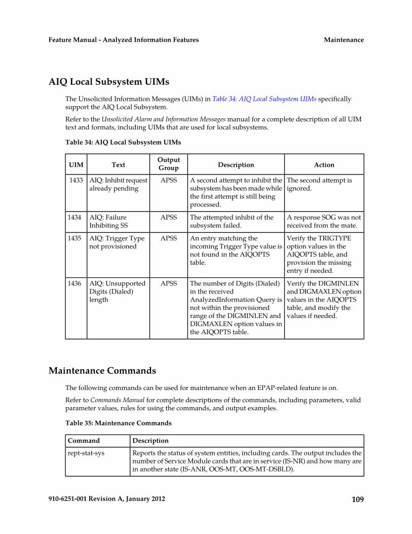
AIQ Local Subsystem UIMs
The Unsolicited Information Messages (UIMs) in Table 34: AIQ Local Subsystem UIMs specificallysupport the AIQ Local Subsystem.
Refer to the Unsolicited Alarm and Information Messages manual for a complete description of all UIMtext and formats, including UIMs that are used for local subsystems.
Table 34: AIQ Local Subsystem UIMs
ActionDescriptionOutputGroupTextUIM
The second attempt isignored.
A second attempt to inhibit thesubsystem has been made whilethe first attempt is still beingprocessed.
APSSAIQ: Inhibit requestalready pending
1433
A response SOG was notreceived from the mate.
The attempted inhibit of thesubsystem failed.
APSSAIQ: FailureInhibiting SS
1434
Verify the TRIGTYPEoption values in the
An entry matching theincoming Trigger Type value is
APSSAIQ: Trigger Typenot provisioned
1435
AIQOPTS table, andnot found in the AIQOPTStable. provision the missing
entry if needed.
Verify the DIGMINLENand DIGMAXLEN option
The number of Digits (Dialed)in the received
APSSAIQ: UnsupportedDigits (Dialed)length
1436
values in the AIQOPTStable, and modify thevalues if needed.
AnalyzedInformation Query isnot within the provisionedrange of the DIGMINLEN andDIGMAXLEN option values inthe AIQOPTS table.
Maintenance Commands
The following commands can be used for maintenance when an EPAP-related feature is on.
Refer to Commands Manual for complete descriptions of the commands, including parameters, validparameter values, rules for using the commands, and output examples.
Table 35: Maintenance Commands
DescriptionCommand
Reports the status of system entities, including cards. The output includes thenumber of Service Module cards that are in service (IS-NR) and how many arein another state (IS-ANR, OOS-MT, OOS-MT-DSBLD).
rept-stat-sys
109910-6251-001 Revision A, January 2012
MaintenanceFeature Manual - Analyzed Information Features

DescriptionCommand
Reports operating status of services and subsystems, CPU usage, and ServiceModule card status. When the loc parameter is specified, the command displays
rept-stat-sccp
detailed card traffic statistics, including cards that are denied SCCP service.See the section in this manual that describes the use of the rept-stat-sccpcommand.
Displays the overall status of the EPAP application running on the MPS(multi-purpose server). Command output for the various reports of this
rept-stat-mps
command include overall MPS alarm status and card status, and status for aspecific Service Module card when a feature is on.
Includes a summary of any trouble notifications (UAMs) for local subsystems,cards, and linksets. The severity of each alarm is indicated in the output report.
rept-stat-trbl
Displays the alarm counts and totals for local subsystems and Service Moculecard/EPAP IP links.
rept-stat-alm
Displays the status information for the EAGLE 5 ISS databases. This includesthe level information for each Service Module card, and for the active and
rept-stat-db
standby EPAP RTDB. The command reports database exception status suchas corrupted, incoherent, or inconsistent, as well as providing the birth datesand levels. It shows the status of each PDB and RTDB when an EPAP-relatedfeature is enabled.
Retrieves table use capacity summary information. For each table listed, thenumber of table entry elements in use and the total allowed number of table
rtrv-tbl capacity
elements is presented, along with a percent (%) full value. Information is shownfor some tables only if the feature that uses the table is enabled.
The inh-card command is used to change the operating state of the cardfrom In-Service Normal (IS-NR) to Out-of-Service Maintenance-Disabled
inh-card/alw-card
(OOS-MT-DSBLD). A craftsperson then can test the card or physically removeit from the shelf.
The alw-card command is used to change the card from OOS-MT-DSBLD(Out-of-Service Maintenance-Disabled) to IS-NR (In-Service Normal) if cardloading is successful.
Used to allow and inhibit reporting of alarms for a given device, including theService Module card ports. The commands allow both Port A and Port B to be
inh-alm/unhb-alm
specified. Inhibited alarms will not generate UAMs or cause alarm indicatorsto be turned on. All rept-stat-xxx commands continue to display the alarmswith an indication that the device has its alarms inhibited.
Retrieves Entity data, DN data, IMEI data, IMSI data, TN data, NPANXX data,and LRN data from the RTDB on an active Service Module card.
rtrv-data-rtdb
If the loc parameter is specified and the target card is an active Service Modulecard, the RTDB data is retrieved from that card.
If the loc parameter is not specified, the RTDB data is retrieved on the activeService Module card that has the lowest IMT address.
110910-6251-001 Revision A, January 2012
MaintenanceFeature Manual - Analyzed Information Features

DescriptionCommand
The RTDB status on the active Service Module card can be coherent orincoherent.
rept-stat-sccp
The rept-stat-sccp command provides statistics for Service Module cards and for the servicesthat execute on the cards. The statistics can be displayed for all Service Module cards, or for a specifiedcard.
Refer to the Commands Manual for a description of the rept-stat-sccp command, includingparameter names, valid values, and output examples for the command.
IAR Base Feature Statistics
The rept-stat-sccp command counts and displays the following statistics when the IAR Basefeature is enabled and turned on:
• TOTAL = the total number of messages for which the IAR Base feature is selected for processing.TOTAL = ERRORS plus SUCCESS plus REROUTE/WARNINGS.
• SUCCESS = the number of messages that passed pre-NPP processing, NPP processing, and post-NPPprocessing without being dismissed, and were modified before being routed to the destination.
• WARNINGS = the number of messages for which a UIM (1020, 1021, 1427-1431) was generated,indicating messages that were not counted in SUCCESS.
• ERRORS = the number of messages that were not counted in SUCCESS and a UIM was not countedin WARNINGS. The problem could be that the message was dismissed, or that a routing failureoccurred on a message that was not dismissed.
• FORWARD TO GTT = the total number of GT-routed messages that were sent for GTT processingby the IAR Base feature processing.
Debug Commands
The Commands Manual contains descriptions of debug commands that can be used in assessing andmodifying system status and operation. Most of the debug commands are used only under the directionof Tekelec support personnel.
The ent-trace command can be used to trace MSUs sent to Service Module cards that are runningthe VSCCP application. The EAGLE 5 ISS traps MSUs that meet the specified tracing criteria, whichinclude DN, some point codes, Entity ID, and message verification and message processing errors.
Status Reporting and Problem Identification
EAGLE 5 ISS commands can be used to obtain status and statistics for the EAGLE 5 ISS system, theEPAP systems, system devices including Service Module cards, EPAP-related features, local subsystems,and SCCP services.
111910-6251-001 Revision A, January 2012
MaintenanceFeature Manual - Analyzed Information Features

Refer to the Commands Manual for complete descriptions of the commands, including parameters andvalid values, rules for using the commands correctly, and output examples.
Refer to the Unsolicited Alarm and Information Messages manual for descriptions and recovery proceduresfor UAMs and UIMs.
Refer to the EPAP Administration Manual for descriptions of EPAP functions and operation.
Refer to the EPAP Alarms on the T1200 Platform manual for descriptions and recovery procedures forEPAP alarms.
Refer to the appropriate Feature Manual for information about the functions and operation ofEPAP-related features.
Table 36: Status Reporting for EPAP-Related Features
CommandReports, Status, and Statistics
EAGLE 5 ISS
rept-stat-sysMaintenance Status Report - indicates whetherMaintenance, Routing, and SCCP Baselines havebeen established.
rept-stat-sysAlarms and operating state for system devices,including Service Module ( "SCCP") cards.
rept-stat-almUnsolicited Alarm Messages (UAMs) andUnsolicited Information Messages (UIMs)
rept-stat-trbl
EPAP/MPS (from the EAGLE 5 ISS)
rept-stat-mpsEPAP code version and operating state for eachEPAP.
rept-stat-mpsMPS hexadecimal alarm strings for the active andstandby EPAPs.
rept-stat-mpsOperating state and alarm status of equippedService Module cards and their DSM ports andIP connections. rept-stat-mps:loc=<Service Module card location>
rept-stat-mps:loc=<Service Modulecard location>
Amount of memory used by the RTDB on thespecified card, as a percent of available ServiceModule card memory.
rept-stat-dbEPAP Provisioning Database (PDB), EPAP RealTime Database (RTDB), and Service Module card
rept-stat-db:db=mpsRTDB status information - Coherent, birthdate
112910-6251-001 Revision A, January 2012
MaintenanceFeature Manual - Analyzed Information Features

CommandReports, Status, and Statistics
(date and time of creation), and exception(condition when a problem was detected).
Service Module Cards, EPAP-Related Features, Services, Local Subsystems
rept-stat-sccpStatus of the Service Module cards, and theservices executing on the cards for EPAP-relatedfeatures that are turned on. Includes ServiceReport, Subsystem Report, and Alarm Status;Total Service Statistics.
rept-stat-mps:loc=<Service Modulecard location>
Operating state and alarm status of equippedService Module cards and their DSM ports andIP connections; EPAP-related feature status percard.
rept-stat-sysAlarms and operating state for Service Module ("SCCP") cards.
rept-stat-mps
rept-stat-sccpAny cards that are denied SCCP service.
rept-stat-sccp:loc=<Service Modulecard location>
Detailed view of the status of SCCP servicesprovided by the specified Service Module card.Includes Card Alarm Status, Card ServiceStatistics
rept-stat-sccp:mode=perfGeneral SCCP traffic performance for ServiceModule cards. Message rates for TVGperformance.
rept-stat-sccpStatistics for EPAP-related feature localsubsystems - Subsystem Report
rept-stat-sccpStatistics for EPAP-related features
EPAP Status and Alarm Reporting
Because EPAP has no direct means of accepting user input or displaying output messages on EAGLE5 ISS terminals, EPAP maintenance, measurements, and status information are routed through aService Module card. EPAP sends two types of messages to the Service Module card: EPAP MaintenanceBlocks and DSM Status Requests and DSM Status Messages. Each message type is discussed in thefollowing sections.
113910-6251-001 Revision A, January 2012
MaintenanceFeature Manual - Analyzed Information Features

EPAP Maintenance Blocks
The EPAP forwards all status and error messages to the Service Module cards in maintenance blocks.Maintenance blocks are asynchronously sent whenever the EPAP has something to report. The statusinformation that is displayed when a rept-stat-mps command is issued includes information thatcame from the maintenance blocks.
The active EPAP generates and sends maintenance blocks to the primary Service Module card. Onemaintenance block is sent as soon as the IP link is established between the active EPAP and the primaryService Module card. Additional maintenance blocks are sent whenever the EPAP needs to report anychange in status or error conditions. The information returned in maintenance blocks is included inthe output of the rept-stat-mps and rept-stat-sccp commands.
The EPAP sends maintenance blocks that contain at least the following information:
• Status of EPAP 'A' - actual states are active, standby, and down (inoperative). Maintenance blocksinclude a field for this information so that it can be available for the output of the rept-stat-mpscommand.
• Status of EPAP 'B' - actual states are active, standby, and down (inoperative). Maintenance blocksinclude a field for this information so that it can be available for the output of the rept-stat-mpscommand.
• Identification of Active EPAP - a field to identify the active EPAP.• Congestion Indicator - an indicator showing provisioning link congestion. The link between the
EPAPs and the external source of provisioning data can become congested in high-provisioningtraffic situations. When this occurs and subsequently as the congestion clears, the EPAP sendsmaintenance blocks to the Service Module card.
• Alarm Conditions - an error code field. If the EPAP needs to report an alarm condition, it puts anappropriate UAM identifier in this field.
• Current MPS Database Size - a field indicating the current RTDB size. The Service Module carduses this information to calculate the percentage of memory used by the RTDB.
DSM Status Requests and DSM Status Messages
When the EPAP needs to know the status of a Service Module card, it sends a DSM Status Request toall Service Module cards, and each Service Module card returns its status to the EPAP.
Service Module cards send a DSM Status Message to the EPAP when any the following events occurin the Service Module card:
• The Service Module card is booted.• The Service Module card receives a DSM Status Request message from the EPAP• The Service Module card determines that it needs to download the entire RTDB; for example, the
Service Module card determines that the RTDB needs to be downloaded because it is totallycorrupted, or a craftsperson requests that the RTDB be reloaded. The Service Module card sendsa Full Download Request message to the EPAP
• The Service Module card starts receiving RTDB downloads or updates. When a Service Modulecard starts downloading the RTDB or accepting updates, it sends a DSM Status Message informingthe EPAP of the first record received. This helps the EPAP keep track of downloads in progress.
The DSM Status Message provides the following information to the EPAP:
114910-6251-001 Revision A, January 2012
MaintenanceFeature Manual - Analyzed Information Features

• DSM Memory Size. When the Service Module card is initialized, it determines the amount ofmemory present. The EPAP uses the value to determine if the Service Module card has enoughmemory to hold the RTDB.
Refer to the Dimensioning Guide for EPAP Advanced DB Features for important information on thedimensioning rules and the Service Module card database capacity requirements.
• Load Mode Status. This indicator indicates whether or not a sufficient number of the IS-NR(In-Service Normal) LIMs have access to SCCP services.
115910-6251-001 Revision A, January 2012
MaintenanceFeature Manual - Analyzed Information Features

GlossaryA
AnalyzedInformation QueryAIQ
Name for the local subsystem andservice for the ANSI41 AIQ feature.
The short name for the ANSI-41AnalyzedInformation Query.
ANSI41 AIQ
B
Binary Coded DecimalBCD
C
Code Division Multiple AccessCDMA
A channel access method used byradio communication technologies.CDMA employs spread-spectrumtechnology and a special codingscheme (where each transmitter isassigned a code) to allow multipleusers to be multiplexed over thesame physical channel. CDMA, themost common cellular wirelesstechnology deployed in NorthAmerica, is being replaced by GSM.See also GSM.
D
Directory numberDN
A DN can refer to any mobile orwireline subscriber number, and caninclude MSISDN, MDN, MIN, or thewireline Dialed Number.
E
Features that require EPAPconnection and use the Real Time
EPAP-related features
Database (RTDB) for lookup ofsubscriber information.
116910-6251-001 Revision A, January 2012

E
• ANSI Number Portability Query(AINPQ)
• ANSI-41 AnalyzedInformationQuery – no EPAP/ELAP(ANSI41 AIQ)
• Anytime Interrogation NumberPortability (ATI NumberPortability, ATINP)
• AINPQ, INP, G-Port SRI Queryfor Prepaid, GSM MAP SRIRedirect, IGM, and ATINPSupport for ROP
• A-Port Circular Route Prevention(A-Port CRP)
• Equipment Identity Register(EIR)
• G-Flex C7 Relay (G-Flex)• G-Flex MAP Layer Routing
(G-Flex MLR)• G-Port SRI Query for Prepaid• GSM MAP SRI Redirect to
Serving HLR (GSM MAP SRIRedirect)
• GSM Number Portability(G-Port)
• IDP A-Party Blacklist• IDP A-Party Routing• IDP Relay Additional Subscriber
Data (IDPR ASD)• IDP Relay Generic Routing
Number (IDPR GRN)• IDP Service Key Routing (IDP SK
Routing)• IDP Screening for Prepaid• INAP-based Number Portability
(INP)• Info Analyzed Relay Additional
Subscriber Data (IAR ASD)• Info Analyzed Relay Base (IAR
Base)• Info Analyzed Relay Generic
Routing Number (IAR GRN)• Info Analyzed Relay Number
Portability (IAR NP)• INP Circular Route Prevention
(INP CRP)
117910-6251-001 Revision A, January 2012
GlossaryFeature Manual - Analyzed Information Features

E
• IS41 Mobile Number Portability(A-Port)
• IS41 GSM Migration (IGM)• MNP Circular Route Prevention
(MNPCRP)• MO-based GSM SMS NP• MO-based IS41 SMS NP• MO SMS Generic Routing
Number (MO SMS GRN)• MO- SMS B-Party Routing• MO SMS IS41-to-GSM Migration• MT-based GSM SMS NP• MT-based GSM MMS NP• MT-based IS41 SMS NP• MTP Routed Messages for SCCP
Applications (MTP Msgs forSCCP Apps)
• MTP Routed Gateway ScreeningStop Action (MTPRTD GWS StopAction)
• Portability Check for MO SMS• Prepaid IDP Query Relay (IDP
Relay, IDPR)• Prepaid SMS Intercept Phase 1
(PPSMS)• Service Portability (S-Port)• S-Port Subscriber Differentiation• Triggerless ISUP Framework
Additional Subscriber Data (TIFASD)
• Triggerless ISUP FrameworkGeneric Routing Number (TIFGRN)
• Triggerless ISUP NumberPortability (TIF NP)
• Triggerless ISUP FrameworkNumber Substitution (TIF NS)
• Triggerless ISUP Framework SCSForwarding (TIF SCSForwarding)
• Triggerless ISUP FrameworkSimple Number Substitution (TIFSNS)
• Voice Mail Router (V-Flex)
I
118910-6251-001 Revision A, January 2012
GlossaryFeature Manual - Analyzed Information Features

I
Internet ProtocolIP
IP specifies the format of packets,also called datagrams, and theaddressing scheme. The networklayer for the TCP/IP protocol suitewidely used on Ethernet networks,defined in STD 5, RFC 791. IP is aconnectionless, best-effort packetswitching protocol. It providespacket routing, fragmentation andre-assembly through the data linklayer.
L
Long Term EvolutionLTE
The next-generation network beyond3G. In addition to enabling fixed tomobile migrations of Internetapplications such as Voice over IP(VoIP), video streaming, musicdownloading, mobile TV, and manyothers, LTE networks will alsoprovide the capacity to support anexplosion in demand forconnectivity from a new generationof consumer devices tailored to thosenew mobile applications.
M
Message Flow ControlMFC
Multi-Purpose ServerMPS
The Multi-Purpose Server providesdatabase/reload functionality and avariety of high capacity/high speedoffboard database functions forapplications. The MPS resides in theGeneral Purpose Frame.
Messages Per Second
A measure of a message processor’sperformance capacity. A message isany Diameter message (Request or
119910-6251-001 Revision A, January 2012
GlossaryFeature Manual - Analyzed Information Features
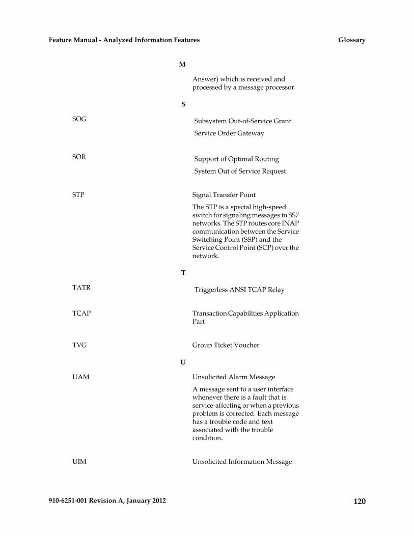
M
Answer) which is received andprocessed by a message processor.
S
Subsystem Out-of-Service GrantSOG
Service Order Gateway
Support of Optimal RoutingSOR
System Out of Service Request
Signal Transfer PointSTP
The STP is a special high-speedswitch for signaling messages in SS7networks. The STP routes core INAPcommunication between the ServiceSwitching Point (SSP) and theService Control Point (SCP) over thenetwork.
T
Triggerless ANSI TCAP RelayTATR
Transaction Capabilities ApplicationPart
TCAP
Group Ticket VoucherTVG
U
Unsolicited Alarm MessageUAM
A message sent to a user interfacewhenever there is a fault that isservice-affecting or when a previousproblem is corrected. Each messagehas a trouble code and textassociated with the troublecondition.
Unsolicited Information MessageUIM
120910-6251-001 Revision A, January 2012
GlossaryFeature Manual - Analyzed Information Features

U
A message sent to a user interfacewhenever there is a fault that is notservice-affecting or when a previousproblem is corrected. Each messagehas a trouble code and textassociated with the troublecondition.
121910-6251-001 Revision A, January 2012
GlossaryFeature Manual - Analyzed Information Features