features of the centrifugal pump - 弗里森 fristam 弗里森泵...
TRANSCRIPT

Centrifugal pumps are f luid- kinet ic machines designed for power increase within a rotat ing
impeller. Therefore it is also called the hydrodynamic pumping principle.
According to this principle, the f luid is accelerated through the impeller. In the out let
connect ion of the centrifugal pump, the result ing increase in speed is converted into
delivery head.
Features of thecentrifugal pump离心泵的特征 离心泵是一种动力使旋转叶轮转动,使动的流体流动的机器,这被称为水力泵送原理
依据此原理,流体加速流过叶轮,在出口处增加的速度被称为压力差
In centrifugal pumps the delivery head H depends on the f low rate Q. This relat ionship, also
called pump performance, is illust rated by curves.
During a bench test , the pump is operated at constant speed and the values Q and H are
determined for the various operat ing points. In order to allow a comparison between the
various pump types these measurements are carried out using only water as liquid. With
these operat ing points a Q/H curve be drawn connect ing the points on the graph.
Once the f low rate Q is def ined and the delivery head H is calculated, the operat ing point
of the plant can be determined. Usually the operat ing point is not on the Q/H curve of the
pump. Depending on the required delivery head, the centrifugal pump will f ind its operat-
ing point when the plant curve and pump curve meet . The f low rate rises f rom Q1 to Q2.
Q/H curveQ/H曲线
在离心泵中水头H与流量Q相关,这种关系被称为泵的特性,用曲线图表示
在基本测试中,泵以恒定转速工作,这样Q和H是一系列变化的工作点
为了便于比较各规格的泵,我们只用水体流体。
Q/H曲线上的工作点被连接起来
一旦流量Q确定,那么水头H即计算出,设备的工作点即被确定通常工作点不在Q/H�曲线上
根据必需的水头,当设备曲线与泵曲线相交的工作点即是离心泵的工作点,流量从Q1升到Q2

Centrifugal pumps
The required operat ing point is obtained by adapt ing the pump to the specif ied operat ing
condit ions.
This can be done by the following act ions:
• throt t ling the f low
• correct ing the diameter of the impeller
• Adjust ing the speed of the drive
Partially closing a throt t le valve or mount ing an orif ice plate into the discharge pipe of the
pump will increase the pressure drop. The plant curve is shif ted.
The operat ing point B1 (intersect ion point between pump curve and plant curve) moves on
the pump curve to B2.
Note: throt t ling reduces the overall ef f iciency.
A throt t le control or a mounted orif ice plate is the less expensive control regarding the
investment expenses. In case of signif icant power requirement , an economic appraisal is
highly recommended.
The f rict ion loss in an orif ice plate can be calculated easily:
ρ [kg/m≈]
v1 [m/s]
∆pv [bar]
Throttling the flow
Orifice platecalculation
这些必需的工作点是泵在设定工作条件下获得的
这些将在下列行为中完成
节流
选择正确的叶轮尺寸
调节进给转速
节流关小节流阀或在泵的排出管上放一个锐口板,将增大压差,设备曲线也将变化
工作点B1(泵曲线与设备曲线的交叉点)移到B2
节流将降低全部的效率
节流或装锐口板是很经济的控制方法,是应该被推荐的
锐口板的摩擦损失是很容易计算出的
锐口板的计算

Centrifugal pumps
See the values ζ stated in the table below.
Calculat ion:
• take the f igure stated in the table for d, see table ζ ,calculate ∆ pV .
• if ∆pV varies f rom the required value, take new value for d and calculate once more ∆pV .
A correct ion of the impeller diameter is to be favoured when a permanent reduct ion of
f low rate or dif ferent ial head is required. The performance of the pump is adjusted towards
the duty point by reducing the impeller diameter.
The operat ing point is shif ted f rom B1 to B2. This is the point where the new pump curve
meets the plant curve.
The required impeller diameter can be determined easily using following formulae:
Note: the ef f iciency of the pump decreases with increasing correct ion.
Correction of theimpeller diameter
N = power consumt ion
D = impeller diameter
Q = f low rate
H = total head
值ζ在下表定出
修区叶轮直径
通常定比值找出ζ,计算出Pv。
如果Pv变化,给出d值计算出新的Pv值
当有永久性流量变化和压力变化时,
修区叶轮直径是有利的,减小叶轮直径将使泵的性能调整到重要的点
工作点从B1转移到B2,这是新的泵曲线与设备曲线交叉点
所需的叶轮直径将被下列公式很容易的定出N 功耗
D 叶轮直径
Q 流量
总压头
泵的效率将随着修正的增加而降低的

Centrifugal pumps
Pump speed controlA great number of various operat ing points can be set cont inuously, when modifying the
pump speed using a variable speed drive or f requency inverter. The operat ing point moves
on the pump curve f rom B to B2.
Considering the overall ef f iciency, this is the best way of f low control. Using a variable-
speed drive or a f requency inverter addit ional costs can arise and should be evaluated in an
economic appraisal.
The f low rate changes linearly to the speed.
The total head changes with the square of
speed.
The power consumpt ion changes with the
third power of the speed.
Parallely connectedpumps
In the case of pumps connected in parallel the f luid f lows are added with corresponding
delivery head. This applies to pumps even with dif ferent Q/H curve.
泵的转速控制
当用变速马达或变频器改变泵转速时,许多变化的工作点将被连续设置
工作点在泵曲线上从B1变为B2
考虑到全面的效率,这是流量控制的最佳方法。使用变速马达或变频器
会增加额外的成本,可以从经济学上评估下
流量变化与转速成正比
总压头与转速成正比
功耗与转速成正比
泵的并联泵的并联将使在相应的压力下流量增加,将导致泵有不同的Q/H曲线

Centrifugal pumps
A mult istage centrifugal pump performs as single stage pumps connected in series.
Note:
A stat ionary pump in a system creates a considerable pressure drop. Therefore it is
recommendable to install a by pass around pumps which are connected in series.
The overall performance curve of centrifugal pumps connected in series can be calculated
by adding the dif ferent ial head of each pump at the relevant f low rate .
Cavitat ion can be recognised by a st rongly increased noise level of the pump with a
simultaneous reduced f low rate.
What causes cavitat ion in centrifugal pumps ?
The lowest pressure point in a pump occurs at the inlet of the pump impeller. Due to local
pressure reduct ion part of the f luid may evaporate generat ing small vapour bubbles. These
bubbles are carried along by the f luid and implode instant ly when they get into areas of
higher pressure. These implosions can create local pressure peaks up to 100.000 bar.
If a pump is cavitat ing over longer periods, the impeller, the pump housing and cover will
wear out . The surface is typically perforated and pit ted.
Pumps connected inseries
Cavitation
泵的串联
多级离心泵就相当于几个单独的泵串联在一起
当需要产生很大的压力F,把泵串联在一起是可取的
在相应的流量下把各个泵不同的压头相加,能计算出串联泵总的性能曲线
气蚀 气蚀发生时通常伴随着渐增的噪声
什么原因导致了离心泵发生气蚀?
当极低的压力发生于泵的进口叶轮处时,由于压力剧减将导致流体产生一些小的蒸气泡
这些随着流体的气泡在压力增加时会剧烈的爆破 这些爆破将产生高达100000BAR的局部压力
如果泵长时间在气蚀下,叶轮,泵壳,泵盖将会磨损
表面将会出现典型的穿孔,凹坑

Centrifugal pumps
How to avoid cavitat ion?
We should ensure that at all points of the pump, the f luid pressure is higher than the
vapour pressure at the corresponding temperature. Take the pressure stated in the vapour-
pressure- table of the product to be t ransfered.
The NPSH value of the plant must be at least 0.5 m higher than the NPSH value of the
pump.
For a safe and cavitat ion f ree operat ion the following formular is valid:
NPSHplant > NPSHPump + 0.5 m
The vapour pressure of the product is dependent on the temperature and will rise with
increasing temperature.
If the product is pumped at dif ferent temperatures the maximum vapour pressure should
be used to determine the NPSH value of the plant .
Vapour pressure
如何避免气蚀?
蒸气压力
我们确保泵在各个方面,在相应温度下,流体压力都要大于其蒸气压力
要知道被传送产品的蒸气压力表
设备的NPSH值至少要比泵的NPSH值大0.5
要不产生气蚀,下面的公式是正确的
产品的蒸气压力与温度有关,随着温度的升高而升高
如果泵送不同温度的产品,那要根据最大的蒸气压来确定设备的NPSH值

Centrifugal pumps
The Fristam centrifugal pump range consists of following pump types:
• Fristam centrifugal pump FP
The design principle of the Fristam centrifugal pump FP with open impeller and
opt imised volute guarantees shear sensit ive handling of and minimum heat t ransfer to
the product . Viscosit ies up to 1000 mPa are no problem. The f luid may contain air or gas,
may be homogeneous or contain addit ives. Low NPSH values make it possible to use the
pump also under unfavourable condit ions. The Fristam centrifugal pump FP is designed
as a pump for f looded suct ion and fully suitable for CIP and SIP applicat ion.
Centrifugal pumptypes
• Fristam mult istage centrifugal pump FM
The centrifugal pump FM is designed as a mult istage pump especially developed for high
delivery heads. The centrifugal pump FM can be used for dif f icult pressure condit ions
such as feed pump for f ilters, heat exchangers and f illers, as well as for recirculat ion and
as booster pump in membrane f ilt rat ion and reverse osmosis plants.
• Fristam self - priming centrifugal pump FZ
The centrifugal pump FZ works on the water ring-side channel principle. Impellers with
radial blades t ransfer the pressure energy to the liquid. Close clearances make it possible
to obtain an excellent suct ion performance. Thus it is possible to pump gaseous prod-
ucts and to deaerate the suct ion line. This ensures also an opt imum drain of the plant ..
离心泵的型号 Fristam离心泵系列由下列型号组成:
Fristam的FP离心泵是开式叶轮,有最优化的涡型设计,保证了产品的柔和处理
以及减少了物料的升温问题。可传送粘度高达1000mPas的物料,流体可以含气体或固体颗粒也可以是均质或异质的,低NPSH值,可保证泵在不利环境下工作,
适用淹没抽吸以及CIP/SIP
FM系列是为高压系统设计的多级离心泵,适用于特别的压力场合,如过滤系统,热交换系统
膜滤,反渗透等系统的增压,填料等
自吸式离心泵FZ,采用侧面通道原理,用放射的叶轮来压送流体
密闭的间隙确保卓越的吸入性能,使吸入管既能排气又能吸到带气体的产品
是适宜设备的排水的问题

Centrifugal pumps
The select ion between the pump types FP and FM also depends on the required f low rate.
Selection criteria必需是自吸泵吗?
离心泵 自吸离心泵
离心泵多级离心泵
在FP和间FM依据必需的流量选择

Centrifugal pumps
Selecting the correct size
Example:
Flow rate QA = 90 m≈/h
Total head HA = 75 m
Step 1:
Select the pump size.
FP sizes
Centrifugal pump FP
Size selection
Selected pump size: FP 3552
离心泵FP 选择正确的规格
举例
流量
总压头
步骤1:选择泵的规格
FP的规格
规格选择
选择泵的规格为FP3552

Centrifugal pumps
Step 2:
Enter the operat ing point of your plant into the pump diagram.
If the duty point is not exact ly on the pump curve, the performance of the pump can be
adjusted by throt t ling the f low, reducing the impeller diameter or adjust ing the output
speed of the drive. (see page 21–23)
FP 3552
Impeller diameter result ing f rom the diagram = 230 mm
Centrifugal pump FPperformance diagram
步骤2:在泵的图表中输入设备的工作点
如果点不在泵曲线上,那么可通过节流,减小叶轮直径,调整马达转速
来调整泵的性能
FP离心泵性能图
从图表中选择叶轮直径=230
Centrifugal pumps
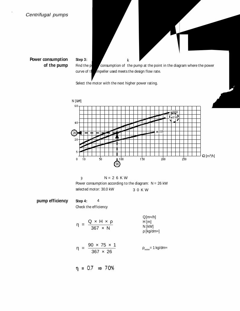
Step 3:
Find the power consumpt ion of the pump at the point in the diagram where the power
curve of the impeller used meets the design f low rate.
Select the motor with the next higher power rat ing.
Power consumpt ion according to the diagram: N = 26 kW
selected motor: 30.0 kW
Step 4:
Check the ef f iciency
η ρ =
Q H N
× ×
×367
η = 90 75 1
367 26
× ××
ρwater= 1 kg/dm≈
Power consumptionof the pump
pump efficiency
Q [m≈/h]H [m]N [kW]ρ [kg/dm≈]
泵的功耗
步骤3:在功率曲线中,用流量与叶轮线相交找到功率
选择更高功率的马达
依照表功耗:N=26KW
选择马达30KW
泵的效率
步骤4:
检查效率

Centrifugal pumps
Step 5:
Check if NPSHplant > NPSHPump
Result ing NPSH value of the pump f rom the diagram = 2.4 m
Check NPSH value检查NPSH值
步骤5:检查是否NPSHpiant>NPSHpump
泵的NPSH值从表中查得=2.4m
Centrifugal pumps
Selecting the correct size
Example:
Flow rate QA= 30 m≈/h
Total head HA= 24 m
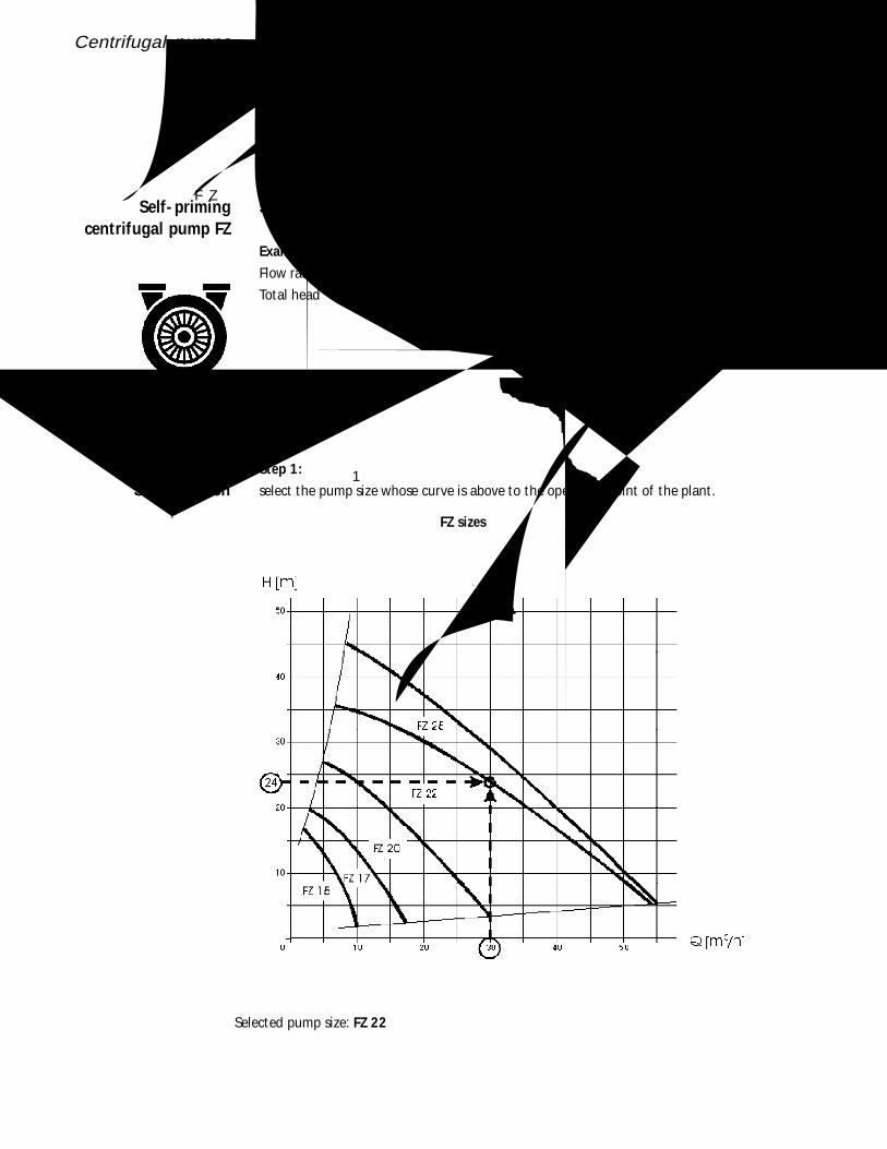
Step 1:
select the pump size whose curve is above to the operat ing point of the plant .
Self- primingcentrifugal pump FZ
Size selection
FZ sizes
Selected pump size: FZ 22
自吸离心泵FZ选择正确的规格
举例
流量
总压头
规格选择
步骤1:在设备的工作点之上曲线选择泵的型号

Centrifugal pumps
Power consumptionof the pump
Note:
The performance of FZ pumps can be adjusted to the required operat ing point only by
throt t ling the f low (see page 21/22) or variat ion of the speed (see page 23). It is not
possible to modify the impeller diameter.
泵的功耗
FZ性能的调整仅能通过节流或变化转速来获得,不可能通过修整叶轮直径来获得

Centrifugal pumps
Multistagecentrifugal pump FM
Step 2:
Find the power consumpt ion of the pump at the point in the diagramm where the power
curve meets the design f low rate. Select the motor with the next higher power rat ing.
From the diagram: N = 6.7 kW, selected motor: 7.5 kW
The select ion is carried out the same way as single-stage centrifugal pumps FP are selected
(See page 28).
步骤2:当设计流量向上功耗曲线的线的值为功耗值,选高的马达功率
从表中:N=6.7KW,选择马达:7.5KW
同选择单级离心泵FP一样来选择多级离心泵