february 8, 2008 cac concrete design handbook, 3 edition ... · 1 february 8, 2008 cac concrete...
TRANSCRIPT

1
February 8, 2008
CAC Concrete Design Handbook, 3rd Edition, Errata To date three printings of the 3rd Edition of the CAC Concrete Design Handbook have been run. Soft Cover, Hard Cover 1st Printing, and Hard Cover 2nd Printing. The Errata contained in this file is listed in four sections. Sections 1, 2, and 3 contain errata on both the Explanatory Notes to A23.3-04 and Chapters 1 to 13 of the Handbook. Appendix “A” contains a subject index to the CSA A23.3-04 Standard which was not included with the 3rd edition of the Handbook. Due to popular request the Index has been regenerated and included here for your information in Appendix “A”.
Which Sections Apply to My Printing of the Handbook ? If you have the: Soft Cover 3rd Edition Handbook: Apply Errata in Sections 1, 2, 3 and Appendix “A”. Hard Cover 3rd Edition 1st Printing: Apply Errata in Sections 2, 3 and Appendix “A”. Hard Cover 3rd Edition 2nd Printing: Apply Errata in Section 3 and Appendix “A” only.
Note: Identification of 1st and 2nd Printing: The second printing of the 3rd edition Hard Cover was erroneously identified on page “ii” as being “First Printing January 2006”. The second printing of the Hard Cover edition can be identified by the presence of two figures, “6.1” and “6.1(a)” on page 6-37, while the first printing will show only one figure “6.1”.

2
SECTION 1
Errata for Soft Cover 3rd Edition
Page 2-26 - Table 2.8
On the right hand side of the figure replace the dimension noted as “2h ” with
“ )(22
dhh−− ”.
Pages 5-2 to 5-48 - Top of Page Replace the heading “Short Columns” at the top of the page with “Slabs”. Chapter 9 Errata Page 9-5 – Revise the last line at the end of section 9.4.3.1 as shown below: Replace “Tables 9.1 to 9.3 include the larger dv calculated from equations (9.2) and (9.3).“ with “Tables 9.1 to 9.3 consider all conditions set out in Clauses 11.3.6.2, 11.3.6.3 and 15.7. When 3d < ab the smallest d value was used calculated based on Clause 11.3.6.3.(b) and ab/3.” Page 9-6 – In the first line at the top of the page under section 9.4.3.2 revise the text “Equation (13.6)” to read “Equation 13-6”. Also revise the 2nd line on page 9-6 as follows: Revise “than Equation (13.7), thus tables 9.4 to 9.6 are based on Equation (13-7).” To read: “than Equation (13-7), thus tables 9.4 to 9.6 are based on Equation (13-7). For consideration of Clause 13.3.4.4 see note under Table 9.4. “ Page 9-22 - In step 2 of “Example 9.7.3 Square Footing” revise: “From Table 9.1 dv = 330 mm, thus d = dv /0.9 = 367 mm” to read “From Table 9.1 dv = 333 mm, thus d = dv /0.9 = 370 mm”

3
Page 9-23 - At the top of the page following the expression for “dave” insert the following line of text: “Since ,0.122.1)406.0(33 mamd bave =>== Clause 13.3.4.4 is not applicable.” Page 9-24 - In the 6th line at the top of the page in step 3.2 of Example 9.7.4 revise the text as follows: Revise “Therefore the minimum depth from the two-way stress condition is d ≥ 1.46(0.5) = 0.73 m. “ to read “Therefore the minimum depth from the two-way stress condition is d ≥ 1.46(0.5) = 0.73
m. Since ,3.12/)5.01.3(19.2)73.0(3 mam b =−=>= Clause 13.3.4.4 is not applicable. “ Page 9-25 – Revise the last line of text on this page as follows: Revise “qsf = 300 kPa, from Table 9.1 dv = 593 mm and d = dv /0.9 = 659 mm. “ to read
“qsf = 300 kPa, from Table 9.1 dv = 600 mm and d = dv /0.9 = 667 mm. “ Page 9-26 - Insert the following line of text between the 6th and 7th lines of text at the top of the page: “Clause 13.3.4.4 is not applicable since .8.176.1)585.0(3 mam b =≅= ”
Page 9-27 - In step 2 revise: “From Table 9.3: dv = 458 + (510 - 458)(8.2)/50 = 467 mm, thus d = dv /0.9 = 519 mm.“ to read “From Table 9.3: dv = 533 mm, thus d = dv /0.9 = 592 mm.“ Page 9-27 - In step 3.1 revise the text as follows: Revise “From Table 9.3: dv = 458 + (510 - 458)(26.8)/50 = 486 mm, thus d = 486/0.9 = 540 mm.“ to read “From Table 9.3: dv = 533 mm, thus d = 533/0.9 = 592 mm.“ Page 9-28 - In step 3.2 revise the 4th and 5th lines of text as follows:

4
“Since he = )500(250Ac = = 354 mm thus d = 1.92(354) = 679 mm > 592 mm, thus two-way shear governs. Use minimum d = 700 mm. Note: Clause 13.3.4.4 is therefore not applicable.” Page 9-30 - Revise the 8th line in step 2.2 as follows: “From the Vr = Vf equation d = 0.705 m ~ 0.7 m. Note: Clause 13.3.4.4 is therefore not applicable.” Page 9-32 – Revise the “Two-Way Shear Figure 9.7.7-3(b)” as shown below. The right hand vertical dashed line has been relocated to the right so that all vertical and horizontal lines intersect the Vr curve at the same point. See below:
Page 9-33 - In Step 2.2 revise the line starting with “The solutions yields d = …” as noted below: “The solution yields d = 568 mm with Vf = 3.13 MN < 8(0.55) = 4.4 MN Note: Clause 13.3.4.4 is therefore not applicable.”

5
Page 9-40 - Add the following note at the bottom of Table 9.4 and also at the bottom of Table 9.6 on Page 9-41 “See page 48 for the note to tables 9.4 to 9.6.” Page 9-48 - Add the following text below Table 9.11: “Note to Tables 9.4 to 9.6 - Tables 9.4 to 9.6 are worked out as described in paragraph 9.4.3.2 of the Handbook. Thus for the given qsf and Af /Ac initial design parameters, a d/he ratio is calculated based on Equation (13-7). Clause 13.3.4.4 however would yield a different/larger d/he value for the same qsf and Af /Ac initial design parameters, for cases where 3d < ab. When 3d < ab the smallest d value shall be used calculated based on Clause 13.3.4.4 and ab/3. Clause 13.3.4.4 (thus Clause 13.3.4.3) in combination with Equation (13-7) results in a cubic equation (refer to Equation 9.4 in the Handbook)” Chapter 11 Errata: Page 11-17 - In the paragraph above Fig 1.9 under the heading “Span AB:” In the second line replace the reference to “(Table 11.7)” with “(Table 11.5)”. Page 11-19 - Top of page. In the second line immediately following Figure 11.10 in the equation ‘ sdfAV yvsr /φ= ” The term “d” should be “dv” to give “ s/dfAV vyvsr φ= ”. Page 11-19 - Top of page. 5th line down.
Replace the equation “ 3061000234
52740040085.0=
××××
=s “ with the following:
“ 2761000234
5279.040040085.0=
×××××
=s ”. The 0.9 factor has been added to the numerator.
This changes the subsequent equation for “ 273306262234
=×=s ” two lines further down
to read: “ 247276262234
=×=s ”.
Page 11-19 - Revise the equations noted below as indicated. The revisions are underlined. Revise: “(iii) Spacing limits (Clause 11.3.8.3): Since kN = x 400 x 30 x 0.6 x 0.1 = d b f 0.1 < V wccf 4625279.052525 ×′φ then 600max =s mm or 3325279.07.07.0 =××=d mm.

6
Note that near the ends of the beams the stirrup spacing required for shear cannot exceed 306 and 273 mm for spans AB and BC, respectively.” to read: “(iii) Spacing limits (Clause 11.3.8.3): Since kN = x 400 x 30 X 0.6 x 0.1 = d b f 0.1 < V vwccf 4625279.052525 ×′φ
then 600max =s mm or 3325279.07.07.0 =××=vd mm. Note that near the ends of the beams the stirrup spacing required for shear
cannot exceed 276 and 247 mm for spans AB and BC, respectively.”
Page 11-19 - in the paragraph under 11.4.4.5: In the 4th line revise “Fig. 11.10” to read “Fig. 11.11”. In the 5th line revise “Clause 21.2.3” to read “Clause 21.3.2.3”. Page 11-19 - in the paragraph under 11.4.4.6: In the 3rd line revise “Fig. 11.11” to read “Fig. 11.10”. Page 11-25 - At the end of the first paragraph under 11.4.5.5 replace “ 164 kN” with “132 kN”. Page 11.27 - In the line following the question for “s” replace the term “theta” with “phi” as follows: Replace “Since fV of 359 kN is less than 439125.0 =′ vwcc dbfλθ kN, then from” With “Since fV of 359 kN is less than 439125.0 =′ vwcc dbfφλ kN, then from”. Page 11-29 - revise the heading: “11.4.6 Design of Interior Beam-Column “ to read “11.4.6 Design of Interior Beam-Column Joint” Page 11-33 - mid page: Revise “Dead loads: self-weight of reinforced concrete members calculated at 24 kN/m3 “ to read “Dead loads: self-weight of members calculated at 24 kN/m3 “ Page 11-34 - in the 1st line under :N-S Direction” revise: “The calculated period for this structure, using the …..” to read “The calculated period for this structure in the N-S direction, using the ….. “ Page 11-35 - in the 1st line under the heading “E-W Direction” revise as follows: “The calculated period for this structure, using the “

7
to read “The calculated period for this structure in the E-W direction, using the “ Page 11-35 -In the sentence preceding the questions for “V” revise “For the ductile coupled wall system in the N-S direction 0.4=dR and 7.1=oR .” to read: “For the ductile coupled wall system in the E-W direction 0.4=dR and 7.1=oR .” Page 11-37 - Revise: “11.5.3.4 Check on Structural Irregularity To determine if the structure is sensitive to torsion, the values of B need to be determined at all levels from the maximum and average displacements of the structure at in the E-W and N-S directions.” to read: “11.5.3.4 Check on Structural Irregularity To determine if the structure is sensitive to torsion, the values of B need to be determined at all levels from the maximum and average displacements of the structure at in the E-W and N-S directions. “ Page 11-39 - Revise the heading of Figure 11.23 as follows: “Figure 11.23 3-D Models used for dynamic analysis “ to read: “Figure 11.23 3-D Model used for dynamic analysis “ Page 11-46 - in the firs paragraph under 11.5.5.1 revise the reference to “(see Tables 11.10 and 11.11). “ to read “(see Tables 11.11 and 11.13). “ Page 11-48 - in the first line following Table 11.14, revise the words “given in Table 11.12, is “ to read “given in Table 11.14, is “: Page 11-50 - at the bottom of the page under heading 11.5.6.3 revise the words: “In regions of plastic hinging, the uniformly distributed horizontal reinforcement must be anchored within the region of concentrated reinforcement to develop yf.251 (Clause 21.6.5.5.1). “ to read “In regions of plastic hinging, the uniformly distributed horizontal reinforcement must be anchored within the region of concentrated reinforcement to develop yf.251 (Clause 21.6.5.5).” Page 11-52 - in item “d” following Fig 11.27 in the 3rd line:

8
Revise the words “The distributed reinforcement ratio must be greater than 0.0025 in each direction. “ to read “The distributed reinforcement ratio must be at least 0.0025 in each direction. “ Page 11-52 - in Table 11-15 in the 3rd row of the 5th column replace “-18509” with “-17663”. Page 11-54 - revise the equation:
025.00278.0002.0435.02
4.80035.0002.02
≤=⎟⎠⎞
⎜⎝⎛ −
××
=⎟⎠⎞
⎜⎝⎛ −=
cwcu
iclε
θ
as follows:
025.00318.0002.0493.02
4.80035.0002.02
≤=⎟⎟⎠
⎞⎜⎜⎝
⎛−
××
=⎟⎠⎞
⎜⎝⎛ −=
cwcu
iclε
θ
Page 11-54 - under the heading “N-S Direction - Ductile Shear Walls (Clause 21.6.7)” revise “For ductile shear walls, the ratio of the nominal flexural resistance to the factored flexural resistance, fM , at the base is 1.95 and hence the inelastic rotational demand idθ is taken as:” to read “For ductile shear walls, the ratio of the nominal flexural resistance to the factored flexural resistance, fM , at the base is 1.9 and hence the inelastic rotational demand idθ is taken as:”
Page 11-54 - revise equations:
“( ) ( ) 004.00033.0
24.60.45
9.1028.05.37.1028.0
2
≥=⎟⎠⎞
⎜⎝⎛ −
×−××=
⎟⎠⎞
⎜⎝⎛ −
∆−∆=
ww
wfdofid
h
RRl
γθ ”
to read
“( ) ( ) 004.00024.0
24.60.45
95.1028.05.36.1028.0
2
≥=⎟⎠⎞
⎜⎝⎛ −
×−××=
⎟⎠⎞
⎜⎝⎛ −
∆−∆=
ww
wfdofid
h
RRl
γθ ”
and revise
9
“ 025.00348.0002.0303.02
4.60035.0002.02
≤=⎟⎠⎞
⎜⎝⎛ −
××
=⎟⎠⎞
⎜⎝⎛ −=
cwcu
iclε
θ ”
to read
“025.00350.0002.0
303.024.60035.0002.0
2≤=⎟
⎠⎞
⎜⎝⎛ −
××
=⎟⎠⎞
⎜⎝⎛ −=
cwcu
iclε
θ”
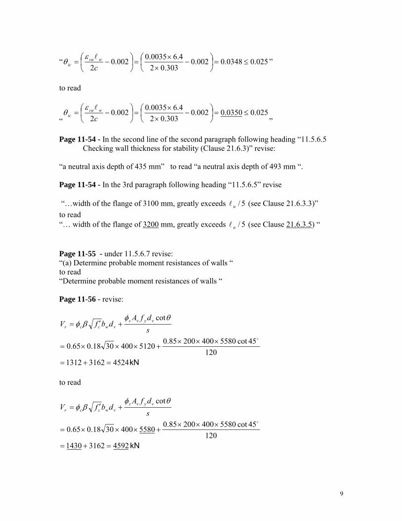
Page 11-54 - In the second line of the second paragraph following heading “11.5.6.5 Checking wall thickness for stability (Clause 21.6.3)” revise: “a neutral axis depth of 435 mm” to read “a neutral axis depth of 493 mm “. Page 11-54 - In the 3rd paragraph following heading “11.5.6.5” revise “…width of the flange of 3100 mm, greatly exceeds 5/ul (see Clause 21.6.3.3)” to read “… width of the flange of 3200 mm, greatly exceeds 5/ul (see Clause 21.6.3.5) “ Page 11-55 - under 11.5.6.7 revise: “(a) Determine probable moment resistances of walls “ to read “Determine probable moment resistances of walls “ Page 11-56 - revise:
kN452431621312120
45cot558040020085.051204003018.065.0
cot
=+=
×××+×××=
+′=
o
sdfA
dbfV vyvsvwccr
θφβφ
to read
kN 459231621430120
45cot558040020085.055804003018.065.0
cot
=+=
×××+×××=
+′=
o
sdfA
dbfV vyvsvwccr
θφβφ

10
Page 11-56 - in the 1st paragraph under “E-W Direction” revise: “with Clause 21.6.8.13 it is necessary to redistribute the shear force “ to read “with Clause 21.6.8.13 it may be necessary to redistribute the shear force “ Page 11-56 - in the expression for Vr under the heading “E-W Direction” revise the expression as follows: “ 4594002002885.025.025.0 =××××== yvsr fAV φ kN” to read
“ 4594002002785.025.025.0 =××××== yvsr fAV φ kN”
Page 11.57 - in the first sentence under the heading “N-S Direction” revise the reference to “Clause 11.6.2” to read “Clauses 11.5.1 and 11.5.2” Page 11-58 - revise the expression for Vr as follows” Revise
MPa 897.13200800100010174000025.00.150.065.0
=
⎟⎟⎠
⎞⎜⎜⎝
⎛⎟⎠⎞
⎜⎝⎛
××
+×+=
⎟⎟⎠
⎞⎜⎜⎝
⎛⎟⎟⎠
⎞⎜⎜⎝
⎛++=
gyvcr A
Nfcv ρµφ
Hence, the sliding shear resistance of segment AB is: 24293200400897.1897.1 =××=× cvA kN.
to read:
MPa 465.13200800100019314000025.00.150.065.0
=
⎟⎟⎠
⎞⎜⎜⎝
⎛⎟⎠⎞
⎜⎝⎛
××
+×+=
⎟⎟⎠
⎞⎜⎜⎝
⎛⎟⎟⎠
⎞⎜⎜⎝
⎛++=
gyvcr A
Nfcv ρµφ
Hence, the sliding shear resistance of segment AB is: 18753200400465.1465.1 =××=× cvA kN”
Page 11-58 - In the heading to section 11.5.6.10 revise the reference to “Clause 21.6.2” to read “Clause 21.6.5”.

11
Page 11-58 - revise the heading: “11.5.6.12 Changes in concentrated vertical reinforcement over the height of the walls“ to read “11.5.6.12 Changes in concentrated vertical reinforcement over the height of the walls (Clause 21.6.6)” Page 11-59 - Immediately following the expression for Vr in section 11.5.7.1 add the following sentence. “A clear cover of 25 mm and 15M top bars are assumed for the slab.“ Page 11-59 - Revise the two equations for Vr as follows: Revise “ ( ) ( )[ ] ( ) 5.6474.0025.34.25.05.18.40.1 22 =−×++=fV kN” to read “ ( ) ( )[ ] ( ) 2.6973.0125.34.25.05.18.40.1 22 =−×++=fV kN” and also revise:
“ ( ) 276.01602/1605501002
10005.64=
×++××
==db
Vv
o
ff ”
to read
“ ( ) 296.01602/1605501002
10002.69=
×++××
==db
Vv
o
ff MPa”
Page 11-60 - revise section 11.5.8 to read as follows:
11.5.8.1 Comparisons with the Design Using the 1994 CSA Standard
The structure designed in this section chapter is the same structure designed in Reference 2, except that the structure designed in this section chapter was for a foundation on soil of site Class D (stiff soil), whereas the structure in Reference 2 was for the same structure founded on rock. In addition, 900 mm deep diagonally reinforced coupling beams were used, instead of 600 mm deep coupling beams with conventional reinforcement. It is noted that, for this structure, the design force levels using the 2005 NBCC are somewhat lower than those using the 1995 NBCC.

12
SECTION 2
Errata for Hard Cover 3rd Edition 1st Printing And Soft Cover 3rd Edition
Note: Identification of 1st Printing: Both the first and second printing of the 3rd edition Hard Cover were erroneously identified on page “ii” as “First Printing January 2006”. The second printing can be identified by the presence of two figures, “6.1” and “6.1(a)” on page 6-37, while the first printing will show only one figure “6.1” on this page. Figure 6.1(a) is included in the errata below.
Page 220 - n Table N3.1.3 in the last row under the column titled “AREA”, replace “2000” with “2500”. Page 244 - in Note N10.15.3 in the 3rd line – revise “CmM2” to read “M2” Page 278 – Note N12.15.1 in the second line replace “Table 12-2” with “Clause 12.15.2”. In the 4th line of the same note replace “The classifications for Table 12-2 require” with “ Clause 12.15.2 requires”. Page 278 – Note 12.15.4. In the second line replace “1.25” with 1.20”. Page 1-15 – At the bottom of the page in the last sentence replace “550” with “500” and replace “Clause 9.4.1” with “Clause 8.5.1”. Page 1-33 – In the expression for “R” replace:
“90100
300.x
R = ” with “ hoursR 33.219.0100
300=−
×= ”
Page 1-37 – Replace the text below as indicated: Replace:
“( Clear side cover at CGS = ” 2432
90199 ..=
− ”
with
“( Clear side cover at CGS = 2.432
7.121.99=
− ”
Page 1-73 – In the right hand column in the second row, replace the second half of the expression for “I” as indicated below: Replace
“RyRyRyR 1122
12
1
2
sin4 ⎥⎦
⎤⎢⎣⎡ +−− − ”

13
with
“ ⎥⎦⎤
⎢⎣⎡ +−− −
RyRyRyR 1122
12
1
2
sin4
”
Page 2-13 – Replace the text below as indicated: ( An “=” sign was missing in line 2, and square root signs were missing in lines, 4, 7, 10 and 11). 5. Check minimum steel requirement:
OKmmA
mmA
EqfhbAEqoflieuinusedbemayEqNote
OKmkNmkNMmmNMconcretedensitynormalmmc
mmbhI
andEqcIMbarsMformkNM
MM
s
s
yts
r
cr
t
tccr
r
crr
2
2min
cmin
4933c
7592500)500(5
759)400(/)600()400()40(2.0
)72.(/ 'f2.0.5272:
109)91(2.141510691)300/()1092.7(40)0.1(6.0
)(0.1;3002/600102.712/)600)(400(12/
)6252.(/'f 0.6255415
2.1
>==
==
−=−−
⋅=>⋅=⋅⋅=⋅=
===⋅===
−−=−⋅=
λ
λ
Replace with: 5. Check minimum steel requirement:
OKmmA
mmA
EqfhbfA
EqoflieuinusedbemayEqNoteOKmkNmkNM
mmNM
concretedensitynormalmmcmmbhI
andEqcIM
barsMformkNM
MM
s
s
ytcs
r
cr
t
tccr
r
crr
2
2min
min
4933
c
7592500)500(5
759)400(/)600()400(402.0
)72.(/'2.0
.5272:109)91(2.1415
10691)300/()1092.7(40)0.1(6.0
)(0.1;3002/600102.712/)600)(400(12/
)6252.(/'f 0.6
255415
2.1
>==
==
−=
−−⋅=>⋅=
⋅⋅=⋅=
===⋅===
−−=
−⋅=
=
λ
λ

14
Page 2-20 - At the top of the page in the numerator of the expression for “Kr” replace “φcfy“ with “φsfy“. Page 2-23 – Revise equation (2.2) as noted below: Replace “ 670002509701 .f.. '
c ≥−=α ” with “ 67.00025.097.0 '1
≥−= cfβ Page 5-2 – At the top of the even numbered pages in Chapter 5 replace the heading “Short Columns” with “Slabs”. Page 5-13 – In the table of design moments, in the 1st row of the 3rd column replace “156” with “160”. Also in the 1st row of the 4th column replace “198” with “185”. Page 6-6 – Revise the figure as shown below. Extend the shorter of the two bottom bars to the end of the span on the left hand side as indicated below.
Page 6-11 – At the bottom of the page, at the end of the second sentence following the heading “Design Example 6.2”, add the text noted below: “Required: Deflection calculations for two-way slab systems with drop panels. Calculations based on specified loads and fr = 0.3 'cf MPa. (See figue 6.1(a)). “
Page 6-37 – Figure 6.1(a) shown below was inadvertently omitted from this page.
Insert Figure 6.1(a) below Figure 6.1 on page 6-37.

15
Fig. 6.1(a)
Page 8-3 – In section 8.2.2 in the 10 line replace “0.5” with “1.0”. Page 8-7 - Revised both the 4th line on this page and equation 8.9 as follows: “Furthermore, the moment Cm M2 should not be less than the moment associated with minimum eccentricity.” “Cm M2 = Pf(15 +0.03h) (8.9)“ Page 8-10 – In Step 5 of Example 8-1 revise the text as follows:
Revise: “Alternatively, EI from Eq 8.7; EI = 0.25 EcIg = 0.25 x 29602 x 5.2 x 109 = 3.8 x 10¹³ N.mm2 “ With “Alternatively, EI from Eq 8.7 for βd = 0.53; EI = 0.26 EcIg = 0.26 x 29602 x 5.2 x 109 = 4.0 x 10¹³ N.mm2 “ Page 8-10 – In the last line on this page delete the term “Cm “ at the start of the line.
Page 8-13 – In step 3 of Example 8-2 replace the text as follows:

16
Replace: “Note: Pc for all load combinations can be computed to be the same if Eq. 8.7 is used
in computing EI, since this expression is independent of βd. Ec = 29602 MPa for f'c = 40 MPa (from Table 8.4) From Eq. 8.7; EI = 0.25 EcIg = 0.25 (29602)(5.2 x 10⁹) = 3.8 x 10¹³ N.mm2 ℓu = 5500 - 750 = 4750 mm “ with “Use Eq. 8.7 for simplicity, with βd = 0.0 for sidesway effects (since the wind
induced shear is not a sustained load) and an assumed value of βd = 0.6 for braced frame effects. Ec = 29602 MPa for f'c = 40 MPa (from Table 8.4) From Eq. 8.7; for sway frames; EI = 0.4 EcIg = 0.4 (29602)(5.2 x 10⁹) = 6.2 x 10¹³ N.mm2 for braced frames; EI=0.4EcIg /(1+βd)=0.25(29602)(5.2 x109)=3.8x10¹³ N.mm2 lu = 5500 - 750 = 4750 mm “
Page 8-13 – In the first line of step 3(i) replace: “Pc = π2EI / (kℓu)2
=π2 (3.8 x 10¹³)/(1.35 x 4750)2 = 9,121 x 103 N for a sway frame. “
with “Pc = π2 EI / (k lu)2 =π2 (6.2 x 10¹³)/(1.35 x 4750)2 = 14,881 x 103 N for a sway frame.
“ Page 8-13 – In the first line of step 3(ii) replace: “Pc = π2EI / (kℓu)2
= π2 (3.8 x 10¹³) / (1.15 x 4750) 2 = 12,569 x 103 N for a sway frame. “
with “Pc = π2 EI / (k lu )2 = π2 (6.2 x 10¹³) / (1.15 x 4750)2 = 20,507 x 103 N for a sway frame. “
Page 8-14 – In step 4(i)(a) at the top of the page, revise the text below as indicated.
The revisions are underlined. Replace
“a) Sway magnification factor δs from Eq. 8.12. ΣPf = 4 (2359 + 18) + 10 (3375 + 26) + 6 (5287 + 6) = 75276 kN From Step 3; ΣPc = 10 (9121) + 10 (12569) = 216900 kN δs = 1 / [1 - ΣPf / (φm ΣPc )] = 1 / [1 - 75276 / (0.75 x 216900)] = 1.86 δs M1s = 1.86 x 43 = 80 kN.m δs M2s = 1.86 x 63 = 117 kN.m b) Compute design moments M1 and M2 from Eqs. 8.10 and 8.11, and Table 8.7. M1 = M1ns + δs M1s = 226 + 80 = 306 kN.m M2 = M2ns + δs M2s = 239 + 117 = 356 kN.m “
With “a) Sway magnification factor δs from Eq. 8.12.

17
ΣPf = 4 (2359 + 18) + 10 (3375 + 26) + 6 (5287 + 6) = 75276 kN From Step 3; ΣPc = 10 (14881) + 10 (20507) = 353880 kN δs = 1 / [1 - 3Pf / (φm ΣPc )] = 1 / [1 - 75276 / (0.75 x 353880)] = 1.40 δs M1s = 1.40 x 43 = 60 kN.m δs M2s = 1.40 x 63 = 88 kN.m b) Compute design moments M1 and M2 from Eqs. 8.10 and 8.11, and Table 8.7. M1 = M1ns + δs M1s = 226 + 60 = 286 kN.m M2 = M2ns + δs M2s = 239 + 88 = 327 kN.m “
Page 8-14 – In step 4(ii)(a) Revise the text as indicated. Revisions are underlined. Revise
“a) Sway magnification factor δs and magnified sway moments δs M1s and δs M2s ΣPf = 4 (1850 + 64) + 10 (2646 + 91) + 6 (4143 + 21) = 60010 kN From Step 3: ΣPc = 10 (9121) + 10 (12569) = 216900 kN δs = 1 / [1 - ΣPf / (φm ΣPc )] = 1 / [1 - 60010 / (0.75 x 216900)] = 1.58 δs M1s = 1.58 x 152 = 240 kN.m δs M2s = 1.58 x 220 = 348 kN.m b) Compute design moments M1 and M2 from Eqs. 8.10 and 8.11, and Table 8.7. M1 = M1ns + δs M1s = 177 + 240 = 417 kN.m M2 = M2ns + δs M2s = 188 + 348 = 536 kN.m “
with
“a) Sway magnification factor δs and magnified sway moments δs M1s and δs M2s ΣPf = 4 (1850 + 64) + 10 (2646 + 91) + 6 (4143 + 21) = 60010 kN From Step 3; ΣPc = 10 (14881) + 10 (20507) = 353880 kN δs = 1 / [1 - ΣPf / (φmΣPc )] = 1 / [1 - 60010 / (0.75 x 353880)] = 1.29 δs M1s = 1.29 x 152 = 196 kN.m δs M2s = 1.29 x 220 = 284 kN.m b) Compute design moments M1 and M2 from Eqs. 8.10 and 8.11, and Table 8.7. M1 = M1ns + δs M1s = 177 + 196 = 373 kN.m M2 = M2ns + δs M2s = 188 + 284 = 472 kN.m “
Page 8-15 – In step 4(i)(a) Revise the text as indicated. The revised numbers are
underlined. Revise
“ΣPf = 4 (1788) + 10 (2555) + 6 (4000) = 56702 kN From Step 3; ΣPc = 10 (9121) + 10 (12569) = 216900 kN

18
δs = 1 / [1 - ΣPf / (φmΣPc )] = 1 / [1 - 56702 / (0.75 x 216900)] = 1.54 δs = 1.54 < 2.5 O.K. “
with
“ΣPf = 4 (1788) + 10 (2555) + 6 (4000) = 56702 kN From Step 3; ΣPc = 10 (14881) + 10 (20507) = 353880 kN δs = 1 / [1 - ΣPf / (φmΣPc )] = 1 / [1 - 56702 / (0.75 x 353880)] = 1.27 δs = 1.27 < 2.5 O.K. “
Page 8-16 – At the top of the page revise the text as indicated. The revised numbers
are underlined. Revise
“ΣPf = 4 (2359) + 10 (3375) + 6 (5287) = 74908 kN From Step 3; ΣPc = 10 (9121) + 10 (12569) = 216900 kN δs = 1 / [1 - ΣPf / (φmΣPc )] = 1 / [1 - 74908 / (0.75 x 216900)] = 1.85 δs = 1.85 < 2.5 O.K. “
with
“ΣPf = 4 (2359) + 10 (3375) + 6 (5287) = 74908 kN From Step 3; ΣPc = 10 (14881) + 10 (20507) = 353880 kN δs = 1 / [1 - ΣPf / (φmΣPc )] = 1 / [1 - 74908 / (0.75 x 353880)] = 1.39 δs = 1.39 < 2.5 O.K.”
Page 8-16 – In the right hand column of the Summary of Design Loads table revise
the “356” to read “327” and revise “536” to read “472”. Page 8-16 – Revise the text below the table as shown below: Revise
“Select the interaction diagrams given in Table 7.4.15 from Chapter 7. For Load Combination II; Pf/Ag = 2737 x 103 / (500)2 = 11.0 MPa Mf/Agh = 536 x 106 / (500)3 = 4.3 MPa Select ρt = 0.02. Ast = 0.02 (500)2 = 5000 mm2. Try 30M bars (Ast = 700 mm2); 5000 / 700 = 7.14. Use 8 - 30M bars equally distributed on all four faces. Check the capacity for Load Combination I; Pf/Ag = 3401 x 103 / (500)2 = 13.6 MPa Mf/Agh = 356 x 106 / (500)3 = 2.8 MPa the point lies inside the interaction diagram, O.K. Note: For further details of cross-sectional design refer to Chapter 7.“

19
with
“Select the interaction diagrams given in Table 7.4.14 and 7.4.15 from Chapter 7 and interpolate for γ =375/500 = 0.75.
For Load Combination II; Pf/Ag = 2737 x 103 / (500)2 = 11.0 MPa Mf/Agh = 472 x 106 / (500)3 = 3.8 MPa From Table 7.4.14 for γ = 0.70; select ρt = 0.017. From Table 7.4.15 for γ = 0.80; select ρt = 0.015. Interpolate for γ = 0.75; ρt = 0.016. Ast = 0.016 (500)2 = 4000 mm2. Try 25M bars (Ast = 500 mm2); 4000 / 500 = 8.0; Use 8 -25M bars equally distributed on all four faces. Check the capacity for Load Combination I; Pf/Ag = 3401 x 103 / (500)2 = 13.6 MPa Mf/Agh = 327 x 106 / (500)3 = 2.6 MPa the point lies inside both interaction diagrams, O.K. Note: For further details of cross-sectional design refer to Chapter 7. “
Page 8-20 – In the the 2nd column of Table 8.4 move the bottom number “5,771”
down one line to line up with the remainder of the numbers in that row. Page 9-4 – In Figure 9.1 add the word “Factored” in front of the three designations
currently listed as, “Surcharged Load –W1”, “Soil Weight – W2” and “Footing Self Weight – W3” on the right hand side.
Page 9-33 – In the second last line before step 3 on this page revise the second “=”
sign with “≈” as noted below: “Pile cap total depth is h = 1000 + 30 (bar diameter) + 150 ≈ 1200 mm. This pile cap
is” Page 9-35 – In Figure 9.7.8.1(b) revise the dimension “d=100” to read “d”. Also
above the designation that reads “C5 = COMPRESSIVE STRUT FOR PILE 5”, add the following text:
“d = 1200-150-a/2 = 1050 –( ≈30) = 1020 thus use 1000 mm” Page 9-35 – In Figure 9.7.8-1(a) in the bottom right hand corner of the right hand
figure, revise the dimension “d = 1000” to run from the top of the pile cap to the level of the reinforcement, rather than to the top of the pile as is currently indicated. See revised Figure 9.7.8-1(a) below:

20
Page 9-40 - in the third line under the top figure replace “For circular polgonal……” with “For circular polygonal……”, and in the 6th line under the figure replace “aspect rations” with “aspect ratios”. Page 9-48 – Revise the second line of the “Note to Tables 9.4 to 9.6” with the following text: “the Handbook. Thus for the given qsf and Af/Ac initial design parameters a d/he ratio is calculated based on Equation “ Page 10-43 – In the 6th line on this page revise “Clause 16.1.3” to read “CSA A23.4”. Page 10-52 – In the table at the bottom of the page revise the second last row of numbers in columns 3 through 6 as follows: Replace “40.7 -268.0 -259.0 -238.0” with “ -41.6 -264.0 -254.0 -233.5”. In the last row of the same table replace “164.0” with “168.0” Page 10-53 – In the 4th line on this page revise “ 2mm 67366001700.00060.0006 =⋅⋅== nss l/hAmin “ to read “ 2mm 67366001700.00060.0006 =⋅⋅== nss lhAmin “ Page 10-54 – In the last line of section 9.3.2 revise
“ 492 mm104.72148)46521(4651302 ⋅=+⋅⋅ “
to read

21
“ 492 mm104.72148)46521(4651302 ⋅=−⋅⋅ “
Page 10-55 – In the 9th line revise
“ mm 9107871
=≤s “ to read “ mm 910.7871
=≤s “
Page 10-56 – In the 3rd line revise:
“ 3460
1530965
321
121
./v
⎟⎠⎞
⎜⎝⎛+
=γ “
to read
“ 346.0
1530965
321
11 2/1 =
⎟⎠⎞
⎜⎝⎛+
−=vγ “
Page 10-56 – In the last line at the bottom of the page replace “Mf = 348.7 - 329.5 = 19.2 kN·m” with “Mf = 320.9 – 306.9 = 14.0 kN·m” Page 10-57 – Five lines down from the top of the page revise the expression for “vf “ as follows.
Revise ( )( )
( ) ( )( ) MPa2.170.152.021013.10
530/21019.20.401027510557
9
6
3
3
=+=+=fv
To read:
( )( )
( ) ( )( ) MPa2.140.122.021013.10
530/21014.00.401027510557
9
6
3
3
=+=+=fv
Page 10-58 – In the 6th line down from the top of the page replace “2.17 MPa” with “2.14 MPa”. Page 11-51 – In the 4th line on this page revise “must be greater than 0.0025” to read “must be at least 0.0025”.
Page 13-8, Section 13.3.1
Change:
Icr = ( ) 3
kd b 3 +
Ec (kd AE
c
2 ss )−
To:

22
Icr = ( )
3 kd b 3
+
)c
2 ss
E
kd d( AE −
Page 13-10, Section 13.4.2
Change: Cp Cg = Combined exterior pressure/gust coefficient. Values in the order of + 1.3 or – 0.5 To: Cp Cg = Combined exterior pressure/gust coefficient. Values in the order of + 1.3 or – 1.5 Change: From Figure I–5 in the NBCC Commentaries: To: From Figure I–8 in the NBCC Commentaries:
Page 13-16, Section 13.10
Change:
Mf = Mb + 3 Wc ∆ =
3Wc
I E 4 M 2cf l
To:
Mf = Mb + 3 Wc ∆ = Mb + 3
WcIE4
M 2cf l
Page 13-37, Design Example 13.3 Change:
Icr = ( ) 3
kd b 3 +
Ec (kd AE
c
2 ss )− = 650 24
38.5 (120 1400 x 000 200338.5 x 1250 2 3 )−
+
= 99.2 x 10 6 mm 4
To:
Icr = ( ) 3
kd b 3 +
)kd d
c
2 ss
E
( AE − = 650 24
38.5 (120 1400 x 000 200338.5 x 1250 2 3 )−
+
= 99.2 x 10 6 mm 4

23
SECTION 3
ERRATA For The Hard Cover 3rd Edition, 1st and 2nd Printing, and the Soft Cover 3rd Edition Handbook
Identification of 2nd Printing: The second printing of the 3rd edition Hard Cover was erroneously identified on page “ii” as being “First Printing January 2006”. It should have read “Second Printing”. The second printing can be identified by the presence of two figures, “6.1” and “6.1(a)” on this page, while the first printing has only 1 figure “6.1” on this page. Page 310 – In Figure N18.3.3 revise the definition of “∆1“ as follows: “∆1 = downwards deflection due to live load.” Page 313 – Revise Figure N18.6.2(b) to indicate the “unbonded” condition as pertaining to the dashed horizontal line. See revised Figure N18.6.2(b) below:
Page 1-59- In the middle of the page under “Simple Beam – load increasing uniformly to one end” - in the denominator of the expression for Vx revise “3” to read “6”. Page 1-61 – At the bottom of the page for “Beam fixed at both ends – uniform load partially distributed” in the expressions for both R1=V1 and R2 = V2, revise the term “wc” to read “wb”. Page 2-8 – In the numerator of equation “2.24” at the bottom of the page, revise the term “øc“ to read “øs”.

24
Page 2-9 – In the denominator of equation 2.29 revise the term “øc“ to read “øs”. Page 8-7 – In equation (8.8) replace “06” with “0.6”. Page 8-13 – In step 3 in the middle of the page revise the text as follows: Revise “Note: Pc for all load combinations can be computed to be the same if Eq. 8.7 is used in computing EI, since this expression is independent of βd. “ To read “Note: Pc for all load combinations can be computed to be the same if βd is assumed to be 0.6 and Eq. 8.7 is used in computing EI .“ Page 9-32 – In figure 9.7.7-3 label the lower figure as “b) TWO-WAY SHEAR”
rather than “a) TWO-WAY SHEAR” as is currently written. Page 10-14 – Revise equation (10.5.14) as follows:
Revise “bdE
EAEAn
c
ppss + “ to read “ bdE
EAEAn
c
ppss +ρ ”
Page 10-14 – Revise equation (10.5.15) as follows: Revise “ 0)3p3αp2kp)(αk)(α1()k1(ρn6)1p(k3pk 1fb
23 =+−+−−−−−−− “ to read “ 0)332())(1()1(6)1(3 223 =+−+−−−−−−− ppkpkknpkpk ffb αααρ ” Page 10-16 – In the equation for c/dp at the top of the page revise change “fpr“ in the numerator to “fpu”. See below:
Revise: “puppppwcc
wfccssssssprpp
fAkdbfbbhffAfAfA
dc
φβφαφαφφφ
+
−−−+=
1'
1
'1
'' )(”
to read
“puppppwcc
wfccsssssspupp
fAkdbf
bbhffAfAfA
dc
φβφα
φαφφφ
+
−−−+=
1'
1
'1
'' )(”
Page 10-17 – At the top of the page delete “ ccφφ ” in the expression for “fr”. Page 10-46 – Insert the text “Fig. 10.8.1” immediately below the figure on page 10-46.

25
In the 2nd last line on the page replace “WLF = 1.50 (2.3 “ with “WLF = 1.50 (2.3 )“.

26
APPENDIX “A” A subject index for the CSA A23.3-04 Standard was not included in the 3rd Edition of the CAC Concrete Design Handbook. In response to user requests for the Index, it has been regenerated and included here for your information. The Index traditionally followed the CSA A23.3 Explanatory Notes section of the Handbook. In the 3rd Edition the Notes section ends on page 358 of the tan coloured pages.

27
CSA A23.3-04 INDEX Acceptance of concrete, 4.1 Adhesive anchor-Definition, D2 Aggregate, low density, 2.2 Analysis, General 9 Analysis methods, 9.1 Anchor head-Definition, D2 Anchorage -Concrete Design, D6.2 -Mechanical-Development, 12.6 Anchorage systems, Annex D Anchorage zones-Prestressed tendons, 18.13 Anchors -Cast-in, D6.1, D6.2, D7.1, D7.2 -Post Installed, D6.1, D6.2, D7.1, D7.2 -Testing, D1.3, D6.3 Attachment-Definition, D2 Axial Load -Design assumptions, 10.10 -Principles and requirements, 10.1 Axially loaded members-Slab system support, 10.10.1 Balanced strain conditions, 10.10 Beam -Deflections-Minimum thickness, 9.8 -Distribution of flexural reinforcement, 10.6 -Grade-Walls-Design, 14.3 Beam-column connections-Special ductile frames, 21.7 Bearing - 10.8 Bearing walls-Design, 14.2 Bending, 7.1 Bends-Reinforcement, 7.1 Bonded reinforcement Minimum - Prestressed concrete, 18.9 Bonded tendon-Definition, 2.2 Brackets-Shear provision, 11.6 Bundled bars -Development, 12.4 -Spacing limits, 7.4 Calculations, 1.2 Cast in place anchor-Definition, D2 Column loads-Transmission through floor system, 10.12 Columns -Definition, 2.2 -Design, 10.11 -Elastic frames-slab systems, 13.8 -Metal cores, 7.5.2
-Moment transfer, 13.3 -Reinforcement splices, 12.17 -Special reinforcing details, 7.5 Composite compression members-Axial load, 10.17 Composite concrete flexural members-Definition, 2.2 Composite construction-Deflections, 9.8 Composite flexural members, 17.1, 17.2 -Definition, 2.2 -Longitudinal shear strength, 17.5 -Shoring, 17.2 -Transverse shear resistance, 17.4 Compression members -Design dimensions, 10.11 -Effective length, 10.13 -Limits for reinforcement, 10.9 -Prestressed concrete, 18.11 -Slenderness effects, 10.13 -Slenderness effects-Approximate evaluation, 10.14 Concrete -Cover-Definition, 2.2 -Definition, 2.2 -Equivalent stress block, 10.1 -Material, 3.2 -Quality, 4.1 -Structural low density-Definition, 2.2 -Structural plain, 22 -Structural semi-low density-Definition, 2.2 Concrete materials and methods of construction, Annex A Concrete stress-strain relationship, 10.1 Conduits, embedded, 6.2 Connections-Reinforcement, 7.7 Construction joints, 6.3 Continuous construction-Prestressed concrete, 18.10 Corbels-Shear provisions, 11.6 Core-Definition, 21.1 Cover, 7.9, A12.11 Crack control, 10.6 Creep-Required strength, 8.3 Critical section-Definition, 21.1 Crosstie-Definition, 2.2 Curvature friction-Definition, 2.2 Dead load-See Load, dead Deep flexural members, 10.7 -Skin reinforcement, 10.6.2

28
-Special provisions for shear, 11.5 Deep shear spans, 11.5 Definitions, 2.2 Deflection -Composite construction, 9.8.5 -Control, 9.8 -Prestressed concrete construction, 9.8.4 Deformed bars -Compression-Splices, 12.16 -Tension-Splices, 12.15 Deformed reinforcement-Definition, 2.2 Design methods, 8.1 Design strength-Reinforcement, 8.5 Designer-Definition, 2.2 Development -Bundled bars, 12.4 -Deformed bars in compression, 12.3 -Deformed reinforcement in compression, 12.3 -Deformed reinforcement in tension, 12.2 -Flexural reinforcement, 12.10 -Footing reinforcement, 15.6 -Hooks, 12.5 -Mechanical anchorages, 12.6 -Mechanical connectors for reinforcement, 12.17 -Negative moment reinforcement, 12.12 -Positive moment reinforcement, 12.11 -Prestressing strand, 12.9 -Reinforcement, 12.1 -Splices, 12.14 -Splices in column requirements, 12.17 -Web reinforcement, 12.13 -Welded deformed wire fabric, 12.7 -Welded deformed wire fabric in tension, 12.7 -Welded smooth wire fabric, 12.8 -Welded smooth wire fabric in tension, 12.8 Development length-Definition, 2.2 Development length for a bar with a standard hook-Definition 21.1 Direct design method-Slabs, 13.9 Drawings, 5.0 Drop panel-Two-way slab reinforcement, 13.10, 13.11 Ductile flexural walls-Definition, 21.9.1 Ducts, 11.2,10.2 – 18.1.11 -Post-tensioning, A25.6 Earth pressure, C1.2.3 Earthquake loads, Annex C Edge distance-Definition, D2 Effective depth of section (d)-Definition, 2.2 Effective prestress-Definition, 2.2 Embedded conduits and pipe, 6.0/6.2 Embedment-Definition, D2 Effective embedment depth-Definition, D2
Embedment length-Definition, 2.2 Equivalent frame method, 13.8 Expansion anchor-Definition, D2 Exposure -Cover requirements, 7.9 -Special requirements, A6.6 Factored load-See Load, factored Factored load effect-Definition, 2.2, 21.4.5.1 Fire resistance, 1.2 Flexural members -Load tests, 20.3.2 -Maximum reinforcement, 10.1 -Minimum reinforcement, 10.5 Flexural reinforcement -Development, 12.10 -Distribution in beams and one-way slabs, 10.6 Flexure -Balanced strain conditions, 10.1 -Design assumptions, 10.1 -Principles and requirements, 10.1 Floor topping, 10.3.2 Floors-Transmission of column loads, 10.12 Folded plates-Definitions, 19.1 Footings, 15.1 -Combined, 15.11 -Loads and reactions, 15.2 -Minimum depth, 15.7 -Moments, 15.4 -Reinforcement development, 15.6 -Shear, 15.5 -Sloped or stepped, 15.10 -Supporting circular or polygon columns, 15.3 -Transfer of force at base of column or pedestal, 15.9 Formwork -Design of, 6.1 -Prestressed concrete, 6.1 -Removal, 6.1 Frames-Prestressed concrete, 18.10 Grade beam-Walls-Design, 14.7 Cart-in anchor-Definition, D2 Helical tie-Definition, 2.2 Hooks -Development, 12.5 -Standard, 7.1, A12.2 Hoop-Definition, 2.2 Importance factor, 8.3 Integrity-Structural, 8.1.5, 13.10.6, 16.5, 23.2.9 Isolated beams, 10.3

29
Jacking force-Definition, 2.2 Joist construction, 10.4 Lap splices-Development of reinforcement, 12.14, 12.15, Lateral drift effect, 10.16 Lateral-force resisting system-Definition, 21.1 Lateral supports-Distance between for flexural members, 10.2 Limit states -Definition, 2.2 -Ultimate-Definition, 2.2 -Serviceability-Definition, 2.2 Live load-See load, live Load -Combinations, 8.3 -Dead-Definition, 2.2 -Factored-Definition, 2.2 -Live-Arrangement, 9.2 -Live-Definition, 2.2 -Specified service-Definition, 2.2 -Sustained-Definition, 2.2 Load tests. 20.3 -Flexural systems, 20.3.2 -Other than flexural members, 20.3.2 Loading, 8.2 Loads-factored, 8.3 Loss of prestress, 18.5 Low density concrete-Shear strength, 8.6.5 Materials, 3 Mats-Combined, 15.10 Mechanical connection-Reinforcement development, 12.14 Metal reinforcement, 3.1 Minimum reinforcement-Flexural members, 10.5 Mix proportioning, 4.1 Mixing and placing concrete, 4.2 Mixing concrete, 4.2 Model analysis-Shells, 19.2 Modulus of elasticity, 8.5 Moment coefficients, Two-way slabs, Annex B Moment magnification-Slenderness effects- Compression members, 10.14 Moment magnifier -Biaxial bending, 10.14 -Unbraced frames, 10.16 Moment-Redistribution, 9.2 Moment transfer-Columns, 13.37 Moments -Designs, 8.3 -Footings, 15.4 -Negative-Redistribution, 9.2 -Negative-Reinforcement-Development, 12.12
-Positive-Reinforcement-Development, 12.11 -Slab design, 13.5 Nominal resistance-Definition, 21.1 Nominal strength-See Strength, nominal Notation-Loads and resistances, 2.4 Offset bars-Reinforcing details for columns, 7.5 Openings -Slabs, 13.5 Parking structures, 1.1 Annex A, Table 17 Partial prestressing-Definition, 2.2 Pedestal-Definition, 2.2 Piles and piers, 22.1 Pipes-Embedded, 6.1 Placing-Preparation of place of deposit, 5.1 Plain concrete-Definition, 2.2 Plain reinforcement-Definition, 2.2 Plastic hinge-Definition, 2.2 Post-tensioning-Definition, 2.2 Precast concrete -Definition, 2.2 -Design, 16.4 -Drawings, 16.3 -Prequalification of manufacturer, 16.2 -Structural integrity, 16.5 Prestressed concrete, 18.1 -Bonded reinforcement, 18.8/18.9 -Compression members, 18.11 -Corrosion protection for unbonded tendons, A12.11 -Definition, 2.2 -Deflection, 9.8 -Design assumptions, 18.2 -Flexural members-Limits of reinforcement, 18.8 -Flexural resistance, 18.6 -Frames and continuous construction, 18.10 -Loss of prestress, 18.5 -Minimum bonded reinforcement, 18.8 -Partial prestressing, 18.3 -Permissible stresses-Flexural members, 18.3 -Permissible stresses in tendons, 18.4 -Post-tensioning ducts, A25.6 -Protection for tendons, A25.2 -Slab systems, Two-way, 18.12 -Tendon anchorage zones, 18.13 Prestressing strand-Development, 12.9 Prestressing tendons, 3.1 -Spacing limits, 7.4 Pre-tensioning-Definition, 2.2 Probable moment resistance-Definition, 21.1 Quality of concrete, 4.1

30
Radius of gyration-Compression members-Slenderness effects, 10.14 Reference Publication, 2.1 Reinforcement -Bundled bars-Development, 12.4 -Bundled bars-Spacing limits, 7.4 -Columns-Splices, 12.17 -Definition, 2.2 -Deformed, 3.1 -Deformed-Compression-Splices, 12.16 -Deformed-Development in compression, 12.3 -Deformed-Development in tension, 12.2 -Deformed-Tension-Splices, 12.15 -Design strength, 8.5 -Details, 7.1 -Development, 12.1 -Flexural-Development, 12.10 -Flexural-distribution in beams and one-way slabs, 10.6 -Footings-Development, 15.6 -Hooks-Development, 12.5 -Limits in compression members, 10.9 -Limits-Prestressed flexural members, 18.11 -Mechanical anchorage-Development, 12.6 -Metal, 3.1 -Minimum-Flexural members, 10.5 -Minimum bonded-Prestressed concrete, 18.8 -Negative moment-Development, 12.12 -Placing, 7.2 -Plain, 3.1 -Positive moment-Development, 12.11 -Prestressing strand-Development, 12.9 -Protection, 7.9 -Shear-Minimum, 11.2 -Shear-Requirements, 11.3 -Shells, 19.4 -Shrinkage, 7.8 -Slab, 13.10, 13.11, 7.8 -Smooth welded wire fabric-Splices, 12.19 -Smooth wire fabric, 12.8 -Spacing limits, 7.4 -Special details for columns, 7.5 -Splices, 12.14 -Stress strain relationship, 10.1 -Temperature, 7.8 -Transverse, 7.6 -Two-way slabs, 13.11, 13.12 -Web-Development, 12.13 -Welded deformed wire fabric, 12.7 -Welded deformed wire fabric-Development, 12.7 Required strength-See Strength, required Resistance factor-Definition, 2.2
Resistance -Factored, 8.4 -Factored-Definition, 2.2 -Nominal-Definition, 2.2 Safety-Strength evaluation, 20 Scope of the standard, 1 Seismic design, 21 -Building members requiring nominal ductility, 21.9 -Coupled walls, 21.5 -Definitions, 21.1 -Ductile flexural walls, 21.5 -Ductile frame member subjected to tension, 21.3 -Flexural members of frames, 21.4 -Frame members, 21.4, 21.8, 21.9 -General requirements, 21.2 -Joints of frames, 21.6 -Plastic hinges, 21.8 -Shear-strength requirements, 21.7 -Structural walls and diaphragms, 21.5 Service loads-See Load, service Serviceability, 8.1 Shear -Brackets, 11.6 -Corbels, 11.6 -Deep flexural members, 11.4 -Footings, 15.5 -Horizontal-Ties-Composite flexural members, 17.5 -Slabs, 13.3 Shear and torsion -Design-General method, 11.3.6.4 -Design-Simplified method, 11.3.6.3 -General requirements, 11.1 Interface shear transfer, 11.5 Shear reinforcement -Minimum, 11.2 -Requirements, 11.2 Shear resistance, 11.3 -Concrete-Nonprestressed members, 11.2, 11.3 -Concrete-Prestressed members, 11.2, 11.3 -Horizontal-Composite flexural members, 17.4 -Low and normal density concrete, 8.6.5, 11.2 -Transverse-Composite flexural members, 17.3 Shearheads, 13.3 Shells and folded plates -Construction, 19.5 -Definitions, 19.1 -Ribbed definition, 2.2 -Reinforcement, 19.4 -Strength of materials, 19.2, 14.2 Shored construction, 9.5 Shrinkage reinforcement, 7.8

31
Shrinkage-Required strength, 9.2 Slab support-Axially loaded members, 10.12 Slab systems-Prestressed concrete, 18.12 Slabs -Moment transfer to columns, 13.3 -One-way-Deflections-Minimum thickness, 9.5 -One-way-Distribution of flexural reinforcement, 10.6 -Shear provisions, 13.3 -Two-way-Definitions, 13.2 -Two-way-Design, 13.8 -Two-way-Design procedures, 13.5 -Two-way-Direct design method, 13.9 -Two-way-Equivalent frame method, 13.8 -Two-way-Openings, 13.3 -Two-way-Reinforcement, 13.10, 13.11, 13.12 Slenderness effects -Compression members, 10.14 -Evaluation, 10.13 Spacing-Reinforcement-Limits, 7.4 Span length, 9.2 -Definition, 9.2 Special structures, 1.1 Spiral column-Definition, 2.2 Spiral reinforcement -Definition, 2.2 -Structural steel core, 10.17/10.18 Spirals, 7.6 Splices 12.14 -Columns, 12.17 -End bearing, 12.16 -Lap, 12.14, 12.15, 12.16 -Smooth wire fabric, 12.19 -Welded deformed wire fabric, 12.18 Standard notation, 2.4 Stiffness, 9.2 Stirrup -Definition, 2.2 -Development, 12.13 -Shear reinforcement requirements, 11.2, 11.3 Strain -Concrete maximum usable, 10.1 -Reinforcement, 10.1 Strength and serviceability, 8 Strength evaluation, 20.1 -Analytical evaluations, 20.2 -Load test, 20.3 -Load tests of flexural members, 20.3.2 Strength of concrete specified (fc')-Definition, 2.2 Stress -Permissible-Prestressed flexural members, 18.13, 18.4 -Permissible-Prestressing tendons, 18.4, 18.5
-Reinforcement, 10.1 Structural diaphragms-Definition, 2.2 Structural integrity, 8.1 Structural plain concrete-Definition, 2.2 Structural steel core-Concrete encased, 10.17 T-beams, 10.3 -Flanges in tension-Tension reinforcement, 10.5 Temperature reinforcement, 7.8 Tendon-Prestressing, 3.1 -Anchorage zones, 18.13, 18.14 -Definition, 2.2 Tensile strength-Concrete, 10.1 Thickness, minimum - Deflection-Nonprestressed beams or one-way slabs, 9.5 Thin shells, 2.2 Tie, 7.6 -Definition, 2.2 -Horizontal shear-Composite flexural members, 17.5 -Steel core encased in concrete, 10.17 Tolerances-Placing reinforcement, Annex A 6.6.8 Torsion reinforcement requirements, 11.2, 11.3 Torsional members-Slab design, 13.8 Torsional moment strength, 11.2, 11.3 Transfer-Definition, 2.2 Transverse reinforcement, 7.6 Two-way construction-Deflections, 9.5 Unshored construction, 9.5 Wall -Definition, 2.2 -Empirical design, 14.2.2 -Precast panels-Design, 16.5 -Shear provisions, 11.6 -Structural design, 14.2 Web reinforcement-Development, 12.13 Welded splices-Tension-Reinforcement, 12.14, 12.15, 12.17 Welded wire fabric, 3.1 -Bends, A6.6.2 -Deformed-Development, 12.7 -Deformed-Splices, 12.18 -Placing, A6.6 -Smooth-Development, 12.8 -Smooth-Splices, 12.19 Welding-Reinforcement, A6.6.10 Wind loads, 8.3, C1.2.3 Wobble friction-Definition, 2.2 Yield strength-Definition, 2.2