fenwick, wv pneumatic de-icer installation, …
TRANSCRIPT

FENWICK, WV
PNEUMATIC DE-ICER
INSTALLATION, MAINTENANCE MANUAL, AND INSTRUCTIONS FOR CONTINUED AIRWORTHINESS
SMR REPORT NO. 97-33-047
February 20, 2019 (Rev. 16)
PREPARED BY:
Jeremy Sigley Engineering Manager APPROVED BY:
Dewayne Bowles Director of Engineering
Proprietary Data Notice
This document is the property of SMR Acquisition, LLC dba SMR Technologies Inc. (SMR) and is loaned with the understanding that neither this document, nor any of the information it contains shall be reproduced, copied, used for the manufacture of any apparatus, or otherwise disclosed to anyone outside the recipient’s business organization without prior written consent of SMR.

SMR Report #97-33-047 Rev 16 Page ii
Table of Contents
REVISIONS ............................................................................................................................................................................ III
AIRWORTHINESS LIMITATIONS ................................................................................................................................... IV
1.0 INTRODUCTION ........................................................................................................................................................... 1
2.0 SAFETY INSTRUCTIONS............................................................................................................................................ 1
3.0 MATERIALS ................................................................................................................................................................. 2
4.0 SURFACE PREPARATION .......................................................................................................................................... 3
5.0 PNEUMATIC DE-ICER DRY FIT CHECK .............................................................................................................. 4
6.0 PNEUMATIC DE-ICER INSTALLATION ................................................................................................................ 5
7.0 SMR ICE SHIELD PSA INSTALLATION .................................................................................................................. 9
8.0 TRIMMING DE-ICER ................................................................................................................................................ 11
9.0 FILLER COMPOUND APPLICATION ................................................................................................................... 11
10.0 CONDUCTIVE CEMENT EDGE SEALER .............................................................................................................. 11
11.0 ADHESION TEST ....................................................................................................................................................... 12
12.0 SYSTEM CHECKOUT AFTER INSTALLATION ................................................................................................. 12
13.0 PREFLIGHT CHECKOUT ........................................................................................................................................ 12
14.0 MAINTENANCE ......................................................................................................................................................... 12
15.0 TROUBLESHOOTING .............................................................................................................................................. 14
16.0 STORAGE ..................................................................................................................................................................... 14
17.0 ACCESSORIES ............................................................................................................................................................ 15
18.0 WARRANTY ................................................................................................................................................................. 17
19.0 END ITEM USER LETTER ........................................................................................................................................ 18

SMR Report #97-33-047 Rev 16 Page iii
Revisions
Date Rev No. Description of Change Author Approval
11/10/97 1 Initial Release RLR DEG
6/1/98 2 Minor text changes RWP DEG
6/20/00 3 Minor text changes WSG RLR
7/29/02
4
Added/Changed Accessory Pictures, Added/Changed installation pictures, Revised Deicer ID brand, page 1 Add Section 5, Add End Item User page, Add Warranty page
WSG
RLR
12/9/02 5 Add Signature Approvals to cover page, , Add revision page, Revise Safety information section 2.1, paragraph 5, Add note to Section 4.1
WSG RLR
12/9/03 6 Revised TOC page, Revised Revision page, Add Airworthiness Limitations section, Revised section 1.2, Add Field Inspection section 10.1, Add Troubleshooting section 11.0, Add Adhesive Kits to Accessories section
WSG RLR
12/7/04 7 Added notes to Section 7.8, Add note to Repair section 10.5, Revised Repair Limits Section 10.6, Corrected reference at line 10.9.3
WSG RLR
11/5/04 8 Correct revision number in Header section, Revise company name on page iii & section 14, Add Caution section 4.1, Revise End Item Use Letter Section 15
WSG RLR
6/29/06 9 Reference correction in Section 3.7, Add Caution Section 4.1, Revised Figure 5.1.1, Add Note to Section 5.3, Add Caution to Section 6.0, Changed Note to Caution in Section 7.8, Revised Figure 7.8.4
WSG CDL
3/26/10 10 Signature page: Changed SMR Logo to B/E Aerospace Logo, Added Caution paragraph under Section 4.3.1, Revised paragraph 4.3.2 to add “conductive”, Added Note detail in Section 7.0 to specify that inlet must be freestanding, Revised Caution in section 7.8, Revised Caution paragraph in Section 8.0 to add “check inflate/deflate times, if applicable”, Revised photograph in paragraph 13.1, Section 15.0 End User Item Letter: changed SMR Logo to B/E Aerospace Logo & added signature.
WSG BDS
4/10/14 11 Added INSTRUCTIONS FOR CONTINUED AIRWORTHINESS to title page, Changed Author to Jonathan Kweder, updated Brian Spencer’s title to VP of Engineering, updated header to show B/E report number
JK BDS
7/30/14 12 Section 13.4 Corrected 2MA1425-02 & -03 item list DAT BDS
1/14/15 13 Typo corrected in title of cover page ACP BDS
10/24/17 14 Revised Section 5.1.4. Clarified the application of centerline to leading edge. Revised section 5.3.3. Updated to include intensifying of centerline if needed. Revised Section 6.0.2. Clarified to apply vacuum after centerline of de-icer is installed. Revised Section 7.2.2. Clarified to apply vacuum for remainder of installation.
DAT BDS
8/30/18 15 Section 1.0, added reference to new PSA de-icers. Revised Section 1.2 to show PSA brand. Updated to incorporated installation of Ice Shied PSA pneumatic de-icers. Section 3.7: Added 3M Primer 94, Section 6.0: Renamed to Pneumatic De-Icer Installation. Section 7.0: Added installation instructions for Ice Shied PSA de-icers. Renumbered sections accordingly.
DAT DAB
2/20/19 16 Replaced B/E Aerospace logo with SMR Technologies logo and change B/E to SMR throughout. Section 17.6, corrected Adhesive Kit P/N, was incorrectly 2MA1778-01 is now 2MA1778-02.
JSS DAB

SMR Report #97-33-047 Rev 16 Page iv
The latest revision of this maintenance manual can be downloaded from the SMR Technologies website, www.iceshield.com. In the event Internet access is not available, contact the Customer Service office below for inquiry or copy of the latest revision: SMR Technologies, Inc. 93 Nettie Fenwick Rd Fenwick, WV 26202 USA Tel: 1.304.846.6636 Fax: 1.304.846.6268 Toll Free: 1.800.767.6899

SMR Report #97-33-047 Rev 16 Page iv
AIRWORTHINESS LIMITATIONS
1.0 The Airworthiness Limitations section is FAA approved and specifies maintenance required under 43.16 and 91.403 of the Federal Aviation Regulations unless an alternate program has been FAA approved.
2.0 Not applicable

SMR Report #97-33-047 Rev 16 Page 1
1.0 INTRODUCTION
This publication provides information for the removal and installation of SMR Ice Shield
TM
Pneumatic De-Icers. This manual covers both traditional adhesive installations, as well as Ice Shield PSA de-icers which are supplied with an equipped pressure sensitive adhesive (PSA).
1.1 Background
SMR Pneumatic De-Icers are used on both General Aviation and Regional (Commuter) Aircraft.
Pneumatic de-icers are constructed from a fabric/elastomer matrix. Sewing two layers of fabric together creates the inflatable channels within the de-icer.
To remove ice, the de-icer is inflated, which stretches the de-icer surface ply and breaks the adhesive interface between the ice and the de-icer. The airflow over the aircraft leading edges carries away the accumulated ice. The air used to inflate the de-icer can be supplied either from engine-driven pumps or from turbine compressors.
1.2 Pneumatic De-Icer Identification
All pertinent information regarding a particular SMR Pneumatic De-Icer is contained in the brand that is located on the air-side surface of the part near the air connector tube. An example of the SMR brand is shown below: Figure 1.2
Figure 1.2
SMR Ice Shield PSA de-icers can be identified by the presence of a PSA liner on the bond side of the de-icer, as well as by presence of the PSA logo as shown in Figure 1.3.
Figure 1.3
1.3 Scope
WARNING: Refurbishing de-icers using unauthorized additives, adhesives, waxes or polishes is not recommended and voids all manufacturers’ warranties. See warranty for further information.
NOTE: Airframe manufacturer's manuals supersede this document in any case where the documents do not agree. This installation manual covers only Ice Shield pneumatic de-icers. If inflation hardware is being installed, repaired, or replaced, refer to the Aircraft Maintenance Manual.
2.0 SAFETY INSTRUCTIONS
2.1 Warning
Adhesive and solvent vapors are toxic and flammable.
Use only in a well-ventilated area away from sparks and flames.
Electrically ground the aircraft to prevent static sparks that can ignite solvent vapors.
Avoid prolonged breathing of vapors. Excessive exposure may cause dizziness or nausea. Seek fresh air immediately. Avoid contact with skin or eyes. Use solvent-resistant gloves and wear eye protection to minimize chance of skin or eye contact. If eye contact occurs, flush eyes with water for 15 minutes and see a physician. If skin contact occurs, wash thoroughly with soap and water.
If adhesives or solvents are swallowed, do not induce vomiting; see a physician immediately.
2.2 Caution
Obtain Manufacturer's Safety Data Sheets (SDS) for all materials specified in this document. They are available from the adhesive and solvent suppliers. SDS's supersede this document regarding environmental information as well as handling, removal and disposal procedures.

SMR Report #97-33-047 Rev 16 Page 2
3.0 MATERIALS
3.1 Approved Bond Adhesives
3M EC1300L Scotch-Grip Rubber Adhesive
Bostik 1096M with 1007M Primer
FIGURE 3.1
3.2 Approved Solvents
Methyl Ethyl Ketone (MEK) - 10 seconds drying time.
Toluene - 40 seconds drying time.
FIGURE 3.2
3.3 Approved Stripper
Tal-Strip II, Aircraft Coating Remover
Peerco 321 Adhesive Remover
FIGURE 3.3
3.4 Approved Integral Fuel Tank
("Wet Wing”) Barrier Coating
3M EC776 Fuel Resistant Coating
FIGURE 3.4
3.5 Approved Gap Filler Compound
JFM 801 Class B
FlameMaster CS-3201
FIGURE 3.5
3.6 Approved Conductive Cement
PN SMR-A56BP, ½ Pint Container
PN SMR-A56BQ, Quart Container
FIGURE 3.6

SMR Report #97-33-047 Rev 16 Page 3
3.7 Approved PSA Primer
3M Primer 94
FIGURE 3.7
3.8 Miscellaneous
Installation Kit – Reference Section 14.1
Masking tape - 1" wide
Carpenter's chalk line
Ball point pen or permanent marker
Straightedge
Nylon probe - 1/4" diameter X 8" long (or equivalent)
4.0 SURFACE PREPARATION
WARNING: Adhesive and solvent vapors are toxic and flammable. Use only in a well-ventilated area away from sparks and flames. Electrically ground the aircraft to prevent static sparks that can ignite solvent vapors. Avoid prolonged breathing of vapors. Excessive exposure may cause dizziness or nausea. Seek fresh air immediately. Avoid contact with skin or eyes. Use solvent resistant gloves to minimize skin exposure. Use safety glasses to minimize chance of eye contact. If eye contact occurs, flush eyes with water for 15 minutes and see a physician. If skin contact occurs, wash thoroughly with soap and water. If swallowed, do not induce vomiting; see a physician immediately.
CAUTION: Prevent solvent run-off to avoid damage to aircraft paint. Use the minimum necessary amount of solvent, clean up any spills immediately, and mask adjacent surfaces as needed.
NOTE: Peerco 321 Adhesive Remover is not harmful to aircraft paint and eliminates need for masking of painted surfaces. DO NOT APPLY on decal surfaces.
4.1 De-Icer Removal
CAUTION: SMR cannot accept cemented de-icers for return or exchange. CAUTION: Use caution when removing de-icer at aircraft surface skin overlaps/seams in order to
avoid lifting of metal. Peel in direction of the overlap on metal skin panels.
NOTE: BEFORE REMOVAL OF DE-ICERS
Record the part number and serial number from the de-icer brand for logbook entry.
Verify that replacement de-icer is an equivalent part number to the de-icer being removed.
Dry Fit check new de-icer against the aircraft surface to verify the part is correct. See Section 5.1 for further information.
4.1.1 If an old de-icer is to be removed, use a utility knife with “hook style” blade to cut the de-icer span wise (parallel to the leading edge) into approximately 2”-3" wide strips. Take care not to damage the aircraft leading edge when cutting the de-icer. The de-icer may then be removed in strips.
4.2 Residual Adhesive Removal
4.2.1 On aluminum airfoils, remove residual adhesive with an approved stripper.
4.2.2 On non-metal surfaces, consult the aircraft manufacturer prior to the application of any stripper to avoid possible damage to the leading edge. After stripping the adhesive residue from the aircraft, clean the area thoroughly with an approved solvent.
4.3 Aircraft Surfaces - Preparation
4.3.1 Aircraft surface coatings that are softened or dissolved by approved solvents must be removed prior to de-icer installation.
CAUTION: Verify that there is at least ¼ inch of bare metal between the trailing edge of de-icer and paint on the top and bottom leading edge surface. If surface is painted with chromate primer paint, verify that primer is electrically conductive by using a multimeter. Remove primer from this ¼” area if not conductive.
4.3.2 Conductive zinc chromate primer surface - If
the primer is conductive and not affected by scrubbing with approved solvent or approved stripper, it does not have to be removed.
4.3.3 Epoxy painted surfaces - If the paint is unaffected by approved solvent, then sand the surface with fine grade (120-200 grit) sandpaper to break the surface gloss. Use a dry cloth to remove particles.
4.3.4 Aircraft skin irregularities; splices or dents should be repaired as approved by the aircraft manufacturer.
4.3.5 Integral fuel tanks ("wet wing") - Apply approved integral fuel tank barrier coating to the wing surface to avoid fuel degradation of the bond adhesive.

SMR Report #97-33-047 Rev 16 Page 4
If boot to be installed is a conventional boot without PSA, Go to section 5.0 If boot to be installed is a PSA boot, skip to section 7.0
5.0 PNEUMATIC DE-ICER DRY FIT CHECK
WARNING: Adhesive and solvent vapors are toxic and flammable.
5.0.1 Safety Guidelines
5.0.2 Use only in a well-ventilated area away from sparks and flames.
5.0.3 Electrically ground the aircraft to prevent static sparks that can ignite solvent vapors.
5.0.4 Avoid prolonged breathing of vapors. Excessive exposure may cause dizziness or nausea. Seek fresh air immediately.
5.0.5 Avoid contact with skin or eyes. Use solvent resistant gloves to minimize skin exposure. Use safety glasses to minimize chance of eye contact. If eye contact occurs, flush eyes with water for 15 minutes and see a physician. If skin contact occurs, wash thoroughly with soap and water.
5.0.6 If swallowed, do not induce vomiting; see a physician immediately.
5.1 Pneumatic De-Icer Dry Fit Check and Surface Masking
5.1.1 Dry fit the pneumatic de-icer against the aircraft surface to verify that the de-icer is correct for the aircraft. Verify the de-icers total length, total width, air connection location, and cutout locations. (See Figure 5.1.1)
FIGURE 5.1.1
5.1.2 Lay the de-icer, bond side up, on a smooth, clean surface. Measure the width of the de-icer at the inboard and outboard ends from the centerline to the edge. Mark the aircraft surface to the measured width plus 1/2". Apply masking tape outside these marks to define the bond area on the aircraft surface. (See Figure 5.1.2)
FIGURE 5.1.2
5.1.3 In order to center the air connection in the aircraft surface cutout, use a felt tip marker to mark the centerline of the air connection cutout on the masking tape at the upper trailing edge of the de-icer. This mark can be used to center the air connection in the cutout during installation. (See Figure 5.1.3)
FIGURE 5.1.3
5.1.4 Define a centerline on the aircraft surface. Hold a straightedge perpendicular to the leading edge surface and mark the point of contact at the outboard end. With the air inlet of the pneumatic de-icer centered in the inlet hole, mark where the factory pre-marked centerline on the back of the boot contacts the leading edge of the aircraft surface. Snap a chalk centerline on these marks and apply marks every 12-18 inches along the chalk line using a permanent marker. Remove the chalk dust and then use a straightedge and permanent marker to draw a centerline along the leading edge.

SMR Report #97-33-047 Rev 16 Page 5
5.2 Clean Bonding Surfaces
5.2.1 For ease in handling when cleaning, cementing and applying the de-icer, apply vacuum to the de-icer to remove surface wrinkles or puckers.
5.2.2 Use a clean, lint-free cloth and approved solvent (toluene preferred) to clean the bonding surface (textured side) of the pneumatic de-icer. The surface should be scrubbed lightly to remove dirt and loose particles. Turn or change the cloth often to avoid recontamination of the surface. Do not saturate the surface with solvent. Allow the solvent to dry before applying the adhesive. (See Figure 5.2.2)
FIGURE 5.2.2
5.2.3 Following the procedures described above, clean the bonding surface of the aircraft. (See Figure 5.2.3)
FIGURE 5.2.3
6.0 PNEUMATIC DE-ICER INSTALLATION
Note: See Section 7.0 for PSA equipped de-icer installation instructions.
WARNING: SMR does not recommend installation of any de-ice component more than 5 days after the adhesive coatings are applied.
CAUTION: For best bonding results, apply adhesive and make pneumatic de-icer installations at temperatures between 50-75° F, and with humidity less than 75%. If humidity is 75-90%, allow additional drying time. SMR does not recommend installations at temperatures below 50° F or above 90% relative humidity.
NOTE: A stiff bristle brush will produce a smooth and consistent application of adhesive on the de-icer and metal surface. Using scissors, trim approximately 5/8” (15mm) off the china bristle brush.
6.0.1 Thoroughly mix approved bond adhesive.
6.0.2 Apply a coat of adhesive to the aircraft leading edge and de- icer bonding surfaces, and then allow at least one hour for the adhesive to dry completely. (See Figure 6.0.2 and 6.0.2A)
FIGURE 6.0.2
FIGURE 6.0.2A
NOTE: Because of the pneumatic de-icers size (area), the adhesive must be applied to the surface and allowed to dry completely so that it is no longer tacky. Then, during the

SMR Report #97-33-047 Rev 16 Page 6
application of the de-icer, small areas can be reactivated with solvent to make contact bonding possible. This technique allows the installer to activate only an area that can be easily handled.
NOTE: A rough adhesive coat on the aircraft or the de-icer can affect the surface appearance of the de-icer. In order to apply the bond adhesive smoothly, avoid brush contact on the partially dried adhesive. The adhesive dries quickly, especially in warmer ambient temperatures, so work quickly when applying the adhesive. When the brush begins to drag and the adhesive begins to "pull up", stop brushing and begin again a new area. If this results in an area where the cement coat is too light, it can be applied again after the first coat is completely dried.
6.0.3 When the adhesive has dried for at least one hour, examine the centerline marking on the leading edge and intensify if needed. Use caution not to disturb the first coat of adhesive. The centerline of the pneumatic de-icer has been pre-marked during manufacture. (See Figure 6.0.3)
FIGURE 6.0.3
6.0.4 Apply a second coat of adhesive to all previously cemented surfaces.
6.0.5 Allow at least one hour for the second coat of adhesive to dry completely before applying the pneumatic de-icer to the aircraft.
6.0.6 De-icer application may be delayed for up to48 hours. Keep the bond surfaces covered and clean. If the delay is greater than 48 hours but less than 5 days, then re-stir the adhesive and apply another coat of adhesive to all previously cemented surfaces. Allow at least one hour for the adhesive to dry completely
before applying the pneumatic de-icer to the aircraft.
6.1 Apply Vacuum Source
CAUTION: Failure to apply vacuum may result in an undesirable surface appearance of the de-icer.
6.1.1 Open applicable aircraft access panel to gain access to the deice system hose. Loosen and remove the hose clamp. Remove the old de-ice boot air connector from the hose and reconnect the hose to the new deice boot air connector. Re-install old clamp or use new clamp, if necessary. (See Figure 6.1.1)
6.1.2 Apply vacuum source to the de-icer air inlet at 7.5 PSI after the de-icer centerline is installed. Maintain vacuum on the de-icer until the de-icer is completely installed on the aircraft surface. Upon completion of the installation process, remove the vacuum source and reconnect all factory hardware and replace access panel.
FIGURE 6.1.1
6.2 Installation
WARNING: Adhesive and solvent vapors are toxic and flammable. Use only in a well-ventilated area away from sparks and flames. Electrically ground the aircraft to prevent static sparks that can ignite solvent vapors. Avoid prolonged breathing of vapors. Excessive exposure may cause dizziness or nausea. Seek fresh air immediately. Avoid contact with skin or eyes. Use solvent resistant gloves to minimize skin exposure. Use safety glasses to minimize chance of eye contact. If eye contact occurs, flush eyes with water for 15 minutes and see a physician. If skin contact occurs, wash thoroughly with soap and water. If swallowed, do not induce vomiting; see a physician immediately.
NOTE: Installation of a de-icer may be easier with two installers. One installer holds the

SMR Report #97-33-047 Rev 16 Page 7
rolled-up pneumatic de-icer and guides it onto the centerline, while the other installer activates the adhesive and uses the roller to bond the de-icer firmly onto the surface. Installation proceeds in the following sequence: first, the centerline near the connections; then, the centerline out to the ends and then, from the centerline to the trailing edges, in 4" X 48" sections approximately.
NOTE: It is important not only to align the air connection(s) with the cutouts in the leading edge, but also to align the centerline of the de-icer with the centerline of the leading edge. In addition, to insure proper de-ice boot inflation/deflation, the installation must be performed to insure that the air connection inlet does not encounter any constrictive interference due to position near the skin of the aircraft or by material/objects within the leading edge cavity. The inlet must be free standing in order to function properly.
6.3 Activate Adhesive
NOTE: Un-bonding - if an unwanted bond is created, then use a squirt bottle container to apply a minimal amount of solvent to the bond line, while peeling the de-icer back to un-bond it. A plastic spatula is helpful to start lifting the thin edges of the de-icer. Separate the de-icer from the surface, continuing to use small amounts of solvent and allowing enough time for the solvent to soften the bond line.
6.3.1 If both un-bonded surfaces remain well coated with adhesive, simply "knuckle-test" the surfaces and re-apply. If the adhesive is completely removed from an area during the un-bonding, re-coat the area and allow drying for one hour before proceeding.
6.3.2 SMR does not recommend un-bonding if the surfaces have been bonded for more than 24 hours. If the surfaces have been bonded for more than 24 hours they cannot be un-bonded without a likelihood of damage to the de-icer.
6.3.3 Begin by activating the adhesive along both centerlines starting at the air connection. Activate both bond surfaces using a lint-free cloth dipped in approved solvent (toluene preferred) and wrung out until it is thoroughly moist, but not dripping. Wipe the solvent cloth lightly over the area to be activated, leaving it damp with solvent, but not running. As soon as the solvent has evaporated and been absorbed into the cemented surface so that the surface no longer looks damp, knuckle test by tapping the area lightly with your knuckle. (Do not use your fingertips; they produce
natural oils that can interfere with the results of the test.) If any adhesive sticks to your knuckle, wait and retest when the adhesive has had more time to dry. Adhesive that is ready for bonding is best described as "tacky-dry".
6.4 Apply Along Centerline
6.4.1 Apply the de-icer to the aircraft surface in the activated area, beginning at the centerline near the air connection. Then, use a 2" rubber roller to roll the breeze-side (shiny side) surface of the de-icer to ensure good contact. (See Figure 6.4.1)
6.4.2 Proceed lengthwise along the centerline in
approximately 48" sections by activating the adhesive on both the de-icer and the leading edge and rolling the de-icer into place until the entire centerline of the de-icer is bonded to the centerline of the leading edge. (See Figure 6.4.2) Apply vacuum source to the de-icer for remainder of the installation.
FIGURE 6.4.1
FIGURE 6.4.2
6.5 Apply Remaining Surface Area
NOTE: Applying Pneumatic De-Icer Sections: Proceed to activate and roll down the remaining surfaces. Beginning at the air connection, roll lengthwise in 4" X 48" sections until the entire de-icer is installed. Always leave an angled end on each 4" X 48" bonded section; this will make it easy to reach the

SMR Report #97-33-047 Rev 16 Page 8
bond line with a swab when bonding the next section.
6.5.1 For each new section, fold back the uninstalled portion of the de-icer as much as possible, so that it is easier to activate adhesive up to the previous bond line.
6.5.2 Follow this sequence when you activate the adhesive in a 4" X 48" section:
Begin near the bond line of the previously bonded section. Wipe the solvent-moistened swab down the 48" length of one surface.
On the other surface, wipe back to the bond line.
Finally, press the swab into the bond line.
6.5.3 Keep the activated surfaces apart to prevent premature contact while the surfaces are drying.
6.5.4 Use the rubber roller to apply the de-icer press out any trapped air. Always work from the bond line toward the free edge of the section. Always work from the leading edge to the trailing edge, and overlap roller paths to ensure the removal of air. (See Figure 6.5.4)
FIGURE 6.5.4
6.6 Trapped Air
NOTE: Removing Trapped Air: Check for trapped air after rolling down each section of the de-icer by running a hand over the surface of the de-icer. When vacuum is applied during installation it is easier to feel and locate the trapped air. Remove the trapped air before continuing the installation. (See Figure 6.6)
6.6.1 Use a narrow, flat, semi-rigid nylon probe, with rounded edges and a blunt point. Dip the probe into approved solvent (toluene preferred) and work it under the de-icer toward the trapped air. Allow time for the solvent to penetrate and separate the adhesive bond, while gently forcing the probe toward the trapped air. Move the probe from side to side
so that the bubble of trapped air is opened to form a pocket. Wait approximately 10 seconds before rolling the de-icer back down. Start rolling at the closed end of the air pocket and work toward the area where the probe was inserted in order to avoid re-trapping air in the pocket. (See Figure 6.6.1)
FIGURE 6.6
FIGURE 6.6.1
6.7 Roll Trailing Edges
6.7.1 Thin trailing edges should be rolled with a narrow metal roller to seal the edges to the aircraft. (See Figure 6.7.1)
FIGURE 6.7.1
6.8 Dry Time
6.8.1 It is recommended that pressurization of de-icers installed with 1300L adhesive be minimized for 48 hours after installation. This results in the best long-term strength of adhesive bonds.
6.9 Upon completion of installation with 1300L adhesive, skip to section 12.

SMR Report #97-33-047 Rev 16 Page 9
7.0 SMR ICE SHIELD PSA INSTALLATION
Note: Failure to mark chalk line as shown in section 5.1.4 can result in misalignment of the SMR Ice Shield PSA de-icer, resulting in poor installation or potentially scrapping the de-icer. The de-icer cannot be repositioned after contact of exposed PSA adhesive to the primed leading edge.
Note: Do not excessively handle SMR Ice Shield PSA de-icers prior to installation. When unpacked, unroll the de-icer and lay flat on a clean surface with the release liner facing up. DO NOT INFLATE THE DE-ICER.
Note: SMR Ice Shield PSA de-icer installation and dry time must be performed at temperatures greater than 50° F (10° C) and at less than 90% relative humidity. Failure to do so could result in poor adhesion.
Note: SMR Ice Shield PSA de-icers must be installed in one continuous process. De-Icer must be installed after 5 minute primer dry time and no later than 30 minutes after primer application in order to to prevent contamination or loss of adhesion.
Note: PSA primer can be used for up to 6 hours after opened. Pour primer into separate container for use and seal original container tightly. After 6 hours, discard unused primer remaining in original container, as effectivity is diminished.
Note: Do not remove release paper prematurely as the exposed adhesive can make contact with the primed leading edge. When installing, remove release paper only from section of de-icer that will be immediately rolled down.
Avoid prolonged breathing of vapors. Excessive exposure may cause dizziness or nausea. Seek fresh air immediately.
Avoid contact with skin or eyes. Use solvent resistant gloves to minimize skin exposure.
7.1 General Information
SMR Ice Shield PSA pneumatic de-icers use a pressure sensitive adhesive (PSA) to adhere the de-icer to the aircraft. The PSA is activated using 3M Primer 94.
7.2 Safety Guidelines
Use only in a well-ventilated area away from sparks and flames.
7.2.2 Electrically ground the aircraft to prevent static sparks that can ignite solvent vapors.
7.2.3 Avoid prolonged breathing of vapors. Excessive exposure may cause dizziness or nausea. Seek fresh air immediately.
7.2.4 Avoid contact with skin or eyes. Use solvent resistant gloves to minimize skin exposure. Use safety glasses to minimize chance of eye contact. If eye contact occurs, flush eyes with water for 15 minutes and see a physician. If skin contact occurs, wash thoroughly with soap and water.
7.2.5 If swallowed, do not induce vomiting; see a physician immediately.
7.3 Pneumatic De-Icer Dry Fit Check and Surface Masking
7.3.1 Dry fit the pneumatic de-icer against the aircraft surface to verify that the de-icer is correct for the aircraft. Verify the de-icers total length, total width, air connection location, and cutout locations. (See Figure 7.3.1)
Do not remove PSA backing at this time.
FIGURE 7.3.1
7.3.2 Lay the de-icer, release liner side up, on a smooth, clean surface. Measure the width of the de-icer at the inboard and outboard ends from the centerline to the edge. Do not remove the adhesive backing. Mark the aircraft surface to the measured width plus 1/2". Apply masking tape outside these marks to define the bond area on the aircraft surface. (See Figure 7.3.2)

SMR Report #97-33-047 Rev 16
Page 10
FIGURE 7.3.2
7.4 Clean Bonding Surface
7.4.1 Use a clean, lint-free cloth and approved solvent (toluene preferred) to clean the bonding surface of the aircraft.
The surface should be scrubbed lightly to
remove dirt and loose particles. Turn or change the cloth often to avoid contamination of the surface. Allow the solvent to dry before primer application.
7.5 Applying Primer
Evenly apply 3M Primer 94 to masked area using a foam brush ensuring an even coat and let dry for at least 5 minutes. Note: Two coats of primer may be applied to composite leading edges to assure primer adequately covers the surface. Allow each coat to dry for at least 5 minutes.
7.6 Installation
Note: Avoid touching the exposed adhesive once the release liner is removed. Oils and contaminants from hands or gloves can lead to poor adhesion.
Note: SMR Ice Shield PSA de-icer adhesive is activated with pressure. When the boot is properly positioned, firmly roll down de-icer on primed leading edge with a rubber roller, as follows.
Roll up SMR Ice Shield PSA de-icer with release liner outward leaving 12 to 15 inches on the inboard end unrolled. a. Align the air connection and centerline. b. While your assistant holds the de-icer in
place, peel back 3 to 4 inches of the release liner at centerline on the inboard end. Leave the loose portion of the release line attached to serve as a handle for further removal.
c. Apply the de-icer centerline against the leading edge centerline using rubber roller.
Figure 7.6.c
d. While your assistant unrolls the de-icer a few inches at a time, peel away the centerline release liner and roll down the centerline. Continue until the entire centerline is installed.
Figure 7.6.d
e. Apply vacuum source to the de-icer air inlet at 7.5 PSI after the de-icer centerline is installed.
f. Starting with the upper leading edge and the, inboard side of the de-icer peel the next release liner strip about 12-18 inches at a time, ensuring that the de-icer does not inadvertently touch the leading edge. Roll outward from the centerline taking care to avoid any trapped air.
g. Continue peeling release liner and rolling down de-icer until the entire upper section is complete.
h. After completion of installation on the upper lead edge side of the de-icer, repeat this process for the opposite side.

SMR Report #97-33-047 Rev 16
Page 11
7.7 Roll Trailing Edges
7.7.1 Thin trailing edges should be rolled with a narrow metal roller to seal the edges to the aircraft.
(See Figure 7.7.1)
FIGURE 7.7.1
7.8 Dry Time
7.8.1 SMR Ice Shield PSA de-icers can be flown immediately after conductive edge sealer (section 10) has cured and the de-icer can be inflated two hours after installation is complete. Immediate flight is based on an installation performed at a temperature greater than 50°F and at a relative humidity less than 90%. A wait time of 2 hours for aircraft release, log book entries and administrative release is considered normal.
8.0 Trimming De-icer
CAUTION: When trimming ends or cutout areas of the de-icer, maintain 0.5 (1/2) inch dimension from the outermost stitch line in order to prevent air leakage.
8.0.1 Trim de-icer ends and cutout locations as necessary.
9.0 Filler Compound Application
9.0.1 If required, approved filler compound is used between the two butt ends of adjoining pneumatic de-icers and around cutouts in the pneumatic de-icer (transducers, stall warning, landing lights, etc.) The filler compound protects any exposed edges. Follow manufacturer's directions for application and dry times for filler compound.
10.0 Conductive Cement Edge Sealer
NOTE: Check Aircraft Operators Manual for additional information.
10.0.1 Approved conductive edge sealer is used to seal the perimeter of the installed de-icer and to protect the de-icer from static electricity buildup.
10.0.2 Edge-sealing the de-icer protects the edge of the de-icer from substances that could degrade the adhesive bond. It also provides a critical electrical path from the conductive surface of the de-icer to the aircraft surface. Finally, the edge sealer makes a neat, straight edge on the de-icer installation, for a professional, finished look.
Note: Failure to apply recommended edge sealer to de-ice boots will void the manufacturer’s warranty and subject the boot to static electricity damage, as evidenced by half-moon tears at the leading edge.
10.0.3 Apply masking tape on the de-icer surface 1/4" inside the perimeter of the de-icer. On the aircraft surface, mask a neat, straight line about 1/4" beyond the edges of the de-icer. This masking should result in a straight line on the aircraft surface, in order to compensate for minor irregularities created during de-icer installation. (See Figure 10.0.3)
FIGURE 10.0.3
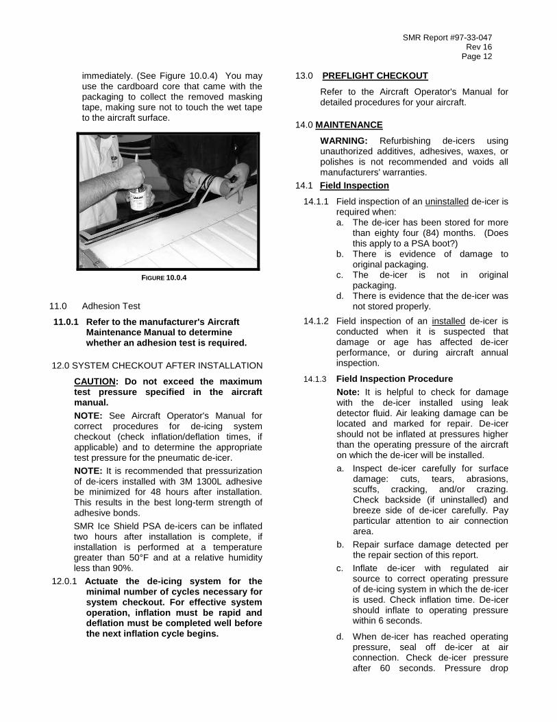
10.0.4 Mix A56B edge sealer in accordance with directions on the can. In the masked area between the tapes, apply a smooth, continuous brush coat of the approved conductive edge sealer to the surface, using a 1.5” brush. Remove the masking tape immediately after applying the sealer and before the sealer dries. This operation will go more smoothly if one person applies the sealer while another removes the tape
SMR Report #97-33-047 Rev 16
Page 12
immediately. (See Figure 10.0.4) You may use the cardboard core that came with the packaging to collect the removed masking tape, making sure not to touch the wet tape to the aircraft surface.
FIGURE 10.0.4
11.0 Adhesion Test
11.0.1 Refer to the manufacturer's Aircraft Maintenance Manual to determine whether an adhesion test is required.
12.0 SYSTEM CHECKOUT AFTER INSTALLATION
CAUTION: Do not exceed the maximum test pressure specified in the aircraft manual.
NOTE: See Aircraft Operator's Manual for correct procedures for de-icing system checkout (check inflation/deflation times, if applicable) and to determine the appropriate test pressure for the pneumatic de-icer.
NOTE: It is recommended that pressurization of de-icers installed with 3M 1300L adhesive be minimized for 48 hours after installation. This results in the best long-term strength of adhesive bonds.
SMR Ice Shield PSA de-icers can be inflated two hours after installation is complete, if installation is performed at a temperature greater than 50°F and at a relative humidity less than 90%.
12.0.1 Actuate the de-icing system for the minimal number of cycles necessary for system checkout. For effective system operation, inflation must be rapid and deflation must be completed well before the next inflation cycle begins.
13.0 PREFLIGHT CHECKOUT
Refer to the Aircraft Operator's Manual for detailed procedures for your aircraft.
14.0 MAINTENANCE
WARNING: Refurbishing de-icers using unauthorized additives, adhesives, waxes, or polishes is not recommended and voids all manufacturers' warranties.
14.1 Field Inspection
14.1.1 Field inspection of an uninstalled de-icer is required when:
a. The de-icer has been stored for more than eighty four (84) months. (Does this apply to a PSA boot?)
b. There is evidence of damage to original packaging.
c. The de-icer is not in original packaging.
d. There is evidence that the de-icer was not stored properly.
14.1.2 Field inspection of an installed de-icer is conducted when it is suspected that damage or age has affected de-icer performance, or during aircraft annual inspection.
14.1.3 Field Inspection Procedure
Note: It is helpful to check for damage with the de-icer installed using leak detector fluid. Air leaking damage can be located and marked for repair. De-icer should not be inflated at pressures higher than the operating pressure of the aircraft on which the de-icer will be installed.
a. Inspect de-icer carefully for surface damage: cuts, tears, abrasions, scuffs, cracking, and/or crazing. Check backside (if uninstalled) and breeze side of de-icer carefully. Pay particular attention to air connection area.
b. Repair surface damage detected per the repair section of this report.
c. Inflate de-icer with regulated air source to correct operating pressure of de-icing system in which the de-icer is used. Check inflation time. De-icer should inflate to operating pressure within 6 seconds.
d. When de-icer has reached operating pressure, seal off de-icer at air connection. Check de-icer pressure after 60 seconds. Pressure drop

SMR Report #97-33-047 Rev 16
Page 13
should not exceed 3 psi for de-icers with system operating pressure of 14 psi or higher.
e. Allow de-icer to deflate naturally with no vacuum applied. Deflation time should not exceed 22 seconds. (Check Aircraft Manual to confirm deflation time, as there are a few deviations to this criterion.) When de-icer is deflated, check for pockets of trapped air in tubes.
f. If de-icer does not pass these tests, check again for damage and perform appropriate repairs and retest. If de-icer still does not meet these criteria, the de-icer should be replaced (if installed) or scrapped. If de-icer passes all tests, its usability is on condition and the decision to install is at user’s discretion.
14.2 Cleaning
NOTE: Petroleum derivatives can be harmful to de-icers. Do not use them as cleaning agents for pneumatic de-icers.
14.2.1 Clean pneumatic de-icers, when needed, with a soap and water solution. Rinse with clean water. Do not use hot water. Water should be comfortable to the bare hand. If cleaning compound MIL-C-25769 is used to clean the airplane, thoroughly rinse the pneumatic de-icer with clean water.
14.3 Pneumatic De-Icer Care
14.3.1 Do not rest ladders or work stands against pneumatic de-icers. Wrap padding around those portions of work stands that could come into contact with installed pneumatic de-icers.
14.3.2 Do not drag refueling or other servicing hoses over the pneumatic de-icers. Use suitable padding for protection. Do not walk, lay tools or sharp objects on the pneumatic de-icers.
14.4 Ice Shield Plus Application
Ice Shield Plus is a silicone based liquid coating that reduces ice adhesion to pneumatic de-icer surfaces. This reduced ice adhesion increases the efficiency and performance of the working de-icer.
NOTE: A heavy application will produce a tacky surface and hinder the effectiveness of
Ice Shield Plus. Follow Manufacturers instructions on container.
Clean the de-icer surface with mild soap and water. Rinse with clean water and allow drying.
Apply Ice Shield Plus by spraying a light coat on the surface and wipe with a clean cloth in smooth, lengthwise strokes to insure a consistent coat over the entire surface.
14.5 Pneumatic De-Icer Repair
Note: Refer to Aircraft Maintenance Manual for specific instructions to repair limits.
Ice Shield brand pneumatic de-icers may be repaired using De-icer Repair Kit PN 2MA1419-01 (See Accessories, Section 13.3).
14.6 Repair Limits
The Ice Shield Repair Kit is designed for repairs to all Ice Shield pneumatic de-icers. Repairs are confirmed by a functional test per the Field Inspection Procedure section 10.1.3.
Patch repairs are not recommended for the following damage:
1. Cut, tear or rupture exceeding ¾” in length.
2. Cut, tear or rupture within 1/8” of a stitch line (on sewn de-icers).
3. Cut, tear or rupture that extends into the fabric stitch line will require immediate de-icer replacement.
4. Patch repairs are permissible for damage as described in (1) and (2) above temporarily, until a replacement can be scheduled, provided the part meets functional test criteria per Field Inspection Procedure section 10.1.3.
Recommended limits for application of patches for maximum operating efficiency of a pneumatic de-icer.
Three (3) small patches (1 ¼” x 2 ½”) per any 12-inch square area.
Two (2) medium patches (2 ½” x 5”) per any 12-inch square area.
One (1) large patch (5” x 10”) per any 12-inch square area.
14.7 Material List
Materials in kit PN 2MA1419-01:
Part Number Description
2MA1419-07 ½ pint Primer #94
4MA1929-3 30 pcs. (Pkg.) sm. patch (1 ¼” x 2 ½”)
4MA1929-2 30 pcs. (Pkg.) med. patch (2 ½” x 5”)
4MA1929-1 10 pcs. (Pkg.) large patch (5” x 10”)
2MA1419-06 3 pcs. (Pkg.) emery cloth, coarse grit
2MA1913-01 1 ea. Patch Template/Sanding Shield

SMR Report #97-33-047 Rev 16
Page 14
Required materials not supplied in kit.
(Equivalent substitutes permitted)
Description Vendor/Part Number
2 “Wide Roller SMR P/N 2MA1414-02
Bristle Brushes, ½” SMR P/N 2MA1414-10
Detergent Commercially available
Lint-free cloths Commercially available
Cleaning solvent,
(Toluene or Alcohol) Commercially available
“Zip-loc” bag, plastic,
(One-gallon size) Commercially available
14.8 Repair Instructions
CAUTION: Patches have one-way stretch across the width of the patch so that the patch will stretch as the de-icer is inflated. The patch must be installed with the length parallel to the de-icer tubes. Failure to do so may result in the patch lifting when the de-icer is inflated.
CAUTION: Patch adhesive is temperature sensitive. For best results if temperature is less than 50 degrees F, warm de-icer surface prior to applying primer and warm installed patch while drying. To warm, hold a plastic bag filled with hot water on de-icer surface installed patch. Patch may not adhere if surface and installed patch are not warmed.
NOTE: Patch must extend ½-inch minimum distance beyond the damaged area and may be trimmed for small areas.
14.8.1 Clean de-icer surface to be patched with hot water and detergent using a clean cloth to remove dirt, grease and silicone coatings.
14.8.2 Sand de-icer surface with medium grit emery cloth or equivalent. Use patch template to outline damaged area and also use as a shield during sanding.
14.8.3 Wipe de-icer surface with a clean cloth dampened with cleaning solvent (Toluene or Alcohol) and allow drying.
14.8.4 Apply one coat of primer to de-icer surface and allow drying to touch (5 - 10 minutes).
14.8.5 Remove paper backing from patch and center patch over outlined primer area on the de-icer surface. Roll patch firmly with rubber roller.
14.8.6 Allow 30 minutes cure time before inflating de-icer.
14.9 Patch Replacement
14.9.1 Remove old patch from de-icer surface.
14.9.2 Remove residual adhesive with alcohol and fine/medium grade buffing pad.
14.9.3 Apply new patch per instructions in Section 10.8.
15.0 TROUBLESHOOTING
Refer to the aircraft manufacturer’s maintenance manual for specific information on probable malfunctions and remedial actions to be taken.
16.0 STORAGE
The life of an uninstalled pneumatic de-icer may be decreased by improper storage conditions. The following conditions should be maintained for the best service life. Where the ideal conditions are not attainable, attempt to approach them as closely as possible.
16.1 Packaging
Each pneumatic de-icer is sealed in an airtight polyethylene bag and boxed prior to shipment. Store the pneumatic de-icer in its original sealed packaging in an area free from sunlight, harmful fumes and excessive dust. (See Figure 16.1)
FIGURE 16.1
16.2 Harmful Substances
Do not store petroleum products, solvents, hydraulic fluids or other substances that may be injurious to rubber in close proximity to pneumatic de-icers.
16.3 Ozone
NEVER store pneumatic de-icers near electric motors or other sources of ozone.

SMR Report #97-33-047 Rev 16
Page 15
16.4 Temperature
Store in a space protected from extreme temperatures. Ideal storage temperature is between 40° and 80°F (5 to 27°C).
16.5 Stresses
Never store pneumatic de-icers under mechanical stresses that could cause kinking, wrinkling, or creasing. Never stack anything on a rolled-up pneumatic de-icer.
17.0 ACCESSORIES
17.1 Installation Kit
2MA1414-01
FIGURE 17.1
17.2 Ice Shield Plus
SMRPLUS-22, Spray Bottle
SMRPLUS-32, Container
FIGURE 17.3
17.4 De-Icer Repair Kit
2MA1419-01, Universal Pneumatic De-icer Repair Kit
FIGURE 17.4
17.5 Adhesive Kits Contents
FIGURE 17.5
Kit, Adhesive PN 2MA1425-02
Description Qty
1300L Adhesive 1ea Qt
SMR-A56B Conductive Edge Cement 1 ea ½ pt
Brush, Bristle 3 in. wide 2 ea
Brush, Bristle 1 in. wide 1 ea
Stick, Stir 2 ea
Swab, Sewn 2 ea

SMR Report #97-33-047 Rev 16
Page 16
17.6 PSA Primer Kit Contents
FIGURE 17.6
Kit, Adhesive PN 2MA1778-02
Description Qty
3M Primer 94 1ea ½ pt
SMR-A56B Conductive Edge Cement 1 ea ½ pt
Brush, Foam 3 in. wide 2 ea
Brush, Bristle 1 in. wide 1 ea
Swab, Sewn 2 ea

SMR Report #97-33-047 Rev 16
Page 17
18.0 WARRANTY
All Ice Shield Pneumatic De-Icers are warranted to be free from material and workmanship defects for twenty-four (24) months or 3,000 flight hours from the date of sale to the end user, whichever first occurs, but not beyond eighty-four months from date of manufacture (60 month storage).
All Ice ShieldTM
Propeller De-Icers are warranted to be free from material and workmanship defects for eighteen (18) months or 2,000 flight hours from date of sale to the end user, whichever first occurs.
The foregoing warranties are exclusive and are accepted by the buyer in lieu of any and all other warranties, expressed or implied, including without limitation, the implied warranties of merchantability and fitness for a particular purpose. Buyers sole remedy in the event of a breach of the foregoing warranties is the repair or replacement of the affected product by SMR Acquisitions, LLC dba SMR Technologies, Inc. (SMR) upon return of the product, transportation charges prepaid to (SMR) and after, a charge to buyer for use of the product prior to its return. Buyer agrees that in no event will (SMR) liability under any theory of contract, negligence, strict liability, other tort or otherwise, exceed buyer’s net purchase price, nor will (SMR) be liable for any special, incidental, consequential, or exemplary damages.
(SMR) assumes no liability whatsoever, whether contractual, warranty, tort or otherwise, for any federal aviation administration sanctions, product malfunctions, property damage, personal injuries, or similar incidents occurring after any substitution of parts not manufactured by (SMR) or any alteration of (SMR) manufactured parts not authorized by (SMR) manuals or other written procedures issued by (SMR).
The foregoing warranties will continue in effect for so long as the product is serviced and maintained in accordance with (SMR) instructions and with genuine (SMR) manufactured replacement parts. These warranties may not be altered or amended except by a written instrument signed by buyer and a duly authorized officer of (SMR).
18.1 Repairs and Returns
To return any parts for warranty consideration, you must first request a Return Goods (RG Authorization) number. To receive the number, simply contact a Sales & Service Representative (SSR) at:
Toll Free: 1.800.767.6899
Phone: 1.304.846.6636
Fax: 1.304.846.6268
The SSR will provide you with a return address. Please do not ship any returned parts without the RG number as this number allows SMR to track the part and the resolution of the claim.
The warranty is limited to returns for the following reasons:
1. Wrong items shipped
2. Wrong items ordered
3. Any return for credit
4. Items damaged in shipment
5. Warranted defects
Effective Date: July 1, 1998
Revised November 5, 2002

SMR Report #97-33-047 Rev 16
Page 18
19.0 END ITEM USER LETTER
SMR Technologies, Inc. 93 Nettie Fenwick Rd. Fenwick, West Virginia 26202-4000 Phone Number: 1-800-767-6899
To: End Item User/Installer From: SMR Technologies Subject: End Item Use Authorization Letter SMR Technologies hereby authorizes any end item user/installer to install this product under the issued Supplemental Type Certificate (STC). Should an actual copy of the STC be needed, please contact our facility by calling the number listed above or visit our web-site at www.iceshield.com.