ferroresonance in power systems...experimental and modelling studies that clearly indicates the...
TRANSCRIPT
FERRORESONANCE IN POWER SYSTEMSREPORT 2017:457
NUCLEAR
GRID INTERFERENCE ON NUCLEAR POWER PLANT OPERATIONS
NUCLEAR

Ferroresonance in Power Systems Literature study
GÖRAN ENGDAHL
ISBN 978-91-7673-457-5 | © Energiforsk November 2017
Energiforsk AB | Phone: 08-677 25 30 | E-mail: [email protected] | www.energiforsk.se

FERRORESONANCE IN POWER SYSTEMS
3
Foreword
This report was commissioned by the steering group of the Energiforsk Grid Interference on Nuclear power plant Operations (GINO) program, to learn more about the ferroresonance phenomena. An important part of the GINO program is to gain knowledge of different factors and phenomena that might challenge the safety of a nuclear power plant under certain circumstances.
The report is written by professor Göran Engdahl senior professor from the Royal Insititute of Technology, KTH, in Stockholm. The GINO program is financed by The Swedish Radiation Safety Authority, Vattenfall, Uniper/Sydkraft Nuclear, Fortum, Skellefteå Kraft and Karlstads Energi.
These are the results and conclusions of a project, which is part of a research programme run by Energiforsk. The author/authors are responsible for the content.
FERRORESONANCE IN POWER SYSTEMS
4
Sammanfattning
I rapporten ges en kort beskrivning av historiken förknippad med termen ferroresonans. Dessutom presenteras den bakomliggande fysikaliska orsaken till ferroresonans som traditionellt betraktas som ett fenomen. Alstringsmekanismen presenteras med ett enkelt exempel som kan reproduceras med hjälp av spänningskälla, en kondensator och en liten luftisolerad enfastransformator.
Allmänna kriterier för uppkomst av ferroresonans presenteras med några praktiska exempel såsom vid användning av spänningstransformatorer i kraftsystem med bristande jordning och/eller dämpning och en distributionstransformator med en öppen fas.
Vidare presenteras en simuleringsmodell av denna distributionstransformator med tillhörande simuleringsresultat. Dessa resultat demonstrerar tydligt att ferroresonans kan uppvisa ett kaotiskt beteende och att den använda simuleringsmodellen måste innehålla en mycket detaljerad representation av transformatorns järnkärna för att kunna prognostisera ferroresonans.
Fortsatt forskning och utveckling avseende både mjuk- och hårdvara för modeller samt beräkningsteknik behövs för att erhålla tillförlitliga verktyg för att kunna förutsäga ferroresonans.
I rapporten ges litteraturanvisningar samt följande exempel på när uppmärksamhet bör riktas mot eventuell förekomst av ferroresonans:
• Lätt belastade transformatorer som arbetar i närvaro av kapacitanser. • Öppna transformatorfaser av både kort och lång varaktighet. • Ej synkroniserad omkoppling av transformatorfaser. • Användning av spänningstransformator utan åtgärder för dämpning. • Förlust av systemjordning, svag jordning eller jordning via ströinduktanser. • Användning av spänningsfördelningkapacitanser i högspänningbrytare. • Användning kondensatorer vid shunt- eller seriekompensering • Användning av shuntreaktorer med mättbara magnetkärnor.
FERRORESONANCE IN POWER SYSTEMS
5
Summary
The report gives a brief description of the history associated with the term ferroresonance. In addition, the underlying physical cause of ferroresonance, which traditionally is regarded as a phenomenon, is presented. The generation mechanism is presented with a simple example that can be reproduced by means of a voltage source, a capacitor and a small air-insulated single-phase transformer,
General criteria of the emergence of ferroresonance are presented with some practical examples such as when using voltage transformers in power systems with inadequate grounding and / or damping and a distribution transformer with an open phase.
Furthermore, a simulation model of this distribution transformer is presented with corresponding simulation results. These results clearly demonstrate that ferroresonance can show chaotic behavior and that the simulation model used must contain a highly detailed representation of the iron core of the transformer in order to be able to forecast ferroresonance.
Continued research and development regarding both soft and hardware for models and computing techniques are needed to obtain reliable tools to predict ferroresonance.
The report provides literature directions as well as the following examples of when attention should be paid to possible occurrence of ferroresonance.
• Lightly loaded transformers operating in presence or capacitance. • Open transformer phases of both short and long duration. • Unsynchronized switching of transformer phases. • Use of voltage transformers without any damping measures. • Loss of system grounding, weak grounding or grounding through stray
inductances. • Use of voltage distribution capacitances in high voltage breakers. • Use of capacitors in shunt and series compensation • Use of shunt reactors with saturable magnetic cores.
FERRORESONANCE IN POWER SYSTEMS
6
List of content
1 Introduction 7 2 Ferroresonance basics 8 3 General criteria of possible ferroresonance in power systems 11 4 Ferroresonance in three phase systems 12
4.1 Practical examples 14 5 Modelling example 16
6 Conclusion 26 7 Recommendations 27 8 Possible future research 28 9 Available literature 29
FERRORESONANCE IN POWER SYSTEMS
7
1 Introduction
Resonance in transformers in power systems first appears in literature 1907 by J. Bethenod[1]. The concept ”ferroresonance” was coined in 1920s by Paul Boucherot[2].
Ferroresonance has traditionally been regarded as a “phenomenon” due to to its unpredictability and lack of understanding.
In the 1940s R. Rudenberg[3] performed the first analytical work on ferroresonance and in the 1950s C. Hayashi[4] did a more comprehensive work on the phenomenon.
After that the work has been divided in two main areas with focus on
1. improving transformer models to predict their behavior, and 2. studies on ferroresonance of transformer installed in power systems.
A deeper understanding of ferroresonance was obtained in the mid 1980s by G. W. Swift[5] and D, C. Jiles[6]. They emphasized that a prerequisite for resonance to occur is the nonlinear and hysteretic behavior of the transformer core.
Researchers as Smith[7], Kieny[8], and Mork[9] have later in the 1990s extended experimental and modelling studies that clearly indicates the chaotic features of the concept “ferroresonance” that renders its unpredictability as what is characteristic in weather, climate, and stock market forecasting, epidemiology etc.
This report comprise a short summary of the state of the art concerning ferroresonance with illustrating examples, recommendations how to avoid it, and literature references for gaining more insight and hints on tentative further research in this field.
FERRORESONANCE IN POWER SYSTEMS
8
2 Ferroresonance basics
Ferroresonance is in principle a series resonance with a capacitor and a nonlinear inductance that involves a saturable magnetizing inductance. The phenomenon preferably occurs in the absence of an appropriate damping. In a power system that inductance typically consists of the magnetizing inductances of power transformers and the series capacitances of occurring capacitances and in the net.
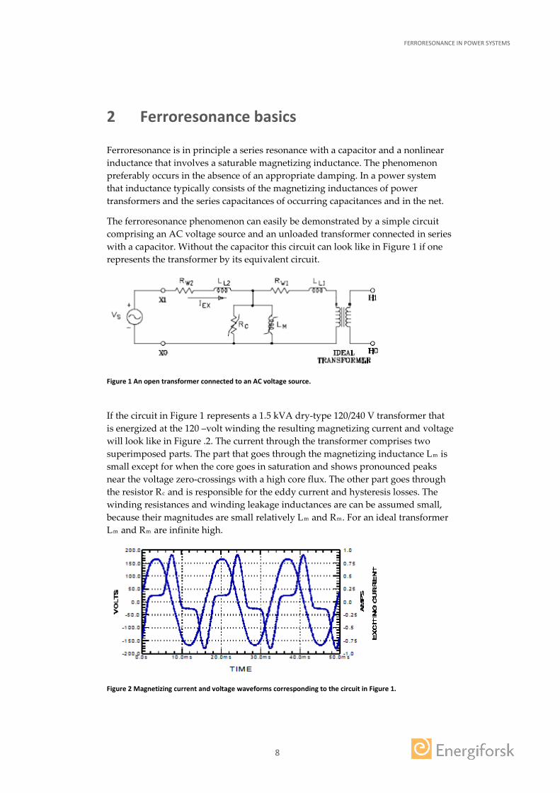
The ferroresonance phenomenon can easily be demonstrated by a simple circuit comprising an AC voltage source and an unloaded transformer connected in series with a capacitor. Without the capacitor this circuit can look like in Figure 1 if one represents the transformer by its equivalent circuit.
Figure 1 An open transformer connected to an AC voltage source.
If the circuit in Figure 1 represents a 1.5 kVA dry-type 120/240 V transformer that is energized at the 120 –volt winding the resulting magnetizing current and voltage will look like in Figure .2. The current through the transformer comprises two superimposed parts. The part that goes through the magnetizing inductance Lm is small except for when the core goes in saturation and shows pronounced peaks near the voltage zero-crossings with a high core flux. The other part goes through the resistor Rc and is responsible for the eddy current and hysteresis losses. The winding resistances and winding leakage inductances are can be assumed small, because their magnitudes are small relatively Lm and Rm. For an ideal transformer Lm and Rm are infinite high.
Figure 2 Magnetizing current and voltage waveforms corresponding to the circuit in Figure 1.
FERRORESONANCE IN POWER SYSTEMS
9
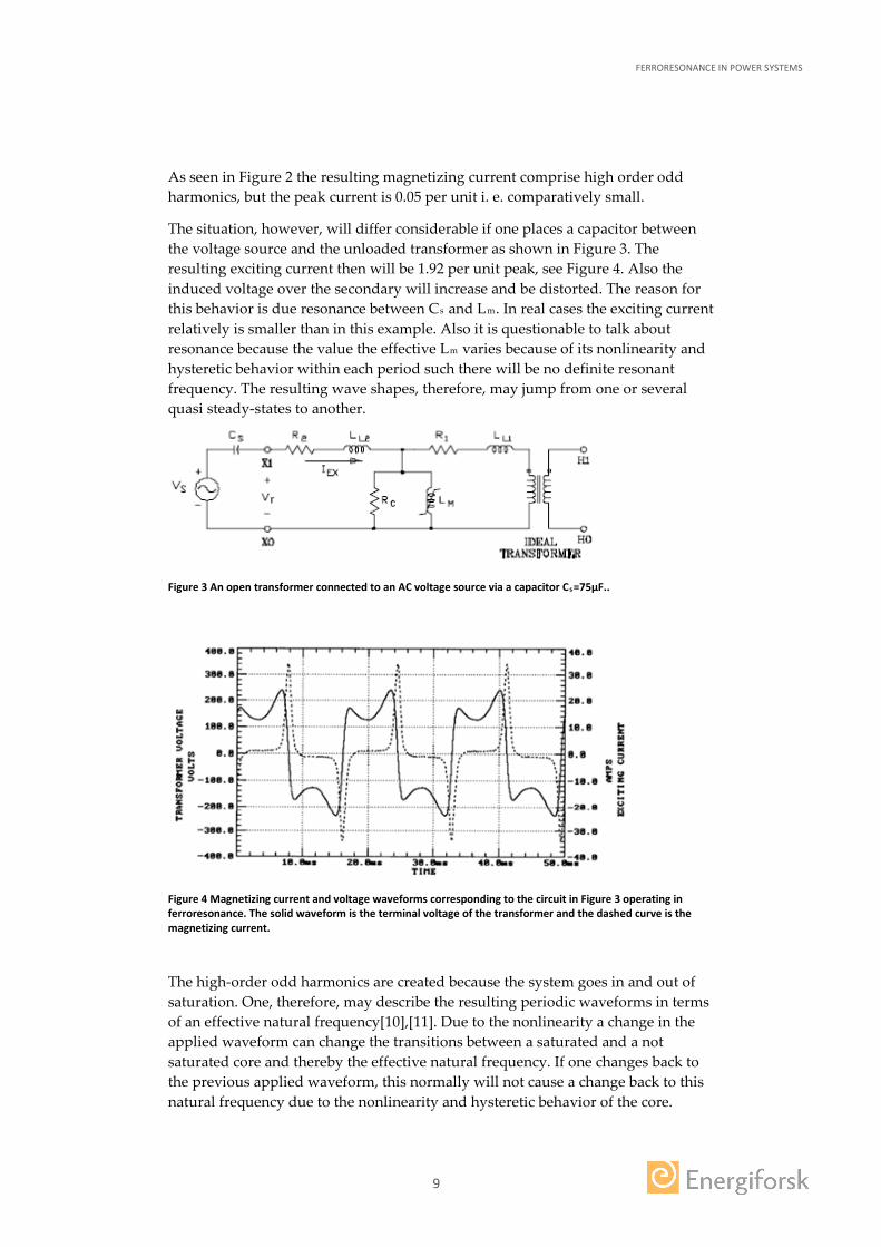
As seen in Figure 2 the resulting magnetizing current comprise high order odd harmonics, but the peak current is 0.05 per unit i. e. comparatively small.
The situation, however, will differ considerable if one places a capacitor between the voltage source and the unloaded transformer as shown in Figure 3. The resulting exciting current then will be 1.92 per unit peak, see Figure 4. Also the induced voltage over the secondary will increase and be distorted. The reason for this behavior is due resonance between Cs and Lm. In real cases the exciting current relatively is smaller than in this example. Also it is questionable to talk about resonance because the value the effective Lm varies because of its nonlinearity and hysteretic behavior within each period such there will be no definite resonant frequency. The resulting wave shapes, therefore, may jump from one or several quasi steady-states to another.
Figure 3 An open transformer connected to an AC voltage source via a capacitor Cs=75µF..
Figure 4 Magnetizing current and voltage waveforms corresponding to the circuit in Figure 3 operating in ferroresonance. The solid waveform is the terminal voltage of the transformer and the dashed curve is the magnetizing current.
The high-order odd harmonics are created because the system goes in and out of saturation. One, therefore, may describe the resulting periodic waveforms in terms of an effective natural frequency[10],[11]. Due to the nonlinearity a change in the applied waveform can change the transitions between a saturated and a not saturated core and thereby the effective natural frequency. If one changes back to the previous applied waveform, this normally will not cause a change back to this natural frequency due to the nonlinearity and hysteretic behavior of the core.
FERRORESONANCE IN POWER SYSTEMS
10
Voltage transients can also trigger a transition from one natural frequency mode to another[3].
With a modern vocabulary, these jumps are referred to as bifurcations that can be understood and described by applying the theories of nonlinear dynamics and chaos [9],[10],[12].
If one introduces damping in the system the ferroresonant phenomenon will be attenuated. In a real case there are always damping present in form of a resistive source impedance, transformer losses and for high voltage systems corona losses. The dominant damping normally is due to the load applied to the secondary of the transformer.
Ferroresonance can lead to excess heating of the transformer due to increased peak currents and high core fluxes. High temperatures inside the transformer may weaken the insulation and cause a failure due the increased electrical stresses. In extremely high voltage systems the first cycles of the ferroresonance can result in an insulation coordination problem involving frequencies higher than the operating frequency of the system.

FERRORESONANCE IN POWER SYSTEMS
11
3 General criteria of possible ferroresonance in power systems
Based on the general features of ferroresonance some basic criteria for occurrence of ferroresonance can be stated:
• A capacitance in series with the core’s magnetizing inductance, • unloaded or lightly loaded transformer (very rough rule of thumb: below 10-
20% of the rated load), • single-pole switching procedures or interrupting devices in a three-phase
system.
Transformers of any kind may be involved. Some obvious cases are:
• single-phase power transformers and voltage transformers energized through a series capacitance,
• three-phase distribution transformers subject to single-pole switching or interruption,
• shunt reactors with saturable cores.
The involved capacitances can be in the form of actual capacitor banks, or as capacitive coupling. Actual “capacitor banks” are easy to visualize, but capacitive coupling effects can be more difficult to identify. Some examples where ferroresonance may occur are given below.
• Series capacitor for line compensation. • Shunt capacitor banks. • Underground cables. • Capacitive coupling, coupling capacitances between double circuit lines. • Systems grounded only via stray capacitances. • Grading capacitors on circuit breakers. • Generator surge capacitors. • Internal capacitive coupling in transformers.
FERRORESONANCE IN POWER SYSTEMS
12
4 Ferroresonance in three phase systems
Ferroresonance in a three phase system may occur in the applied or induced voltage connected to a capacitance in series with a transformer magnetizing reactance.
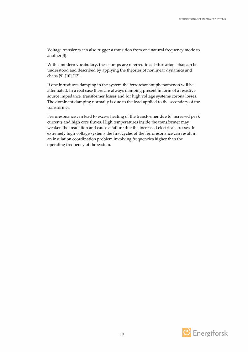
In Figure 5 three examples are given as examples when a single phase is switched in a power system where wye-connected capacitance is paralleled with an unloaded wye-connected transformer. The involved capacitors can be the shunt capacitances of the connecting cables from the source or a shunted capacitor bank. The transformer phases are represented by jXm, because the ferroresonance only involves the magnetizing reactance.
Figure 5 Three examples of ferroresonance in a three phase system.
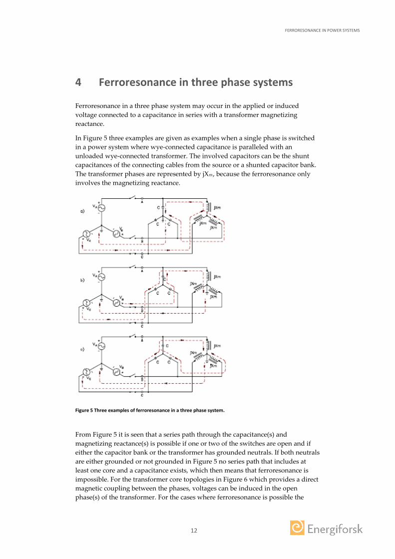
From Figure 5 it is seen that a series path through the capacitance(s) and magnetizing reactance(s) is possible if one or two of the switches are open and if either the capacitor bank or the transformer has grounded neutrals. If both neutrals are either grounded or not grounded in Figure 5 no series path that includes at least one core and a capacitance exists, which then means that ferroresonance is impossible. For the transformer core topologies in Figure 6 which provides a direct magnetic coupling between the phases, voltages can be induced in the open phase(s) of the transformer. For the cases where ferroresonance is possible the
FERRORESONANCE IN POWER SYSTEMS
13
above holds for any configuration of the transformer core and even if each phase is supplied as stand-alone units.
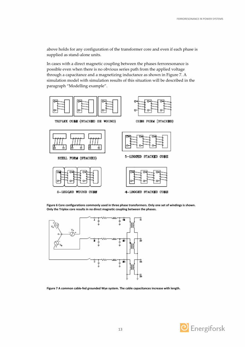
In cases with a direct magnetic coupling between the phases ferroresonance is possible even when there is no obvious series path from the applied voltage through a capacitance and a magnetizing inductance as shown in Figure 7. A simulation model with simulation results of this situation will be described in the paragraph “Modelling example”.
Figure 6 Core configurations commonly used in three phase transformers. Only one set of windings is shown. Only the Triplex core results in no direct magnetic coupling between the phases.
Figure 7 A common cable-fed grounded Wye system. The cable capacitances increase with length.
FERRORESONANCE IN POWER SYSTEMS
14
4.1 PRACTICAL EXAMPLES
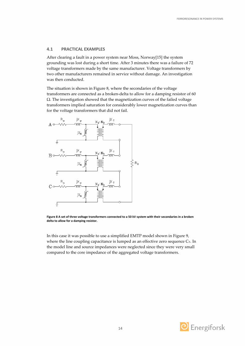
After clearing a fault in a power system near Moss, Norway[15] the system grounding was lost during a short time. After 3 minutes there was a failure of 72 voltage transformers made by the same manufacturer. Voltage transformers by two other manufacturers remained in service without damage. An investigation was then conducted.
The situation is shown in Figure 8, where the secondaries of the voltage transformers are connected as a broken-delta to allow for a damping resistor of 60 Ω. The investigation showed that the magnetization curves of the failed voltage transformers implied saturation for considerably lower magnetization curves than for the voltage transformers that did not fail.
Figure 8 A set of three voltage transformers connected to a 50 kV system with their secondaries in a broken delta to allow for a damping resistor.
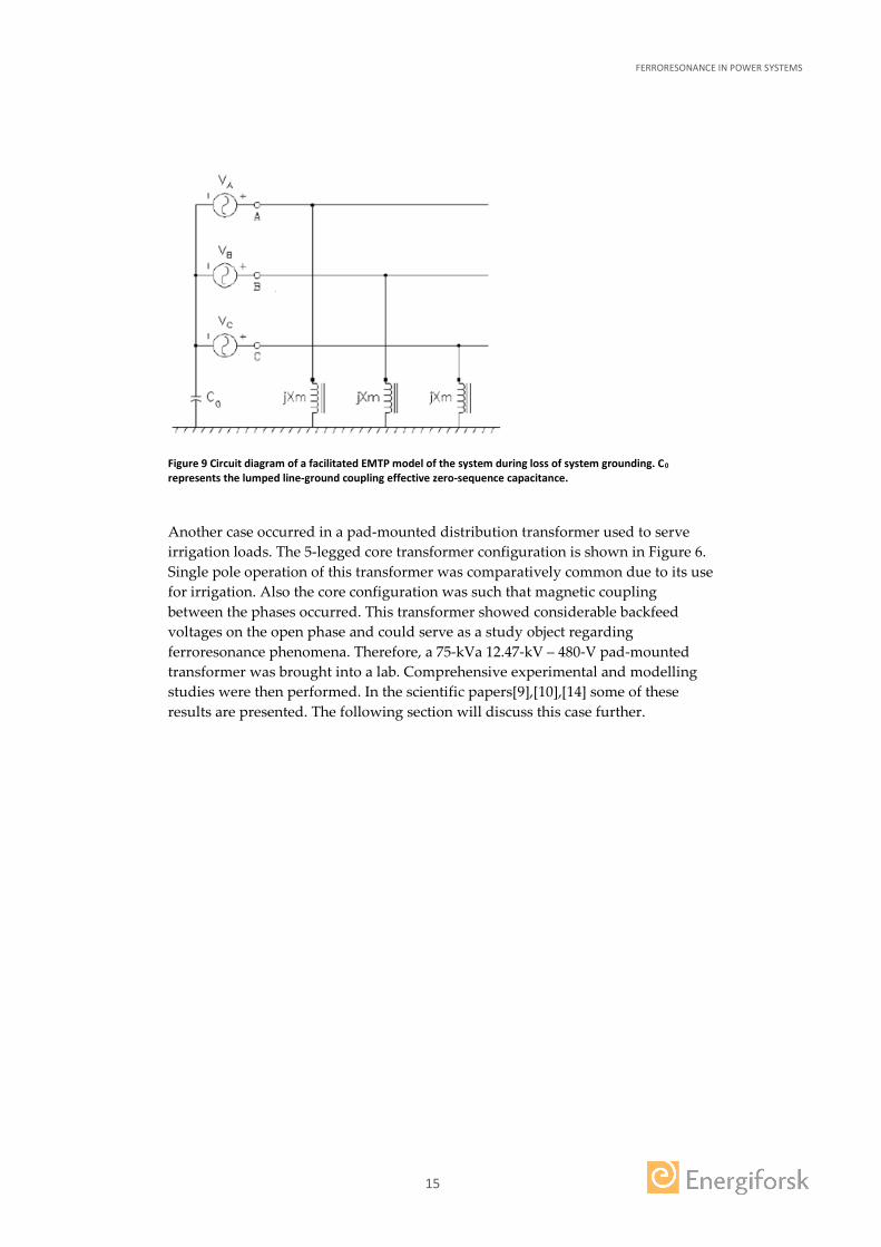
In this case it was possible to use a simplified EMTP model shown in Figure 9, where the line coupling capacitance is lumped as an effective zero sequence C0. In the model line and source impedances were neglected since they were very small compared to the core impedance of the aggregated voltage transformers.
FERRORESONANCE IN POWER SYSTEMS
15
Figure 9 Circuit diagram of a facilitated EMTP model of the system during loss of system grounding. C0 represents the lumped line-ground coupling effective zero-sequence capacitance.
Another case occurred in a pad-mounted distribution transformer used to serve irrigation loads. The 5-legged core transformer configuration is shown in Figure 6. Single pole operation of this transformer was comparatively common due to its use for irrigation. Also the core configuration was such that magnetic coupling between the phases occurred. This transformer showed considerable backfeed voltages on the open phase and could serve as a study object regarding ferroresonance phenomena. Therefore, a 75-kVa 12.47-kV – 480-V pad-mounted transformer was brought into a lab. Comprehensive experimental and modelling studies were then performed. In the scientific papers[9],[10],[14] some of these results are presented. The following section will discuss this case further.
FERRORESONANCE IN POWER SYSTEMS
16
5 Modelling example
A simulation model of the pad-mounted transformer case related to the investigation of occurring ferroresonances mentioned in the previous section was worked out and studied. The electrical circuit diagram of the transformer configuration is shown in Figure 7.
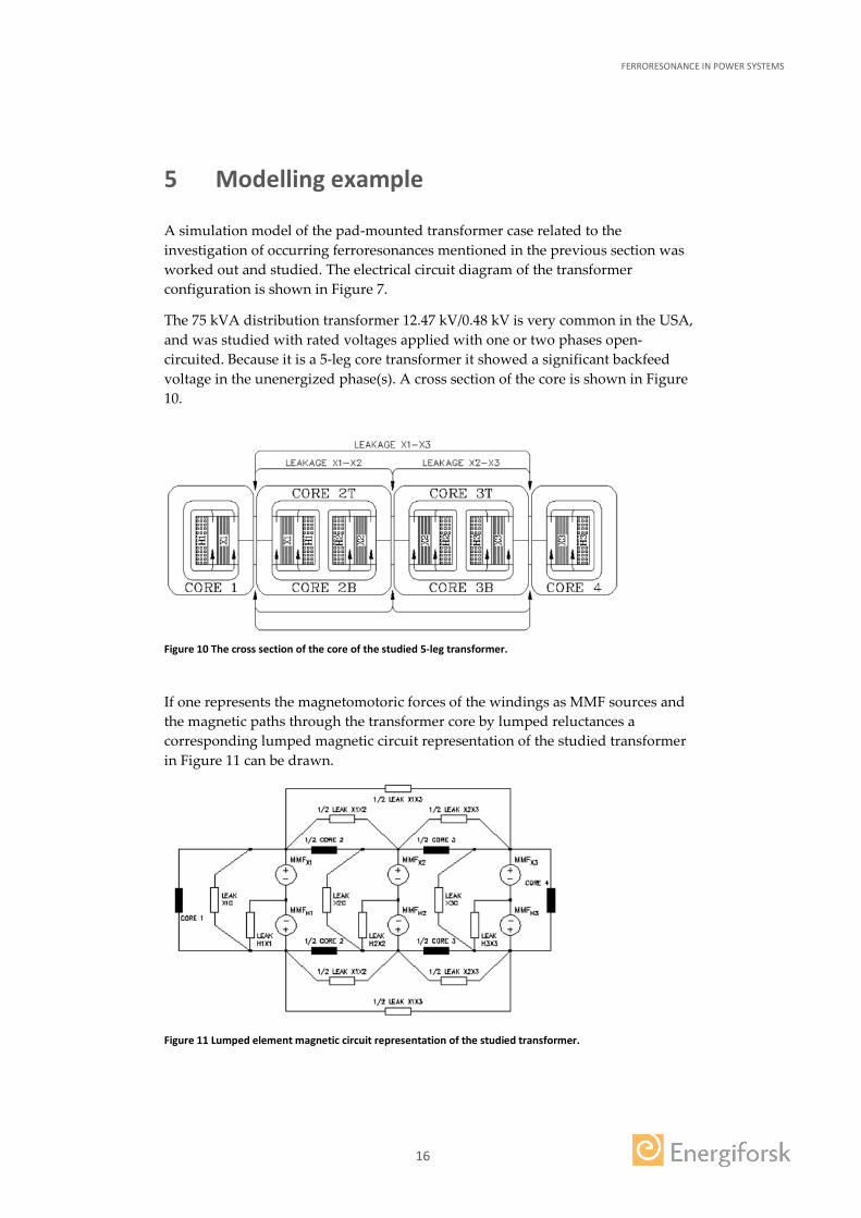
The 75 kVA distribution transformer 12.47 kV/0.48 kV is very common in the USA, and was studied with rated voltages applied with one or two phases open-circuited. Because it is a 5-leg core transformer it showed a significant backfeed voltage in the unenergized phase(s). A cross section of the core is shown in Figure 10.
Figure 10 The cross section of the core of the studied 5-leg transformer.
If one represents the magnetomotoric forces of the windings as MMF sources and the magnetic paths through the transformer core by lumped reluctances a corresponding lumped magnetic circuit representation of the studied transformer in Figure 11 can be drawn.
Figure 11 Lumped element magnetic circuit representation of the studied transformer.
FERRORESONANCE IN POWER SYSTEMS
17
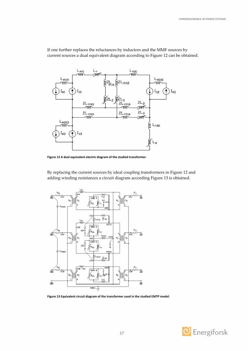
If one further replaces the reluctances by inductors and the MMF sources by current sources a dual equivalent diagram according to Figure 12 can be obtained.
Figure 12 A dual equivalent electric diagram of the studied transformer.
By replacing the current sources by ideal coupling transformers in Figure 12 and adding winding resistances a circuit diagram according Figure 13 is obtained.
Figure 13 Equivalent circuit diagram of the transformer used in the studied EMTP model.
FERRORESONANCE IN POWER SYSTEMS
18
Based on the circuit diagram according to Figure 13 an EMTP model was built. In this model Rc integrators over the cores and eddy current resistors are added to represent the core losses.
During the simulations capacitance(s) were connected to open phase(s) to simulate cable capacitance. The voltage waveforms on open phases were recorded when the capacitance value was varied.
A huge number of simulations were performed. Some basic characteristic of these results are:
• Multiple modes of response is possible for identical system parameters • Steady state responses may be of different period than the period of applied
waveform, or nonperiodic (Chaotic) • Steady state responses may be extremely sensitive to initial conditions or
pertubations • The behavior cannot properly be predicted by linear or reduced order models
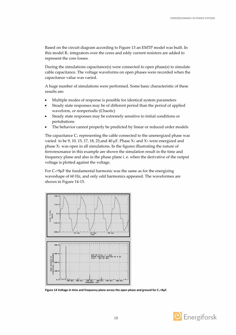
The capacitance Cs representing the cable connected to the unenergized phase was varied to be 9, 10, 15, 17, 18, 25,and 40 µF. Phase X2 and X3 were energized and phase X1 was open in all simulations. In the figures illustrating the nature of ferroresonance in this example are shown the simulation result in the time and frequency plane and also in the phase plane i. e. when the derivative of the output voltage is plotted against the voltage.
For Cs=9µF the fundamental harmonic was the same as for the energizing waveshape of 60 Hz, and only odd harmonics appeared. The waveformes are shown in Figure 14-15.
Figure 14 Voltage in time and frequency plane across the open phase and ground for Cs=9µF.
FERRORESONANCE IN POWER SYSTEMS
19
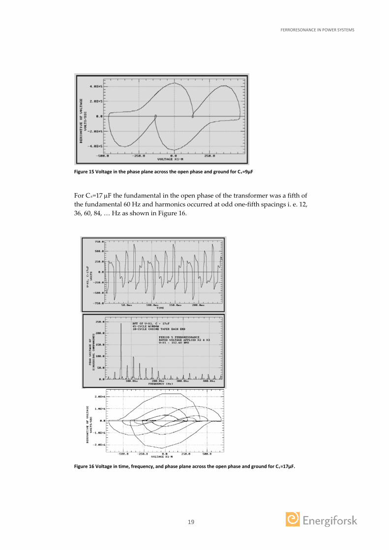
Figure 15 Voltage in the phase plane across the open phase and ground for Cs=9µF
For Cs=17 µF the fundamental in the open phase of the transformer was a fifth of the fundamental 60 Hz and harmonics occurred at odd one-fifth spacings i. e. 12, 36, 60, 84, … Hz as shown in Figure 16.
Figure 16 Voltage in time, frequency, and phase plane across the open phase and ground for Cs=17µF.
FERRORESONANCE IN POWER SYSTEMS
20
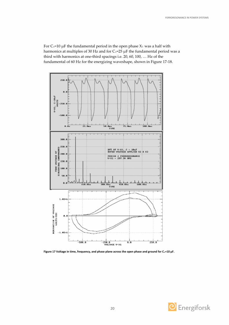
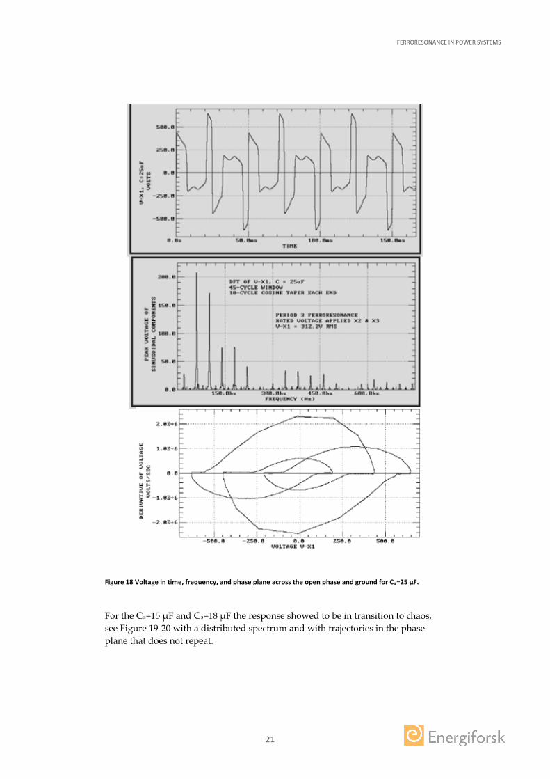
For Cs=10 µF the fundamental period in the open phase X1 was a half with harmonics at multiples of 30 Hz and for Cs=25 µF the fundamental period was a third with harmonics at one-third spacings i.e. 20, 60, 100, … Hz of the fundamental of 60 Hz for the energizing waveshape, shown in Figure 17-18.
Figure 17 Voltage in time, frequency, and phase plane across the open phase and ground for Cs=10 µF.
FERRORESONANCE IN POWER SYSTEMS
21
Figure 18 Voltage in time, frequency, and phase plane across the open phase and ground for Cs=25 µF.
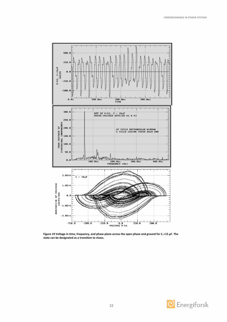
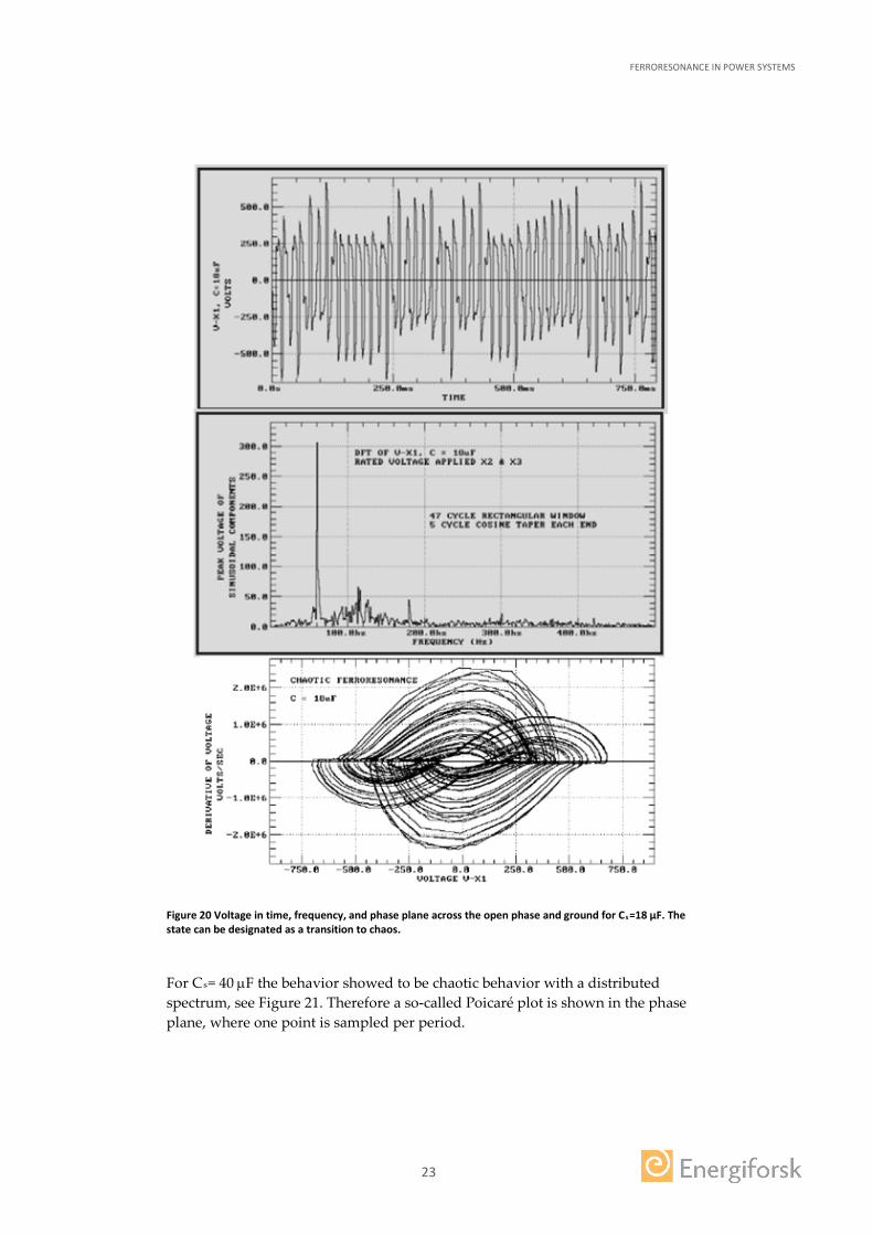
For the Cs=15 µF and Cs=18 µF the response showed to be in transition to chaos, see Figure 19-20 with a distributed spectrum and with trajectories in the phase plane that does not repeat.
FERRORESONANCE IN POWER SYSTEMS
22
Figure 19 Voltage in time, frequency, and phase plane across the open phase and ground for Cs=15 µF. The state can be designated as a transition to chaos.
FERRORESONANCE IN POWER SYSTEMS
23
Figure 20 Voltage in time, frequency, and phase plane across the open phase and ground for Cs=18 µF. The state can be designated as a transition to chaos.
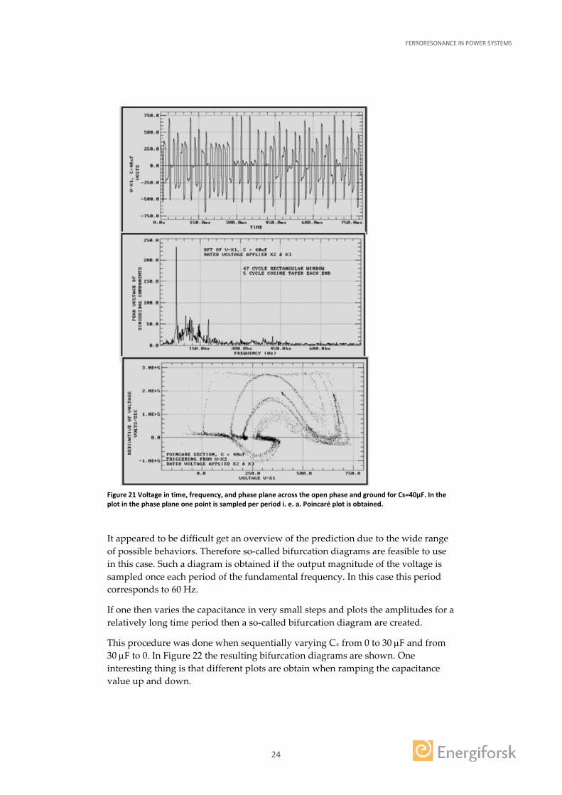
For Cs= 40 µF the behavior showed to be chaotic behavior with a distributed spectrum, see Figure 21. Therefore a so-called Poicaré plot is shown in the phase plane, where one point is sampled per period.
FERRORESONANCE IN POWER SYSTEMS
24
Figure 21 Voltage in time, frequency, and phase plane across the open phase and ground for Cs=40µF. In the plot in the phase plane one point is sampled per period i. e. a. Poincaré plot is obtained.
It appeared to be difficult get an overview of the prediction due to the wide range of possible behaviors. Therefore so-called bifurcation diagrams are feasible to use in this case. Such a diagram is obtained if the output magnitude of the voltage is sampled once each period of the fundamental frequency. In this case this period corresponds to 60 Hz.
If one then varies the capacitance in very small steps and plots the amplitudes for a relatively long time period then a so-called bifurcation diagram are created.
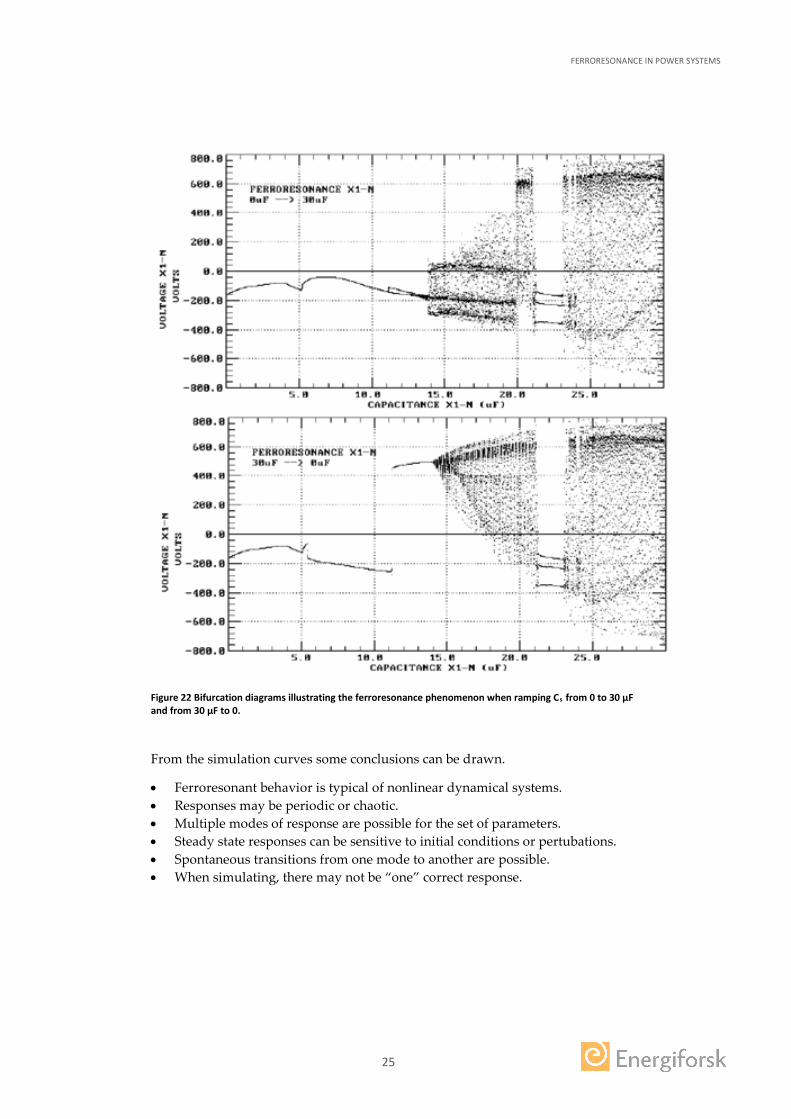
This procedure was done when sequentially varying Cs from 0 to 30 µF and from 30 µF to 0. In Figure 22 the resulting bifurcation diagrams are shown. One interesting thing is that different plots are obtain when ramping the capacitance value up and down.
FERRORESONANCE IN POWER SYSTEMS
25
Figure 22 Bifurcation diagrams illustrating the ferroresonance phenomenon when ramping Cs from 0 to 30 µF and from 30 µF to 0.
From the simulation curves some conclusions can be drawn.
• Ferroresonant behavior is typical of nonlinear dynamical systems. • Responses may be periodic or chaotic. • Multiple modes of response are possible for the set of parameters. • Steady state responses can be sensitive to initial conditions or pertubations. • Spontaneous transitions from one mode to another are possible. • When simulating, there may not be “one” correct response.
FERRORESONANCE IN POWER SYSTEMS
26
6 Conclusion
Experience from measurements on field installations and in the laboratory together with simulations show clearly in which situations ferroresonance may occur.
To exactly forecast ferroresonance in specific situations is very intricate, because the phenomenon shows a chaotic behavior. This feature is caused by the nonlinear and hysteretic properties of the involved transformer core. The nature of possible ferroresonances depends on the structural build-up the transformer. Triplex 3-phase transformers with separate magnetic circuits are very rarely involved in ferroresonances. The magnetic coupling between the phases in the transformer is one key factor regarding occurring ferroresonances. This means that very detailed transformer models are required in a simulation model that can predict ferroresonance with some precision.
The other prerequisite for ferroresonance to occur is that there must be a capacitance in series with the transformer magnetizing inductance. This capacitance does not need to be a discrete capacitor unit. In many cases it can be the lumped capacitance of a connected cable. The capacitance can also be internal stray capacitances occurring in the actual installation. The numerical values of the involved capacitance can be considerably less than 1 µF. This holds preferably for voltage transformers in combination with high voltages, because the magnetizing inductance can be extremely high, in the order Henrys. Because of the high voltage, the oscillating energy can be harmful.
An idle or lightly loaded transformer also constitutes a risk factor, because the damping of the system then is comparatively low.
FERRORESONANCE IN POWER SYSTEMS
27
7 Recommendations
Based on the conclusions of this study the following guidelines can be stated regarding how to prevent the ferroresonance phenomenon.
Reduce the nonlinear feature of the involved inductance. For a power transformer this means that on should choose a transformer with an increased over excitation capability such that it can operate within its magnetic core more linear region.
When capacitors are connected to linear inductances undertake measures to reduce their effective series capacitances. Even a small reduction is favorable, because a lower capacitance implies less resonant energy.
Avoid series electric connection between capacitances and nonlinear inductances. This can for example be done by grounding such that loops comprising capacitive elements and nonlinear inductances are avoided and/or such that the effects of stray capacitances are reduced
When there is a series connection between capacitive elements and a nonlinear inductance assure that there will be a damping resistor in all such closed circuits.
In many situations it is not possible to follow the stated recommendations. In these cases one should be aware of possible ferroresonance phenomena.
Some examples of situations, where one then should be aware of are:
• Lightly loaded transformers operating in presence of capacitances • Open phases – both of short and long duration • Unsynchronized switching of transformer phases. • Use of voltage transformer without measures to guarantee damping • Loss of system grounding or weak grounding or grounding via stray
inductances • Use of capacitors in shunt and series compensation • Use of grading capacitors on circuit breakers • Use of shunt reactors with a saturable cores
FERRORESONANCE IN POWER SYSTEMS
28
8 Possible future research
The key to create a simulation model capable of an accurate prediction of ferroresonance is to accurately model the involved transformer with a detailed representation of its core topology with appropriate models of the nonlinearity and hysteresis of the core material.
Such models must be possible to run extensively to explore the possible ferroresonances for the whole definition area of involved parameters as occurring capacitances etc. This means that both software and hardware for such simulations then should be developed further.
A spin-off of such research will also result in an improvement of the tools to understand and design transformer with more efficient use core and winding material i. e. more compact, and efficient transformer designs.
FERRORESONANCE IN POWER SYSTEMS
29
9 Available literature
Here are some literature references. The list is not complete, but comprises among others the information including figures presented in this literature study.
1. J. Bethenod, "Sur le Transformateur et Résonance",L'Eclairae Electrique, pp. 289-296, November 30, 1907.
2. P. Boucherot, "Existence de Deux Régimes en Ferro-résonance",R.G.E., pp. 827-828, December 10, 1920.
3. R. Rudenberg, Transient Performance of Electric Power Systems, McGraw-Hill Book Company, New York, NY, chapter 48, copyright 1950.
4. C. Hayashi, Nonlinear Oscillations in Physical Systems, McGraw-Hill Book Company, New York, NY, copyright 1964
5. G.W. Swift, "Power Transformer Core Behavior Under Transient Conditions," IEEE Trans. PAS, vol. PAS-90, no. 5, pp. 2206-2209, Sep/Oct 1971.
6. D.C. Jiles and D.L. Atherton, "Theory of Ferromagnetic Hysteresis," Elsevier Science Publishers B.V., Journal of Magnetism and Magnetic Materials, vol. 61. pp. 48-60, January21, 1986.
7. D.R. Smith, S.R. Swanson and J.D. Borst, "Overvoltages with Remotely-Switched Cable-Fed Grounded Wye-Wye Transformers", IEEE Trans. PAS, vol. PAS-94, no. 5, pp. 1843-1853, Sep/Oct 1975.
8. Kieny, "Application of Bifurcation Theory in Studying and Understanding the Global Behavior of a Resonant Electric Power Circuit," IEEE PES Summer Meeting, SM 265-9 PWRD, July 1990.
9. B.A. Mork and D.L. Stuehm, "Application of Nonlinear Dynamics and Chaos to Ferroresonance in Distribution Systems,” IEEE Trans. Power Systems, vol. 9, no. 2, pp. 1009-1017, April 1994.
10. B.A. Mork, Ferroresonance and Chaos - Observation and Simulation of Ferroresonance in a Five-Legged Core Distribution Transformer, Ph.D. Dissertation, North Dakota State University, May 1992. Publication No. 9227588, UMI Publishing Services, Ann Arbor, MI, 48106, (800) 521-0600.
11. B.A. Mork, Ferroresonant Modeling Using EMTP, MS Thesis, North Dakota State University, September 1981.
12. J. Gleick, Chaos: Making a New Science, Viking, New York, NY, copyright 1987 13. J.M.T. Thompson, and H.B. Stewart, Nonlinear Dynamics and Chaos -
Geometrical Methods for Engineers and Scientists, John Wiley and Sons, New York, NY, (Reprinted October 1987), copyright 1986.
14. B. A. Mork, ”Five-Legged Wound-Core Transformer Model: Derivation, Parameters, Impelementation, and Evaluation”, IEEE Trans. Power Delivery, vol. 14, no 4, pp. 1519-1526, October 1999.
15. T. Henriksen and O. Rorvik, ”Ferroresonance i 50 –kV Nett til Hafslund” (in Norwegian), Energiforsyningens Forskningsinstitutt A/s, Trondheim, Norway, ISBN 82-594-0229-7, EFI TR 3779. Dec 19, 1990.
16. R.H. Hopkinson, "Ferroresonance During Single-Phase Switching of 3-Phase Distribution Transformer Banks", IEEE Trans. PAS, vol. PAS-84, no. 4, pp. 289-293, April 1965.
17. R.A. Walling, K.D. Barker, T.M. Compton, and L.E. Zimmerman, "Ferroresonant Overvoltages in Grounded Wye- Wye Padmount
FERRORESONANCE IN POWER SYSTEMS
30
Transformers with Low-Loss Silicon-Steel Cores", IEEE Trans. Power Delivery, vol. 8, no. 3, pp. 1647-1660, July, 1993.
18. D. A. N. Jacobson, Field Testing, Modelling and Analysis of Ferroresonance in a High Voltage Power System, PhD Disseration, Department of Electrical and Cornputer Engineering The University of Manitoba The University of Manitoba Winnipeg, Manitoba, Canada, 2000

FERRORESONANCE IN POWER SYSTEMS Ferroresonance is a phenomenon that may occur in electrical power systems. It can lead to overvoltages that can damage system components and cause power outages.
This literature study provides a brief description of the history associated with the term ferroresonance. In addition, the underlying physical cause of ferro-resonance is described. The generation mechanism is presented with a simple example that can be reproduced by means of a voltage source, a capacitor and a small air-insulated single-phase transformer. General criteria of the emergence of ferroresonance are also presented. Some specific situations, where one should be aware of regarding possible ferroresonance, are listed.
Energiforsk is the Swedish Energy Research Centre – an industrially owned body dedicated to meeting the common energy challenges faced by industries, authorities and society. Our vision is to be hub of Swedish energy research and our mission is to make the world of energy smarter!