fiber laser coherent lidar for wake-vortex hazard...
TRANSCRIPT

Fiber Laser Coherent LIDAR
for Wake-Vortex Hazard Detection
M. Akbulut, J. Hwang, F. Kimpel, S. Gupta, H. Verdun
Fibertek Inc. , Herndon VA
This work is funded by NASA Langley Research Center
Image from www.tc.gc.ca
Image from www.uvs-model.comImage from www.aviationexplorer.com
1
Image from www.wikipedia.org
16th Coherent Laser Radar Conference

Introduction
Image from www.tc.gc.ca
216th Coherent Laser Radar Conference

Applications for airborne Coherent Lidar
• Aircrafts are flying “blind” with respect to
atmospheric hazards
– Wake-vortices
– Turbulence
– Air drafts
– Wind-shear , etc.
• Airborne laser radar sensors can be useful for:
– Atmospheric hazard detection
– Flight pattern and Airport traffic optimization
(Reduced fuel consumption , optimized spacing)
3
Image from www.aviationexplorer.com
16th Coherent Laser Radar Conference

Wake-Vortices at airports
4
Very
Important
Plane
* Wake-vortex *
Ground
Minimum
5 mile
separation
Larger
Plane
16th Coherent Laser Radar Conference
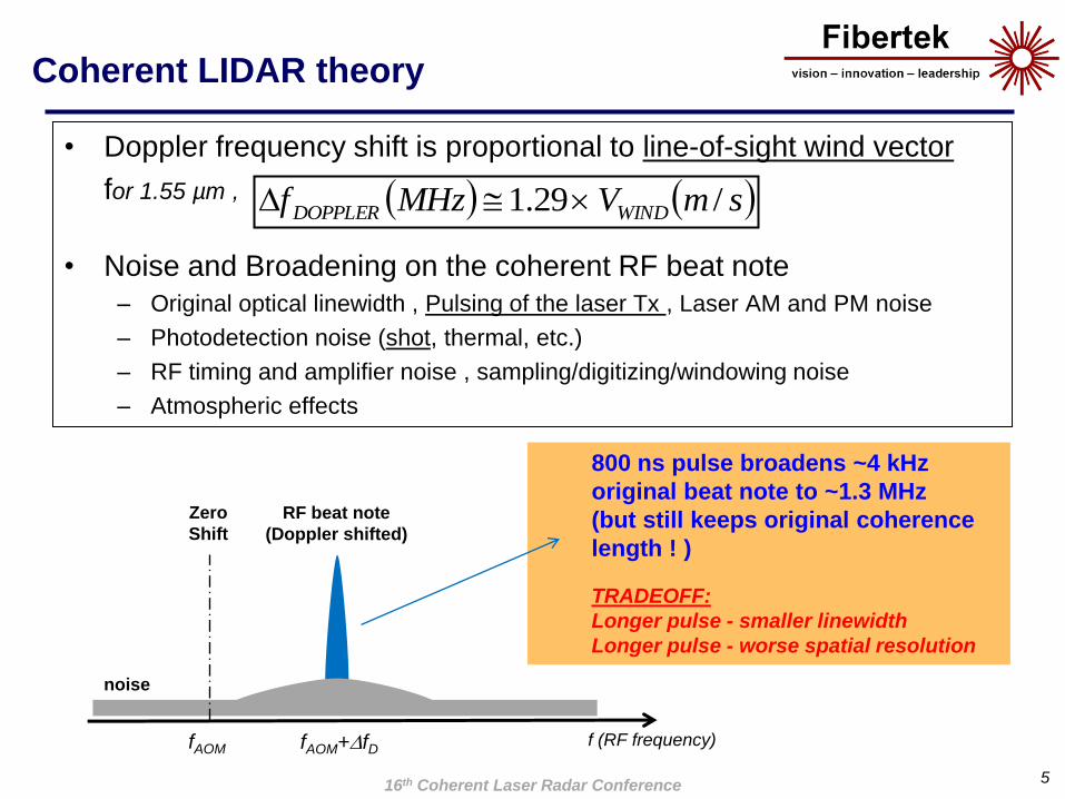
Coherent LIDAR theory
• Doppler frequency shift is proportional to line-of-sight wind vector
for 1.55 µm ,
• Noise and Broadening on the coherent RF beat note
– Original optical linewidth , Pulsing of the laser Tx , Laser AM and PM noise
– Photodetection noise (shot, thermal, etc.)
– RF timing and amplifier noise , sampling/digitizing/windowing noise
– Atmospheric effects
5
f (RF frequency)fAOM fAOM+fD
800 ns pulse broadens ~4 kHz
original beat note to ~1.3 MHz
(but still keeps original coherence
length ! )
TRADEOFF:
Longer pulse - smaller linewidth
Longer pulse - worse spatial resolution
smVMHzf WINDDOPPLER /29.1
RF beat note
(Doppler shifted)
Zero
Shift
16th Coherent Laser Radar Conference
noise

Challenges for airborne Wake-Vortex LIDAR
• Forward-looking airborne wake-vortex measurement– Axial line-of-sight reduces dynamic range (Need very fine resolution)
– Need accurate measurement of platform speed, attitude, etc.
– SWaP and Cost limitations (multi-function instrument ? )
– Dynamic wake trajectories and other atmospheric effects
– Scanning geometry limitations (dynamic observer)
6
~ 3º
Landing
Speed
~75 m/s
Wake-vortex
wind velocity
0-20 m/s
74.9 m/s
< 1 m/s
(1.3MHz)
Ground
LIDAR
LIDAR
< 10 m/s (13 MHz)
(>30º angle)
16th Coherent Laser Radar Conference

Coherent Lidar
Transceiver Development
716th Coherent Laser Radar Conference
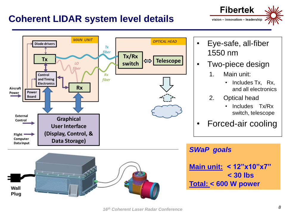
Coherent LIDAR system level details
8
• Eye-safe, all-fiber
1550 nm
• Two-piece design
1. Main unit:
• Includes Tx, Rx,
and all electronics
2. Optical head
• Includes Tx/Rx
switch, telescope
• Forced-air cooling
SWaP goals
Main unit: < 12”x10”x7”
< 30 lbs
Total: < 600 W power
Tx
Diode drivers
Controland TimingElectronics
PowerBoard
AircraftPower
FlightComputerData Input
ExternalControl
MAIN UNIT OPTICAL HEAD
Txfiber
Tx/Rx switch Telescope
Rxfiber
LOfiber
GraphicalUser Interface
(Display, Control, & Data Storage)
Rx
16th Coherent Laser Radar Conference
Wall
Plug

LIDAR performance simulations
• TASS data for a Boeing-747 landing supplied by NASA
9
Wake age: 24 sec
Min: -1.29 m/s , Max: 2.46 m/s
Wake age: 24 sec
Min: -2.09 m/s , Max: 2.61 m/s
Wake age: 60 sec
Fibertek LIDAR
Scan simulations
(<7m x-y resolution)
TASS Data
(<1.25m x-y resolution)
16th Coherent Laser Radar Conference

Range versus energy estimation
• 25 kHz rep. rate
• 5cm Rx aperture
• Final SNR=6
• 40 averages
(>600 Hz data)
– 120µJ , ~1.7 km
– 500µJ , ~2.7 km
• 2500 averages
(10 Hz data)
– 120µJ , ~3.2 km
– 500µJ , ~5 km
10
0
1
2
3
4
5
6
0 100 200 300 400 500 600
Ra
nge
(km
)
Pulse Energy (microJoules)
40 averages
2500 averages
16th Coherent Laser Radar Conference

Fiber-Optic Lidar Transmitter (Tx)
Performance limitations
• Fiber lasers optimal for – High average power, High repetition rate, Narrow linewidth, Flexible operation, Data
modulation capabilities, Wall-plug efficiency, SWaP metrics, Production cost and repeatability
• Fiber lasers not optimal for– High energy (~mJ single mode), high peak power (~MW short pulse)
• Stimulated Brillouin Scattering (SBS) is the main energy-limiting factor for
long pulses (800ns in this case)
– Energy goes backward stealing gain and causing catastrophic damage
– SBS threshold Equal peak levels backward ( < 35 dB below forward )
11
Fiber Amplifier
SBS
reflection
Normal
backscatterInput
Output
Original
Laser line
SBS
reflection
~1mW total 10W100mW
16th Coherent Laser Radar Conference

Lidar Tx - Design
• Eye-safe 1550 nm wavelength
• Master Oscillator Power Amplifier (MOPA) Architecture– Ultra-low noise Master Oscillator
• Acousto Optic Modulator (AOM) for pulsing– High extinction ratio Pulse Carving
– Optical frequency shifting of TR/REC with respect to LO
• All PM Erbium-doped fibers for amplification– Multi-stage MOPA for lowest noise with highest gain
– Increasing MFD at each stage, COTS LMA fibers
• Proprietary techniques for SBS mitigation
1216th Coherent Laser Radar Conference

0 0.2 0.4 0.6 0.8 1-80
-70
-60
-50
-40
-30
-20
-10
0
RF Frequency Offset(MHz)
S(f
) (d
B s
cale
)
RBW=150Hz, VBW=100Hz measurement
Extended Fit
20-dB Lorentzian fit
Voigt Fit
103
104
105
106
107
-160
-150
-140
-130
-120
-110
-100
RF Frequency (Hz)
S(f
) (d
Bc/H
z)
Relative Intensity Noise
Measurement Noise Floor
Lidar Tx – Master Oscillator
• Ultra-low noise 1550nm master
oscillator (RIO Inc.):
• Semiconductor + PLC based
• ~2.5 kHz linewidth
• -140 dBc/Hz RIN noise
• SWaP efficient
• Pulsed with external AOM at
25 kHz, 800 ns pulse width
13
Linewidth measurement
RIN measurement
16th Coherent Laser Radar Conference

Lidar Tx – Power Amplifier
0
5
10
15
20
25
0 20 40 60 80
Un
its
(W o
r %
)
Coupled Pump Power (W)
Output Power (W)
Estimated O/O eff. (%)
100uJ
500uJ
(Preliminary)
Beam Pointing
<50 µrad in 30 min.
• PM LMA commercial Er-doped fiber
• Up to ~65 W coupled pump
• Up to ~14 W output power (~21% eff.)
• ~17 dB PER measured
• Single Mode (M2 < 1.2) , stable pointing
(even with bare fiber tip and standard optic
mounts)
1416th Coherent Laser Radar Conference
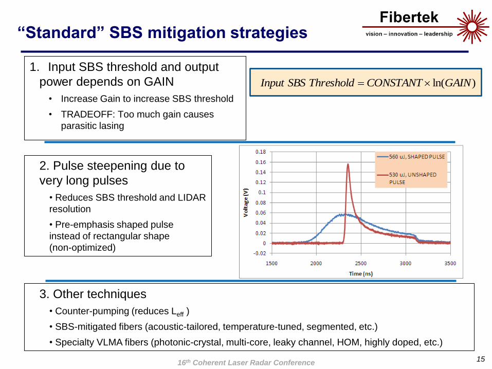
“Standard” SBS mitigation strategies
1. Input SBS threshold and output
power depends on GAIN
• Increase Gain to increase SBS threshold
• TRADEOFF: Too much gain causes
parasitic lasing
15
)ln(GAINCONSTANTThresholdSBSInput
2. Pulse steepening due to
very long pulses
• Reduces SBS threshold and LIDAR
resolution
• Pre-emphasis shaped pulse
instead of rectangular shape
(non-optimized)
3. Other techniques
• Counter-pumping (reduces Leff )
• SBS-mitigated fibers (acoustic-tailored, temperature-tuned, segmented, etc.)
• Specialty VLMA fibers (photonic-crystal, multi-core, leaky channel, HOM, highly doped, etc.)
16th Coherent Laser Radar Conference

Tx output with “standard” SBS mitigation
Gain optimization and Pulse Shaping
16
Backward optical spectrum
Forward optical spectrum
Time domain
• Increased gain in amplifiers
while controlling ASE levels
• Implemented pre-emphasis
pulse shaping (non-optimized)
Normal
Backscatter
SBS
reflection
120 J @ 25kHz
220 J @ 10kHz
at SBS threshold and low ASE
16th Coherent Laser Radar Conference

Tx output with “advanced” SBS mitigation
• Proprietary Fibertek techniques
• SBS threshold increase beyond
standard methods
17
Backward optical spectrum
Forward optical spectrum
Time domain
560 J @ 25kHz
800 J @ 10kHz
(pump limited)
with minimal SBS and ASE
Normal
Backscatter
SBS
reflection
16th Coherent Laser Radar Conference

Solid
State
Erbium
fiber
Survey and simple comparison
• LIDAR performance figure-of-merit (FOM) for fixed Rx aperture:
18
PRFENERGYFOM
LIDAR Vendor-Model Energy (mJ) PRF (Hz) FOM
LM-CTI WindTracer 2 500 45
LM-CTI WindTracerX 5 500 112
NASA-LaRC DAWN 250 10 790
Onera-Leosphere 0.12 12000 13
ENRI-Mitsubishi 0.2 4000 13
Fibertek 120 µJ standard 0.12 25000 19
Fibertek 220 µJ standard 0.22 10000 22
Fibertek 560 µJ advanced 0.56 25000 88
Fibertek 800 µJ advanced 0.80 10000 80
16th Coherent Laser Radar Conference

Receiver (Rx) Design
• Receiver is comprised of two parts:
– Analog board (Coherent, balanced photodetection, Platform velocity correction)
– Digital board (Gs/s sampling , Real-time DSP and curve-fitting, I/Q, Gb/s data interface)
• Analog board sensitivity of ~ 2 fW (SNR=6)
• Wind velocity measurement range of ± 20 m/s with ~0.1 m/s resolution
• Airborne platform velocity correction of ~20 – 200 m/s (data read from external GPS)
• ~40-120m range slice resolution
• <3.5 sec. data refresh rate (40 pulse avg., ~2000 pixels for certain scanning
geometries)
19
Analog
Board
50/50
coupler
Lidar
return
Local
Laser
Oscillator
Digital
Board
Mixer
RF tone
Flight Computer
(INS, GPS) Data
Raw and
Processed Data
to Display
Unit
Trigger
timing
Control
Bus
16th Coherent Laser Radar Conference

Preliminary Lidar Testing
2016th Coherent Laser Radar Conference

50 52 54 56 58 600
0.2
0.4
0.6
0.8
1
1.2
1.4
1.6
RF Frequency (MHz)
Po
wer
(a.u
.)
Stationary
Vel.1
Vel.2
Vel.3
Vel.4
Lidar Tx + Rx – Preliminary lab experiments
1. Compare back-to-back and
25 km of SMF28 delay• ~18.5 km range in air
• ~1µW received power (40 pJ)
• Zero Doppler shift=55 MHz
21
Lidar
Tx
Variable
motor
velocityLidar
Rx
2. Test with variable target velocity and
partially-completed receiver• ~0.1 MHz (< 0.1 m/s) resolution
• ~100 pW received power (4 fJ)
Lidar
Tx
Lidar
Rx
25 km
SMF28
-100
-90
-80
-70
-60
-50
-40
40 45 50 55 60 65 70
Po
we
r (d
B s
cale
)
RF Frequency (MHz)
25 km fiber
Back-to-back
16th Coherent Laser Radar Conference
Coherence Length
Sensitivity
Resolution
Conclusions
• We present a fiber-optic, eye-safe Coherent LIDAR
transceiver
– 560µJ of energy at 25 kHz rate, 800µJ@10kHz (pump limited)
– 800 ns pulsewidth with <3kHz local oscillator optical linewidth
– ~2 fW estimated receiver sensitivity with >2 km range
– Velocity measurement of ± 20 m/s with ~0.1 m/s resolution
– Desirable SWAP metrics for airborne platform
• We believe that this lidar can be a useful tool for airborne
wind sensing, turbulence and wake-vortex detection
2216th Coherent Laser Radar Conference