fibre plus dispersion
TRANSCRIPT

8/13/2019 Fibre Plus Dispersion
http://slidepdf.com/reader/full/fibre-plus-dispersion 1/89
The Basics of Fiber
Optics
Fiber Optics
8/13/2019 Fibre Plus Dispersion
http://slidepdf.com/reader/full/fibre-plus-dispersion 2/89

8/13/2019 Fibre Plus Dispersion
http://slidepdf.com/reader/full/fibre-plus-dispersion 3/89

8/13/2019 Fibre Plus Dispersion
http://slidepdf.com/reader/full/fibre-plus-dispersion 4/89
Introduction
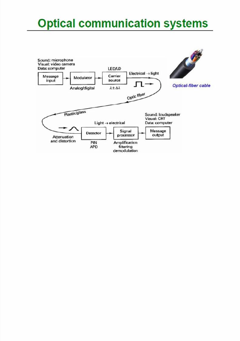
An optical fiber is essentially a waveguide for lightIt consists of a core and cladding that surrounds core
The index of refraction of the cladding is less than that of the
core, causing rays of light leaving the core to be refracted back intothe core
A light-emitting diode (LED) or laser diode (LD) can be used forthe source
Advantages of optical fiber include:• Greater bandwidth than copper• Lower loss• Immunity to crosstalk • No electrical hazard

8/13/2019 Fibre Plus Dispersion
http://slidepdf.com/reader/full/fibre-plus-dispersion 5/89
Advantages of Fiber
• Fiber has these advantages compared with metal wires
• Bandwidth – more data per second
• Longer distance
• Faster
• Special applications like medical imaging and quantum
key distribution are only possible with fiber because they
use light directly

8/13/2019 Fibre Plus Dispersion
http://slidepdf.com/reader/full/fibre-plus-dispersion 6/89
Elements of a Fiber Data Link
• Transmitter emits light pulses (LED or Laser)
• Connectors and Cables passively carry the pulses
• Receiver detects the light pulses
Transmitter ReceiverCable

8/13/2019 Fibre Plus Dispersion
http://slidepdf.com/reader/full/fibre-plus-dispersion 7/89
Repeaters
• For long links, repeaters are needed to compensate for signal loss
FiberRepeaterRepeater Repeater
Fiber FiberFiber
• Optical fiber transmits light pulses
• Can be used for analog or digital transmission
• Voice, computer data, video, etc.
• Copper wires (or other metals) can carry the same types of signals with
electrical pulses
Fiber v. Copper (comparison)

8/13/2019 Fibre Plus Dispersion
http://slidepdf.com/reader/full/fibre-plus-dispersion 8/89
Optical Fiber
• Optical fiber is made from thin strands of either glass or
plastic• It has little mechanical strength, so it must be enclosed in a
protective jacket
• Often, two or more fibers are enclosed in the same cablefor increased bandwidth and redundancy in case one of thefibers breaks
• It is also easier to build a full-duplex system using twofibers, one for transmission in each direction

8/13/2019 Fibre Plus Dispersion
http://slidepdf.com/reader/full/fibre-plus-dispersion 9/89
Optical Fiber
• Core• Glass or plastic with a higher index of
refraction than the cladding
• Carries the signal
• Cladding• Glass or plastic with a lower index of
refraction than the core
• Buffer
• Protects the fiber from damage andmoisture
• Jacket
• Holds one or more fibers in a cable

8/13/2019 Fibre Plus Dispersion
http://slidepdf.com/reader/full/fibre-plus-dispersion 10/89
Optical Fiber & Communications System

8/13/2019 Fibre Plus Dispersion
http://slidepdf.com/reader/full/fibre-plus-dispersion 11/89
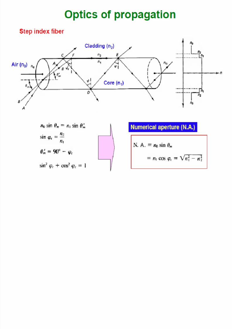
Optical fibers work on the principle of total
internal reflection. With light, the refractiveindex is listed The angle of refraction at theinterface between two media is governed bySnell’s law: n1sin 1 n2 sin 2
Total Internal Reflection

8/13/2019 Fibre Plus Dispersion
http://slidepdf.com/reader/full/fibre-plus-dispersion 12/89
Index of Refraction
• When light enters a dense medium like glass orwater, it slows down
• The index of refraction (n) is the ratio of the speed
of light in vacuum to the speed of light in themedium
• Water has n = 1.3• Light takes 30% longer to travel through it
• Fiber optic glass has n = 1.5• Light takes 50% longer to travel through it
8/13/2019 Fibre Plus Dispersion
http://slidepdf.com/reader/full/fibre-plus-dispersion 13/89
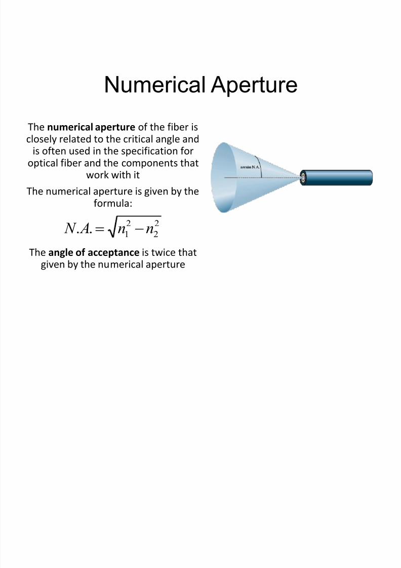
The numerical aperture of the fiber is
closely related to the critical angle andis often used in the specification for
optical fiber and the components thatwork with it
The numerical aperture is given by theformula:
The angle of acceptance is twice thatgiven by the numerical aperture
2
2
2
1.. nn A N
Numerical Aperture

8/13/2019 Fibre Plus Dispersion
http://slidepdf.com/reader/full/fibre-plus-dispersion 14/89
Numerical Aperture
• If the core and cladding have almost the same index
of refraction, the numerical aperture will be small
• This means that light must be shooting right down
the center of the fiber to stay in the core
8/13/2019 Fibre Plus Dispersion
http://slidepdf.com/reader/full/fibre-plus-dispersion 15/89

8/13/2019 Fibre Plus Dispersion
http://slidepdf.com/reader/full/fibre-plus-dispersion 16/89
Multimode Fiber
• Can transmit more than a single mode
• Relatively inexpensive
• Easy to couple with LEDs and detectors
• Large bandwidth
• NA ~ 0.20
Types of FiberSingle-Mode Fiber
– Allows only a single mode to propagate
– Difficult to handle and couple – More expensive
– Requires a laser source
– Large bandwidth
– High speed/large bandwidth systems – NA ~ 0.12

8/13/2019 Fibre Plus Dispersion
http://slidepdf.com/reader/full/fibre-plus-dispersion 17/89
Types of Fiber
8/13/2019 Fibre Plus Dispersion
http://slidepdf.com/reader/full/fibre-plus-dispersion 18/89
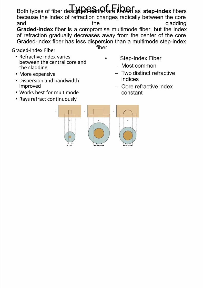
Types of FiberBoth types of fiber described earlier are known as step-index fibersbecause the index of refraction changes radically between the coreand the claddingGraded-index fiber is a compromise multimode fiber, but the index
of refraction gradually decreases away from the center of the coreGraded-index fiber has less dispersion than a multimode step-index
fiberGraded-Index Fiber
• Refractive index variesbetween the central core andthe cladding
• More expensive
• Dispersion and bandwidthimproved
• Works best for multimode
• Rays refract continuously
• Step-Index Fiber
– Most common
– Two distinct refractiveindices
– Core refractive indexconstant

8/13/2019 Fibre Plus Dispersion
http://slidepdf.com/reader/full/fibre-plus-dispersion 19/89
Singlemode Fiber
• Singlemode fiber has a core diameter of 8 to 9 microns, which only
allows one light path or mode
• Images from arcelect.com
Index ofrefraction

8/13/2019 Fibre Plus Dispersion
http://slidepdf.com/reader/full/fibre-plus-dispersion 20/89
Multimode Step-Index Fiber
• Multimode fiber has a core diameter of 50 or 62.5 microns (sometimes
even larger)
• Allows several light paths or modes
• This causes modal dispersion – some modes take longer to
pass through the fiber than others because they travel a
longer distance
• See animation at link Ch 2f
Index ofrefraction
8/13/2019 Fibre Plus Dispersion
http://slidepdf.com/reader/full/fibre-plus-dispersion 21/89
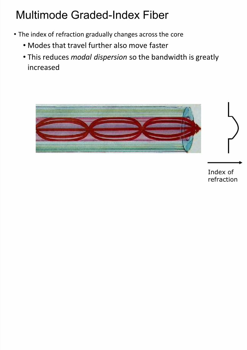
Multimode Graded-Index Fiber
• The index of refraction gradually changes across the core
• Modes that travel further also move faster
• This reduces modal dispersion so the bandwidth is greatly
increased
Index ofrefraction
8/13/2019 Fibre Plus Dispersion
http://slidepdf.com/reader/full/fibre-plus-dispersion 22/89
Step-index and Graded-index
• Step index multimode was developed first, but rare today because it
has a low bandwidth (50 MHz-km)
• It has been replaced by graded-index multimode with a bandwidth
up to 2 GHz-km.
• Large core (1 mm) step-index multimode fiber
• Easy to cut and work with, but high attenuation (1 dB /
meter) makes it useless for long distances
Plastic Optical Fiber

8/13/2019 Fibre Plus Dispersion
http://slidepdf.com/reader/full/fibre-plus-dispersion 23/89
Special Fiber Types
Plastic Fiber• High attenuation
• Less expensive than glass• Easy to work with
• Step-index fibers
• Used in automobiles, consumer products, industrial control, andsmall LANs
Dispersion-Shifted Fiber
– Adjusts for pulse spreading caused by material and
waveguide dispersion
Photonic Crystal (Holey) Fibers
– Dispersion can be controlled – Nonlinear properties
– Single-mode
– Wide wavelength
– Cladding region consists of air holes
– Two categories: High-index and low-index guiding fibers

8/13/2019 Fibre Plus Dispersion
http://slidepdf.com/reader/full/fibre-plus-dispersion 24/89
Special Fiber Types
Plastic Fiber• High attenuation
• Less expensive than glass• Easy to work with
• Step-index fibers
• Used in automobiles, consumer products, industrial control, andsmall LANs
Dispersion-Shifted Fiber
– Adjusts for pulse spreading caused by material and
waveguide dispersion
Photonic Crystal (Holey) Fibers
– Dispersion can be controlled – Nonlinear properties
– Single-mode
– Wide wavelength
– Cladding region consists of air holes
– Two categories: High-index and low-index guiding fibers

8/13/2019 Fibre Plus Dispersion
http://slidepdf.com/reader/full/fibre-plus-dispersion 25/89
V-number in Optical Fiberswhere
• N is the number of modes• a is the radius of the fiber
• λ is the wavelength of light
For mode fiber if , V < 2.405
For mode fiber if, V > 2.405
2
2
2V N
aNAV
4
2V
N

8/13/2019 Fibre Plus Dispersion
http://slidepdf.com/reader/full/fibre-plus-dispersion 26/89
Examples of Dispersion

8/13/2019 Fibre Plus Dispersion
http://slidepdf.com/reader/full/fibre-plus-dispersion 27/89
INTRODUCTION
• Dispersion Fundamentals
• Light is spread out (in time) as it travels through the fiber
• Parameter: Pulse Widening (measured at 50%), Δt = TRX-TTX
• Dispersion causes INTERSYMBOL INTERFERENCE

8/13/2019 Fibre Plus Dispersion
http://slidepdf.com/reader/full/fibre-plus-dispersion 28/89
Fiber Dispersion
Dispersion is the spreading of a light pulse as itpropagates down the fiber. Dispersion may beeither modal or chromatic.
Modal Dispersion• The temporal spreading of a pulse in an optical
waveguide caused by modal effects
• Intermodal, or modal, dispersion occurs only inmultimode fibers.
• Contributes to pulse broadening

8/13/2019 Fibre Plus Dispersion
http://slidepdf.com/reader/full/fibre-plus-dispersion 29/89
Modes and Materials
• Since optical fiber is a waveguide, light can propagate in a number ofmodes
• If a fiber is of large diameter, light entering at different angles willexcite different modes while narrow fiber may only excite one mode
• Multimode propagation will cause dispersion, which results in thespreading of pulses and limits the usable bandwidth
• Single-mode fiber has much less dispersion but is more expensive toproduce. Its small size, together with the fact that its numericalaperture is smaller than that of multimode fiber, makes it moredifficult to couple to light sources

8/13/2019 Fibre Plus Dispersion
http://slidepdf.com/reader/full/fibre-plus-dispersion 30/89
Dispersion
• Dispersion in fiber optics results from the fact that in multimodepropagation, the signal travels faster in some modes than it would inothers
• Single-mode fibers are relatively free from dispersion except forintramodal dispersion
• Graded-index fibers reduce dispersion by taking advantage of higher-order modes
• One form of intramodal dispersion is called material dispersion because it depends upon the material of the core
• Another form of dispersion is called waveguide dispersion
• Dispersion increases with the bandwidth of the light source

8/13/2019 Fibre Plus Dispersion
http://slidepdf.com/reader/full/fibre-plus-dispersion 31/89
• Types of Dispersion
• Modal Dispersion, Δtmod
• Intermodal: between different modes
• Intramodal: inside each mode
• Chromatic Dispersion, Δtcro
• Mechanisms
• Material
• Waveguide
• PMD, Δtpmd
• Polarization Mode Dispersion
• Between orthogonal polarizations

8/13/2019 Fibre Plus Dispersion
http://slidepdf.com/reader/full/fibre-plus-dispersion 32/89
Material Dispersion• Material dispersion occurs because the spreading of a light pulse is
dependent on the wavelengths' interaction with the refractive indexof the fiber core.
• Material dispersion is a function of the source spectral width, whichspecifies the range of wavelengths that can propagate in the fiber.
• Material dispersion is less at longer wavelengths.
Waveguide dispersion
– Waveguide dispersion occurs because the modepropagation constant is a function of the size of the fiber'score relative to the wavelength of operation.
– Waveguide dispersion also occurs because light propagatesdifferently in the core than in the cladding.
Polarization Mode Dispersion
– Polarization mode dispersion (PMD) occurs when different
planes of light inside a fiber travel at slightly different speeds,
making it impossible to transmit data reliably at high speeds.

8/13/2019 Fibre Plus Dispersion
http://slidepdf.com/reader/full/fibre-plus-dispersion 33/89
8/13/2019 Fibre Plus Dispersion
http://slidepdf.com/reader/full/fibre-plus-dispersion 34/89
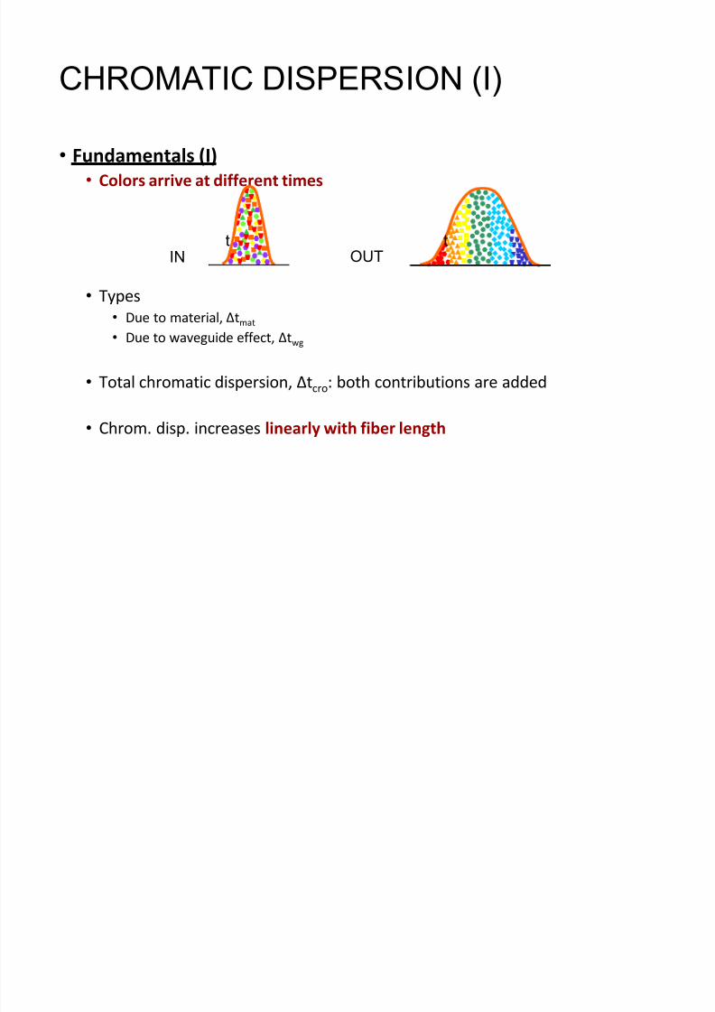
CHROMATIC DISPERSION (I)
• Fundamentals (I)
• Colors arrive at different times
• Types
• Due to material, Δtmat
• Due to waveguide effect, Δtwg
• Total chromatic dispersion, Δtcro: both contributions are added
• Chrom. disp. increases linearly with fiber length
IN
t
OUT
t

8/13/2019 Fibre Plus Dispersion
http://slidepdf.com/reader/full/fibre-plus-dispersion 35/89
-20
-10
0
10
20
Frequency (GHz)
0
0.2
0.4
0.6
0.8
Power
0
50
100
150
200
250
300
Time/Distance
Frequency components
of modulated signaltravel at different
velocities in fiber
Chromatic Dispersion

8/13/2019 Fibre Plus Dispersion
http://slidepdf.com/reader/full/fibre-plus-dispersion 36/89
t
Spread, ²
t 0
Spectrum, ²
1 2 o
Intensity Intensity Intensity
Cladding
CoreEmitter
Very short
light pulse
v g (
2)
v g ( 1)
Input
Output
All excitation sources are inherently non-monochromatic and emit within aspectrum, ² , of wavelengths. Waves in the guide with different free spacewavelengths t ravel at different group velocities due to the wavelength dep endenceof n1. The waves arrive at the end of the fiber at different t imes and hence result in
a broadened output p ulse.
© 1999 S.O. Kasap,Optoelectronics (Prentice Hall)
Material Dispersion
8/13/2019 Fibre Plus Dispersion
http://slidepdf.com/reader/full/fibre-plus-dispersion 37/89
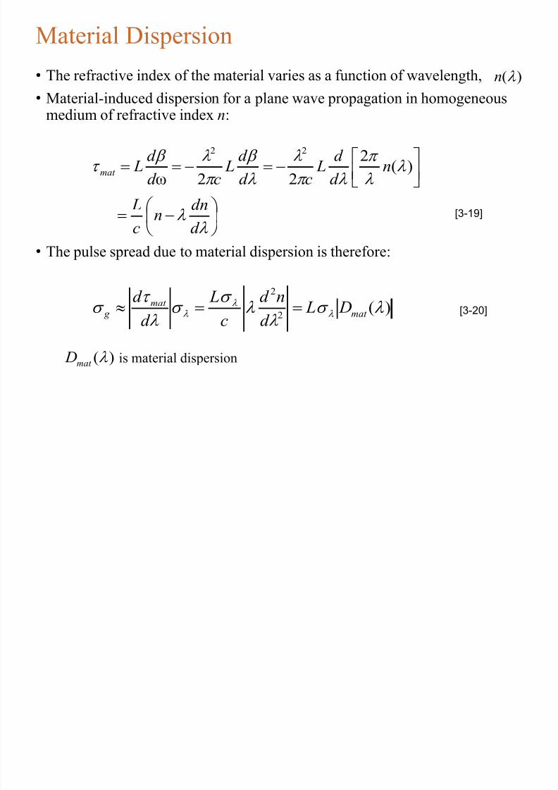
Material Dispersion
• The refractive index of the material varies as a function of wavelength,
• Material-induced dispersion for a plane wave propagation in homogeneousmedium of refractive index n:
• The pulse spread due to material dispersion is therefore:
)( n
d
dnn
c
L
nd
d L
cd
d L
cd
d Lmat
)(2
22ω
22
[3-19]
)(2
2
mat
mat g D L
d nd
c L
d d [3-20]
)( mat D is material dispersion

8/13/2019 Fibre Plus Dispersion
http://slidepdf.com/reader/full/fibre-plus-dispersion 38/89

8/13/2019 Fibre Plus Dispersion
http://slidepdf.com/reader/full/fibre-plus-dispersion 39/89
Dispersion in multimode fibre
31
4
8cn
NA Lt GI
1
2
2cn
NA Lt SI

8/13/2019 Fibre Plus Dispersion
http://slidepdf.com/reader/full/fibre-plus-dispersion 40/89
Fiber Dispersion
Total Dispersion
• Total dispersion is due to all types of dispersion
pol chromtot t t t t 22mod
2
Fiber Losses
– Absorption loss occurs at wavelengths greater than
1.55µm due to infrared vibration.
– Scattering can be significant at shorter wavelengths.
– Attenuation describes the total loss of a optical fiber
system
– Bending loss occurs when total internal reflection
deteriorates because of installation procedures.

8/13/2019 Fibre Plus Dispersion
http://slidepdf.com/reader/full/fibre-plus-dispersion 41/89
Group Velocity
• Wave Velocities:
• 1- Plane wave velocity: For a plane wave propagating along z -axis in anunbounded homogeneous region of refractive index , which isrepresented by , the velocity of constant phase plane is:
• 2- Modal wave phase velocity: For a modal wave propagating along z -axisrepresented by , the velocity of constant phase plane is:
3- For transmission system operation the most important & useful type ofvelocity is the group velocity, . This is the actual velocity which thesignal information & energy is traveling down the fiber. It is always less thanthe speed of light in the medium. The observable delay experiences by theoptical signal waveform & energy, when traveling a length of l along thefiber is commonly referred to as group delay.
1n
)ωexp( 1 z jk t j
11 n
c
k v
)ωexp( z jt j
ω
pv
g V

8/13/2019 Fibre Plus Dispersion
http://slidepdf.com/reader/full/fibre-plus-dispersion 42/89
Group Velocity & Group Delay• The group velocity is given by:
• The group delay is given by:
• It is important to note that all above quantities depend both on frequency &the propagation mode. In order to see the effect of these parameters ongroup velocity and delay, the following analysis would be helpful.
d
d V g
ω
[3-6]
ωd d l
V l
g
g [3-7]
Inp t/O tp t signals in Fiber Transmission
8/13/2019 Fibre Plus Dispersion
http://slidepdf.com/reader/full/fibre-plus-dispersion 43/89
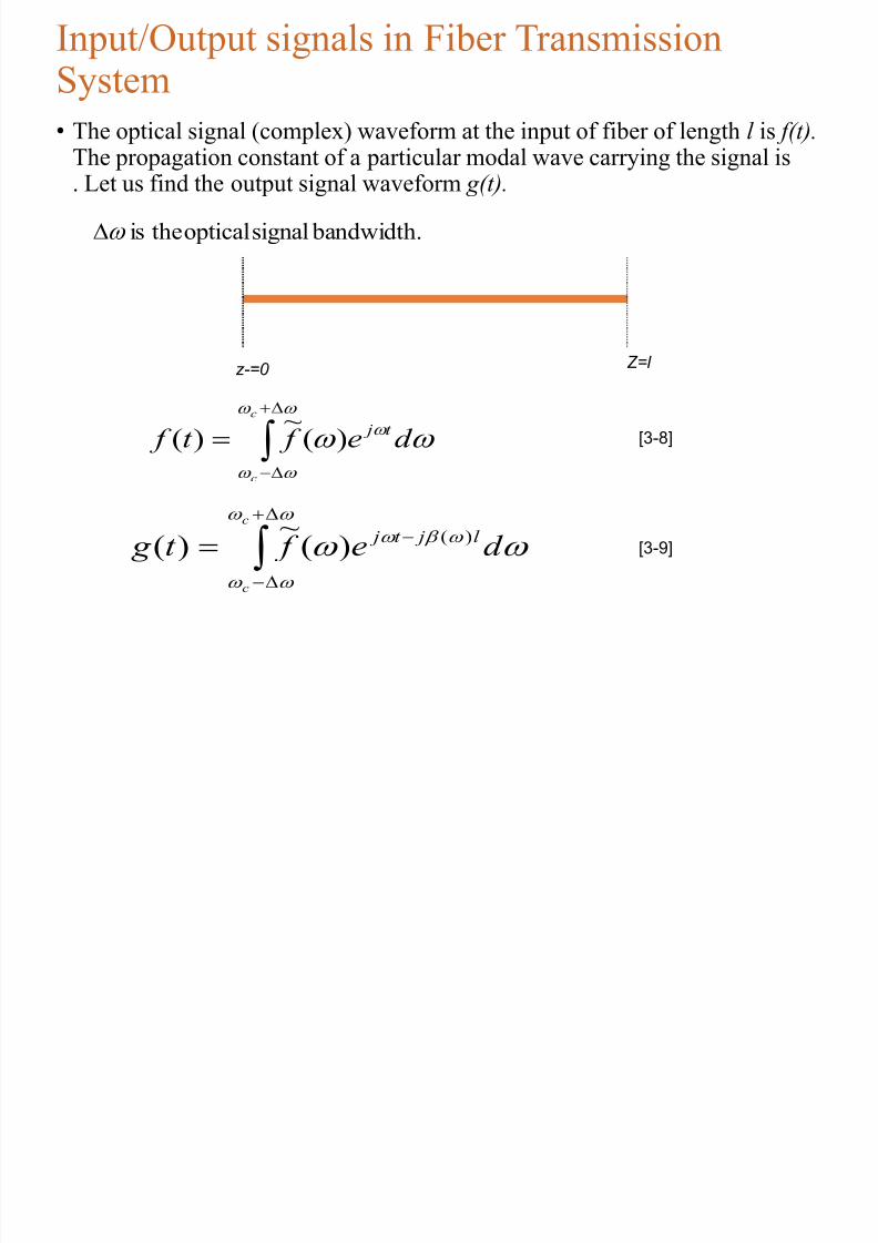
Input/Output signals in Fiber TransmissionSystem
• The optical signal (complex) waveform at the input of fiber of length l is f(t).
The propagation constant of a particular modal wave carrying the signal is. Let us find the output signal waveform g(t).
z-=0 Z=l
c
c
d e f t f t j
)(~
)( [3-8]
c
c
d e f t g l jt j )()(~
)( [3-9]
bandwidth.signalopticaltheis
If

8/13/2019 Fibre Plus Dispersion
http://slidepdf.com/reader/full/fibre-plus-dispersion 44/89
...)(2
1)()()(
If
2
2
2
ccc
c
ccd
d
d
d
)()(
)(~
)(~
)(~
)(
)()(
)(2/
2/
)(
)]()([2/
2/
)(
2/
2/
g
l jl j
d
d l t j
l j
l d
d jt j
l jt j
t f ed
d
l t f e
d e f e
d e f d e f t g
c
c
c
c
c
c
c
c
c
cc
c
c
c
g
g V
l
d
d l
c
[3-10]
[3-11]
[3-14]

8/13/2019 Fibre Plus Dispersion
http://slidepdf.com/reader/full/fibre-plus-dispersion 45/89
Intramodal Dispersion• As we have seen from Input/output signal relationship in optical fiber, the
output is proportional to the delayed version of the input signal, and the delay
is inversely proportional to the group velocity of the wave. Since the propagation constant, , is frequency dependent over band widthsitting at the center frequency , at each frequency, we have one
propagation constant resulting in a specific delay time. As the output signal iscollectively represented by group velocity & group delay this phenomenon iscalled intramodal dispersion or Group Velocity Dispersion (GVD). This
phenomenon arises due to a finite bandwidth of the optical source,dependency of refractive index on the wavelength and the modaldependency of the group velocity.
• In the case of optical pulse propagation down the fiber, GVD causes pulse
broadening, leading to Inter Symbol Interference (ISI).
)ω( ωcω
8/13/2019 Fibre Plus Dispersion
http://slidepdf.com/reader/full/fibre-plus-dispersion 46/89
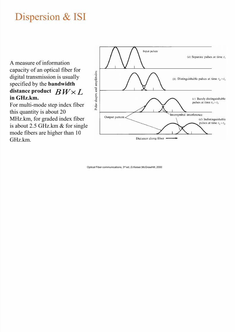
Dispersion & ISI
Optical Fiber communications, 3rd ed.,G.Keiser,McGrawHill, 2000
A measure of information
capacity of an optical fiber for
digital transmission is usually
specified by the bandwidthdistance product
in GHz.km.
For multi-mode step index fiber
this quantity is about 20
MHz.km, for graded index fiber
is about 2.5 GHz.km & for singlemode fibers are higher than 10
GHz.km.
L BW
8/13/2019 Fibre Plus Dispersion
http://slidepdf.com/reader/full/fibre-plus-dispersion 47/89
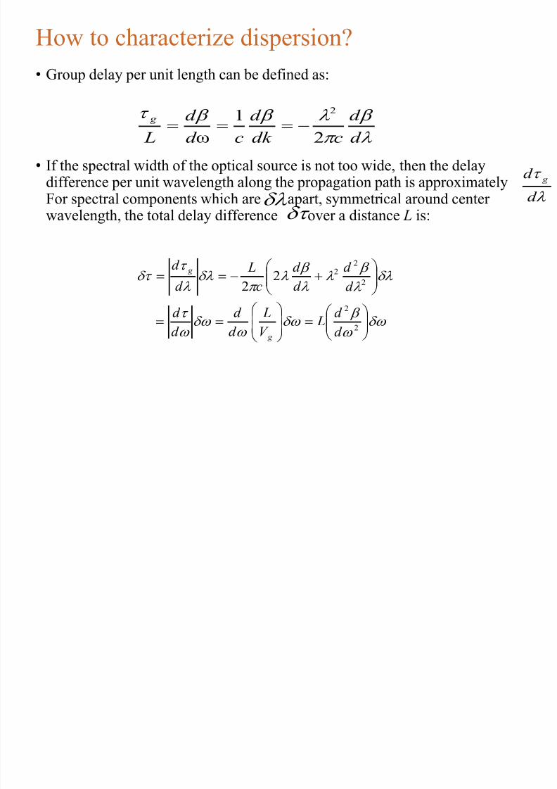
How to characterize dispersion?
• Group delay per unit length can be defined as:
• If the spectral width of the optical source is not too wide, then the delaydifference per unit wavelength along the propagation path is approximately
For spectral components which are apart, symmetrical around centerwavelength, the total delay difference over a distance L is:
d
d
cdk
d
cd
d
L
g
2
1
ω
2
d
d g
2
2
2
22
22
d
d L
V
L
d
d
d
d
d
d
d
d
c
L
d
d
g
g
2
d
8/13/2019 Fibre Plus Dispersion
http://slidepdf.com/reader/full/fibre-plus-dispersion 48/89
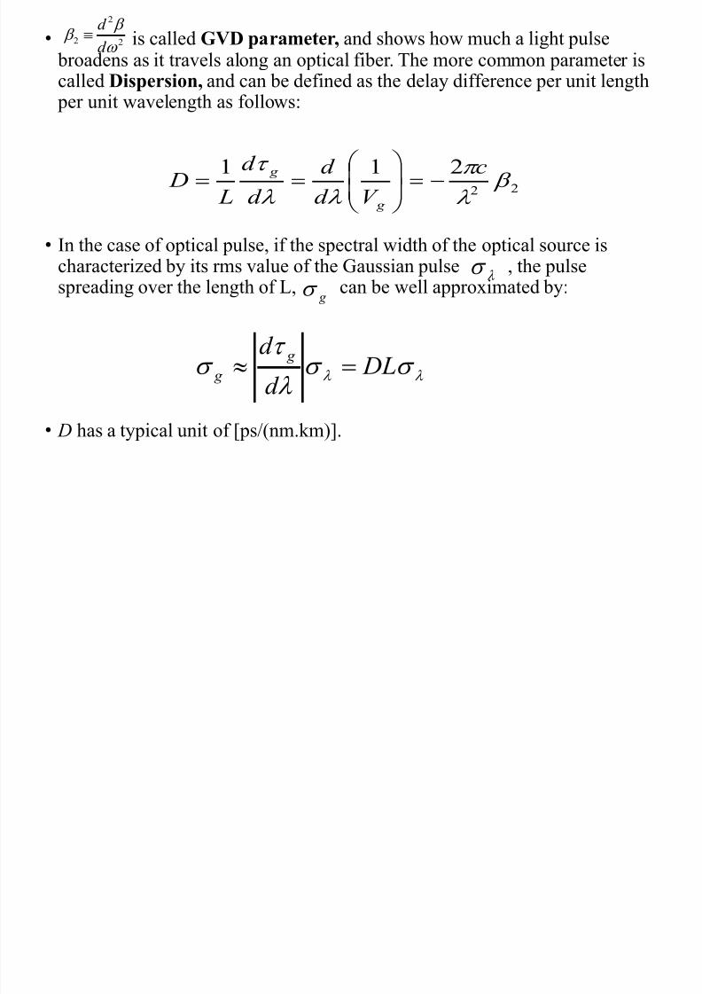
• is called GVD parameter, and shows how much a light pulse broadens as it travels along an optical fiber. The more common parameter iscalled Dispersion, and can be defined as the delay difference per unit length
per unit wavelength as follows:
• In the case of optical pulse, if the spectral width of the optical source ischaracterized by its rms value of the Gaussian pulse , the pulsespreading over the length of L, can be well approximated by:
• D has a typical unit of [ps/(nm.km)].
22
d
d
22
211
c
V d
d
d
d
L D
g
g
g
DLd
d g g
M i l Di i

8/13/2019 Fibre Plus Dispersion
http://slidepdf.com/reader/full/fibre-plus-dispersion 49/89
t
Spread, ²
t 0
Spectrum, ²
1 2 o
Intensity Intensity Intensity
Cladding
CoreEmitter
Very short
light pulse
v g ( 2)
v g (
1)
Input
Output
All excitation sources are inherently non-monochromatic and emit within a
spectrum, ² , of wavelengths. Waves in the guide with different free spacewavelengths travel at different group velocities due to the wavelength dependenceof n1. The waves arrive at the end of the fiber at different times and hence result in
a broadened output pulse.
© 1999 S.O. Kasap,Optoelectronics (Prentice Hall)
Material Dispersion

8/13/2019 Fibre Plus Dispersion
http://slidepdf.com/reader/full/fibre-plus-dispersion 50/89
Material Dispersion
• The refractive index of the material varies as a function of wavelength,
• Material-induced dispersion for a plane wave propagation in homogeneousmedium of refractive index n:
• The pulse spread due to material dispersion is therefore:
)( n
d
dnn
c
L
nd
d L
cd
d L
cd
d Lmat
)(2
22ω
22
)(2
2
mat
mat g D L
d nd
c L
d d
)( mat D is material dispersion

8/13/2019 Fibre Plus Dispersion
http://slidepdf.com/reader/full/fibre-plus-dispersion 51/89
Material Dispersion Diagrams
Optical Fiber communications, 3rd ed.,G.Keiser,McGrawHill, 2000
W id Di i

8/13/2019 Fibre Plus Dispersion
http://slidepdf.com/reader/full/fibre-plus-dispersion 52/89
Waveguide Dispersion
• Waveguide dispersion is due to the dependency of the group velocity of thefundamental mode as well as other modes on the V number, (see Fig 2-18 of
the textbook). In order to calculate waveguide dispersion, we consider that n is not dependent on wavelength. Defining the normalized propagationconstant b as:
• solving for propagation constant:
• Using V number:
21
22
2
2
1
2
2
22//
nn
nk
nn
nk b
[3-21]
)1(2 bk n [3-22]
2)( 2
2/12
2
2
1 kannnkaV [3-23]

8/13/2019 Fibre Plus Dispersion
http://slidepdf.com/reader/full/fibre-plus-dispersion 53/89
Waveguide Dispersion
• Delay time due to waveguide dispersion can then be expressed as:
dV
Vbd nn
c
Lwg
)(22 [3-24]
Optical Fiber communications, 3rd ed.,G.Keiser,McGrawHill, 2000

8/13/2019 Fibre Plus Dispersion
http://slidepdf.com/reader/full/fibre-plus-dispersion 54/89
Waveguide dispersion in single mode fibers
• For single mode fibers, waveguide dispersion is in the same order of material
dispersion. The pulse spread can be well approximated as:
2
2
2 )()(
dV
Vbd V
c
Ln D L
d
d wg
wg
wg
[3-25]
Optical Fiber communications, 3rd ed.,G.Keiser,McGrawHill, 2000
)( wg D

8/13/2019 Fibre Plus Dispersion
http://slidepdf.com/reader/full/fibre-plus-dispersion 55/89
Losses
• Losses in optical fiber result from attenuation in the materialitself and from scattering, which causes some light to strike thecladding at less than the critical angle
• Bending the optical fiber too sharply can also cause losses bycausing some of the light to meet the cladding at less than thecritical angle
• Losses vary greatly depending upon the type of fiber
• Plastic fiber may have losses of several hundred dB per kilometer• Graded-index multimode glass fiber has a loss of about 2 –4 dBper kilometer
• Single-mode fiber has a loss of 0.4 dB/km or less

8/13/2019 Fibre Plus Dispersion
http://slidepdf.com/reader/full/fibre-plus-dispersion 56/89
Fiber Loss
0
0.2
0.4
0.6
0.8
1
0 20 40 60 80 100
Distance (km)
F r a c t i o n o
f P o w e r
R e m a
i n i n g
80 km 100x loss
A i (fib l )

8/13/2019 Fibre Plus Dispersion
http://slidepdf.com/reader/full/fibre-plus-dispersion 57/89
Attenuation (fiber loss)
• Power loss along a fiber:
• The parameter is called fiber attenuation coefficient in a units of for
example [1/km] or [nepers/km]. A more common unit is [dB/km] that isdefined by:
Z=0
P(0) mW
Z= ll pe P l P
)0()( mw
z pe P z P
)0()( [3-1]
p
]km/1[343.4)(
)0(log
10]dB/km[
pl P
P
l
[3-2]
T f L

8/13/2019 Fibre Plus Dispersion
http://slidepdf.com/reader/full/fibre-plus-dispersion 58/89
Types of Losses
1. Macro bending
2 Mi b di L

8/13/2019 Fibre Plus Dispersion
http://slidepdf.com/reader/full/fibre-plus-dispersion 59/89
2. Microbending Loss
• Microbending Loss:microscopic bends of the fiberaxis that can arise when thefibers are incorporated intocables. The power is dissipated
through the microbended fiber, because of the repetitivecoupling of energy betweenguided modes & the leaky orradiation modes in the fiber.
Optical Fiber communications, 3rd ed.,G.Keiser,McGrawHill, 2000
3 Ab i

8/13/2019 Fibre Plus Dispersion
http://slidepdf.com/reader/full/fibre-plus-dispersion 60/89
3. Absorption
• Absorption is caused by three different mechanisms:1- Impurities in fiber material: from transition metal ions (must be in order of ppb) & particularly from OH ions with absorption peaks at wavelengths 2700 nm, 400 nm, 950 nm & 725nm.
2- Intrinsic absorption (fundamental lower limit): electronicabsorption band (UV region) & atomic bond vibration band (IRregion) in basic SiO2.
3- Radiation defects
4 S i L
8/13/2019 Fibre Plus Dispersion
http://slidepdf.com/reader/full/fibre-plus-dispersion 61/89
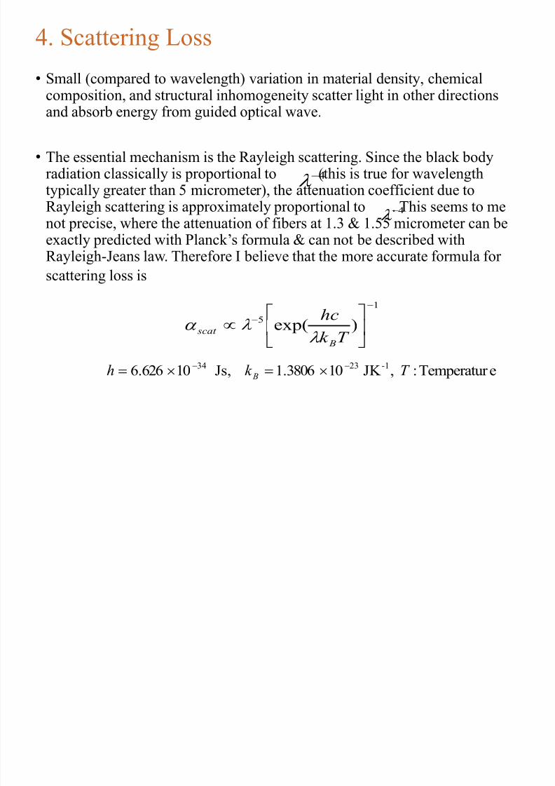
4. Scattering Loss
• Small (compared to wavelength) variation in material density, chemicalcomposition, and structural inhomogeneity scatter light in other directionsand absorb energy from guided optical wave.
• The essential mechanism is the Rayleigh scattering. Since the black bodyradiation classically is proportional to (this is true for wavelengthtypically greater than 5 micrometer), the attenuation coefficient due toRayleigh scattering is approximately proportional to . This seems to menot precise, where the attenuation of fibers at 1.3 & 1.55 micrometer can beexactly predicted with Planck’s formula & can not be described withRayleigh-Jeans law. Therefore I believe that the more accurate formula for
scattering loss is
4
4
1
5)exp(
T k
hc
B
scat
eTemperatur : ,JK 103806.1 Js, 10626.6-12334 T k h B
8/13/2019 Fibre Plus Dispersion
http://slidepdf.com/reader/full/fibre-plus-dispersion 62/89
Sources and Wavelengths
• Multimode fiber is used with
• LED sources at wavelengths of 850 and 1300 nm for slower local area
networks
• Lasers at 850 and 1310 nm for networks running at gigabits per second or
more
• Singlemode fiber is used with
• Laser sources at 1300 and 1550 nm
• Bandwidth is extremely high, around 100 THz-km

8/13/2019 Fibre Plus Dispersion
http://slidepdf.com/reader/full/fibre-plus-dispersion 63/89
Fiber Optic Specifications
• Attenuation
• Loss of signal, measured in dB
• Dispersion
• Blurring of a signal, affects bandwidth
• Bandwidth• The number of bits per second that can be sent through a data link
• Numerical Aperture
• Measures the largest angle of light that can be accepted into the core

8/13/2019 Fibre Plus Dispersion
http://slidepdf.com/reader/full/fibre-plus-dispersion 64/89
Attenuation and Dispersion
• See animation at link
Ch 2e

8/13/2019 Fibre Plus Dispersion
http://slidepdf.com/reader/full/fibre-plus-dispersion 65/89
Measuring Bandwidth
•The bandwidth-distance product in units of
MHz × km shows how fast data can be sent
through a cable•A common multimode fiber with bandwidth-
distance product of 500 MHz × km could carry• A 500 MHz signal for 1 km, or
• A 1000 MHz signal for 0.5 km
• From Wikipedia

8/13/2019 Fibre Plus Dispersion
http://slidepdf.com/reader/full/fibre-plus-dispersion 66/89
Fiber Types and Specifications
• From Lennie Lightwave (www.jimhayes.com/lennielw/fiber.html)

8/13/2019 Fibre Plus Dispersion
http://slidepdf.com/reader/full/fibre-plus-dispersion 67/89
Popular Fiber Types
• At first there were only
two common types of fiber
• 62.5 micron multimode, intended for LEDs and 100 Mbps networks
• There is a large installed base of 62.5 micron fiber
• 8 micron single-mode for long distances or high bandwidths, requiring laser
sources
• Corning’s SMF-28 fiber is the largest base of installed fiber in the world (links Ch 2j, 2k)

8/13/2019 Fibre Plus Dispersion
http://slidepdf.com/reader/full/fibre-plus-dispersion 68/89
Gigabit Ethernet
• 62.5 micron multimode fiber did not have enough bandwidth for
Gigabit Ethernet (1000 Mbps)
• LEDs cannot be used as sources for Gigabit Ethernet – they are too
slow
• So Gigabit Ethernet used a new, inexpensive source:
• Vertical Cavity Surface Emitting Laser (VCSEL)

8/13/2019 Fibre Plus Dispersion
http://slidepdf.com/reader/full/fibre-plus-dispersion 69/89
Multimode Fiber Designed for VCSELs
• First came laser-rated 50 micron multimode• Bandwidth 500 MHz-km at 850 nm
• Then came laser-optimized 50 micron multimode
• Bandwidth 2000 MHz-km at 850 nm
• Distinctive aqua-colored jacket
• See links Ch 2g, 2h, 2i

8/13/2019 Fibre Plus Dispersion
http://slidepdf.com/reader/full/fibre-plus-dispersion 70/89
Don’t Mix Fiber Types
• You can’t mix singlemode and multimode fiber – you lose 20 dB at
the junction (99% of the light!)
• Mixing 50 micron and 62.5 micron multimode is not as bad, but you
lose 3 dB (half the power) which is usually unacceptable

8/13/2019 Fibre Plus Dispersion
http://slidepdf.com/reader/full/fibre-plus-dispersion 71/89
Drawing
• The fiber is drawn from the preform and thencoated with a protective coating

8/13/2019 Fibre Plus Dispersion
http://slidepdf.com/reader/full/fibre-plus-dispersion 72/89
Fiber Applications

8/13/2019 Fibre Plus Dispersion
http://slidepdf.com/reader/full/fibre-plus-dispersion 73/89
Step-index Multimode
• Large core size, so source power can be efficiently coupled to thefiber
• High attenuation (4-6 dB / km)
• Low bandwidth (50 MHz-km)
• Used in short, low-speed datalinks
• Also useful in high-radiation environments, because it can be madewith pure silica core

8/13/2019 Fibre Plus Dispersion
http://slidepdf.com/reader/full/fibre-plus-dispersion 74/89
Graded-index Multimode
• Useful for “premises networks” like LANs, security systems, etc.
• 62.5/125 micron has been most widely used
• Works well with LEDs, but cannot be used for Gigabit Ethernet
• 50/125 micron fiber and VSELS are used for faster networks

8/13/2019 Fibre Plus Dispersion
http://slidepdf.com/reader/full/fibre-plus-dispersion 75/89
Singlemode FIber
• Best for high speeds and long distances
• Used by telephone companies and CATV

8/13/2019 Fibre Plus Dispersion
http://slidepdf.com/reader/full/fibre-plus-dispersion 76/89
Fiber Performance
Att ti

8/13/2019 Fibre Plus Dispersion
http://slidepdf.com/reader/full/fibre-plus-dispersion 77/89
Attenuation
• Modern fiber material is very pure, but there is still someattenuation
• The wavelengths used are chosen to avoid absorption bands• 850 nm, 1300 nm, and 1550 nm
• Plastic fiber uses 660 nm LEDs
• Image from iec.org (Link Ch 2n)

8/13/2019 Fibre Plus Dispersion
http://slidepdf.com/reader/full/fibre-plus-dispersion 78/89
Three Types of Dispersion
• Dispersion is the spreading out of a light pulse as it travels throughthe fiber
• Three types:
• Modal Dispersion
• Chromatic Dispersion• Polarization Mode Dispersion (PMD)
8/13/2019 Fibre Plus Dispersion
http://slidepdf.com/reader/full/fibre-plus-dispersion 79/89
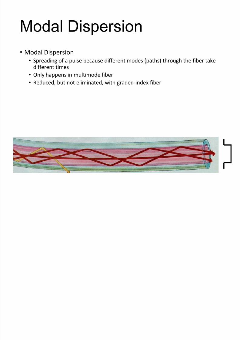
Modal Dispersion
• Modal Dispersion
• Spreading of a pulse because different modes (paths) through the fiber takedifferent times
• Only happens in multimode fiber
• Reduced, but not eliminated, with graded-index fiber

8/13/2019 Fibre Plus Dispersion
http://slidepdf.com/reader/full/fibre-plus-dispersion 80/89
Chromatic Dispersion
• Different wavelengths travel at different speeds through the fiber
• This spreads a pulse in an effect named chromatic dispersion
• Chromatic dispersion occurs in both singlemode and multimode fiber
• Larger effect with LEDs than with lasers
• A far smaller effect than modal dispersion

8/13/2019 Fibre Plus Dispersion
http://slidepdf.com/reader/full/fibre-plus-dispersion 81/89
Polarization Mode Dispersion
• Light with different polarization can travel at different speeds, if the fiberis not perfectly symmetric at the atomic level
• This could come from imperfect circular geometry or stress on the cable,and there is no easy way to correct it
• It can affect both singlemode and multimode fiber.

8/13/2019 Fibre Plus Dispersion
http://slidepdf.com/reader/full/fibre-plus-dispersion 82/89
Modal Distribution
• In graded-index fiber, the off-axis modes go a longer distance thanthe axial mode, but they travel faster, compensating for dispersion
• But because the off-axis modes travel further, they suffer more attenuation

8/13/2019 Fibre Plus Dispersion
http://slidepdf.com/reader/full/fibre-plus-dispersion 83/89
Equilibrium Modal Distribution
• A long fiber that has lost the high-order modes is said to have anequilibrium modal distribution
• For testing fibers, devices can be used to condition the modaldistribution so measurements will be accurate

8/13/2019 Fibre Plus Dispersion
http://slidepdf.com/reader/full/fibre-plus-dispersion 84/89
Mode Stripper
• An index-matching substance is put on the outside of the fiber toremove light travelling through the cladding
• Figure from fiber-optics.info (Link Ch 2o)

8/13/2019 Fibre Plus Dispersion
http://slidepdf.com/reader/full/fibre-plus-dispersion 85/89
Mode Scrambler
• Mode scramblers mix light to excite every possible mode oftransmission within the fiber
• Used for accurate measurements of attenuation
• Figure fromfiber-optics.info(Link Ch 2o)
8/13/2019 Fibre Plus Dispersion
http://slidepdf.com/reader/full/fibre-plus-dispersion 86/89
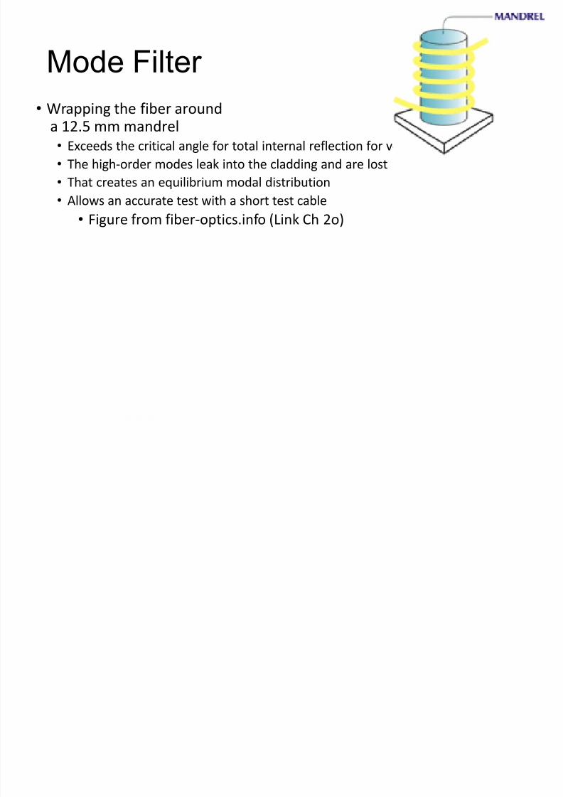
Mode Filter
• Wrapping the fiber arounda 12.5 mm mandrel
• Exceeds the critical angle for total internal reflection for very oblique modes
• The high-order modes leak into the cladding and are lost
• That creates an equilibrium modal distribution
• Allows an accurate test with a short test cable• Figure from fiber-optics.info (Link Ch 2o)

8/13/2019 Fibre Plus Dispersion
http://slidepdf.com/reader/full/fibre-plus-dispersion 87/89
Decibel Units

8/13/2019 Fibre Plus Dispersion
http://slidepdf.com/reader/full/fibre-plus-dispersion 88/89
Optical Loss in dB (decibels)
• If the data link is perfect, and loses no power
• The loss is 0 dB
• If the data link loses 50% of the power• The loss is 3 dB, or a change of – 3 dB
• If the data link loses 90% of the power
• The loss is 10 dB, or a change of – 10 dB
• If the data link loses 99% of the power
• The loss is 20 dB, or a change of – 20 dB
dB = 10 log (Power Out / Power In)
Data LinkPower In Power Out

8/13/2019 Fibre Plus Dispersion
http://slidepdf.com/reader/full/fibre-plus-dispersion 89/89
Absolute Power in dBm
• The power of a light is measured in milliwatts
• For convenience, we use the dBm units, where-20 dBm = 0.01 milliwatt
-10 dBm = 0.1 milliwatt0 dBm = 1 milliwatt
10 dBm = 10 milliwatts
20 dBm = 100 milliwatts