high performance fibre reinforced concrete: … words: steel fibre, tension, dispersion,...
TRANSCRIPT
VIII International Conference on Fracture Mechanics of Concrete and Concrete Structures
FraMCoS-8 J.G.M. Van Mier, G. Ruiz, C. Andrade, R.C. Yu and X.X. Zhang (Eds)
1
HIGH PERFORMANCE FIBRE REINFORCED CONCRETE: FUNDAMENTAL
BEHAVIOUR AND MODELLING
STEPHEN J. FOSTER*, TREVOR HTUT
† AND TIAN SING NG
*
* The University of New South Wales, School of Civil and Environmental Engineering
Centre for Infrastructure Engineering and Safety, Sydney, Australia
e-mail: [email protected] - Web page: http://www2.civeng.unsw.edu.au/staffinfo/stephen_foster/
†
Sinclair Knight Merz, Adelaide, South Australia
e-mail: [email protected]
Key words: Steel fibre, tension, dispersion, distribution, X-ray, imaging, concrete, modelling.
Abstract: This paper reports on the results of X-ray imaging of steel fibre reinforced concrete in
tension. The observations on fundamental behaviour and influences in the development of models
for structural design are discussed. It is observed that crack paths find ways of least resistance
through a section and divert around fibre ends, where possible. In large scale structural members
where crack locations are not fixed by either geometry or load state, variability in fibre dispersion
should be considered at the model level, rather than incorporated in materials or member safety
factors. Based on image analysis, the fibre dispersion influence factor is quantified for the case
where multiple cracking paths may occur.
1 INTRODUCTION
By 3000 BC the Egyptians had used a
combination of lime and gypsum mortar as
binding agents in their construction of the
Pyramids. In latter period of the Roman
Republic, the Romans of southern Italy mixed
a volcanic sand, pozzuolana, found near
Pozzuoli on the Bay of Naples to form a
hydraulic-setting cement paste. This mixed
with aggregate gave rise to Roman concrete
with good compressive strength properties,
which was used together with complex
structural shapes such as domes and arches.
One of the first uses of hydraulic-setting
cement was in 27 BC for the dome of the
Pantheon. At around the 2nd
century BC, the
Chinese used cementitious materials in the
Great Wall of China. Thus, while early
concrete technologies were available, this type
of concrete was not used elsewhere and stone
and brick masonry remained the dominant
construction materials for many centuries.
The modern use of concrete can be traced to
John Smeaton who, born in 1724, is famous
for his work on the Eddystone Lighthouse in
Cornwall, England, which he had been
commissioned to rebuild in 1756. Smeaton
used interlocking courses of masonry bound
with a pozzolanic mortar. In his later work, he
added aggregate to the mix and built Ramsgate
Harbour, Perth, and Coldstream Bridges and
the Forth and Clyde Ship Canals. In the early
1850’s, the use of reinforcing steel was
introduced by Jean-Louis Lambot in his boats.
In 1889, the first concrete reinforced bridge
was built, the Alvord Lake Bridge, USA.
Basic cement tests were standardised in the
early 1900’s and in 1904, with the construction
of the Ingalls building USA, the first concrete
skyscraper was built. In 1916, the Portland
Cement Association was founded and, a year
later, the US Bureau of Standards and the
Stephen Foster, Trevor Htut and Tian Sing Ng
2
American Society for Testing Materials
(ASTM) established a standard formula for
Portland cement. Concrete construction was
set to revolutionise the building and
infrastructure construction industries.
Interest in advanced cement-based materials
sawed, not only because of their increased
strength but also due to their generally high-
performance characteristics. The earliest use of
high performance concrete (HPC) can be
traced to the 1950’s and in the time since there
has been numerous projects that have used
HPC in their construction. In 1973, Water
Tower Place reached 260 metres with concrete
strengths as high as 60 MPa and in the
following two to three decades, high
performance concrete became widely used in
bridge and high rise building construction.
In the early 1960's, pioneering research into
fibre reinforced concrete was undertaken by
Romualdi and Batson [1] where it was
demonstrated that the tensile strength and
crack resistance of concrete can be improved
by providing suitably arranged, closely spaced,
wire reinforcement. After 50 years of research
in the development and placement of fibres in
reinforced concrete, the concept has matured
to the stage where it is finding increasing use
in practice. The materials used for fibres have
also seen significant advancements including
stainless steels and complex polymers. As
early as 1994, Banthia and Trottier [2]
recorded that fibres are used as a form of shear
reinforcement in reinforced concrete (RC)
structural elements, for blast resistance in
structures, as shotcrete in tunnel linings, for
use in slope stabilisation works and to limit
early age shrinkage cracking in large concrete
pavements.
By adding fibres to a concrete mix the
objective is to bridge discrete cracks providing
for some control to the fracture process and
increase the fracture energy. Since the early
work, the pullout mechanism of discontinuous
fibres embedded in a variety of cementitious
materials has been studied by a number of
researchers [3-13].
The current understanding of the behaviour
of fibre-matrix interfacial mechanics is based
on a number of pullout studies using single or
multiple fibres where steel fibres are
embedded within a cementitious matrix. The
experimental parameters investigated include
the rate of loading [14-16], curing and
environmental temperatures [2, 17, 18], the
quantity and quality of the matrix [19-21],
addition of adhesive agents [22] and fibre type
and fibre orientation [2, 23, 24]. In spite of a
belief sometimes expressed [2] that no
correlation exists between the behaviour of a
single fibre pullout test and the behaviour of
bulk fibres in a real composite matrix, the
effectiveness of a fibres as a medium of stress
transfer is often assessed using fibre pullout
tests where slip between the fibres and the
matrix is monitored as a function of the
applied load.
2 OBSERVATIONS FROM X-RAY
IMAGING
Htut [25] conducted X-ray imaging on
seven dog-bone shaped specimens subjected to
uniaxial tension. It was observed that the crack
initiation is likely to commence at the point of
minimum resistance and, consequently, cracks
initiate from the location at which least
number of fibres are located; that is, cracks
initiate from areas with poor fibre dispersion
rather than at the narrowest part of the dog-
bone specimen. Thus, fibre dispersion plays a
significant role in crack initiation and,
consequently, on the tensile strength.
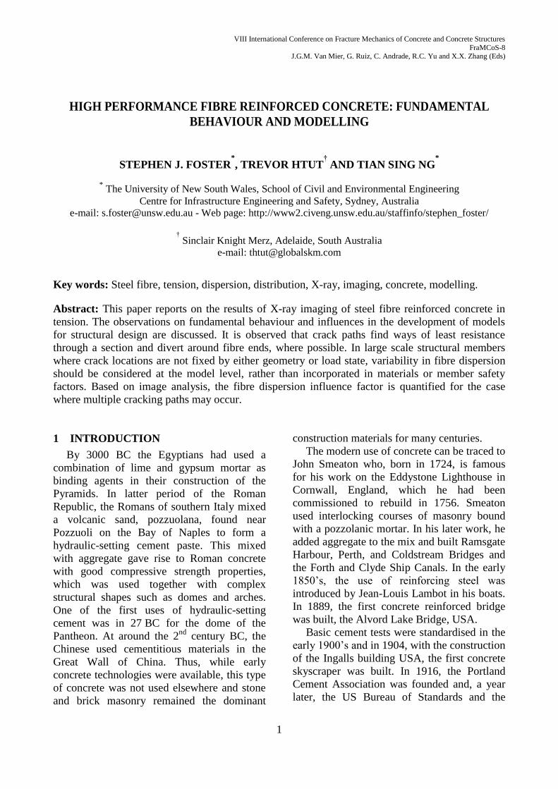
As was observed by Markovic et al. [26],
the crack path follows the easiest propagation
route and is often near the end of fibres or
around them (Figures 1 and 2). Consequently,
many of the end-hooked fibres fail to engage
and do not deform during the fracture process.
3. FIBRE DISPERSION
The dispersion of fibres in the matrix and
deformation of the end-hooks significantly
influences the tensile behaviour of a SFRC
composite. In the development of material
models for design, this observation needs
consideration. By digitalising X-ray images of
specimens we may learn more on fibre
dispersion and distribution. Eleven 30 mm
thick dog-bone shaped specimens with
Stephen Foster, Trevor Htut and Tian Sing Ng
3
randomly distributed 25 mm long by 0.3 mm
diameter end hooked fibres and volume
percentages of between 0.5% and 2% were
cast and X-ray imaged prior to tensile testing.
The images were then analysed for fibre
concentration over various regions (Figure 3);
to avoid the wall effect in the analyses, the
region near the side walls was excluded.
(a)
(b) Figure 1: X-ray images showing crack formation during
a uniaxial tension test: (a) 0.5% fibres; (b) 1.5% fibres.
Figure 2: Crack propagation during a uniaxial
tension test: (a) 0.5% fibres.
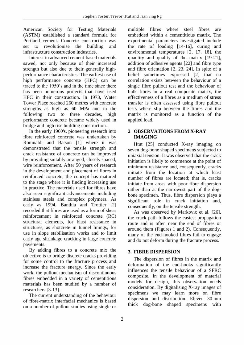
The digital image analysis was undertaken
using IMAQTM
Vision Builder software. Each
sample image was filtered to distinguish the
fibres from the background image (Figure 4).
A particle analysis was then undertaken to
determine the area of fibres in the image
(white area in Figure 4b) with the fibre
dispersion/distribution factor (Ffd) defined as
the ratio of white area to the total sample area.
Only a limited improvement in result of the
analysis (approximately 2%) was observed
when the sampling size was reduced much
below the length of the fibres and a sampling
size of 25 mm 25 mm was adopted for
further investigation. The dispersion results are
presented in Figure 5.
(a)
(b)
Figure 3: Sampling locations for fibre dispersion
analysis: (a) 12.5 mm 12.5 mm; (b) 25 mm 25 mm.
(a)
(b) Figure 4: Example of 50 mm square sample; (a)
original image before filtering and colour inversion, and
(b) digital image after filtering.
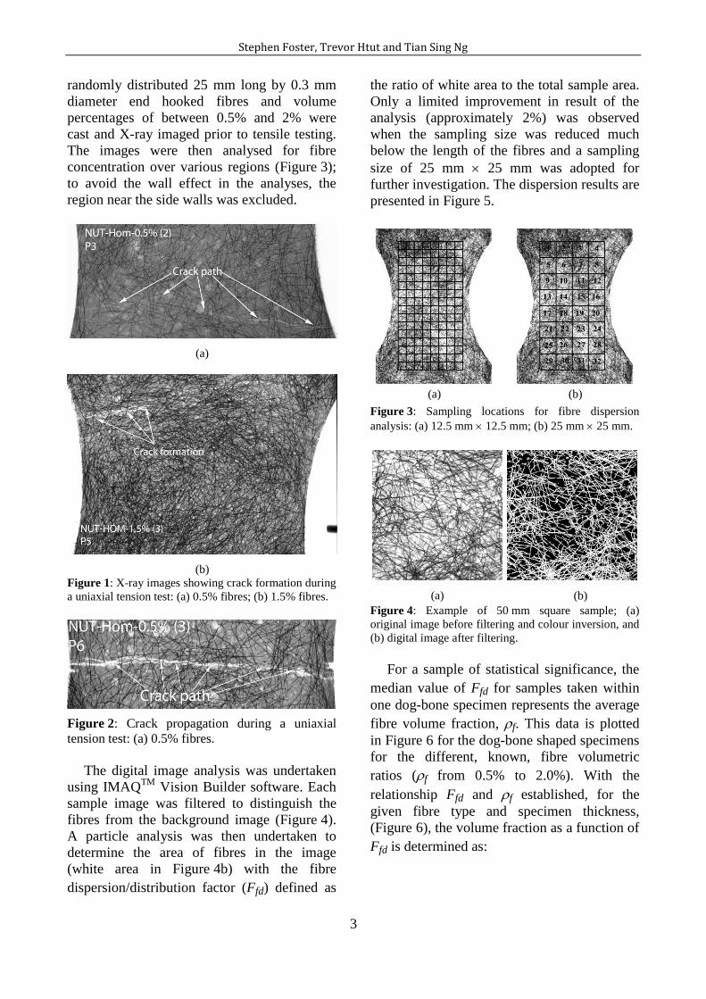
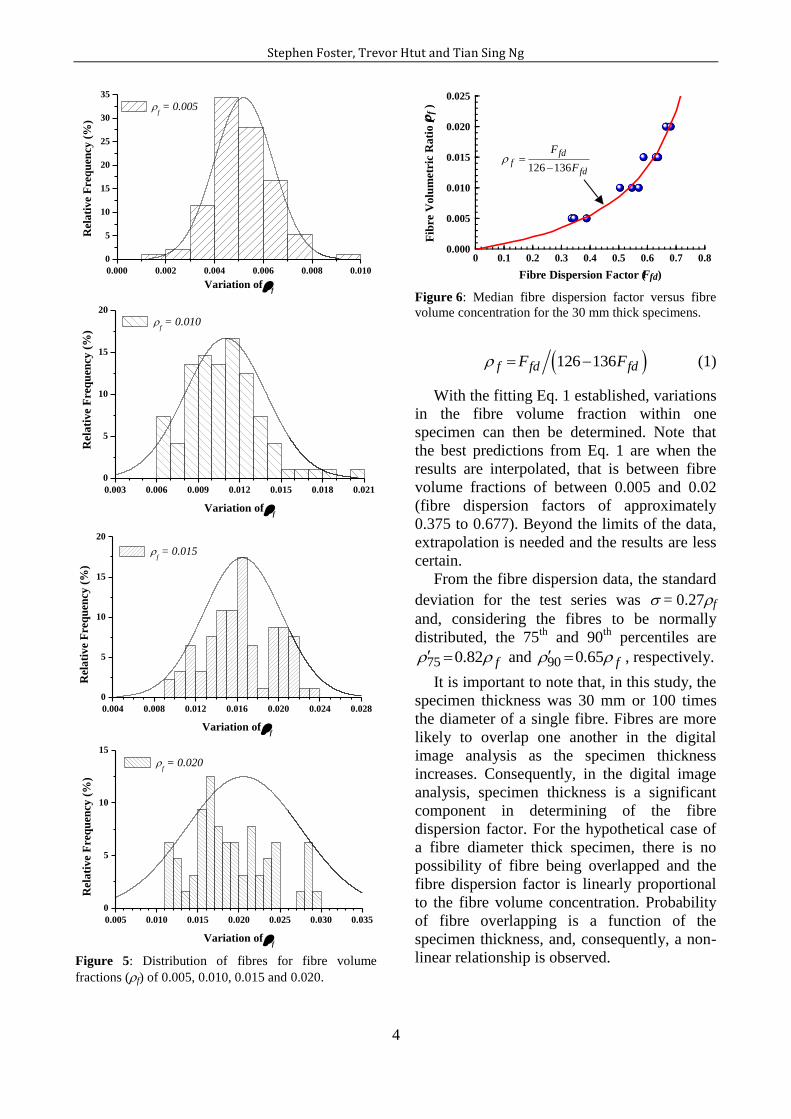
For a sample of statistical significance, the
median value of Ffd for samples taken within
one dog-bone specimen represents the average
fibre volume fraction, f. This data is plotted
in Figure 6 for the dog-bone shaped specimens
for the different, known, fibre volumetric
ratios (f from 0.5% to 2.0%). With the
relationship Ffd and f established, for the
given fibre type and specimen thickness,
(Figure 6), the volume fraction as a function of
Ffd is determined as:
Stephen Foster, Trevor Htut and Tian Sing Ng
4
0.000 0.002 0.004 0.006 0.008 0.010
0
5
10
15
20
25
30
35R
ela
tiv
e F
req
uen
cy (
%)
Variation of f
f = 0.005
0.003 0.006 0.009 0.012 0.015 0.018 0.021
0
5
10
15
20
Rel
ati
ve
Fre
qu
ency
(%
)
Variation of f
f = 0.010
0.004 0.008 0.012 0.016 0.020 0.024 0.028
0
5
10
15
20
Rel
ati
ve
Fre
qu
ency
(%
)
Variation of f
f = 0.015
0.005 0.010 0.015 0.020 0.025 0.030 0.035
0
5
10
15
Rel
ati
ve
Fre
qu
ency
(%
)
Variation of f
f = 0.020
0.000 0.002 0.004 0.006 0.008 0.010
0
5
10
15
20
25
30
35
Rel
ati
ve
Fre
qu
ency
(%
)
Variation of f
f = 0.005
0.003 0.006 0.009 0.012 0.015 0.018 0.021
0
5
10
15
20
Rel
ati
ve
Fre
qu
ency
(%
)
Variation of f
f = 0.010
0.004 0.008 0.012 0.016 0.020 0.024 0.028
0
5
10
15
20
Rel
ati
ve
Fre
qu
ency
(%
)
Variation of f
f = 0.015
0.005 0.010 0.015 0.020 0.025 0.030 0.035
0
5
10
15
Rel
ati
ve
Fre
qu
ency
(%
)
Variation of f
f = 0.020
Figure 5: Distribution of fibres for fibre volume
fractions (f) of 0.005, 0.010, 0.015 and 0.020.
0 0.1 0.2 0.3 0.4 0.5 0.6 0.7 0.8
Fibre Dispersion Factor (Ffd)
0.000
0.005
0.010
0.015
0.020
0.025
Fib
re V
olu
met
ric
Rati
o (
f )
126 136
fdf
fd
F
F
Figure 6: Median fibre dispersion factor versus fibre
volume concentration for the 30 mm thick specimens.
126 136f fd fdF F (1)
With the fitting Eq. 1 established, variations
in the fibre volume fraction within one
specimen can then be determined. Note that
the best predictions from Eq. 1 are when the
results are interpolated, that is between fibre
volume fractions of between 0.005 and 0.02
(fibre dispersion factors of approximately
0.375 to 0.677). Beyond the limits of the data,
extrapolation is needed and the results are less
certain.
From the fibre dispersion data, the standard
deviation for the test series was = 0.27f
and, considering the fibres to be normally
distributed, the 75th
and 90th
percentiles are
75 0.82 f and 90 0.65 f , respectively.
It is important to note that, in this study, the
specimen thickness was 30 mm or 100 times
the diameter of a single fibre. Fibres are more
likely to overlap one another in the digital
image analysis as the specimen thickness
increases. Consequently, in the digital image
analysis, specimen thickness is a significant
component in determining of the fibre
dispersion factor. For the hypothetical case of
a fibre diameter thick specimen, there is no
possibility of fibre being overlapped and the
fibre dispersion factor is linearly proportional
to the fibre volume concentration. Probability
of fibre overlapping is a function of the
specimen thickness, and, consequently, a non-
linear relationship is observed.

VIII International Conference on Fracture Mechanics of Concrete and Concrete Structures
FraMCoS-8 J.G.M. Van Mier, G. Ruiz, C. Andrade, R.C. Yu and X.X. Zhang (Eds)
5
(a)
(b)
Figure 7: Digital X-ray image along the crack path: (a) before the image analysis and (b) after the image analysis.
4. INFLUENCE OF FIBRE DISPERSION
ON FRACTURE PROCESS
The digitised X-ray images taken during the
tension test of the dog-bone specimens show
the importance of fibre dispersion on the crack
formation/initiation and propagation processes.
To validate the findings presented in Section 3,
further digital image analysis was undertaken
to determine the fibre dispersion along the
crack path of the specimens containing fibre
volume concentrations of 0.5%, 1.0% and
1.5%. A typical X-ray image around the crack
path is shown in Figure 7a. Digital image
analysis was undertaken on a sample size of
12.5 mm square (Figure 7b) and the fibre
volume ratio versus fibre dispersion ratio is
plotted in Figure 8.
The results show that the cracks are likely
to form or propagate along the path of least
resistance. The fibre volume concentration
along the crack path was found to average
through the 75th
percentile characteristic value.
This confirms the conclusion that fibre
dispersion contributes significantly to the
fracture process in uniaxial tension and this
observation needs to be taken into
consideration during the development of
behavioural models.
0 0.1 0.2 0.3 0.4 0.5 0.6 0.7 0.8
Fibre Dispersion Factor (Ffd)
0.000
0.005
0.010
0.015
0.020
0.025
Fib
re V
olu
met
ric
Rati
o (
f ) Eq. 1
75th percentile
90th percentile
Figure 8: Fibre volume concentration ratio versus
average fibre dispersion along the crack path.
5. INFLUENCE OF FIBRE DISPERSION
ON MODELLING
Despite numerous publications on fibre
reinforced concrete behaviour, limited
research has been undertaken on developing
general design models for fibre reinforced
composites in tension. Visalvanich and
Naaman [27] derived a semi-empirical model
for the tension-softening curve in
discontinuous randomly distributed steel fibre-
reinforced mortar by assuming a purely
frictional fibre-matrix interface and complete
fibre pullout. With the same assumptions and
taking into account an additional frictional

Stephen Foster, Trevor Htut and Tian Sing Ng
6
effect called the snubbing effect, Li [13]
derived an analytical model named the fibre
pullout model (FPM) that predicts the bridging
stress-COD relationship for fibre reinforced
brittle-matrix composite.
A micro-mechanical model known as the
fibre pullout and rupture model (FPRM) was
developed by Maalej et al. [28]. In their
model, the FPM model of Li [13] was
extended to account for the possibility of fibre
rupture in the composite. The model is able to
predict the composite bridging stress-COD
relationship, account for fibre pullout, fibre
rupture and the local frictional effect or
snubbing.
Using the "fibre-matrix misfit" theory of
Timoshenko [29], Naaman et al. [30] proposed
an analytical model for straight, undeformed,
circular steel fibres aligned perpendicularly to
the cracking plane. The model was shown to
capture the pullout-slip relationship between
steel fibres and concrete when compared to the
experimental data as published by the authors.
However, this model is limited for use in
directionally orientated plain fibre composites.
Gilles [31] developed a micro-mechanical
model taking into account the different
phenomena observed during pullout of a
deformed fibre, including the interfacial
adhesion between the fibre and the matrix,
friction and fibre deformation. The model can
be used for predicting pullout behaviour of
fibres having various geometries but is limited
to the case where the fibres are aligned
perpendicular to the cracking plane.
Marti et al. [32] developed a simple
parabolic model to describe the stress-COD
relationship of randomly orientated fibre
reinforced composites where it was assumed
that, after cracking of the matrix, there is zero
contribution to tensile strength from the
matrix, the fibre pulls out from the shorter
embedded length and that the bond-shear
stress is constant along this length.
Many other models have been proposed [1,
33-39] but these models are generally limited
in their use as tools for structural designers due
to limitations of the models or due to the
complexity of the models.
In 2003/2004, the first form of the Variable
Engagement Model (VEM) was published by
Voo and Foster [40-41]. The model has since
been used as the basis for the design of RPC
and SFRC members for shear [42-45], for
punching shear in SFRC slab-column
connections [46] and as a constitutive model
for FEM [47].
Since 2003, considerable progress has been
made in development of generic models for
SFRC, including that of Lee et al [48] and the
Unified Variable Engagement Model (UVEM)
of Ng et al [49].
Model development can be placed in one of
three categories: (i) those based on
observations from direct tensile tests; (ii) those
based on observations from indirect tests, such
as that of di Prisco et al. [50]; (iii) physical-
mechanical models built from lower order
observations such as discrete fibre pull-out
testing. In each case these models require
validation against a wide range of direct
tensile test data for different fibre types and
volumes and varying matrix compositions.
This is problematic as there is yet to be an
agreed direct tensile test of standard
configuration and boundary conditions.
For models based on direct tensile testing of
unnotched specimens of reasonable size, the
influence of fibre dispersion is directly
considered. That is the dominant crack forms
where the local fibre concentration is at its
lowest across a section and where near the end
of a fibre, deflects around it. This was clearly
evident in the X-ray images of Htut [25].
When specimens have a dominant notch,
however, the crack path forms at the notch and
the impact of fibre dispersion is negated [26].
Consequently, fibres have a higher possibility
of being fully deformed in the notched section
tests and, thus, higher tensile strengths and
ductility are observed. On the other hand, if
the notch is not dominant, failure may occur
away from the notch at a section where low
fibre numbers, through dispersion variations,
occur. As a part of his testing programme, Htut
[25] undertook tension tests on three 120 mm
wide by 30 mm thick dog-bone shaped
specimen that had a pair of 5 mm notches at
the critical section, reducing the cross-
Stephen Foster, Trevor Htut and Tian Sing Ng
7
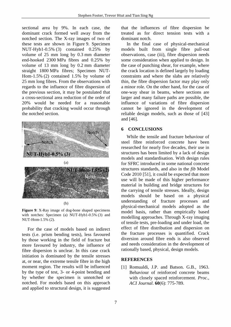
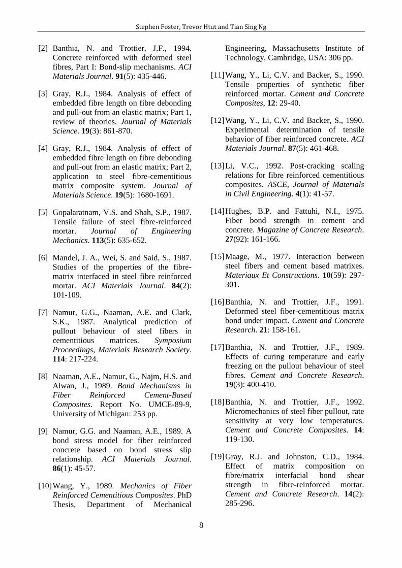
sectional area by 9%. In each case, the
dominant crack formed well away from the
notched section. The X-ray images of two of
these tests are shown in Figure 9. Specimen
NUT-Hyb1-0.5% (3) contained 0.25% by
volume of 25 mm long by 0.3 mm diameter
end-hooked 2300 MPa fibres and 0.25% by
volume of 13 mm long by 0.2 mm diameter
straight 1800 MPa fibres; Specimen NUT-
Hom-1.5% (2) contained 1.5% by volume of
25 mm long fibres. From the observations with
regards to the influence of fibre dispersion of
the previous section, it may be postulated that
a cross-sectional area reduction of the order of
20% would be needed for a reasonable
probability that cracking would occur through
the notched section.
(a)
(b)
Figure 9: X-Ray image of dog-bone shaped specimens
with notches: Specimen (a) NUT-Hyb1-0.5% (3) and
NUT-Hom-1.5% (2).
For the case of models based on indirect
tests (i.e. prism bending tests), less favoured
by those working in the field of fracture but
more favoured by industry, the influence of
fibre dispersion is unclear. In this case crack
initiation is dominated by the tensile stresses
at, or near, the extreme tensile fibre in the high
moment region. The results will be influenced
by the type of test, 3- or 4-point bending and
by whether the specimen is unnotched or
notched. For models based on this approach
and applied to structural design, it is suggested
that the influences of fibre dispersion be
treated as for direct tension tests with a
dominant notch.
In the final case of physical-mechanical
models built from single fibre pull-out
observations, case (iii), fibre dispersion needs
some consideration when applied to design. In
the case of punching shear, for example, where
the crack location is defined largely by loading
constraints and where the slabs are relatively
thin, the fibre dispersion factor may play only
a minor role. On the other hand, for the case of
one-way shear in beams, where sections are
larger and many failure paths are possible, the
influence of variations of fibre dispersion
cannot be ignored in the development of
reliable design models, such as those of [43]
and [46].
6 CONCLUSIONS
While the tensile and fracture behaviour of
steel fibre reinforced concrete have been
researched for nearly five decades, their use in
structures has been limited by a lack of design
models and standardisation. With design rules
for SFRC introduced in some national concrete
structures standards, and also in the fib Model
Code 2010 [51], it could be expected that more
use will be made of this higher performance
material in building and bridge structures for
the carrying of tensile stresses. Ideally, design
models should be based on a physical
understanding of fracture processes and
physical-mechanical models adopted as the
model basis, rather than empirically based
modelling approaches. Through X-ray imaging
of tensile tests, pre-loading and under load, the
effect of fibre distribution and dispersion on
the fracture processes is quantified. Crack
diversion around fibre ends is also observed
and needs consideration in the development of
rationally based, physical, design models.
REFERENCES
[1] Romualdi, J.P. and Batson. G.B., 1963.
Behaviour of reinforced concrete beams
with closely spaced reinforcement. Proc.,
ACI Journal. 60(6): 775-789.
Stephen Foster, Trevor Htut and Tian Sing Ng
8
[2] Banthia, N. and Trottier, J.F., 1994.
Concrete reinforced with deformed steel
fibres, Part I: Bond-slip mechanisms. ACI
Materials Journal. 91(5): 435-446.
[3] Gray, R.J., 1984. Analysis of effect of
embedded fibre length on fibre debonding
and pull-out from an elastic matrix; Part 1,
review of theories. Journal of Materials
Science. 19(3): 861-870.
[4] Gray, R.J., 1984. Analysis of effect of
embedded fibre length on fibre debonding
and pull-out from an elastic matrix; Part 2,
application to steel fibre-cementitious
matrix composite system. Journal of
Materials Science. 19(5): 1680-1691.
[5] Gopalaratnam, V.S. and Shah, S.P., 1987.
Tensile failure of steel fibre-reinforced
mortar. Journal of Engineering
Mechanics. 113(5): 635-652.
[6] Mandel, J. A., Wei, S. and Said, S., 1987.
Studies of the properties of the fibre-
matrix interfaced in steel fibre reinforced
mortar. ACI Materials Journal. 84(2):
101-109.
[7] Namur, G.G., Naaman, A.E. and Clark,
S.K., 1987. Analytical prediction of
pullout behaviour of steel fibers in
cementitious matrices. Symposium
Proceedings, Materials Research Society.
114: 217-224.
[8] Naaman, A.E., Namur, G., Najm, H.S. and
Alwan, J., 1989. Bond Mechanisms in
Fiber Reinforced Cement-Based
Composites. Report No. UMCE-89-9,
University of Michigan: 253 pp.
[9] Namur, G.G. and Naaman, A.E., 1989. A
bond stress model for fiber reinforced
concrete based on bond stress slip
relationship. ACI Materials Journal.
86(1): 45-57.
[10] Wang, Y., 1989. Mechanics of Fiber
Reinforced Cementitious Composites. PhD
Thesis, Department of Mechanical
Engineering, Massachusetts Institute of
Technology, Cambridge, USA: 306 pp.
[11] Wang, Y., Li, C.V. and Backer, S., 1990.
Tensile properties of synthetic fiber
reinforced mortar. Cement and Concrete
Composites, 12: 29-40.
[12] Wang, Y., Li, C.V. and Backer, S., 1990.
Experimental determination of tensile
behavior of fiber reinforced concrete. ACI
Materials Journal. 87(5): 461-468.
[13] Li, V.C., 1992. Post-cracking scaling
relations for fibre reinforced cementitious
composites. ASCE, Journal of Materials
in Civil Engineering. 4(1): 41-57.
[14] Hughes, B.P. and Fattuhi, N.I., 1975.
Fiber bond strength in cement and
concrete. Magazine of Concrete Research.
27(92): 161-166.
[15] Maage, M., 1977. Interaction between
steel fibers and cement based matrixes.
Materiaux Et Constructions. 10(59): 297-
301.
[16] Banthia, N. and Trottier, J.F., 1991.
Deformed steel fiber-cementitious matrix
bond under impact. Cement and Concrete
Research. 21: 158-161.
[17] Banthia, N. and Trottier, J.F., 1989.
Effects of curing temperature and early
freezing on the pullout behaviour of steel
fibres. Cement and Concrete Research.
19(3): 400-410.
[18] Banthia, N. and Trottier, J.F., 1992.
Micromechanics of steel fiber pullout, rate
sensitivity at very low temperatures.
Cement and Concrete Composites. 14:
119-130.
[19] Gray, R.J. and Johnston, C.D., 1984.
Effect of matrix composition on
fibre/matrix interfacial bond shear
strength in fibre-reinforced mortar.
Cement and Concrete Research. 14(2):
285-296.

Stephen Foster, Trevor Htut and Tian Sing Ng
9
[20] Banthia, N. and Trottier, J.F., 1989.
Effects of curing temperature and early
freezing on pull-out resistance of steel
fibers from a cementitious matrix. Cement
and Concrete Research. 19(5): 727-736.
[21] Gopalaratnam, V.S. and Abu-Mathkour,
H.J., 1987. “Investigation of the pullout
characteristics of steel fibres from mortar
matrices”. International Symposium on
Fibre Reinforced Concrete: 201-211.
[22] Guerrero, P. and Naaman, A.E., 2000.
Effect of mortar fineness and adhesive
agents on pullout response of steel fibres.
ACI Materials Journal. 97(1): 12-20.
[23] Naaman, A.E. and Shah, S.P., 1976.
Pullout mechanism in steel fibre-
reinforced concrete. ASCE, Journal of the
Structurel Division. 102(8): 1537-1548.
[24] Soroushian, P. and Bayasi, Z., 1991.
Fiber-type effects on the performance of
steel fiber reinforced concrete. ACI
Materials Journal. 88(2): 129-145.
[25] Htut, T.N.S., 2010. Fracture Processes in
Steel Fibre Reinforced Concrete. PhD
Thesis, School of Civil and Environmental
Engineeering, The University of New
South Wales: 389pp.
[26] Markovic, I., Walraven, J.C. and Van
Mier, J.G.M., 2004. Tensile behaviour of
high performance hybrid fibre concrete.
Proc. of the 5th Inter. Conf. on Fract.
Mech. of Conc. & Conc. Struct
(FraMCoS-5), April 12-16, 2006, Vale,
Colorado, USA: 1113-1120.
[27] Visalvanich, K. and Naaman, A.E., 1983.
Fracture model for fibre reinforced
concrete. ACI Journal Proceedings. 80(2):
128-138.
[28] Maalej, M., Li., C.V. and Hashida, T.,
1995. Effect of fiber rupture on tensile
properties of short fiber composites.
ASCE, Journal of Engineering Mechanics.
121(8): 903-913.
[29] Timoshenko, S., 1941. Strength of
Materials, MacMillan, London, U.K.
[30] Naaman, A.E., Namur, G.G., Alwan, J.M.
and Najm, H.S. (1991). Fibre pullout and
bond slip. I: analytical study. ASCE,
Journal of Structural Engineering. 117(9):
2769-2790.
[31] Gilles, C., 1999. Modeling the pullout of
wire-drawn steel fibers. Cement and
Concrete Research. 29: 1027-1037.
[32] Marti, P., Pfyl, T., Sigrit, V. and Ulaga,
T., 1999. Harmonized test procedure for
steel fibre-reinforced concrete. ACI
Materials Journal. 96(6): 676-685.
[33] Aveston, J. and Kelly, A., 1973. Theory of
multiple fracture of fibrous composites.
Journal of Materials Science. 8(3): 352-
362.
[34] Naaman, A.E., Argon, A.S. and
Moavenzadeh, F., 1973. A fracture model
for fiber reinforced cementitious
materials. Cement and Concrete Research.
3(4): 397-411.
[35] Pakotiprapha, B., Pama, R.P. and Lee,
S.L., 1974. Mechanical properties of
cement mortar with randomly oriented
short steel wires. Magazine of Concrete
Research. 26(86): 3-15.
[36] Gray, R.J., 1984. Analysis of effect of
embedded fibre length on fibre debonding
and pull-out from an elastic matrix; Part 1,
review of theories. J. Mat. Science. 19(3):
861-870.
[37] Brandt, A.M., 1985. On the optimal
direction of short metal fibers in brittle
matrix composites. J. Mat. Science. 20:
3831-41.
[38] Lim, T.Y., Paramasivam, P. and Lee, S.L.,
1987. Analytical model for tensile
behavior of steel-fiber concrete. ACI
Materials Journal. 84(4): 286-298.
Stephen Foster, Trevor Htut and Tian Sing Ng
10
[39] Easley, T.C., and Faber, K.T., 1999. Use a
crack-bridging single-fiber pullout test to
study steel fiber/cementitious matrix
composite. Journal of American Ceramic
Society. 82(12): 3513-352.
[40] Voo, J.Y.L. and Foster, S.J., 2003.
Variable Engagement Model for Fibre
Reinforced Concrete in Tension”,
UNICIV Report R-420, School of Civil
and Environmental Engineering, The
University of New South Wales, Sydney,
Australia: 86 pp.
[41] Voo, J.Y.L. and Foster, S.J., 2004. Tensile
fracture of fibre reinforced concrete:
variable engagement model”, In
Carpinteri et al (eds), Design, Assessment
and Retrofitting of RC Structures; Proc. of
the 6th Inter. Conf. on Fract. Mech. of
Conc. & Conc. Struct (FraMCoS-6), June
17-22, 2006, Catania, Italy: 875-884.
[42] Voo, Y.L, Foster, S.J. and Gilbert, R.I.,
2006. Shear strength of fiber reinforced
reactive powder concrete prestressed
girders without stirrups”, Journal of
Advanced Concrete Technology 4(1): 123-
132.
[43] Foster, S.J., 2010. Design of FRC beams
for shear using the VEM and the draft
model code approach. In fib Bulletin 57,
Recent Developments on Shear and
Punching Shear on RC and FRC
Elements. Chapter 12: 195-210.
[44] Voo Y.L., Poon W.K. and Foster, S.J.,
2010. Shear strength of steel fiber-
reinforced ultrahigh-performance concrete
beams without stirrups, ASCE, Journal of
Structural Engineering. 136(11): 1393-
1400.
[45] Spinella, N., Colajanni, P. and Recupero,
A., 2010, “Simple Plastic Model for Shear
Critical SFRC beams”, ASCE, Journal of
Structural Engineering,136(4): 390-400.
[46] Maya, L.F,. Fernández Ruiz, M., Muttoni,
A. and Foster, S.J., 2012., Punching shear
strength of steel fibre reinforced concrete
slabs, Engineering Structures. 40: 83–94.
[47] Foster, S.J., Voo, Y.L. and Chong K.T.,
2006. Analysis of steel fiber reinforced
concrete beams failing in shear: variable
engagement model”, In Lowes, L., and
Filippou (eds). Finite Element Analysis of
Reinforced Concrete Structures. ACI SP-
237, Chapter 5.
[48] Lee, S.C., Cho, J. and Vecchio, F.J., 2011.
Diverse embedment model for steel fibre
reinforced concrete in tension: model
development. ACI Materials Journal.
108(5): 516-525.
[49] Ng, T.S., Foster, S.J. and Htut T.N.S.,
2012. Fracture of Steel Fibre Reinforced
Concrete – the Unified Variable
Engagement Model. UNICIV Report R-
460, School of Civil and Environmental
Engineering, The University of New
South Wales: 107 pp.
[50] di Prisco, M., Plizzari, G. and
Vandewalle, L. 2009. Fibre reinforced
concrete: new design perspectives.
Materials and Structures. 42: 1261-1281.
[51] International Federation for Structural
Concrete (fib), Model Code 2010 – Final
Draft. Bulletin 65: 350 pp; and Bulletin
66: 370 pp.