field evaluation unit ces-fd-ap-… (unicode/multicode) en · operating instructions field...
TRANSCRIPT

EN
Operating Instructions
Field Evaluation Unit
CES-FD-AP-… (Unicode/Multicode)
Operating InstructionsField Evaluation Unit CES-FD-AP-…
2 (translation of the original operating instructions) 2116267-05-06/17
Contents
1. About this document ............................................................................................. 41.1. Scope ............................................................................................................................................4
1.2. Target group ..................................................................................................................................4
1.3. Key to symbols ...............................................................................................................................4
1.4. Supplementary documents ..............................................................................................................4
2. Correct use .......................................................................................................... 5
3. Description of the safety function .......................................................................... 6
4. Exclusion of liability and warranty ......................................................................... 6
5. General safety instructions.................................................................................... 6
6. Function ............................................................................................................... 76.1. Door monitoring output OD (optional) ...............................................................................................7
6.2. Limit-range monitoring ....................................................................................................................7
7. Mounting .............................................................................................................. 8
8. Electrical connection ............................................................................................ 98.1. Notes about ............................................................................................................................9
8.2. Safety in case of faults ....................................................................................................................9
8.3. Fuse protection for power supply ...................................................................................................10
8.4. Requirements for connection cables ...............................................................................................10
8.5. Connector assignment of field evaluation unit CES-FD-AP-… .............................................................118.5.1. Connection for the read head (M8, 3-pin) ........................................................................118.5.2. Device connection for the field evaluation unit with M12 plug connector, 5-pin ...................11
8.6. Connection ...................................................................................................................................12
8.7. Notes on operation with safe control systems .................................................................................13
8.8. Devices for direct connection to IP65 field modules.........................................................................13
9. Setup ................................................................................................................. 149.1. LED indicators ..............................................................................................................................14
9.2. Teach-in function for actuator (only for unicode evaluation) ...............................................................149.2.1. Preparing device for the teach-in operation and teaching in actuator .................................14
9.3. Commissioning (multicode only) .....................................................................................................15
9.4. Functional check ...........................................................................................................................159.4.1. Electrical function test ...................................................................................................15
10. System status table for unicode version .............................................................. 16
11. System status table for multicode version ........................................................... 17

32116267-05-06/17 (translation of the original operating instructions)
Operating InstructionsField Evaluation Unit CES-FD-AP-…
EN
12. Technical data .................................................................................................... 1812.1. Technical data for field evaluation unit CES-FD-AP-… ........................................................................18
12.1.1. Typical system times .....................................................................................................2012.2. Technical data for read head CES-A-LMN-SC ....................................................................................21
12.3. Actuator CES-A-BMB .....................................................................................................................23
12.4. Key adapter CKS ..........................................................................................................................24
13. Ordering information and accessories ................................................................. 25
14. Inspection and service ........................................................................................ 25
15. Service .............................................................................................................. 25
16. Declaration of conformity ................................................................................... 26

Operating InstructionsField Evaluation Unit CES-FD-AP-…
4 (translation of the original operating instructions) 2116267-05-06/17
1. About this document1.1. ScopeThis document is valid for Ì Field Evaluation Unit CES‑FD‑AP‑U‑01‑… (Unicode), field evaluation unit for 1 read head (order no. 119865) Ì Field Evaluation Unit CES‑FD‑AP‑M‑01‑… (Multicode), field evaluation unit for 1 read head (order no. 115534)
1.2. Target groupDesign engineers and installation planners for safety devices on machines, as well as setup and servicing staff possessing special expertise in handling safety components.
1.3. Key to symbolsSymbol/depiction Significance
Printed document
Internet
www Document is available for download at www.euchner.de
Document on CD
DANGER WARNING CAUTION
Safety precautionsDanger of death or severe injuriesWarning about possible injuriesCaution Slight injuries possible
NOTICE Important!
Notice about possible device damageImportant information
Tip Useful information
1.4. Supplementary documentsThe overall documentation for this device consists of the following documents:
Document title(document number) Contents
Safety information and maintenance CES-A…/CES-AZ/CES-FD(2109083)
Ì Basic safety information
Ì Maintenance instructions
Operating instructions(2116267) (this document)
Possibly enclosed data sheet Item-specific information about deviations or additions
Important!
Always read all documents to gain a complete overview of safe installation, setup and use of the device. The documents can be downloaded from www.EUCHNER.de. For this purpose enter the doc. no. in the search box.

52116267-05-06/17 (translation of the original operating instructions)
Operating InstructionsField Evaluation Unit CES-FD-AP-…
EN
2. Correct useField evaluation units of the series CES-FD-AP-… are used to evaluate safety-related signals from EUCHNER read heads in the field. The system can form an interlocking device without guard locking (type 4). The system meets the requirements according to EN IEC 60947-5-3. Devices with unicode evaluation possess a high coding level, devices with multicode eval-uation possess a low coding level.
The system consists of field evaluation unit, read head and actuator.
In combination with a movable safety guard and the machine control, this system prevents dangerous machine functions from occurring while the safety guard is open. A stop command is triggered if the safety guard is opened during the dangerous machine function.
This means: Ì Starting commands that cause a dangerous machine function must become active only when the safety guard is closed. Ì Opening the safety guard triggers a stop command. Ì Closing a safety guard must not cause automatic starting of a dangerous machine function. A separate start command must be issued. For exceptions, refer to EN 12100 or relevant C-standards.
Before use, a risk assessment must be performed on the machine, e.g. according to the following standards: Ì EN ISO 13849-1, Safety of machinery – Safety-related parts of control systems – Part 1: General principles for design Ì EN ISO 12100, Safety of machinery – General principles for design – Risk assessment and risk reduction Ì IEC 62061, Safety of machinery – Functional safety of safety-related electrical, electronic and programmable electronic control systems.
Correct use includes observing the relevant requirements for installation and operation, e.g. according to the following standards: Ì EN ISO 13849-1, Safety of machinery – Safety-related parts of control systems – Part 1: General principles for design Ì EN ISO 14119, Safety of machinery – Interlocking devices associated with guards – Principles for design and selection Ì EN 60204-1, Safety of machinery – Electrical equipment of machines.
The following components can be connected to the field evaluation unit CES-FD-AP-…: Ì CES read heads Ì CKS key adapter
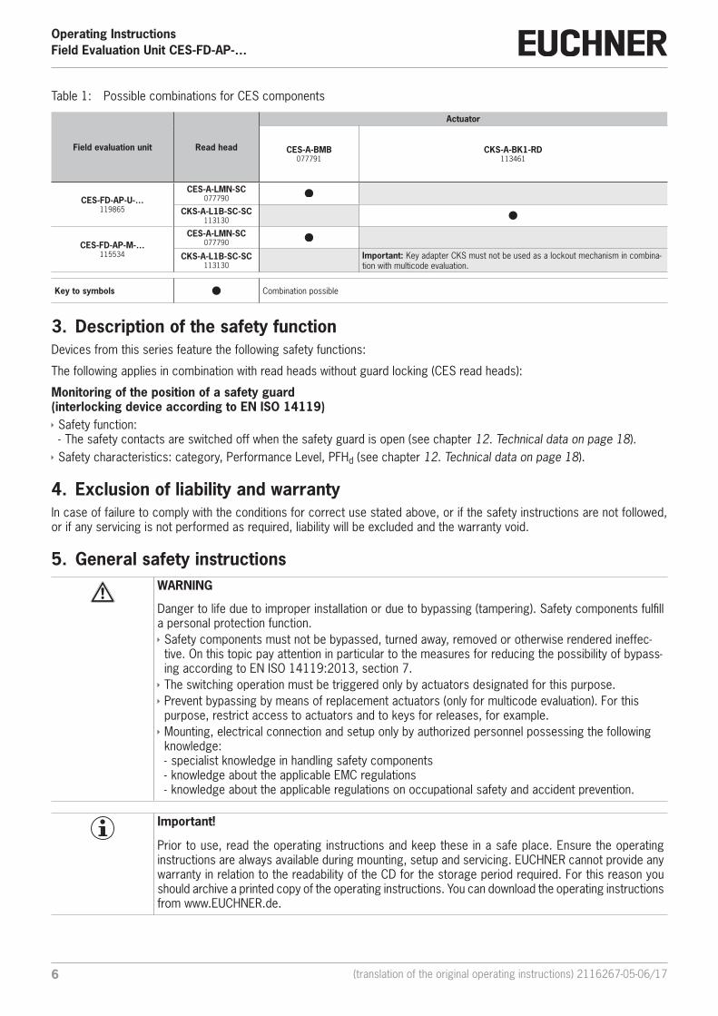
For further information, refer to the operating instructions of the corresponding component and to Table 1: Possible com‑binations for CES components on page 6.
Important!
Ì The user is responsible for the proper integration of the device into a safe overall system. For this purpose, the overall system must be validated, e.g. in accordance with EN ISO 13849-2. Ì Correct use requires observing the permissible operating parameters (see chapter 12. Technical data on page 18). Ì If a data sheet is included with the product, the information on the data sheet applies. Ì It is only allowed to use components that are permissible in accordance with the table below.
Operating InstructionsField Evaluation Unit CES-FD-AP-…
6 (translation of the original operating instructions) 2116267-05-06/17
Table 1: Possible combinations for CES components
Field evaluation unit Read head
Actuator
CES-A-BMB077791
CKS-A-BK1-RD113461
CES-FD-AP-U-…119865
CES-A-LMN-SC077790
CKS-A-L1B-SC-SC113130
CES-FD-AP-M-…115534
CES-A-LMN-SC077790
CKS-A-L1B-SC-SC113130
Important: Key adapter CKS must not be used as a lockout mechanism in combina-tion with multicode evaluation.
Key to symbols Combination possible
3. Description of the safety functionDevices from this series feature the following safety functions:
The following applies in combination with read heads without guard locking (CES read heads):
Monitoring of the position of a safety guard (interlocking device according to EN ISO 14119) Ì Safety function: - The safety contacts are switched off when the safety guard is open (see chapter 12. Technical data on page 18).
Ì Safety characteristics: category, Performance Level, PFHd (see chapter 12. Technical data on page 18).
4. Exclusion of liability and warrantyIn case of failure to comply with the conditions for correct use stated above, or if the safety instructions are not followed, or if any servicing is not performed as required, liability will be excluded and the warranty void.
5. General safety instructionsWARNING
Danger to life due to improper installation or due to bypassing (tampering). Safety components fulfill a personal protection function. Ì Safety components must not be bypassed, turned away, removed or otherwise rendered ineffec-tive. On this topic pay attention in particular to the measures for reducing the possibility of bypass-ing according to EN ISO 14119:2013, section 7. Ì The switching operation must be triggered only by actuators designated for this purpose. Ì Prevent bypassing by means of replacement actuators (only for multicode evaluation). For this purpose, restrict access to actuators and to keys for releases, for example. Ì Mounting, electrical connection and setup only by authorized personnel possessing the following knowledge: - specialist knowledge in handling safety components - knowledge about the applicable EMC regulations - knowledge about the applicable regulations on occupational safety and accident prevention.
Important!
Prior to use, read the operating instructions and keep these in a safe place. Ensure the operating instructions are always available during mounting, setup and servicing. EUCHNER cannot provide any warranty in relation to the readability of the CD for the storage period required. For this reason you should archive a printed copy of the operating instructions. You can download the operating instructions from www.EUCHNER.de.

72116267-05-06/17 (translation of the original operating instructions)
Operating InstructionsField Evaluation Unit CES-FD-AP-…
EN
6. FunctionThe safety system consists of three components: Ì Coded actuator Ì Read head Ì Field evaluation unit
One read head can be connected to the field evaluation unit.
Each delivered actuator possesses a unique electronic coding and so is a unique element in the system used. The code in an actuator cannot be reprogrammed.
Whether the device learns the complete actuator code (unicode) or not (multicode) depends on the respective version. Ì Devices with unicode evaluation: The actuator must be assigned to the safety switch by a teach-in operation so that it is detected by the system. This unambiguous assignment ensures a particularly high level of protection against tam-pering. The system thus possesses a high coding level. Ì Devices with multicode evaluation: Unlike systems with unique code detection, on multicode devices a specific code is not requested but instead it is only checked whether the actuator is of a type that can be detected by the system (multicode detection). There is no exact comparison of the actuator code with the taught-in code in the safety switch (unique code detection). The system possesses a low coding level.
The read head is fastened to the fixed part of the safety guard and is connected to the field evaluation unit via a two-core screened cable (plug X2, H1/H2 and SH).
The actuator fastened to the movable part of the safety guard is moved towards the read head by closing the door. When the switch-on distance is reached, power is supplied to the actuator by the read head by induction and data can be transferred.
If a permissible code is detected, the safety outputs are switched on.
The safety outputs are switched off when the safety guard is opened.
In the event of a fault in the safety switch, the safety outputs are switched off and the DIA LED illuminates red. The occurrence of faults is detected at the latest on the next demand to close the safety outputs (e.g. on starting).
6.1. Door monitoring output OD (optional)The door monitoring output is switched on as soon as a valid actuator is detected in the operating distance.
6.2. Limit-range monitoringIf the safety door with the actuator should settle over time, the actuator can drift out of the read head operating distance. The device recognizes this situation and indicates that the actuator is in the limit range by flashing the STATE LED. This allows the safety door to be readjusted in time. Also refer to system status tables in chapters 10 and 11.

Operating InstructionsField Evaluation Unit CES-FD-AP-…
8 (translation of the original operating instructions) 2116267-05-06/17
7. MountingNOTICE
Device damage due to improper installation or unsuitable ambient conditions. Ì Read heads and actuators must not be used as a mechanical end stop. Ì Observe EN ISO 14119:2013, sections 5.2 and 5.3, for information about fastening the safety switch and the actuator. Ì Observe EN ISO 14119:2013, section 7, for information about reducing the possibilities for by-passing an interlocking device.
Important!
Ì From the assured switch-off distance Sar, the safety outputs are safely shut down. Ì When mounting several read heads, observe the stipulated minimum distance to avoid mutual in-terference. - For CES-A-LMN smin = 20 mm
min. 20 mm
Note the following points: Ì Actuator and read head must be fitted so that - the front faces are at the minimum switch-on distance 0.8 x Sao or closer when the safety guard is closed (see section Operating distances). To avoid entering the area of possible side lobes, a minimum distance is to be maintained in case of a side approach direction. See section Typical operating distance for the related actuator.
- a hazard is excluded until the assured switch-off distance (Sar) is reached when the safety guard is open. - the actuator is positively mounted on the safety guard, e.g. by using the safety screws included. - they cannot be removed or tampered with using simple means.
Ì Pay attention to the maximum tightening torque for the field evaluation unit, read head and actuator mountings of 1 Nm.

92116267-05-06/17 (translation of the original operating instructions)
Operating InstructionsField Evaluation Unit CES-FD-AP-…
EN
8. Electrical connectionWARNING
In case of an error, loss of the safety function through incorrect connection. Ì Monitoring outputs must not be used as safety outputs. Ì Lay the connection cables with protection to prevent the risk of short circuits.
CAUTION
Risk of damage to equipment or malfunctions as a result of incorrect connection. Ì The device generates its own clock signal on the output lines FO1A/FO1B. A downstream control system must tolerate these pulses, which may have a length of up to 0.3 ms. No clock pulses are output when the safety outputs are switched off. Ì The inputs on an evaluation unit connected must be positive-switching, as the two outputs on the safety switch deliver a level of +24 V in the switched-on state. Ì All the electrical connections must either be isolated from the mains supply by a safety transformer according to IEC 61558-2-6 with limited output voltage in the event of a fault, or by other equivalent isolation measures (PELV). Ì All electrical outputs must have an adequate protective circuit for inductive loads. The outputs must be protected with a free-wheeling diode for this purpose. RC interference suppression units must not be used. Ì Power devices which are a powerful source of interference must be installed in a separate location away from the input and output circuits for signal processing. The cable routing for safety circuits should be as far away as possible from the cables of the power circuits. Ì In order to avoid EMC interference, the physical environmental and operating conditions at the installation site of the device must comply with the requirements according to the standard EN 60204-1:2006, section 4.4.2 (EMC). Ì Please pay attention to any interference fields in case of devices such as frequency converters or induction heating systems. Observe the EMC instructions in the manuals from the respective man-ufacturer.
Important!
If the device does not appear to function when operating voltage is applied (e.g. green STATE LED does not flash), the safety switch must be returned unopened to the manufacturer.
8.1. Notes about
Important!
Ì For use and operation as per the requirements1), a power supply with the feature “for use in class 2 circuits” must be used.Alternative solutions must comply with the following requirements:a) Electrically isolated power supply unit with a max. open-circuit voltage of 30 V/DC and a limited
current of max. 8 A.b) Electrically isolated power supply unit in combination with fuse as per UL248. This fuse should be
designed for max. 3.3 A and should be integrated into the 30 V DC voltage section. Ì For use and operation as per the requirements1), , a connection line, which is listed under the UL category code CYJV2, must be used.
1) Note on the scope of the UL approval: The devices are tested according to the requirements of UL508 and CSA/ C22.2 no. 14 (protection against electric shock and fire). Only for applications according to NFPA 79 (Industrial Machinery).
8.2. Safety in case of faults Ì The operating voltage UB is reverse polarity protected. Ì The safety outputs are short circuit-proof. Ì A short circuit between the safety outputs is detected by the switch. Ì A short-circuit in the cable can be excluded by laying the cable with protection.
Operating InstructionsField Evaluation Unit CES-FD-AP-…
10 (translation of the original operating instructions) 2116267-05-06/17
8.3. Fuse protection for power supplyThe power supply must be provided with fuse protection depending on the number of switches and current required for the outputs. The following rules apply:
Max. current consumption of an individual switch Imax
Imax = IUB + IOD + IFO1A+FO1B
IUB = Switch operating current (45 mA)
IOD = Load current of monitoring output (max. 50 mA)
IFO1A+FO1B = Load current of safety outputs FO1A + FO1B (2 x max. 150 mA)
8.4. Requirements for connection cables
CAUTION
Risk of damage to equipment or malfunctions as a result of incorrect connection cables. Ì Use connection components and connection cables from EUCHNER. Ì On the usage of other connection components, the requirements in the following table apply. EUCHNER provides no warranty for safe function in case of failure to comply with these require-ments. Ì The connection cable for the field evaluation unit must not be longer than 180 m in total. Ì The connection cable from the field evaluation unit to the read head is only allowed to be extended with the aid of the extension (order no. 115464). Ì The read head cable must not be longer than 0.7 m in total.
Observe the following requirements with respect to the connection cables:
Parameter Value UnitWire cross-section min. 0.14 mm²
R max. 150 W/km
C max. 120 nF/km
L max. 0.65 mH/km
Recommended cable type LIYY 8x or 5x0.1 mm²
112116267-05-06/17 (translation of the original operating instructions)
Operating InstructionsField Evaluation Unit CES-FD-AP-…
EN
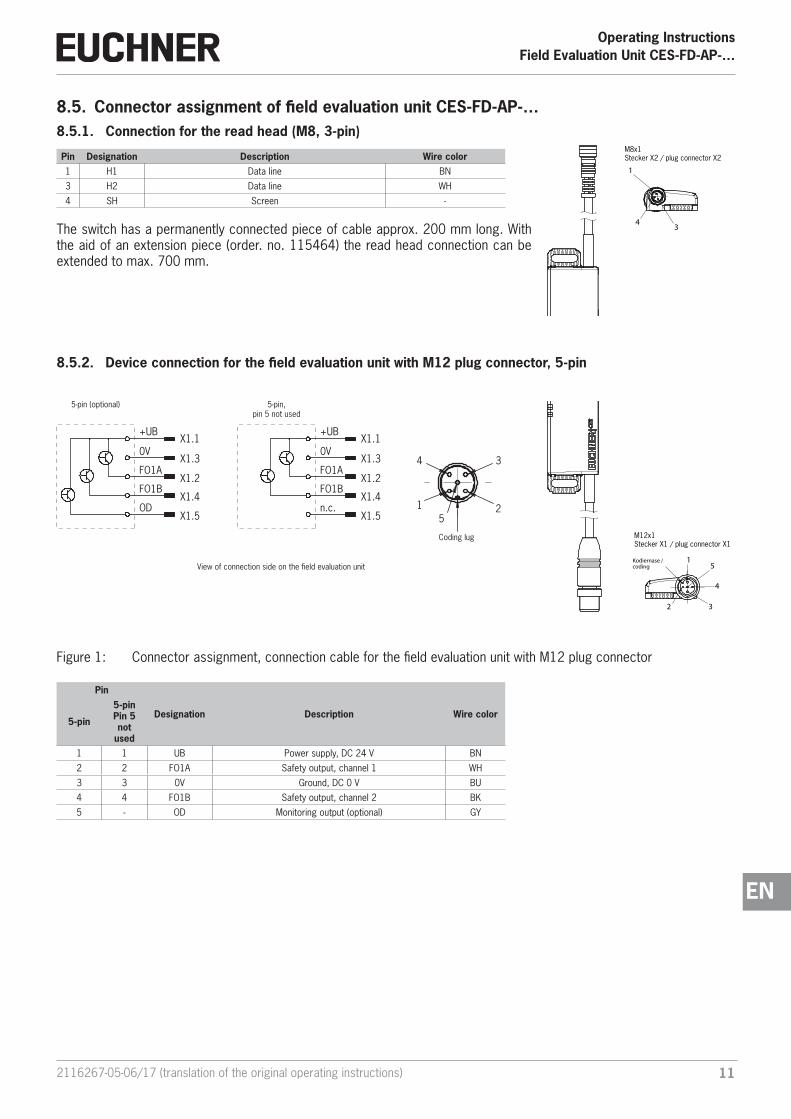
8.5. Connector assignment of field evaluation unit CES-FD-AP-…8.5.1. Connection for the read head (M8, 3-pin)
Pin Designation Description Wire color1 H1 Data line BN
3 H2 Data line WH
4 SH Screen -
The switch has a permanently connected piece of cable approx. 200 mm long. With the aid of an extension piece (order. no. 115464) the read head connection can be extended to max. 700 mm.
8.5.2. Device connection for the field evaluation unit with M12 plug connector, 5-pin
View of connection side on the field evaluation unit
X1.1
X1.3
X1.2
X1.4
X1.5
+UB
0V
FO1A
FO1B
n.c.
4
15
2
3
X1.1
X1.3
X1.2
X1.4
X1.5
+UB
0V
FO1A
FO1B
OD
Coding lug
5-pin (optional) 5-pin,pin 5 not used
M12x1Stecker X1 / plug connector X1
M8x1 Stecker X2 / plug connector X2
1
43
Kodiernase /coding
15
4
32
Figure 1: Connector assignment, connection cable for the field evaluation unit with M12 plug connector
Pin
Designation Description Wire color5-pin
5-pinPin 5not
used1 1 UB Power supply, DC 24 V BN
2 2 FO1A Safety output, channel 1 WH
3 3 0V Ground, DC 0 V BU
4 4 FO1B Safety output, channel 2 BK
5 - OD Monitoring output (optional) GY
M12x1Stecker X1 / plug connector X1
M8x1 Stecker X2 / plug connector X2
1
43
Kodiernase /coding
15
4
32
Operating InstructionsField Evaluation Unit CES-FD-AP-…
12 (translation of the original operating instructions) 2116267-05-06/17
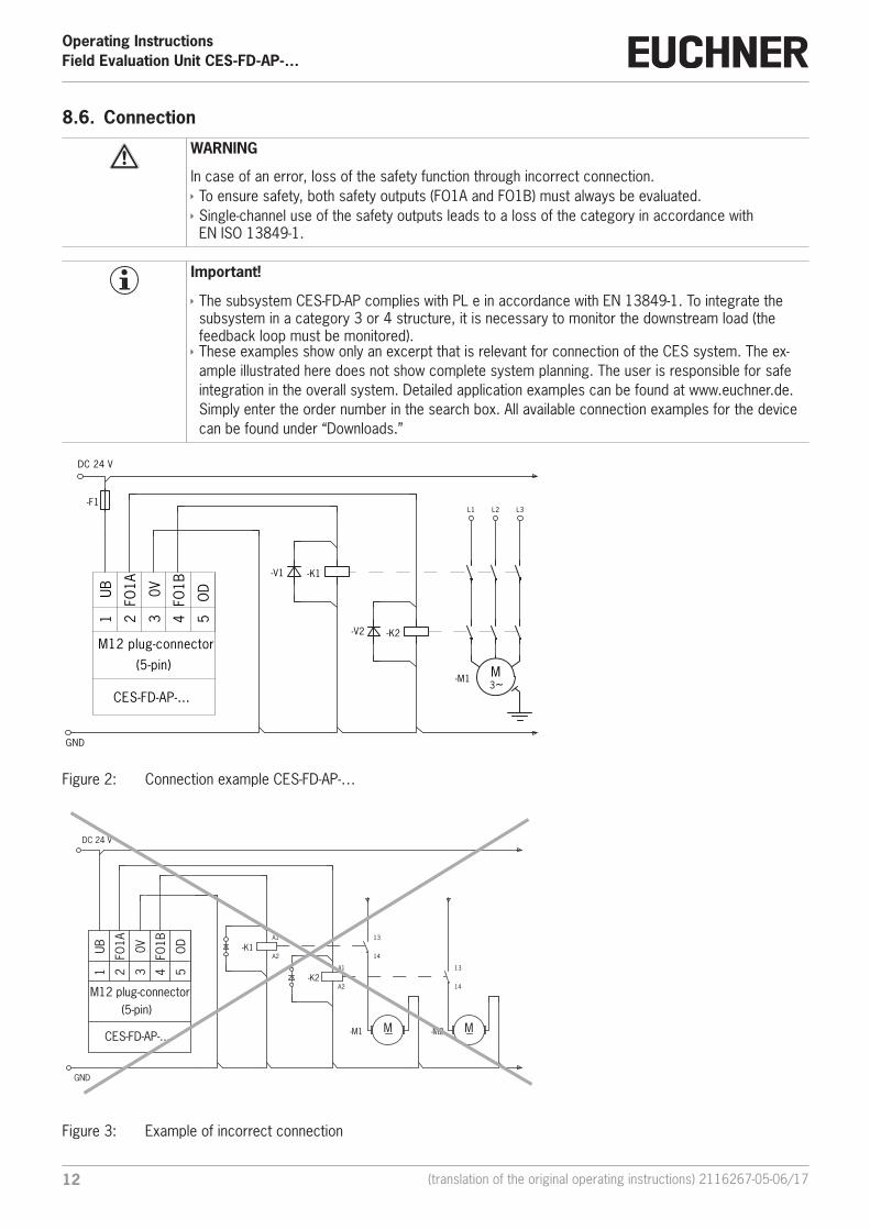
8.6. Connection
WARNING
In case of an error, loss of the safety function through incorrect connection. Ì To ensure safety, both safety outputs (FO1A and FO1B) must always be evaluated. Ì Single-channel use of the safety outputs leads to a loss of the category in accordance with EN ISO 13849-1.
Important!
Ì The subsystem CES-FD-AP complies with PL e in accordance with EN 13849-1. To integrate the subsystem in a category 3 or 4 structure, it is necessary to monitor the downstream load (the feedback loop must be monitored). Ì These examples show only an excerpt that is relevant for connection of the CES system. The ex-ample illustrated here does not show complete system planning. The user is responsible for safe integration in the overall system. Detailed application examples can be found at www.euchner.de. Simply enter the order number in the search box. All available connection examples for the device can be found under “Downloads.”
GND
DC 24 V
-F1
CES-FD-AP-...
UB1
FO1A
2
FO1B
4
M12 plug-connector
(5-pin)
OD
5
0V3
-V1 -K1
-V2 -K2
L1
M3~-M1
L2 L3
Figure 2: Connection example CES-FD-AP-…
GND
DC 24 V
CES-FD-AP-...
UB1
FO1A
2
FO1B
4
M12 plug-connector(5-pin)
OD
5
0V3
-K1
-K2
-M1 -M2M M
A1
A2
A1
A2
13
14
13
14
Figure 3: Example of incorrect connection

132116267-05-06/17 (translation of the original operating instructions)
Operating InstructionsField Evaluation Unit CES-FD-AP-…
EN
8.7. Notes on operation with safe control systemsPlease observe the following requirements for connection to safe control systems: Ì Use a common power supply for the control system and the connected safety switches. Ì The device tolerates voltage interruptions on UB of up to 5 ms. Tap the supply voltage directly from the power supply unit. If the supply voltage is connected to a terminal of a safe control system, this output must provide sufficient electri-cal current. Ì The safety outputs (FO1A and FO1B) can be connected to the safe inputs of a control system. Prerequisite: The input must be suitable for pulsed safety signals (OSSD signals, e.g. from light curtains). The control system must tolerate test pulses on the input signals. This normally can be set up by parameter assignment in the control system. Observe the notes of the control system manufacturer. For the test-pulse duration of your safety switch, please refer to chapter 12. Technical data on page 18.
A detailed example of connecting and setting the parameters of the control system is available for many devices at www.euchner.de in the area Download » Applications » CES. The features of the respective device are dealt with there in greater detail.
8.8. Devices for direct connection to IP65 field modulesThe version CES-FD-AP-…-SB-… (M12, 5-pin; pin 5 not assigned) is optimized for connection to decentralized peripheral systems with M12 plug connector, such as the ET200pro series from Siemens. The devices are parameterized and con-nected like an OSSD (e.g. like light curtains).
The 5-pin M12 plug connector can be connected directly to the socket of an IP65 field module (e.g. ET200pro) using a connection cable (for accessories, see chapter 13. Ordering information and accessories on page 25). If flying leads are used, connection to IP20 input and output modules (e.g. ET200s) is naturally also possible.
Important!
Observe the following notes prior to connection: Ì Parameter assignment must be performed for the input/output modules (see application example at www.euchner.de, in the area Download Applications CES). Ì Additionally observe notes from the control system manufacturer where necessary.
CES-FD-AP-...-.SI-...
UB
1
FO1A
2
0V3
FO1B
4
S1: M12 plug-connector
(5-pin)
n.c.
5
decentralized peripherye.g. ET 200pro
PLC
DI1 5
2
43 1 5
2
43
DO
Figure 4: Connection example for connection to decentralized peripheral systems

Operating InstructionsField Evaluation Unit CES-FD-AP-…
14 (translation of the original operating instructions) 2116267-05-06/17
9. Setup9.1. LED indicatorsA detailed description of the signal functions can be found in the system status tables in chapters 10 and 11.
LED Color
STATE green
DIA red
9.2. Teach-in function for actuator (only for unicode evaluation)The actuator must be allocated to the safety switch using a teach-in function before the system forms a functional unit.
During a teach-in operation, the safety outputs and the monitoring output OD are switched off, i.e. the system is in the safe state.
Important!
Ì The teach-in operation may be performed only if the device functions flawlessly. The red DIA LED must not be illuminated. Ì The safety switch disables the code of the previous actuator if teach-in is carried out for a new actuator. Teach-in is not possible again immediately for this actuator if a new teach-in operation is carried out. The disabled code is released again in the safety switch only after a third code has been taught. Ì The safety switch can only be operated with the last actuator taught. Ì After starting, the device remains in teach-in standby state for 3 min. If no new actuator is de-tected in this time, the device changes to normal state. If the switch detects the actuator that was most recently taught when in teach-in standby state, this state is ended immediately and the switch changes to normal state. Ì If the actuator to be taught in is within the operating distance for less than 60 s, it will not be acti-vated and the most recently taught in actuator will remain saved.
9.2.1. Preparing device for the teach-in operation and teaching in actuator
1. Apply operating voltage to the safety switch.
A self-test is performed for approx. 0.5 s. After this, the STATE LED flashes cyclically three times and signals that it is in standby state for teach-in. Standby state for teach-in remains active for approx. 3 minutes.
2. Move new actuator to the read head (observe distance < Sao).
Teach-in operation starts, green STATE LED flashes (approx. 1 Hz). During teach-in, the safety switch checks whether the actuator is a disabled actuator. Provided this is not the case, the teach-in operation is completed after approx. 60 seconds, and the STATE LED goes out. The new code has now been stored, and the old code is disabled.
3. To activate the new actuator code from the teach-in operation in the safety switch, the operating voltage to the safety switch must then be switched off for min. 3 seconds.
STATEDIA

152116267-05-06/17 (translation of the original operating instructions)
Operating InstructionsField Evaluation Unit CES-FD-AP-…
EN
9.3. Commissioning (multicode only)1. Apply operating voltage to the device.
The green STATE LED flashes briefly, and a self-test is performed. After this, the LED flashes cyclically one time and signals that it is in standby state.
2. Move actuator to the read head (observe distance < Sao).
The green STATE LED illuminates continuously and indicates the detection of the actuator.
If the green STATE LED is flashing in fast flashing sequences, the actuator is in the limit range. In this case the safety guard must be re-adjusted such that the actuator is completely in the read area.
9.4. Functional check
WARNING
Danger of fatal injury as a result of faults in installation and functional check. Ì Before carrying out the functional check, make sure that there are no persons in the danger area. Ì Observe the valid accident prevention regulations.
9.4.1. Electrical function test
After installation and any fault, the safety function must be fully checked. Proceed as follows:
1. Switch on operating voltage.
The machine must not start automatically.
The safety switch carries out a self-test. The green STATE LED then flashes at regular intervals.
2. Close all safety guards.
The machine must not start automatically.
The green STATE LED illuminates continuously.
3. Enable operation in the control system.
4. Open the safety guard. Ì The machine must switch off and it must not be possible to start it as long as the safety guard is open. Ì The green STATE LED flashes at regular intervals.
Repeat steps 2 - 4 for each safety guard.

Operating InstructionsField Evaluation Unit CES-FD-AP-…
16 (translation of the original operating instructions) 2116267-05-06/17
10. System status table for unicode version
Operating modeAc
tuat
or/
door
pos
ition
Safe
ty o
utpu
ts F
O1A
an
d FO
1B
LED indicatorOutput
State
STAT
E (g
reen
)
DIA
(red
)
Normal operation
closed on Normal operation, door closed
closed onflashes quickly2 Hz
Normal operation, door closed, actuator in limit range Re-adjust door
open off 1 x Normal operation, door open, no actuator taught
Teach-in standby open off 3 x Door open, unit is ready for teach-in for another actuator (only short time after power-up)
Setupclosed off 1 Hz Teach-in operation
X off Positive acknowledgment after completion of teach-in operation
Fault display
X off Fault on the power supply (e.g. shutdown pulse duration for pulsed power supply too long)
closed off 3 x Defective actuator (e.g. fault in code or code not readable)
X off 4 x Output fault (e.g. short circuits, loss of switching ability)
X off 5 x Internal fault (e.g. component faulty, data error)
Key to symbols
LED not illuminated
LED illuminated
10 Hz (8 s) LED flashes for 8 seconds at 10 Hz
3 x LED flashes three times, and this is then repeated
X Any state
After the cause has been remedied, faults can generally be reset by opening and closing the safety guard. If the fault is still displayed afterward, briefly interrupt the power supply. Please contact the manufacturer if the fault could not be reset after restarting.
Important!
If you do not find the displayed device status in the System status table, this indicates an internal device fault. In this case, you should contact the manufacturer.

172116267-05-06/17 (translation of the original operating instructions)
Operating InstructionsField Evaluation Unit CES-FD-AP-…
EN
11. System status table for multicode version
Operating modeAc
tuat
or/
door
pos
ition
Safe
ty o
utpu
ts F
O1A
an
d FO
1B
LED indicatorOutput
State
STAT
E (g
reen
)
DIA
(red
)
Normal operation
closed on Normal operation, door closed
closed onflashes quickly2 Hz
Normal operation, door closed, actuator in limit range Re-adjust door
open off 1 x Normal operation, door open
Fault display
X off Fault on the power supply (e.g. shutdown pulse duration for pulsed power supply too long)
closed off 3 x Defective actuator (e.g. fault in code or code not readable)
X off 4 x Output fault (e.g. short circuits, loss of switching ability)
X off 5 x Internal fault (e.g. component faulty, data error)
Key to symbols
LED not illuminated
LED illuminated
10 Hz (8 s) LED flashes for 8 seconds at 10 Hz
3 x LED flashes three times, and this is then repeated
X Any state
After the cause has been remedied, faults can generally be reset by opening and closing the safety guard. If the fault is still displayed afterward, briefly interrupt the power supply. Please contact the manufacturer if the fault could not be reset after restarting.
Important!
If you do not find the displayed device status in the System status table, this indicates an internal device fault. In this case, you should contact the manufacturer.

Operating InstructionsField Evaluation Unit CES-FD-AP-…
18 (translation of the original operating instructions) 2116267-05-06/17
12. Technical dataNOTICE
If a data sheet is included with the product, the information on the data sheet applies.
12.1. Technical data for field evaluation unit CES-FD-AP-…Dimension drawing
306
19,5
11
4,5
75 850+0
,5
95
5,5
LED
-Sta
tusa
nzei
geLE
D-s
tatu
s ind
icat
or
Z
X
Ansicht in Richtung Z /view in Z-direction
3
6,512 - 0,2
0
M8x
1
Ansicht in Richtung X /view in X-direction
M 1
2x1
Active face
Connection cable withM12 plug connector
Length of cable piece:1,000 mm
Connection cable for read head with M8 plug connector
Length of cable piece:200 mm
Fastening lug with reinforcement plate

192116267-05-06/17 (translation of the original operating instructions)
Operating InstructionsField Evaluation Unit CES-FD-AP-…
EN
Technical data
Parameter Value Unitmin. typ. max.
Housing material Plastic PBTDimensions 95 x 30 x 12 mmWeight 0.096 kgAmbient temperature at UB = DC 24 V
°C- With connection cable with M12 plug connector - Connection cable laid rigidly - 20 - + 65 - Connection cable movable - 5 - + 65Degree of protection IP 67Safety class IIIDegree of contamination 3Installation position AnyConnection- Evaluation- Read head
Connection cable with plug connector M12x1, 5-pinConnection cable with plug connector M8x1, 3-pin
Operating voltage UB (reverse polarity protected, regulated, residual ripple < 5%) 1) 24 ± 15% (PELV) V DC
For the approval according to the following applies Operation only with UL Class 2 power supply, or equivalent measureCurrent consumption 45 mAExternal fuse (operating voltage) 0.25 - 8 ASafety outputs FO1A/FO1B Semiconductor outputs, p-switching, short circuit-proof- Output voltage U(FO1A)/U(FO1B) 1)
V DC HIGH U(FO1A)
UB-1.5 - UB HIGH U(FO1B)
LOW U(FO1A)/U(FO1B) 0 1
Switching current per safety output 1 - 150 mAUtilization category according to EN IEC 60947-5-2 DC-13 24 V 150 mA
Caution: outputs must be protected with a free-wheeling diode in case of inductive loads.Off-state current Ir ≤ 0.25 mAMonitoring output OD Semiconductor output p-switching, short circuit-proof- Output voltage 0.8 x UB - UB V DC- Max. load - - 50 mARated insulation voltage Ui - - 75 VRated impulse withstand voltage Uimp - - 1.5 kVResilience to vibration Acc. to EN IEC 60947-5-2Switching frequency - - 1 HzRepeat accuracy R ≤ 10 %EMC protection requirements acc. to EN IEC EN 60947-5-3Ready delay - 0.5 - sRisk time - - 260 msSwitch-on time - - 400 msDiscrepancy time - - 10 msTest-pulse duration 400 µsTest pulse interval 100 msReliability values according to EN ISO 13849-1Category 4Performance Level PL ePFHd 4.5 x 10 -9 / hMission time 20 years1) The device tolerates voltage interruptions of up to 5 ms.2) Values at a switching current of 50 mA without taking into account the cable lengths.
Operating InstructionsField Evaluation Unit CES-FD-AP-…
20 (translation of the original operating instructions) 2116267-05-06/17
12.1.1. Typical system times
Please refer to the technical data for the exact values.
Ready delay: After switching on, the unit carries out a self-test. The system is ready for operation only after this time.
Switch-on time of safety outputs: The max. reaction time ton is the time from the moment when the actuator is in the operating distance to the moment when the safety outputs switch on.
Risk time according to EN 60947-5-3: If an actuator moves outside the operating distance, the safety outputs (FO1A and FO1B) are switched off after the risk time at the latest.
Discrepancy time: The safety outputs (FO1A and FO1B) switch with a slight time offset. They have the same signal state no later than after the discrepancy time.
Test pulses at the safety outputs: The device generates its own test pulses on the safety outputs (FO1A and FO1B). A downstream control system must tolerate these test pulses.
This can usually be set up in the control systems by parameter assignment. If parameter assignment is not possible for your control system or if shorter test pulses are required, please contact our support organization.
The test pulses are output if the safety outputs are switched on.
212116267-05-06/17 (translation of the original operating instructions)
Operating InstructionsField Evaluation Unit CES-FD-AP-…
EN
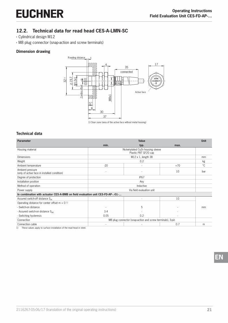
12.2. Technical data for read head CES-A-LMN-SC Ì Cylindrical design M12 Ì M8 plug connector (snap-action and screw terminals)
Dimension drawing
17
5
32 19,7
R eading distance s
Cen
tre o
ffset
m
connected
354
830
M12
x1
M8x
1
37
1)
1)
Active face
1) Clear zone (area of the active face without metal housing)
Technical data
Parameter Value Unit
min. typ. max.Housing material Nickel-plated CuZn housing sleeve
Plastic PBT GF20 cap
Dimensions M12 x 1, length 38 mm
Weight 0.2 kg
Ambient temperature -20 - +70 °C
Ambient pressure (only of active face in installed condition) - - 10 bar
Degree of protection IP67
Installation position Any
Method of operation Inductive
Power supply Via field evaluation unit
In combination with actuator CES-A-BMB on field evaluation unit CES-FD-AP-.-01-…Assured switch-off distance Sar - - 10
mm
Operating distance for center offset m = 0 1)
- Switch-on distance - 5 -
- Assured switch-on distance Sao 3.4 - -
- Switching hysteresis 0.05 0.2 -
Connection M8 plug connector (snap-action and screw terminals), 3-pin
Connection cable - - 0.7 m1) These values apply to surface installation of the read head in steel.

Operating InstructionsField Evaluation Unit CES-FD-AP-…
22 (translation of the original operating instructions) 2116267-05-06/17
Typical operating distance
(only in combination with field evaluation unit CES-FD-AP-.-01-… and actuator CES-A-BMB)
Figure 5: Typical operating distance
NOTICE
Ì A minimum distance of s = 1.2 mm must be maintained. Ì The read distance may vary depending on the installation situation
2
4
6
6
8
8
X8
64
22
46
8
86
Y
Z
232116267-05-06/17 (translation of the original operating instructions)
Operating InstructionsField Evaluation Unit CES-FD-AP-…
EN
12.3. Actuator CES-A-BMB Ì Cylindrical design M12 x 75 Ì In combination with read head CES-A-LMN-SC (operating distance on request for read head CES-A-LNA…/LCA…)
Dimension drawing
11
0,80
6
M12
x0,7
5
Active face
NOTICE
Ì The actuator can be screwed into the M12 x 0.75 thread provided with the aid of an insertion tool (order no. 037 662). Ì Flush installation of the actuator in steel is permissible.
Technical data
ParameterValue
Unitmin. typ. max.
Housing material Stainless steel
Dimensions M12 x 0.75, depth 6 mm
Weight 0.002 kg
Ambient temperature -25 - +70 °C
Degree of protection IP67
Installation position Active face opposite read head
Power supply Inductive via read head

Operating InstructionsField Evaluation Unit CES-FD-AP-…
24 (translation of the original operating instructions) 2116267-05-06/17
12.4. Key adapter CKS Ì Integrated CES read head Ì M8 plug connector
Dimension drawing
40
83 75
8
LED
1,5M4
67
50 10
70,576
max. 4 mm
32
84
FR
CKS
113461
40
∅ 25,4∅ 31
5
Key adapter Key
(rubber seal) Screw clamp element
Plug connector M8
Cable outlet, angled plug connector
Active face (front and back sides)
Important!
Ì Key adapter CKS must not be used as a lockout mechanism in combination with multicode evalua-tion. Ì The key is not included with the key adapter and must be ordered separately.
Technical data
Parameter Value Unit
min. typ. max.Key adapterHousing material Plastic (PA 6 GF30)
Weight 0.13 kg
Ambient temperature -20 - +70 °C
Degree of protection IP67(in installed state)
Installation position On the front panel
Mounting cut-out according to DIN 43700 33 x 68 mm
Operating distance 1)
mmAssured switch-off distance sar - - 35
Assured switch-on distance sao 2 - -
Switching hysteresis - 1 -
Connection to field evaluation unit Plug connector M8(male socket, 3-pin)
Cable length - - 0.7 m
LED indicator White: valid key detected
KeyHousing material Plastic (PC)
Weight 0.004 kg
Ambient temperature -20 - +70 °C
Degree of protection acc. to IEC 60529 IP 67
Power supply Inductive via read head1) Referred to the stop of the inserted key.
252116267-05-06/17 (translation of the original operating instructions)
Operating InstructionsField Evaluation Unit CES-FD-AP-…
EN
13. Ordering information and accessoriesTip!
Suitable accessories, e.g. cables or assembly material, can be found at www.euchner.de. To order, enter the order number of your item in the search box and open the item view. Accessories that can be combined with the item are listed under “Accessories”.
14. Inspection and serviceWARNING
Loss of the safety function because of damage to the system.In case of damage, the related safety component must be replaced. The replacement of individual parts in a safety component is not permitted.
Regular inspection of the following is necessary to ensure trouble-free long-term operation: Ì Check the switching function (see chapter 9.4. Functional check on page 15) Ì Check the secure fastening of the devices and the connections Ì Check for soiling Ì Check for sealing of the plug connector on the safety switch Ì Check for loose cable connections on the plug connector Ì Check the switch-off distance
No servicing is required; repairs to the device are only allowed to be made by the manufacturer.
NOTICE
The year of manufacture can be seen in the lower right corner of the rating plate.
15. ServiceIf service support is required, please contact:
EUCHNER GmbH + Co. KG
Kohlhammerstraße 16
D-70771 Leinfelden-Echterdingen
Service telephone:
+49 711 7597-500
E-mail:
Internet:
www.euchner.de

Operating InstructionsField Evaluation Unit CES-FD-AP-…
26 (translation of the original operating instructions) 2116267-05-06/17
16. Declaration of conformity

272116267-05-06/17 (translation of the original operating instructions)
Operating InstructionsField Evaluation Unit CES-FD-AP-…
EN

Euchner GmbH + Co. KGKohlhammerstraße 16D-70771 [email protected]
Edition:2116267-05-06/17Title: Operating Instructions Field Evaluation Unit CES-FD-AP-… (Unicode/Multicode) (translation of the original operating instructions)Copyright:© EUCHNER GmbH + Co. KG, 06/2017
Subject to technical modifications; no responsibility is accept-ed for the accuracy of this information.