field guide to assessing pei soils for on-site sewage ... · classification perspective for use in...
TRANSCRIPT
Field Guide to Assessing PEI Soilsfor On-Site Sewage Disposal Systems
1st Edition
Prepared by:
B. C. O’Neill, M.Sc.Soil Scientist
Technical Review Committee:
Morley Foy, P.Eng.Delbert Reeves, C.E.T.
Jim Young, P.Eng.
PEI Department of Fisheries,Aquaculture and Environment
Water Resources Division
February 2002

The proper soils assessment for sewage disposal systems is an essential component in the protection of our waterresources in Prince Edward Island. Sewage disposalsystems that are installed in unsuitable soils canmalfunction and result in groundwater contamination.
This Soils Assessment Handbook, the first of its kind inPrince Edward Island, is a valuable resource to evaluatesoil suitability for on-site sewage disposal systems.
The publication of this field guide is part of the DrinkingWater Strategy to maintain the quality of PEI’s drinkingwater now and for the future.
While the Department of Fisheries, Aquaculture andEnvironment, Water Resources Division, is responsible formanaging, protecting and enhancing the Province's waterresources, many other individuals and groups play animportant role in protecting our groundwater. The SoilsAssessment Handbook is an excellent example of how theDepartment works in partnership with these groups.
J. Chester Gillan, MinisterFisheries, Aquacultureand Environment
Message from the Minister
PEI Soils Assessment Handbook
Preface
This field guide has been prepared to assist Environmental Officers, Planning Development Officers,engineering consultants and private contractors (herein referred to as “inspectors”) to describe soils in thefield. Many published references exist for describing soils; however, these references focus on evaluatingsoils for either soil genesis and classification purposes or for assessing soils for agricultural use. Thespecific intent here is to provide soils information that meets the needs of field personnel who performsite suitability analyses for on-site sewage disposal systems, using information that is relevant andapplicable to PEI soil conditions and referenced to existing PEI regulatory requirements for on-sitesewage disposal system installations.
The following sources of information are acknowledged for the information contained herein:
1. Agriculture Canada Research Branch. 1988. Soils of Prince Edward Island. PEI Soil Survey. J.I.MacDougall, C. Veer and F. Wilson (ed.) Land Resource Research Centre Publication # 83-54,Charlottetown, PE.
2. Agriculture Canada Research Branch. 1987. The Canadian System of Soil Classification. 2nd Edition. Agriculture Canada Publication #1646. Agriculture Canada Expert Committee on Soil Survey.
3. Expert Committee on Soil Survey. 1982. The Canada Soil Information System (CanSIS) Manual forDescribing Soils in the Field. J.H. Day (ed.) Land Resource Research Institute, Agriculture Canada,Ottawa.
4. Munsell® Soil Colour Charts. 1994. Munsell® Color, MacBeth Division of Kollmorgan InstrumentsCorporation, New Windsor, NY.
5. Ontario Centre for Soil Resource Evaluation. 1993. Field Manual for Describing Soils in Ontario. GuelphAgricultural Centre Publication #93-1, Guelph, ON.
6. Kelly Galloway, Engineering Technologies Canada.
i

PEI Soils Assessment Handbook
Table of Contents
Page
1 Introduction . . . . . . . . . . . . . . . . . . . . . . . . . . . . . . . . . . . . . . . . . . . . . . . . . . . . . . . . . . . . . . . . . 11.1 Definition of Soil . . . . . . . . . . . . . . . . . . . . . . . . . . . . . . . . . . . . . . . . . . . . . . . . . . . . . . . 1
2 Site Information . . . . . . . . . . . . . . . . . . . . . . . . . . . . . . . . . . . . . . . . . . . . . . . . . . . . . . . . . . . . . 22.1 General Site Information . . . . . . . . . . . . . . . . . . . . . . . . . . . . . . . . . . . . . . . . . . . . . . . . . 22.2 Surface Drainage . . . . . . . . . . . . . . . . . . . . . . . . . . . . . . . . . . . . . . . . . . . . . . . . . . . . . . . 32.3 Slope Class . . . . . . . . . . . . . . . . . . . . . . . . . . . . . . . . . . . . . . . . . . . . . . . . . . . . . . . . . . . . 32.4 Slope Position Classification . . . . . . . . . . . . . . . . . . . . . . . . . . . . . . . . . . . . . . . . . . . . . . 4
3 Description of Mineral Soils . . . . . . . . . . . . . . . . . . . . . . . . . . . . . . . . . . . . . . . . . . . . . . . . . . . . 53.1 Site Investigation Checklist . . . . . . . . . . . . . . . . . . . . . . . . . . . . . . . . . . . . . . . . . . . . . . . 53.2 Collection of Soils Information . . . . . . . . . . . . . . . . . . . . . . . . . . . . . . . . . . . . . . . . . . . 6
Form A - General Site Information . . . . . . . . . . . . . . . . . . . . . . . . . . . . . . . . . . . . . . . . . . . . . . . . . . . . . . 8
Form B - Soil Profile Description . . . . . . . . . . . . . . . . . . . . . . . . . . . . . . . . . . . . . . . . . . . . . . . . . . . . . . . 9
ii
PEI Soils Assessment Handbook
1
1 Introduction
The structure, format and much of the content of this field manual are based on information contained inthe “Field Manual for Describing Soils in Ontario - 4th Edition (1993)”, published by the Ontario Centrefor Soil Resource Evaluation (OCSRE). The OCSRE field manual is a useful tool for describing fieldsoils; however, it was designed to aid field personnel in describing soils from a soil genesis andclassification perspective for use in soils mapping and for agricultural purposes. In addition, theinformation is most applicable to soil conditions found in Ontario.
This field guide has been developed to provide soil information to field personnel, specifically for thepurposes of describing and evaluating soils for their suitability to support on-site sewage disposalsystems, using referenced soils information that is relevant to PEI. Little emphasis is placed on organicsoils in this guide since their use for sewage disposal systems is severely limited by drainage problems.
The information provided in this guide focuses on the methods for describing mineral soils that cansupport sewage disposal systems, and on describing soil properties that influence the movement of waterthrough soil, and hence, the treatment of the waste from the sewage disposal system.
1.1 Definition of Soil
The following definition of a soil is taken from the Canadian System of Soil Classification (AgricultureCanada, 1987):
“Soil is a naturally occurring, unconsolidated, mineral or organic material at the earth’s surfacethat is capable of supporting plant growth. Its properties usually vary with depth and aredetermined by climatic factors and organisms, as conditioned by relief and hence water regime,acting on geologic materials and producing genetic horizons that differ from the parent material.”
With respect to on-site sewage disposal systems, only mineral soils should be considered as potential sitessince organic soils (such as those found in depressional areas, lower slope positions and in bogs) areunsuitable for supporting the systems due to poor drainage characteristics.
Traditionally, soil investigations have been performed for soil genesis and classification for mapping oragricultural purposes and these investigations are usually limited to a depth of about one metre. Whenevaluating soils for sewage disposal systems, test pits are usually prepared to a depth of 1.8 metres (6 feet) and the focus is on evaluating soil properties such as texture, structure and internal drainagecharacteristics which most directly affect the efficiency of treatment.

PEI Soils Assessment Handbook
2
2 Site Information
When performing test pit evaluations, it is important to maintain an accurate and complete record of allsite information for reference purposes. This information must be recorded in a systematic manner toallow consistent evaluations from site to site.
Two types of information should be recorded: (1) general site information and (2) test pit (soil)information.
2.1 General Site Information
At each site being evaluated, the inspector should complete a brief site survey and record any pertinentsite information that will help to properly assess the suitability of the site for on-site sewage disposal. The general site information should be recorded using FORM A (General Site Information). Thefollowing provides a description of the types of information that should be recorded:
• Site Information - Proponent’s name and contractor’s name, phone numbers, casenumber, property number, test pit number (if more than one test pit is completed), dateexcavated, the inspector’s name, and site location.
• Site Observations/Comments - Identify the geographic location of the property,including the highway, road or rural route number. If a GPS is available, record thegeographic coordinates for the location using either NTS or UTM coordinates; provide adescription of surrounding land use; provide a description of the site characteristics,including percent slope, slope position of the proposed sewage disposal system,observations of ponded water on the soil surface (indicating poor surface drainage), typeof vegetation, etc. For a further explanation of this information, see Section 2.2, 2.3 and2.4 of this manual.
• Site Sketch - Use this section to provide a sketch of the site, including the followinginformation: a north arrow; the location of all existing or proposed structures; locations ofexisting and/or proposed site access (driveways/laneways); any physical features such astelephone poles, out buildings, trees, surface water (streams, ponds, etc.) and existing orproposed well locations. Identify where the test pit(s) and proposed sewage disposalsystem will be located; measure and record all distances from the sewage disposal systemto the above site features (see Planning Act and the Environmental Protection Act -Sewage Disposal Regulations for reference). Care should be taken to evaluate theposition of existing adjacent wells and sewage disposal systems.
PEI Soils Assessment Handbook
3
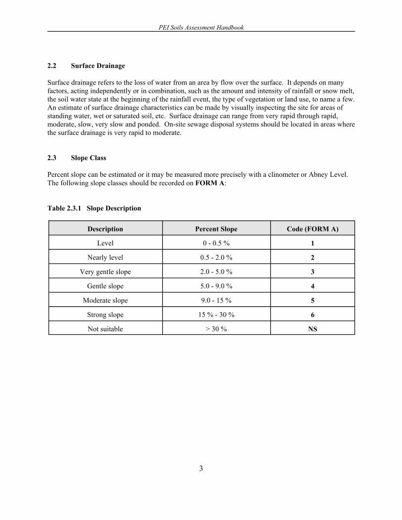
2.2 Surface Drainage
Surface drainage refers to the loss of water from an area by flow over the surface. It depends on manyfactors, acting independently or in combination, such as the amount and intensity of rainfall or snow melt,the soil water state at the beginning of the rainfall event, the type of vegetation or land use, to name a few. An estimate of surface drainage characteristics can be made by visually inspecting the site for areas ofstanding water, wet or saturated soil, etc. Surface drainage can range from very rapid through rapid,moderate, slow, very slow and ponded. On-site sewage disposal systems should be located in areas wherethe surface drainage is very rapid to moderate.
2.3 Slope Class
Percent slope can be estimated or it may be measured more precisely with a clinometer or Abney Level. The following slope classes should be recorded on FORM A:
Table 2.3.1 Slope Description
Description Percent Slope Code (FORM A)
Level 0 - 0.5 % 1
Nearly level 0.5 - 2.0 % 2
Very gentle slope 2.0 - 5.0 % 3
Gentle slope 5.0 - 9.0 % 4
Moderate slope 9.0 - 15 % 5
Strong slope 15 % - 30 % 6
Not suitable > 30 % NS

PEI Soils Assessment Handbook
4
2.4 Slope Position Classification
The design and operation of the septic system will often be determined by its actual position in thelandscape. For this reason, it is important to note where the proposed system is to be situatedtopographically. The following descriptions are included to provide a slope position designation onFORM A:
Table 2.4.1 Slope Position
Slope Position Code
Crest 1
Shoulder 2
Back Slope 3
Foot Slope 4
Depression 5
Level 6
Fig. 2.4.1 Slope Position

PEI Soils Assessment Handbook
5
3 Description of Mineral Soils
Once the general site information has been recorded, the site soils must be evaluated. Since soil propertiesmay exhibit significant spatial variability (i.e., both laterally and with depth), it is important the test pitis completed in the area where the sewage disposal field will actually be located.
3.1 Site Investigation Checklist
Step1 Obtain the soils map for the property before going to the site.
2 Contact the proponent and/or contractor to confirm your arrival time and exact locationof the property.
3 Upon arrival, review where the proposed septic field will be located with theproponent/contractor and locate the test pit.
4 Excavate the test pit to a depth of 1.2 metres (4 feet).
5 Before entering the test pit, visually inspect the soil conditions for stability. Both verydry, granular soils (such as coarse sands) or very wet, fine textured soils (i.e., thosecontaining significant silt and clay content) may become unstable and collapse during theinspection, causing injury. Do not enter a test pit that has been left unattended unlessprotective measures (i.e., shoring, etc.) have been installed to the standards established bythe Occupational Health and Safety Act.
6 After entering the test pit, prepare the soil profile for inspection by selecting arepresentative vertical column of soil. Use a knife, spatula or mason hammer to scarifythe pit face for the full depth of the test pit. This removes any smearing caused by theexcavation equipment and allows you to see the soil horizon boundaries and theirphysical characteristics more clearly.
7 Exit the test pit and have the contractor excavate an additional 0.6 metres (2 feet) so thatthe test pit is a total of at least 1.85 metres (6 feet) in depth. Without re-entering the testpit, inspect the pit for evidence of a visible water table and the presence of bedrock.
8 Have the contractor fill in the test pit. Do not leave test pits open and unattended.

PEI Soils Assessment Handbook
6
3.2 Collection of Soils Information (FORM B)
Using FORM B - Soil Profile Description, record the following information:
1 Record the depth of the root mat (surficial vegetation and organic matter) from thesurface to the start of the first mineral soil horizon. For example, record the layer as “5-0 cm.” The top layer of the mineral soil will then be the starting point for yourevaluation.
2 Starting at the top of the first mineral soil layer (i.e., below the root mat), identify thetotal depth of any visible roots, rootlets and worm holes that are present. Deeppenetration of roots and worm holes is used as an indicator of secondary permeability andindicates a well-drained soil.
3 Identify and mark distinct horizon boundaries and, using a measuring tape, record thethickness (depth) of each horizon.
4 Refer to Fig. 3.2.1 and identify the three major diagnostic horizons (A, B and C).
5 Refer to Table 3.2.1 to identify any sub-layers within these horizons. Each horizon mayhave one or more sub-units which can be identified as A1, A2, B1, B2, etc.
6 For each layer identified, record the following: texture (Fig. 3.2.2), structure (Table3.2.2), Munsell colour (Fig. 3.2.6), density (Table 3.2.3), and drainage classification(Table 3.2.4).
7 Site Observations: look for evidence of dense or confining layers that may impededrainage, and record depth if present. This may be assessed using the re-bar techniquesdescribed in Table 3.2.3.
8 Complete FORM B and using the data recorded in Steps 1 to 7, categorize the soils asper the Planning Act regulations.

PEI Soils Assessment Handbook
7
Major Soil Horizon Designations
Table 3.2.1 Visual Description of Typical Mineral Soil Horizons in PEI
Horizon Designation Description
A1 Darker coloured surface layer enriched with organic matter.
A2 Lighter coloured A horizon; light colour due to loss of iron, organic matter, or clay.
AB A transitional layer sometimes present (difficult to distinguish clear boundary betweenA and B).
B1 Reddish-brown sub-surface layer that may be enriched with iron, clay, etc. Observabledifference from A due to change in colour, texture, structure or density.
B2 Presence of another B layer that is different from B1 due to a change in one or more ofthe following: texture, structure, colour, or density.
BC A transition between B and C. Boundary difficult to distinguish.
C Unweathered, parent material.
Please Note: 1 This table provides a generalized list of typical horizons. Individual sites may differ wheresome sites may not contain any sub-units (i.e., A2, AB, B2, BC may not be present) whileat other sites additional layers may be present (i.e., A3, B3, etc.).
2 Actual colour must be identified using the Munsell Soil Colour Chart.
Fig. 3.2.1 Major Soil Horizon Designation

PEI Soils Assessment Handbook
8
FORM A - General Site Information
Proponent’s Name: Phone No.:
Contractor: Phone No.:
Case No.: Property No.:
Test Pit No.: Date Excavated:
Inspector (Print): Inspector (Signature)
Site Location: Geographic Coordinates.:
Site Observations/Comments:
% Slope (Section 2.3):
Slope Position of Proposed Septic System(Section 2.4):
Site Sketch

PEI Soils Assessment Handbook
9
FORM B - Soil Profile Description
Proponent: Case No.: Property No.: Inspector: Date: Time: Root Mat Depth: Rooting Zone Depth: Test Pit No.: Weather Conditions:
HorizonFig. 3.2.1
Table 3.2.1Depth (cm)
Texture(Fig. 3.2.2)
Structure(Table 3.2.2)
Colour(Fig. 3.2.6)
Density(Table 3.2.3)
Drainage Class (cm)
0 - 60 60 - 120 120 - 180
Estimated Depth of Permeable Soil: cm Depth to Confining Layer (if applicable): cm Depth of Test Pit: cm
Depth to Water Table: < 60 cm 9 60 to 120 cm 9 120 to 180 9Depth to Bedrock: < 60 cm 9 60 to 120 cm 9 120 to 180 9Comments:
Lot Category: Inspector’s Signature:
Recommendations:

PEI Soils Assessment Handbook
10
Finger Assessment of Soil Texture
Fig. 3.2.2 - Soil Texture
For a description of each test method, see next page.
PEI Soils Assessment Handbook
11
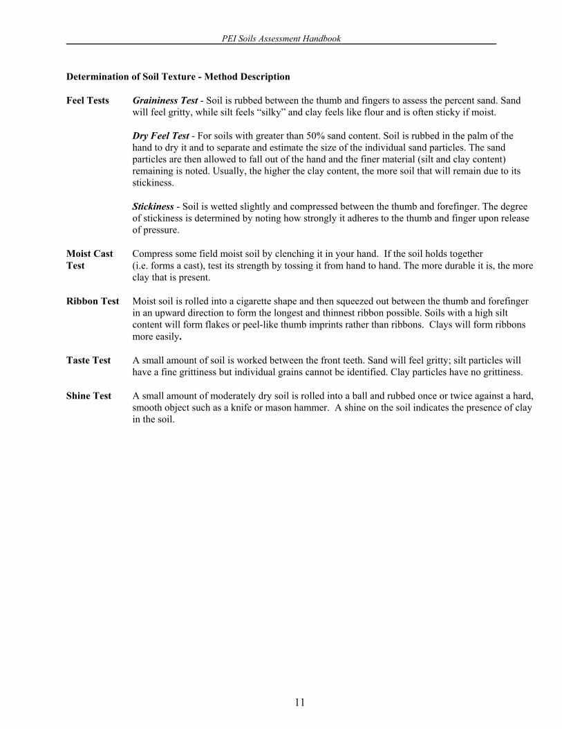
Determination of Soil Texture - Method Description
Feel Tests Graininess Test - Soil is rubbed between the thumb and fingers to assess the percent sand. Sandwill feel gritty, while silt feels “silky” and clay feels like flour and is often sticky if moist.
Dry Feel Test - For soils with greater than 50% sand content. Soil is rubbed in the palm of thehand to dry it and to separate and estimate the size of the individual sand particles. The sandparticles are then allowed to fall out of the hand and the finer material (silt and clay content)remaining is noted. Usually, the higher the clay content, the more soil that will remain due to itsstickiness.
Stickiness - Soil is wetted slightly and compressed between the thumb and forefinger. The degreeof stickiness is determined by noting how strongly it adheres to the thumb and finger upon releaseof pressure.
Moist Cast Compress some field moist soil by clenching it in your hand. If the soil holds togetherTest (i.e. forms a cast), test its strength by tossing it from hand to hand. The more durable it is, the more
clay that is present.
Ribbon Test Moist soil is rolled into a cigarette shape and then squeezed out between the thumb and forefingerin an upward direction to form the longest and thinnest ribbon possible. Soils with a high siltcontent will form flakes or peel-like thumb imprints rather than ribbons. Clays will form ribbonsmore easily.
Taste Test A small amount of soil is worked between the front teeth. Sand will feel gritty; silt particles willhave a fine grittiness but individual grains cannot be identified. Clay particles have no grittiness.
Shine Test A small amount of moderately dry soil is rolled into a ball and rubbed once or twice against a hard,smooth object such as a knife or mason hammer. A shine on the soil indicates the presence of clayin the soil.
PEI Soils Assessment Handbook
12
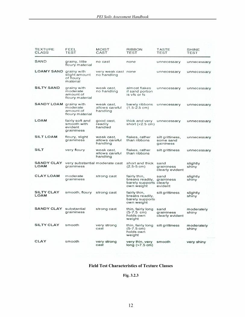
Field Test Characteristics of Texture Classes
Fig. 3.2.3

PEI Soils Assessment Handbook
13
Fig. 3.2.4
PEI Soils Assessment Handbook
14
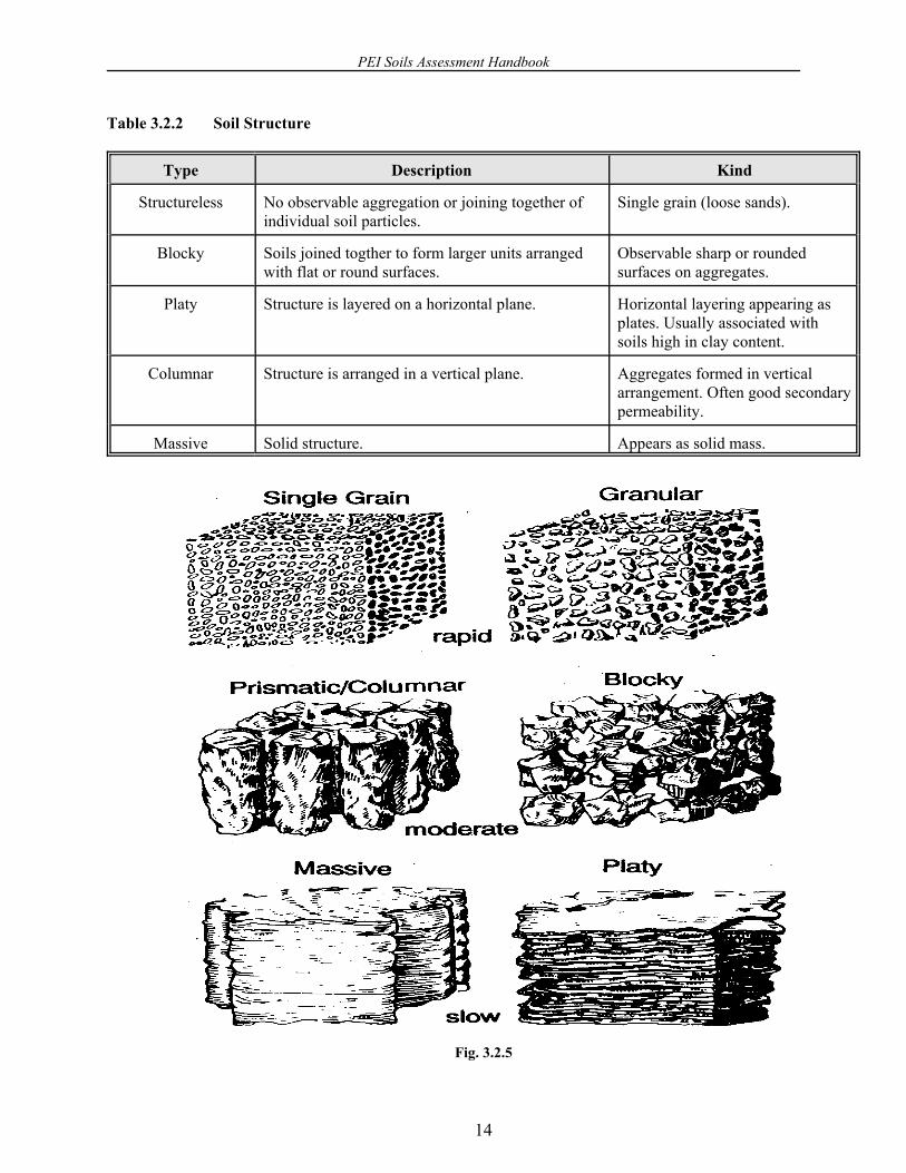
Table 3.2.2 Soil Structure
Type Description Kind
Structureless No observable aggregation or joining together ofindividual soil particles.
Single grain (loose sands).
Blocky Soils joined togther to form larger units arrangedwith flat or round surfaces.
Observable sharp or roundedsurfaces on aggregates.
Platy Structure is layered on a horizontal plane. Horizontal layering appearing asplates. Usually associated withsoils high in clay content.
Columnar Structure is arranged in a vertical plane. Aggregates formed in verticalarrangement. Often good secondarypermeability.
Massive Solid structure. Appears as solid mass.
Fig. 3.2.5

PEI Soils Assessment Handbook
15
Soil Colour and Moisture Condition
Soil colour is an indication of soil development processes which have taken place, soil drainage and water tablefluctuations. Using the Munsell Soil Colour Charts, separate descriptions of HUE, VALUE and CHROMA arerecorded (in that order) to form a Munsell notation.
The HUE represents a page in the Munsell Colour Chart and is the letter abbreviation R for red, YR for YellowRed, and Y for yellow, and is preceded by a number from 1 to 10. As the number increases within each letterrange, the HUE becomes more yellow and less red.
The VALUE represents the relative lightness of a colour, while the CHROMA represents the relative purity,strength or saturation of a colour.
Use the Munsell Colour Chart as follows:
1 Select the appropriate HUE card.2 Hold the soil sample directly behind the card apertures separating the closest matching colour
chips.3 Record the soil colour using the notation: HUE VALUE/CHROMA. For example, a typical
Charlottetown soil may have a horizon that is a 2.5YR 4/6m. The suffix “m” indicates the colourof the soil when “moist”, whereas the same soil dry (d) might be a 5YR 5/6d.
Fig. 3.2.6 Munsell Soil Colour Chart
PEI Soils Assessment Handbook
16
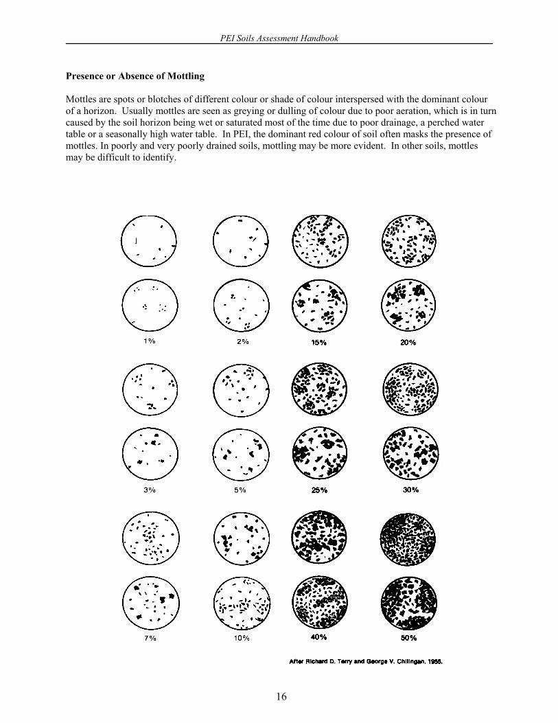
Presence or Absence of Mottling
Mottles are spots or blotches of different colour or shade of colour interspersed with the dominant colourof a horizon. Usually mottles are seen as greying or dulling of colour due to poor aeration, which is in turncaused by the soil horizon being wet or saturated most of the time due to poor drainage, a perched watertable or a seasonally high water table. In PEI, the dominant red colour of soil often masks the presence ofmottles. In poorly and very poorly drained soils, mottling may be more evident. In other soils, mottlesmay be difficult to identify.

PEI Soils Assessment Handbook
17
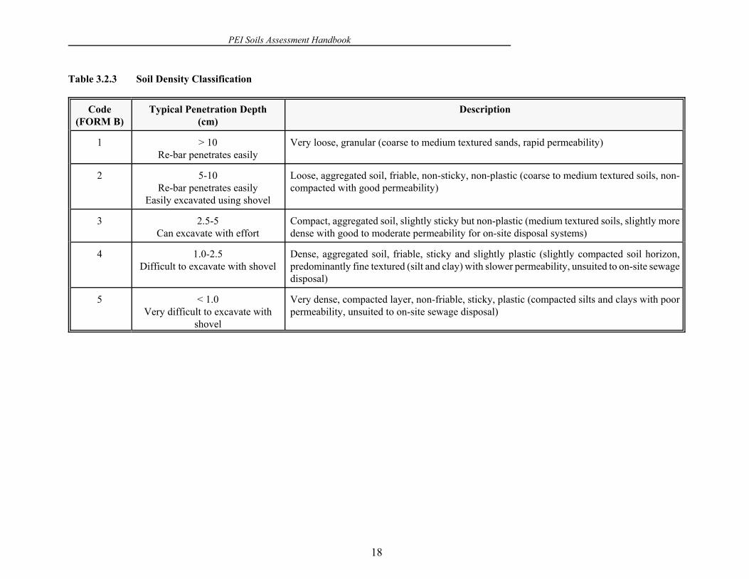
Soil Density
Soil structure is defined as the arrangement of primary soil particles (sand, silt and clay) into secondaryparticles (aggregates). Aggregated soils are considered to be better suited for on-site sewage disposalsystems because they generally have lower bulk densities, good porosity and thus exhibit permeabilitiesthat are neither “too fast” nor “too slow” to allow for proper treatment of the sewage to occur. Forexample, coarse sands may allow water to move through the soil profile at too high a rate, whereas finetextured soils such as clays will restrict movement. The measurement of soil bulk density is often used asa relative measure of soil structure and permeability. Precise determination of bulk density is not requiredbut may be accomplished by collecting soil cores and determining bulk density in the laboratory. For thepurposes of assessing the site for suitability for on-site sewage disposal, the inspector can estimate soildensity by two methods: resistence to penetration using a soil probe (i.e. a re-bar), and evaluating theconsistency of soil aggregates by hand.
Step 1
Prepare a soil probe made from a minimum 1.25 cm diameter (0.5 inch) re-bar. Use the re-bar to probeeach horizon independently to assess the density of the soil. Make sure that an equal amount of pressure isapplied each time. Observe the penetration depth of the re-bar for all horizons from 0-120 cm (0-4 feet)and for 120-180 cm (4-6 feet) depths and record in FORM B. Note the depths of any confining layers inthe comments section of FORM B.
Step 2
Assess the nature and consistency of the soil aggregates by collecting an aggregate from each horizon.Soils that are permeable will range from a loose, granular texture to aggregates that are easily broken up inyour hand (i.e. friable). Soils with increasing silt and clay content will become less friable and may besticky to the touch. In addition, if the clay content is significant, the aggregate may be plastic or slightlyplastic (i.e. the aggregate will not break easily and can be molded in the hand like putty). These soils willhave a lower permeability and are less suited for on-site sewage disposal systems.
PEI Soils Assessment Handbook
18
Table 3.2.3 Soil Density Classification
Code(FORM B)
Typical Penetration Depth(cm)
Description
1 > 10Re-bar penetrates easily
Very loose, granular (coarse to medium textured sands, rapid permeability)
2 5-10Re-bar penetrates easily
Easily excavated using shovel
Loose, aggregated soil, friable, non-sticky, non-plastic (coarse to medium textured soils, non-compacted with good permeability)
3 2.5-5Can excavate with effort
Compact, aggregated soil, slightly sticky but non-plastic (medium textured soils, slightly moredense with good to moderate permeability for on-site disposal systems)
4 1.0-2.5Difficult to excavate with shovel
Dense, aggregated soil, friable, sticky and slightly plastic (slightly compacted soil horizon,predominantly fine textured (silt and clay) with slower permeability, unsuited to on-site sewagedisposal)
5 < 1.0Very difficult to excavate with
shovel
Very dense, compacted layer, non-friable, sticky, plastic (compacted silts and clays with poorpermeability, unsuited to on-site sewage disposal)
PEI Soils Assessment Handbook
19
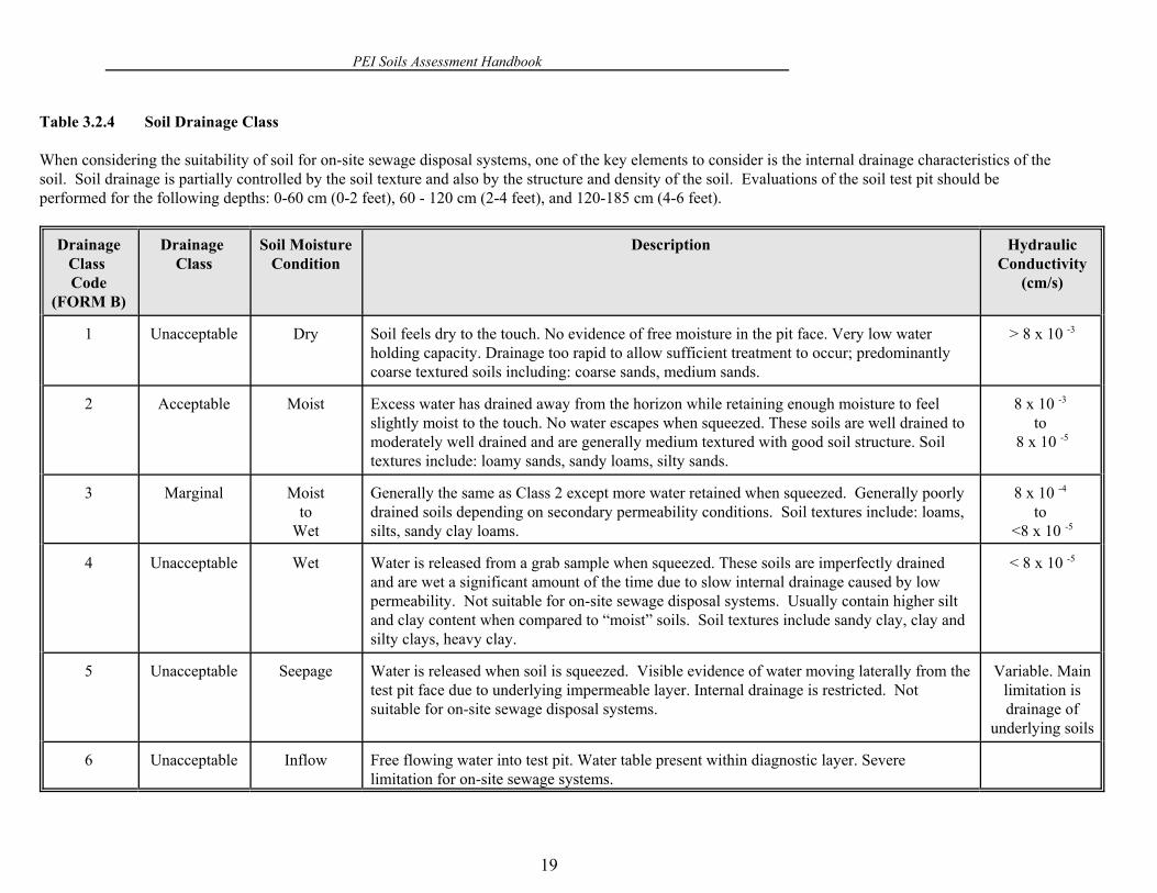
Table 3.2.4 Soil Drainage Class
When considering the suitability of soil for on-site sewage disposal systems, one of the key elements to consider is the internal drainage characteristics of thesoil. Soil drainage is partially controlled by the soil texture and also by the structure and density of the soil. Evaluations of the soil test pit should beperformed for the following depths: 0-60 cm (0-2 feet), 60 - 120 cm (2-4 feet), and 120-185 cm (4-6 feet).
DrainageClass Code
(FORM B)
Drainage Class
Soil MoistureCondition
Description HydraulicConductivity
(cm/s)
1 Unacceptable Dry Soil feels dry to the touch. No evidence of free moisture in the pit face. Very low waterholding capacity. Drainage too rapid to allow sufficient treatment to occur; predominantlycoarse textured soils including: coarse sands, medium sands.
> 8 x 10 -3
2 Acceptable Moist Excess water has drained away from the horizon while retaining enough moisture to feelslightly moist to the touch. No water escapes when squeezed. These soils are well drained tomoderately well drained and are generally medium textured with good soil structure. Soiltextures include: loamy sands, sandy loams, silty sands.
8 x 10 -3 to
8 x 10 -5
3 Marginal Moistto
Wet
Generally the same as Class 2 except more water retained when squeezed. Generally poorlydrained soils depending on secondary permeability conditions. Soil textures include: loams,silts, sandy clay loams.
8 x 10 -4 to
<8 x 10 -5
4 Unacceptable Wet Water is released from a grab sample when squeezed. These soils are imperfectly drainedand are wet a significant amount of the time due to slow internal drainage caused by lowpermeability. Not suitable for on-site sewage disposal systems. Usually contain higher siltand clay content when compared to “moist” soils. Soil textures include sandy clay, clay andsilty clays, heavy clay.
< 8 x 10 -5
5 Unacceptable Seepage Water is released when soil is squeezed. Visible evidence of water moving laterally from thetest pit face due to underlying impermeable layer. Internal drainage is restricted. Notsuitable for on-site sewage disposal systems.
Variable. Mainlimitation isdrainage of
underlying soils
6 Unacceptable Inflow Free flowing water into test pit. Water table present within diagnostic layer. Severelimitation for on-site sewage systems.