field oriented control of dfig in wind energy …textroad.com/pdf/jbasr/j. basic. appl. sci. res.,...
TRANSCRIPT

J. Basic. Appl. Sci. Res., 2(11)11486-11493, 2012
© 2012, TextRoad Publication
ISSN 2090-4304 Journal of Basic and Applied
Scientific Research www.textroad.com
*Corresponding Author: M.R.Esmaeeli, Department of Electrical Engineering, Shahid Chamran University, Ahvaz, Iran, phone: +989179927852, Email: [email protected].
Field Oriented Control of DFIG in Wind Energy Conversion Systems
M.R. Esmaeeli, R. Kianinezhad, M. Razzaz
Department of Electrical Engineering, Shahid Chamran University, Ahvaz, Iran
ABSTRACT
Doubly-fed induction generator (DFIG) is one of the best choices in wind turbine generator. Nowadays control of DFIG is done in different strategy and this paper discusses the decoupled FOC control with MRAS observer for wind turbine generator and compares with open loop estimator strategy. The proposed sensorless algorithm obtained required information by measuring stator voltage, stator and rotor currents. This strategy is applicable in whole wind speed range and simulation results in MATLAB/SIMULINK verify the effect of this method on DFIG control. KEYWORDS: Doubly-fed induction generator, RSC, GSC, MRAS observer.
INTRODUCTION For a long years coal and oil was a main source of energy. This type of energy is pollutant and has
undesirable effects on environment. Fossil fuels produce carbon dioxide that contributes in warm climate, acid rains and environmental problems. In addition, coal and oil are going to the end point, therefore, interest in use of renewable energy has extended. Among the renewable energy, wind energy is playing the important role because have a lower pollution and is in access all over the world. Since the end of 20th century and at the beginning of 21th the numbers of wind farm grow as today this energy have a role that is impossible to ignore. In fixed speed wind energy conversion system often uses from squirrel-cage induction generator that is connected to grid directly. This machine has maximum efficiency at certain speeds. In variable speed generating systems, at the beginning, squirrel cage induction generator was used with back to back converter. This converter controls total power passes through the generator and it raises the cost. Today’s, doubly- fed induction generator (DFIG) is most suitable for variable-speed constant frequency generating. DFIG is connected to a utility system with stator so it must be have a fixed output voltage and frequency. Rotor is connected to a grid with back to back converter and fed through AC/DC/AC converter. .In modern DFIG design, the frequency converter is built by two PWM converters, rotor side converter, grid side converter with an intermediate DC voltage link. By controlling the converters in both sides, DFIG can captures maximum energy from the wind with high efficiency. These converters transform almost 30% of output total power and reduce cost of system because they apply their control on lower range of power[8],[10]. Back to back converter gives capability to DFIG operates in sub- synchronous and super-synchronous modes. These two modes are limited in 1/3 up and down of synchronous speed. The traditional method control of DFIG is accomplished in stator field orientation and needs to calculate stator flux reference and rotor position [2]. In general, Rotor position detection estimated with speed sensors but sensors have drawbacks and failures, especially in stormy weather where DFIG used. Sensors increase cost, reduce reliability and affected by environment. So sensorless algorithms improved and a lot of research has been done in sensorless control field [1].
Some sensorless control algorithms are: Open Loop Control, Closed Loop Control, Kalman Filter and MRAS Observer. Since in open loop strategy, rotor position is calculated from mathematical model of DFIG directly without feedback, so this strategy affected by rotor parameters. Kalman filter have a good performance to remove disturbance but its implementation is complicate. In this paper MRAS observer is proposed as a sensorless closed loop algorithm to detect speed and position of rotor. Rotor position angle served to transform parameters from rotor frame to synchronous reference frame and vice versa. Stator voltage vector linked to q and stator flux vector to d axis which called field oriented control (FOC) technique. Rotor position evaluated in MRAS observer by measuring stator voltage, stator and rotor current[4],[5]. Section 2 describes model of DFIG and discusses in decoupled P-Q control strategy in rotor side converter (RSC) and grid side converter (GSC). Section 3 present MRAS sensorless method and evaluates position and speed of rotor. Section 4 describes open loop method. The simulation results based in MATLAB/ SIMULINK environment are given in section 5 and section 6 presents the conclusion.
THE MODEL OF DFIG
Mathematical model of DFIG in rotating frame is evaluated and equations of stator and rotor voltages and flux components are written in below.
11486

Esmaeeli et al., 2012
In fact u, I, R and L are respectively stator and rotor voltage, stator and rotor current, resistance and self
inductance is magnetization inductance and is stator and rotor flux. The d-q equivalent circuit of the DFIG is given in Fig.1. In field oriented control stator flux aligned in d- axis and stator voltage fixed to q-axis.This causes that computations is simpler and linear.
Active and reactive relations are:
P and Q are directly related to and respectively and that means P and Q can be controlled by adjusting
and independently. In fact control on d-q current components leads to control on P and Q [3]. Proposed control strategy of DFIG is done by inverter back to back and PWM regulators. It is composed of two parts, rotor side converter and grid side converter. Rotor side converter controls active and reactive power inde-pendently and do this work in bidirectional power flow for super-synchronous and sub-synchronous speeds. In this converter, sum of injected voltage frequency and wind frequency must be equal to grid frequency. Grid side converter controls DC link voltage and fixed it in specific values. This is done by control on active power and reactive power is zero to give unit power factor. GSC is operating as a rectifier in this state, although in some cases GSC operates as a STATCOM and control reactive power besides DC link voltage regulation [7]. Schematic diagram of DFIG is displayed in fig.2.
Fig. 1: d-q equivalent circuit of DFIG
ROTOR SIDE CONVERTER
To implement independent control of active and reactive power, vector control scheme is the best choice. In
this method that called FOC, stator flux is oriented to d- axis and makes computation simple and fast. Since the DFIG is connected to grid it must be considered that magnitude and frequency of voltage is constant. The block diagram of proposed algorithm is shown in fig. 3. in the proposed block diagram:
11487

J. Basic. Appl. Sci. Res., 2(11)11486-11493, 2012
are compensation voltages and:
To control this converter, conversion must be done very carefully to achieve a good controller. In this scheme P and Q measured by transducers and compared with reference values. Error signals are given to the PI controller. Outputs of PI are reference d-q components of rotor current. These currents are compared with actual current and difference of them through PI controller convert to d-q voltage rotor. These components gather with compensation voltages and apply to PWM modulator.
GRID SIDE CONVERTER
The dynamic model of grid side converter is described as below:
That R and L are resistance and inductance of grid and and are d-q components of inverter. This is assumed that voltage of grid is aligned in d- axis and voltage of q- axis is zero.
It can be concluded that:
Fig.4 shows the block diagram of grid side converter. As above formula, d- axis current controls active power and q-axis current controls reactive power. In this controller the current of d -axis has two loops: first loop to control PWM modulator and second to regulate DC link voltage with PI controller. q-axis current also has two loop: one for PWM modulator and another for compensation reactive power in both sides. In this fig GSC converter operates as STATCOM and if it acts as a rectifier and power factor is unit. In rectifier state power is passed in one direction and flows from grid towards rotor through back to back converter. In above, rotor position is given by mechanical sensors, but this paper proposes a sensorless algorithm called improved MRAS observer.
MRAS OBSERVER
The main idea in introducing Model Reference Adaptive System (MRAS) is to design a closed loop controller with parameters that can be updated to change the response of the system. The output of a system is compared with desired response. Output of this comparison is error signal. Control parameters are updated based on this signal. Adaptive system should converge towards reference model till error to be zero and control parameters are in themselves ideal values. As discussed MRAS observer has two models. These two models are: model reference and adaptive system. The difference of the two models is used to create the suitable adjustment mechanism to realize the speed estimation [6]. Construction of the MRAS is shown in fig.2.
Fig.2: schematic diagram of DFIG
11488

Esmaeeli et al., 2012
Fig.3: block diagram of rotor side converter
Fig.4: block diagram of grid side converter
In this paper model reference is rotor current that measured by transducers and adaptive system is estimated
current that is given by stator voltage and current in stationary frame. In stationary frame stator flux is calculated as:
That can be concluded:
By replacing estimated speed in above:
Error signal of MRAS is obtained by cross product of actual and estimated rotor current and defined as below:
The block diagram of MRAS observer is shown in fig.6.
11489

J. Basic. Appl. Sci. Res., 2(11)11486-11493, 2012
OPEN LOOP SPEED ESTIMATOR
In this approach the DFIG is controlled in the synchronous reference frame, with the d axis aligned to stator flux vector position. Reference frame and angle relationship of DFIG are shown in fig.7. As shown, the rotor
current vectors are oriented in to the synchronous reference frame aligned with the stator flux. and is the position of the rotor current vector in the reference frame and the rotor frame, respectively. The rotor position
angle can be determined by computing and [9].
The functional relationship between the rotor currents and the stator currents as follow:
With the knowledge of stator currents, the rotor currents in the stator flux reference frame can be computed with
help of the proportionality between the stator and rotor currents. and can be directly accuired in rotor
frame by measuring three phase rotor currents and the position of stator flux can be computed from the measurement of the stator voltage.
Fig.5: construction for MRAS observer
Fig.6: proposed algorithm for MRAS observer
11490

Esmaeeli et al., 2012
Fig.7: Reference frame and angles
SIMULATION RESULTS
To simulate proposed control strategy for DFIG, MATLAB software is used. Nominal voltage and power is
380v and 1.5 MW respectively and its parameters are given in Appendix I. DC link voltage is set at 600v. According to FOC control strategy, rotor side converter controls active and reactive powers of DFIG and grid side converter consolidates DC link voltage.
Fig. 8 and 9 show stator voltage and current of DFIG. From the figure it can be concluded that waveform of stator voltage is fixed and is similar to grid voltage because stator is connected to grid whereas current of stator is variable and changes with demanded power. By rising demanded power the current goes up also and vice versa.
Fig.10 and 11 show active and reactive power. it is clear that output powers are tracking their reference very good. By comparing waveforms of power and current it can be seen that they act similar to each other. Reference active power between zero and two seconds is equal to 0.7 MW and from 2th second to 4th is -1.5 MW and then reaches to 0.5 MW. Reference reactive power first is 0.2 MVAR and rises to 1MVAR after 1.5 seconds and finally reduces to 0.5 MWAR at 3.5th second.
Fig.12 shows DC link voltage and it can be seen that voltage reaches to desired value in little time. In other words, overshoot in the fig is low and damping rate is high. This parameter is one of the best criteria for the proper operation of controller and has an important role in proposed algorithm.
This paper uses FOC strategy control and according to this, stator flux is oriented to d- axis and if it can be neglected from voltage drop on stator resistance, voltage alignes with q- axis and stator voltage on d-axis is zero. They are shown in fig.13. The amount of d-axis voltage is very low that can be considered zero.
Discussed previously that to find rotor speed and position used sensorless MRAS algorithm. This method uses voltage and current of stator and rotor to do this. Fig.14 and15 show position (rad) and speed (rad/s) of rotor. Position of rotor is varied between - and and speed is fixed to rotor shaft speed. In this paper assumed that rotor shaft speed is 300 rad/sec. from fig.15 it can be concluded that MRAS observer have a good performance and its output tracking reference by negligible error. This error has a less dependent to machine parameters.
Flux angle used in open loop estimator is shown in fig.16 and rotor position and speed in this approach are shown in fig.17 and 18. It can be conclude that MRAS responses have a less error. The open loop strategy of rotor speed is easy to understand but estimation is affected by the parameter variation in the operation process.
Fig.8: waveform of stator voltage Fig.9: waveform of stator current
11491

J. Basic. Appl. Sci. Res., 2(11)11486-11493, 2012
Fig.10: stator active power Fig.11:stator reactive power
Fig.13: DC link voltage Fig.12: q-d axis voltage stator
Fig.14: response of rotor position in MRAS Fig.15: response of rotor speed in MRAS
Fig16: response of stator flux position Fig.17: rotor position in open loop estimator
Fig.18: rotor speed in open loop estimator
11492
Esmaeeli et al., 2012
CONCLUSION
In this paper discussed vector control method that used back to back inverter to apply decoupled power control on DFIG. This algorithm designed based on stator flux orientation that makes calculations linear and gives a good performance control. Moreover, this algorithm used PWM modulator that has fast response and is robust. This control method tested in different reference power and output tracked it in different conditions. More, modified sensorless MRAS observer was introduced that offered position and speed rotor with the help of stator voltage and stator and rotor current. Simulation results confirm the ability of this scheme to control of DFIG. At the end of this paper MRAS speed estimator compares with open loop speed estimator and concluded that error in MRAS observer is less.
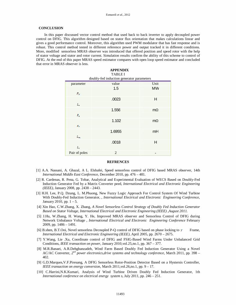
APPENDIX TABLE I
doubly-fed induction generator parameters
REFRENCES
[1] A.A. Nassani, A. Ghazal, A L. Elshafei, Speed sensorless control of DFIG based MRAS observer, 14th
International Middle East Conference, December 2010, pp. 476 – 481. [2] R. Cardenas, R. Pena, G. Tobar, Analytical and Experimental Evaluation of WECS Based on Doubly-Fed
Induction Generator Fed by a Matrix Converter peed, International Electrical and Electronic Engineering (IEEE), January 2008, pp. 2438 – 2443.
[3] H.H. Lee, P.Q. Dzung, L. M.Phuong, New Fuzzy Logic Approach For Control System Of Wind Turbine With Doubly-Fed Induction Generator, , International Electrical and Electronic Engineering Conference, January 2010, pp. 1 – 5.
[4] Xin Hao, C.W.Zhang, X. Zhang, A Novel Sensorless Control Strategy of Doubly Fed Induction Generator Based on Stator Voltage, International Electrical and Electronic Engineering (IEEE) ,August 2011.
[5] J.Hu, W.Zhang, H. Wang, Y. He, Improved MRAS observer and Sensorless Control of DFIG during Network Unbalance Voltage , International Electrical and Electronic Engineering Conference February 2009, pp. 1486 – 1491.
[6] B.shen, B.T.Ooi, Novel sensorless Decoupled P-Q control of DFIG based on phase locking to Frame, International Electrical and Electronic Engineering (IEEE), April 2005, pp. 2670 – 2675.
[7] Y.Wang, Lie .Xu, Coordinate control of DFIG and FSIG-Based Wind Farms Under Unbalanced Grid Conditions, IEEE transaction on power, January 2010,vol.25,no.1, pp. 367 – 377.
[8] M.R.Banaei, A.R.Dehghanzadeh, Wind Farm Based Doubly Fed Induction Generator Using a Novel AC/AC Converter, 2nd power electronics,drive systems and technology conference, March 2011, pp. 398 – 402.
[9] G.D.Marques,V.F.Piresang, A DFIG Sensorless Rotor-Position Detector Based on a Hystersis Controller, IEEE transaction on energy conversion, March 2011,vol.26,no.1, pp. 9 – 17.
[10] C.Harrini,N.K.Kumari, Analysis of Wind Turbine Driven Doubly Fed Induction Generator, 1th International conference on electrical energy system s, July 2011, pp. 246 – 251.
parameter value Unit
1.5 MW
.0023 H
1.556 mΩ
1.102 mΩ
1.6955 mH
.0018 H
Pair of poles 2 -
11493