figure 1: overall configuration of the robot · figure 1: overall configuration of the robot ......
TRANSCRIPT

Start-up
Figure 1: Overall Configuration of the Robot
This chapter applies to students who will be working with the robot in the lab. When you want to access therobot via the WEB, somebody must do the start-up (steps 1, 2, 3, and 4) for you and enable remote operation.When you enter the interactive control module of this tutorial you will receive a warning if the robot is notcurrently ready to operate in remote mode.
To start the robot in the lab do the following steps in order:
1. Start the computer connected to the Adept controller. It is currently configured to run Windows 98. Verifythat the RS-232 selector switch is in the correct position (channel connected to the Adept controller isselected). Double-click the PROCOMM command on the desktop. This will start a terminal emulationprogram on the PC.
2. Verify that the hose for shop air is connected to the robot and the valves at the wall and the robot base areboth turned on.
3. Turn on the power to the robot and its controller from the main switch on the front panel of the controller.After a minute or two the controller will signal its readiness with a prompt on the PC terminal. In this andall following dialogs on the terminal, you only need to type the red text:
Adept Technology, Inc. AdeptOne Robot System Boot Version 1.0
Copyright (c) 1984, 1985, 1986 by Adept Technology, Inc.
Loading from drive C...
Drive not ready, waiting...Proceeding...Done loading
ADEPT VAL-II
Copyright (c) 1984, 1985, 1986, 1987 by Adept Technology, Inc.All rights reserved.

Version: 840-767 5.1 2-121 1024K .
4. On the PC terminal type:
.enable power<CR>
.calibrate<CR>Are you sure (Y/N)? Y<CR>
These commands enable power for the servo motors and calibrate the position sensors. The robot arm willmove in response to the last command.
5. At this point you can move the robot arm from the Manual Control Pendant, teach new points or runexisting programs, or issue further commands from the PC terminal.

Movements
Figure 2: Arm Configuration
The Adept robot is a SCARA arm with four (4) degrees of freedom. That means the arm has four joints connecting
the rigid links of the arm. Starting from the base, the joints are: 1. Shoulder - connecting body and upper arm. This is a rotary joint with a range of ±150° in the horizontal plane. 2. Elbow - connecting upper and fore arms. This is a rotary joint with a range of ±147° in the horizontal plane. 3. Wrist height - connecting fore arm and wrist. This is a linear joint in the vertical axie allowing a maximum stroke
of 7.7 inch. 4. Wrist Rotation - connecting the wrist to the tool adapter. This is a twisting joint allowing ±277° of rotation.
The arm is powered with electric motors giving it a maximum pay load capacity of 2 kg (4.4 lb). The maximum reach
of the arm defines its work space. This is shown in Figure 3.
Figure 3: Maximum Workspace

Coordinate Systems 1) Joint Coordinate System
Figure 4: Joint Coordinate System (Articulated Motion) In the Joint Coordinate System a position of the robot hand in space is defined by the angles of rotation of
three joints and the linear joint of the arm. Because of the design of the arm, positions can be reached through different combinations of these angles.
Specifying a new coordinate for one of the joints results in motion of only that one joint; the endeffector (hand, tool) moves on an arc. Movement from some point A to another point B using linear interpolation in these joint coordinates does not result in straight line motion but rather follows a complex curve in three space.
This is the coordinate system used by the servo-loops of the robot controller. It allows for independent control of each joint.
2) World Coordinate System

Figure 5: Cartesian (World) Coordinate System In the world coordinate system or three space the position of the robot hand is defined by values of three
Cartesian coordinates: X, Y, and Z plus the rotation of the wrist. The directions of these axes are fixed in space. Think of its origin being firmly attached to the base of the robot arm. The location of points A and B from above can also be specified using values for x, y, and z.
Changing the values of one of these three coordinates causes the robot to move several of its joints at the same time, may be even all four of them. Movement from A to B using linear interpolation in the world coordinates results in straight line motion in three space and the orientation of the hand remains constant, i.e. its axes point in the same direction at B as it has at A and at any intermediate position.
This coordinate system makes positioning the hand from the teach pendent easier; it makes it possible for the robot to move in concert with other objects in space, for example when writing, arc welding, or paint spraying.
3) Tool Coordinate System

Figure 6: Tool Coordinate System
The tool coordinate system is attached to the tool attachment plate of the wrist and allows the robot to move easily in oblique directions in space as defined by the tool orientation.
As with the world coordinate system, changing one tool coordinate value results in movement of several robot joints. Again, the tool axes directions remain fixed while the tool position changes.
Teach Pendant
Using the Manual Control Pendant (MCP): From the manual control pendant you can control the robot arm for setup and teaching of locations. With the pendant you can move the arm in any direction, you can open and close the hand, and change its
speed. You will not be able to create programs with the pendant but you will be able to execute an existing program. In this tutorial all the buttons on the pendant will be explained:
o Move the pointer on any button, and a brief description pops up. o Click on any button and its function will be described in this window.
Keys:
Slow
Manual Mode
Common Function
Joint Axis
Speed Bar (+)
Panic Button
Function Button
Soft Buttons

Instruction Set The Val II instruction set for the Adept robot can be divided into several subsets depending on the general function an
instruction executes. In the following table only those instructions are listed which are deemed necessary for the
student to successfully understand this tutorial:
Using the Editor The Editor is used to write new V programs and to make changes to a program after it has been written. In the
following, your typed input is printed in red, while the computers prompt and responses are in black. To edit a
program, (that is, to enter the editor) type:
.EDIT program<CR>
where "program represents the name of the program you want to create or edit. Once you are in the editor, there are
several operations which you may perform on the program. They include:
* Replace an existing line in a program with a new one
* Proceed to (display) next line (<CR>)
* List the previous line (L)
* Delete one (D) or more (D n) existing line(s)
* Insert a new line between two existing lines (I); all following lines will automatically be renumbered.
* Skip to a new line (S n)
* List a group of lines (P n)
* Replace a portion of a line (R,string); if ",string" is omitted, the remainder of the line will be deleted.
* Exit the editor (E)
* Change to a new Program (C); exit the current program and open a new one.
Look at the following exercise:
.EDIT example<CR> Invoke the editor on a new program "example";
1 .Program example()
1?<CR> this causes the V system to open the editor and display the first line which is created automatically.
2?SPEED 50 ALWAYS<CR> enter next program line terminated by the <ENTER> key
3?L<CR> editor displays next line number - type L to list previous line
2 SPEED 50 ALWAYS
2? R,40 ALWAYS<CR>

2? SPEED 40 ALWAYS<CR> to replace the 40 by a 50 on this line, space the cursor under the character to be
replaced, then type R, followed by the new characters terminated by <CR>
3?APPROS A,100<CR>
4?MOVES A<CR>
5?CLOSEI<CR>
6?DEPARTS 100<CR>
7?APPROS B,100<CR>
8?MOVES B<CR>
9?OPENI<CR>
10?DEPARTS 100<CR> Enter the remaining program lines as shown.
11?E<CR>
. exit the editor by typing E and <CR>; note that the system prompt "." is now displayed.
Monitor Commands A monitor command is a system command used at the programmer's terminal for manipulation of programs and data,
control of program execution, and general control of system status.
Table 1 provides a list of special characters involving the use of the control <CTRL> key on the keyboard pressed
simultaneously with another key.
Table 1: Special Characters Character Definition
<CTRL C> Abort the program (procedure) in progress
<CTRL O> Stops output to the terminal. Pressing <CTRL O> again resumes the terminal output; does
not affect program execution.
<CTRL Q> Restarts scrolling of the display after halted by <CTRL S>.
<CTRL R> Redraw an input line.
<CTRL S> Stop scrolling of the display.
<CTRL U> Delete an entire line entry.

<CTRL W> Slows down scrolling but does not stop it. Resume normal speed by pressing <CTRL W>
again.
<CTRL Z> Abort a program when it is prompting for input.
The system is equipped with three mass storage devices used for storing programs, locations, or other data: Floppy
drives A: and B: and hard disk C: which is the default device.
-- Warning -- When system power is turned off, any programs or data not stored on a mass storage device will be lost!
There are five primary commands used for operating the mass storage devices. They are:
STORE Stores information on a disk
LOAD Retrieves information from a disk
FDIRECTORY Lists the directory of all files on a disk
FDELETE Deletes information from a disk
FORMAT Formats a new diskette
When operating the mass storage devices, you must specify which device you want to communicate with; unless you
are using the default which is drive C:.
There are eight monitor commands used to control program execution; they are:
SPEED X
X is the desired speed as a percentage of the normal speed for your program.
STATUS This command will cause a display on the screen of the current status of the
manipulator, including speed.
DIRECTORY will list all programs in active (RAM) memory.

LISTP lists the instructions in the named program.
LISPL lists all currently defined locations in active (RAM) memory.
EXECUTE Programs are executed from the terminal with this command followed by the program
name. When a program is running, the prompt changes to "*". When the program
completes, the display is as follows:
Program Completed
Stopped at program, step nn ABORT
You can terminate a program early by entering this command. It will cause the
following display:
Aborted
Stopped at program, step nn PROCEED
An aborted program can be continued from where it left of with this command.
IO This command is used to display the status of all binary input and output ports. The
display is continuously updated and is useful for verifying the operation of external
devices connected to the ports. To stop the display, enter <CTRL C>, this will abort
the IO command.
WHERE causes the robot to display the current location in the form:
world coordinates (X, Y, Z, Yaw, Pitch, and Roll) as well as the joint coordinates (1, 2,
3, and 4)
Robot Instructions The Adept V system is a computer-based control system and programming language designed specifically for
use with Adept Technology industrial robots. The V robot programming language is an integral part of
the control system. In this section several simple programming instructions will be discussed for moving the robot
arm, teaching locations, and dealing with binary I/O.
Program Variables:
When writing V programs you will need to understand how variables are used by your programs. Variables have the
following uses:

1. Robot locations 2. Real values, variables and expressions 3. String values, variables and expressions 4. System parameters and switches
The names for variables are assigned by the programmer. Each name must start with a letter and can contain only
letters, numbers, periods, and underline characters. Letters used in variable names can be entered in either
uppercase or lowercase. V always displays variable names in lowercase. Variable names can have up to 15
characters.
All numerical values are decimal. For each numerical argument, a mathematical expression can be used to specify
the value of the argument. The following rules determine how the value of an expression will be interpreted in various
situations:
1. Distances are used to define locations to which the robot is to move. The unit measure for distances is the millimeter. Values entered for distances can be positive or negative.
2. Angles in degrees are entered to define and modify orientations the robot hand is to assume at named locations, and to describe angular positions of a robot joint. Angle values can be positive or negative, with their magnitude limited by 180 degrees or 360 degrees depending on usage.
3. Scalar Variables can be assigned real values. Such values can range from -9.22E+18 to 9.22E+18.
4. Joint numbers are integers from one (1) up to the number of joints in the robot, including the hand if a servo controlled hand is operational. Joint numbering starts with the rotation about the base referred to as joint 1.
5. Signal numbers are used to identify binary (on/off) signals. They are always considered as integer values with magnitudes in the range from 1 to 512, 1001 to 1512, or 2001 to 2512. A negative signal number indicates an "off" state.
Transformations:
A transformation is a robot-independent representation of the position and orientation of
the robot endeffector. Robot independence is achieved by defining locations in terms of a Cartesian (x, y, z)
reference frame fixed to the base of the robot. The position of the endeffector is defined with X, Y, and Z coordinates.
Its orientation is defined by three angles measured from the coordinate axes. These angles are called yaw (y), pitch
(p), and roll (r). The Adept One robot in the robot lab only has four degrees of freedom, thus yaw and pitch are fixed
at: y = 0° and p = 180°.
One of the most powerful features of transformations is the ability to define locations as combinations of
transformations. Such definitions can be used, for example, to define the location of a part relative to its
carrier, and to define the location of the carrier relative to a conveyor belt which is located relative to the robot.
Compound transformations provide a means of specifying locations relative to the locations represented by other
transformations. This is a very useful facility in situations when several locations can be defined relative to a
reference location. Then, if the robot or reference is later moved, only the transformation specifying the reference
need be updated. Compound transformations are specified by a combination of transformation names separated by
colons. Example:

MOVE plate:object:grasp
Note that location functions which have transformation values can be used as any component of a compound
transformation, as in:
MOVES BASE:plate:object:grasp:TRANS(100, -20,0,0,0,90)
It should also be noted that the order in which relative transformations are specified is generally
crucial:
plate:object:grasp - yields the desired result;
grasp:object:plate - does not.
Transformations can also be scaled and shifted. Two functions are provided for this purpose:
SCALE(transformation BY scale_factor) - returns a transformation value equal to the transformation parameter with
its position scaled by the scale factor.
SHIFT(transformation BY dx, dy, dz) - returns a transformation value resulting from shifting the position of the
transformation parameter by the given amounts.
Moving the arm:
Please note: In the following command descriptions, location can stand for a location variable, a simple
transformation, a relative transformation, or a compound transformation and distance is a real value or variable
specifying an offset in mm.
MOVE location
MOVES location
Move the robot arm in joint interpolated motion from the current position
to locationwhere each joint is controlled individually. This results in the tool tip
describing arcs, rather than straight lines. To command a straight-line motion
rather than a joint interpolated motion, use the MOVES instruction.
APPRO location, distance
APPROS location, distance
When moving material into and out of boxes, it is necessary to move the
manipulator to a position above the box, followed by a motion straight down into
the box, or the arm would collide with the box. These two instructions are used to
approach the box relative to the taught location, but a distance above it.
DEPART distance
DEPARTS distance
To move the arm out off the box, these instructions are used. The hand is moved
a vertical distance from the current position.
OPENI Open the gripper.
CLOSEI Close the gripper.
RELAXI Limps the gripper (turns off air pressure to both open & close actuators.
BREAK Suspend program execution until the robot reaches its current destination.
BRAKE Causes the current robot motion to be aborted immediately.
Defining/Teaching locations & transforms:
HERE location
This command assigns a name to the current location of the robot arm which can later
be used in a program.
TEACH location
This instruction allows the operator to teach several locations by repositioning the arm
and pressing the REC/DONE button on the teach pendant. The positions will be
named: location, location1, location2, etc. Pressing <CR> on the keyboard terminates
the session.
TRANS(X,Y,Z,y,p,r)
This function returns a transformation value computed from the given X, Y, Z position
displacements and the y, p, r orientation rotations. Examples:
circle=trans(radius*cos(angle),radius*sin(angle), 0, 0, 0, 0)
move center:trans(100,-50,20,0,0,45)
In these examples, circle and center are location/ transformation names
and radiusand angle are real-valued variables.
SHIFT(location BY X,Y,Z)
This function returns a transformation value resulting from shifting the location by X,
Y, Z position displacements. Example:
move shift(center by 100,-50,20)
In this example, center is a location or transformation and X, Y, and Z are real-
valued variables/constants.
TOOL transform
Set the internal transformation used to represent the location and orientation of the tool
tip relative to the tool mounting flange of the robot. Example:
tool welding.gun

In this example, welding.gun is a transformation. It can be defined from
the keyboardby typing:
. point weld ing.gun<CR>
X Y Z y p r
0.0 0.0 0.0 0.0 0.0 0.0
change? ,,100<CR>
0.0 0.0 100.0 0.0 0.0 0.0
change? <CR>
.
The tool transformation is automatically applied each time the location of the robot is
requested or robot motions are commanded either manually (in WORLD or TOOL
modes) or in a program.
Binary I/O:
SIGNAL I
SIGNAL -I
This instruction turns a binary output signal ON or OFF (-).
On the Adept robot output signals numbered 17 through 32 are available.
SIG(I)
SIG(I,J)
SIG(-I)
Use this to read the binary input signals; returns TRUE if input I is on and false if it is off. The second
form provides a logical AND of signals I and J. A minus sign can be used to invert a binary signal.
On the Adept robot input signals numbered 1001 through 1016 are available.
ARCON
Turns welding arc ON:
AC = <current output, A> AV = <voltage output, V> or AVP = <voltage ratio, %> T = <time, s> V = <welding
speed> ASF# (<welding start condition file number>) RETRY
examples: ARCON; ARCON ASF# (1);
ARCON AC = 230 AVP = 90 T = 1.00 V = 160 RETRY
ARCOF
Turns welding arc OFF
AC = <current output, A> AV = <voltage output, V> or AVP = <voltage ratio, %> T = <time, s> AEF#
(<welding end condition file number>) ANTSTK

examples: ARCOF; ARCOF AEF# (1);
ARCOF AC = 230 AVP = 90 T = 1.00 ANTSTK
ARCCUR
Specifies the current output for welding:
AC = <current output, A>
example: ARCCUR AC = 200
ARCVOL
Specifies the voltage output for welding:
AV = <voltage output, V> or AVP = <voltage ratio, %>
example: ARCVOL AV = 28.0; ARCVOL AVP = 100
AWELD
Outputs the current instruction value for welding:
<current instruction value> (range: -14.1 to 14.0 V)
example: AWELD 12
VWELD
Outputs the voltage instruction value for welding:
<voltage instruction value> (range: -14.1 to 14.0 V)
example: VWELD 2.5
WVON
Starts weaving operation:
WEV# (<weaving condition file number>) (range: 1 to 16)
example: WVON WEV# (12)
WVOF Stops weaving operation:
example: WVOF

Instruction Set The Val II instruction set for the Adept robot can be divided into several subsets depending on the general function an
instruction executes. In the following table only those instructions are listed which are deemed necessary for the
student to successfully understand this tutorial:
Using the Editor The Editor is used to write new V programs and to make changes to a program after it has been written. In the
following, your typed input is printed in red, while the computers prompt and responses are in black. To edit a
program, (that is, to enter the editor) type:
.EDIT program<CR>
where "program represents the name of the program you want to create or edit. Once you are in the editor, there are
several operations which you may perform on the program. They include:
* Replace an existing line in a program with a new one
* Proceed to (display) next line (<CR>)
* List the previous line (L)
* Delete one (D) or more (D n) existing line(s)
* Insert a new line between two existing lines (I); all following lines will automatically be renumbered.
* Skip to a new line (S n)
* List a group of lines (P n)
* Replace a portion of a line (R,string); if ",string" is omitted, the remainder of the line will be deleted.
* Exit the editor (E)
* Change to a new Program (C); exit the current program and open a new one.
Look at the following exercise:
.EDIT example<CR> Invoke the editor on a new program "example";
1 .Program example()
1?<CR> this causes the V system to open the editor and display the first line which is created automatically.
2?SPEED 50 ALWAYS<CR> enter next program line terminated by the <ENTER> key
3?L<CR> editor displays next line number - type L to list previous line
2 SPEED 50 ALWAYS
2? R,40 ALWAYS<CR>

2? SPEED 40 ALWAYS<CR> to replace the 40 by a 50 on this line, space the cursor under the character to be
replaced, then type R, followed by the new characters terminated by <CR>
3?APPROS A,100<CR>
4?MOVES A<CR>
5?CLOSEI<CR>
6?DEPARTS 100<CR>
7?APPROS B,100<CR>
8?MOVES B<CR>
9?OPENI<CR>
10?DEPARTS 100<CR> Enter the remaining program lines as shown.
11?E<CR>
. exit the editor by typing E and <CR>; note that the system prompt "." is now displayed.
Monitor Commands A monitor command is a system command used at the programmer's terminal for manipulation of programs and data,
control of program execution, and general control of system status.
Table 1 provides a list of special characters involving the use of the control <CTRL> key on the keyboard pressed
simultaneously with another key.
Table 1: Special Characters Character Definition
<CTRL C> Abort the program (procedure) in progress
<CTRL O> Stops output to the terminal. Pressing <CTRL O> again resumes the terminal output; does
not affect program execution.
<CTRL Q> Restarts scrolling of the display after halted by <CTRL S>.
<CTRL R> Redraw an input line.
<CTRL S> Stop scrolling of the display.
<CTRL U> Delete an entire line entry.

<CTRL W> Slows down scrolling but does not stop it. Resume normal speed by pressing <CTRL W>
again.
<CTRL Z> Abort a program when it is prompting for input.
The system is equipped with three mass storage devices used for storing programs, locations, or other data: Floppy
drives A: and B: and hard disk C: which is the default device.
-- Warning -- When system power is turned off, any programs or data not stored on a mass storage device will be lost!
There are five primary commands used for operating the mass storage devices. They are:
STORE Stores information on a disk
LOAD Retrieves information from a disk
FDIRECTORY Lists the directory of all files on a disk
FDELETE Deletes information from a disk
FORMAT Formats a new diskette
When operating the mass storage devices, you must specify which device you want to communicate with; unless you
are using the default which is drive C:.
There are eight monitor commands used to control program execution; they are:
SPEED X
X is the desired speed as a percentage of the normal speed for your program.
STATUS This command will cause a display on the screen of the current status of the
manipulator, including speed.
DIRECTORY will list all programs in active (RAM) memory.

LISTP lists the instructions in the named program.
LISPL lists all currently defined locations in active (RAM) memory.
EXECUTE Programs are executed from the terminal with this command followed by the program
name. When a program is running, the prompt changes to "*". When the program
completes, the display is as follows:
Program Completed
Stopped at program, step nn ABORT
You can terminate a program early by entering this command. It will cause the
following display:
Aborted
Stopped at program, step nn PROCEED
An aborted program can be continued from where it left of with this command.
IO This command is used to display the status of all binary input and output ports. The
display is continuously updated and is useful for verifying the operation of external
devices connected to the ports. To stop the display, enter <CTRL C>, this will abort
the IO command.
WHERE causes the robot to display the current location in the form:
world coordinates (X, Y, Z, Yaw, Pitch, and Roll) as well as the joint coordinates (1, 2,
3, and 4)
Robot Instructions The Adept V system is a computer-based control system and programming language designed specifically for
use with Adept Technology industrial robots. The V robot programming language is an integral part of
the control system. In this section several simple programming instructions will be discussed for moving the robot
arm, teaching locations, and dealing with binary I/O.
Program Variables:
When writing V programs you will need to understand how variables are used by your programs. Variables have the
following uses:

1. Robot locations 2. Real values, variables and expressions 3. String values, variables and expressions 4. System parameters and switches
The names for variables are assigned by the programmer. Each name must start with a letter and can contain only
letters, numbers, periods, and underline characters. Letters used in variable names can be entered in either
uppercase or lowercase. V always displays variable names in lowercase. Variable names can have up to 15
characters.
All numerical values are decimal. For each numerical argument, a mathematical expression can be used to specify
the value of the argument. The following rules determine how the value of an expression will be interpreted in various
situations:
1. Distances are used to define locations to which the robot is to move. The unit measure for distances is the millimeter. Values entered for distances can be positive or negative.
2. Angles in degrees are entered to define and modify orientations the robot hand is to assume at named locations, and to describe angular positions of a robot joint. Angle values can be positive or negative, with their magnitude limited by 180 degrees or 360 degrees depending on usage.
3. Scalar Variables can be assigned real values. Such values can range from -9.22E+18 to 9.22E+18.
4. Joint numbers are integers from one (1) up to the number of joints in the robot, including the hand if a servo controlled hand is operational. Joint numbering starts with the rotation about the base referred to as joint 1.
5. Signal numbers are used to identify binary (on/off) signals. They are always considered as integer values with magnitudes in the range from 1 to 512, 1001 to 1512, or 2001 to 2512. A negative signal number indicates an "off" state.
Transformations:
A transformation is a robot-independent representation of the position and orientation of
the robot endeffector. Robot independence is achieved by defining locations in terms of a Cartesian (x, y, z)
reference frame fixed to the base of the robot. The position of the endeffector is defined with X, Y, and Z coordinates.
Its orientation is defined by three angles measured from the coordinate axes. These angles are called yaw (y), pitch
(p), and roll (r). The Adept One robot in the robot lab only has four degrees of freedom, thus yaw and pitch are fixed
at: y = 0° and p = 180°.
One of the most powerful features of transformations is the ability to define locations as combinations of
transformations. Such definitions can be used, for example, to define the location of a part relative to its
carrier, and to define the location of the carrier relative to a conveyor belt which is located relative to the robot.
Compound transformations provide a means of specifying locations relative to the locations represented by other
transformations. This is a very useful facility in situations when several locations can be defined relative to a
reference location. Then, if the robot or reference is later moved, only the transformation specifying the reference
need be updated. Compound transformations are specified by a combination of transformation names separated by
colons. Example:

MOVE plate:object:grasp
Note that location functions which have transformation values can be used as any component of a compound
transformation, as in:
MOVES BASE:plate:object:grasp:TRANS(100, -20,0,0,0,90)
It should also be noted that the order in which relative transformations are specified is generally
crucial:
plate:object:grasp - yields the desired result;
grasp:object:plate - does not.
Transformations can also be scaled and shifted. Two functions are provided for this purpose:
SCALE(transformation BY scale_factor) - returns a transformation value equal to the transformation parameter with
its position scaled by the scale factor.
SHIFT(transformation BY dx, dy, dz) - returns a transformation value resulting from shifting the position of the
transformation parameter by the given amounts.
Moving the arm:
Please note: In the following command descriptions, location can stand for a location variable, a simple
transformation, a relative transformation, or a compound transformation and distance is a real value or variable
specifying an offset in mm.
MOVE location
MOVES location
Move the robot arm in joint interpolated motion from the current position
to locationwhere each joint is controlled individually. This results in the tool tip
describing arcs, rather than straight lines. To command a straight-line motion
rather than a joint interpolated motion, use the MOVES instruction.
APPRO location, distance
APPROS location, distance
When moving material into and out of boxes, it is necessary to move the
manipulator to a position above the box, followed by a motion straight down into
the box, or the arm would collide with the box. These two instructions are used to
approach the box relative to the taught location, but a distance above it.
DEPART distance
DEPARTS distance
To move the arm out off the box, these instructions are used. The hand is moved
a vertical distance from the current position.
OPENI Open the gripper.

CLOSEI Close the gripper.
RELAXI Limps the gripper (turns off air pressure to both open & close actuators.
BREAK Suspend program execution until the robot reaches its current destination.
BRAKE Causes the current robot motion to be aborted immediately.
Defining/Teaching locations & transforms:
HERE location
This command assigns a name to the current location of the robot arm which can later
be used in a program.
TEACH location
This instruction allows the operator to teach several locations by repositioning the arm
and pressing the REC/DONE button on the teach pendant. The positions will be
named: location, location1, location2, etc. Pressing <CR> on the keyboard terminates
the session.
TRANS(X,Y,Z,y,p,r)
This function returns a transformation value computed from the given X, Y, Z position
displacements and the y, p, r orientation rotations. Examples:
circle=trans(radius*cos(angle),radius*sin(angle), 0, 0, 0, 0)
move center:trans(100,-50,20,0,0,45)
In these examples, circle and center are location/ transformation names
and radiusand angle are real-valued variables.
SHIFT(location BY X,Y,Z)
This function returns a transformation value resulting from shifting the location by X,
Y, Z position displacements. Example:
move shift(center by 100,-50,20)
In this example, center is a location or transformation and X, Y, and Z are real-
valued variables/constants.
TOOL transform
Set the internal transformation used to represent the location and orientation of the tool
tip relative to the tool mounting flange of the robot. Example:
tool welding.gun
In this example, welding.gun is a transformation. It can be defined from
the keyboardby typing:
. point weld ing.gun<CR>
X Y Z y p r
0.0 0.0 0.0 0.0 0.0 0.0
change? ,,100<CR>
0.0 0.0 100.0 0.0 0.0 0.0
change? <CR>
.
The tool transformation is automatically applied each time the location of the robot is
requested or robot motions are commanded either manually (in WORLD or TOOL
modes) or in a program.
Binary I/O:
SIGNAL I
SIGNAL -I
This instruction turns a binary output signal ON or OFF (-).
On the Adept robot output signals numbered 17 through 32 are available.
SIG(I)
SIG(I,J)
SIG(-I)
Use this to read the binary input signals; returns TRUE if input I is on and false if it is off. The second
form provides a logical AND of signals I and J. A minus sign can be used to invert a binary signal.
On the Adept robot input signals numbered 1001 through 1016 are available.
ARCON
Turns welding arc ON:
AC = <current output, A> AV = <voltage output, V> or AVP = <voltage ratio, %> T = <time, s> V = <welding
speed> ASF# (<welding start condition file number>) RETRY
examples: ARCON; ARCON ASF# (1);
ARCON AC = 230 AVP = 90 T = 1.00 V = 160 RETRY
ARCOF
Turns welding arc OFF
AC = <current output, A> AV = <voltage output, V> or AVP = <voltage ratio, %> T = <time, s> AEF#
(<welding end condition file number>) ANTSTK

examples: ARCOF; ARCOF AEF# (1);
ARCOF AC = 230 AVP = 90 T = 1.00 ANTSTK
ARCCUR
Specifies the current output for welding:
AC = <current output, A>
example: ARCCUR AC = 200
ARCVOL
Specifies the voltage output for welding:
AV = <voltage output, V> or AVP = <voltage ratio, %>
example: ARCVOL AV = 28.0; ARCVOL AVP = 100
AWELD
Outputs the current instruction value for welding:
<current instruction value> (range: -14.1 to 14.0 V)
example: AWELD 12
VWELD
Outputs the voltage instruction value for welding:
<voltage instruction value> (range: -14.1 to 14.0 V)
example: VWELD 2.5
WVON
Starts weaving operation:
WEV# (<weaving condition file number>) (range: 1 to 16)
example: WVON WEV# (12)
WVOF Stops weaving operation:
example: WVOF

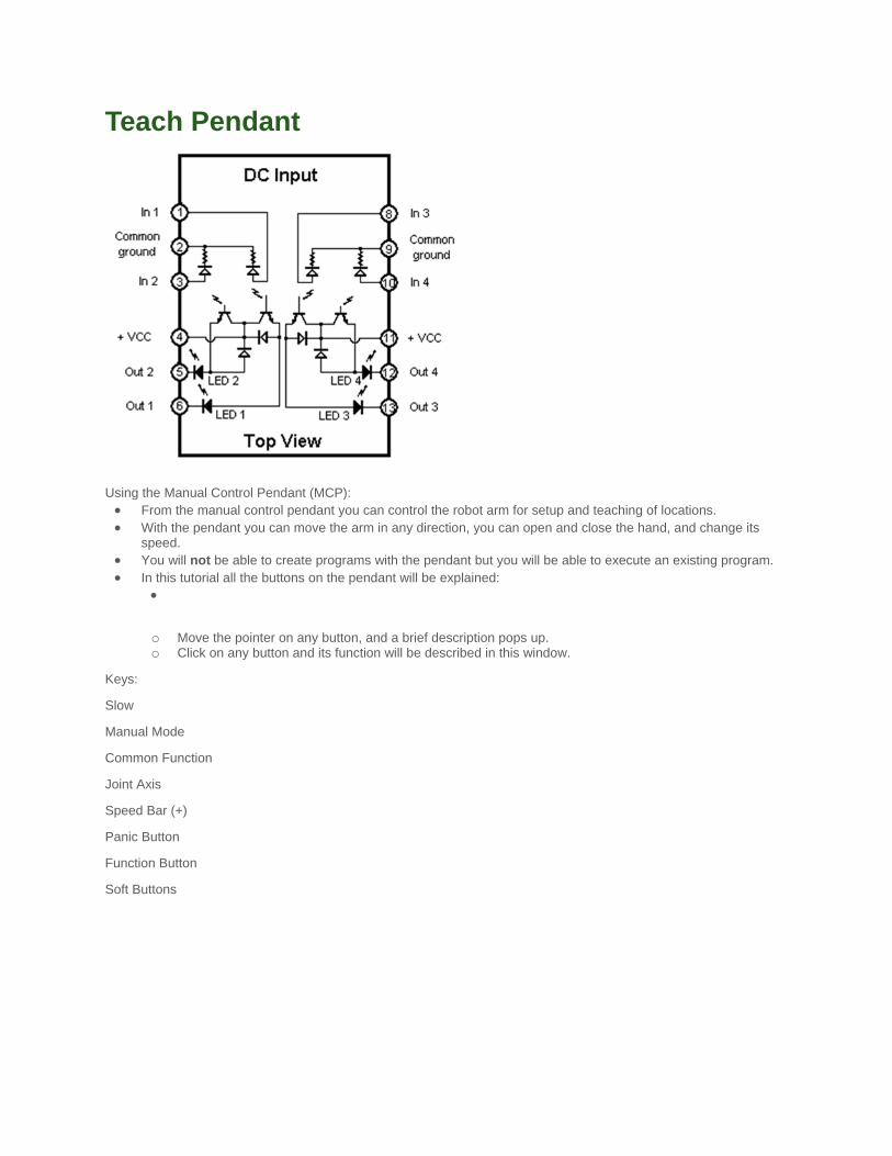
Binary I/O The following diagrams show brief examples of the connections between the I/O connector and an external peripheral
device.
Figure 8: Connections for digital input (white) modules
The DC input modules are Adept part number 15400-00010, model IDC5Q. The input voltage ranges are: 10 to 32
VDC or 15 to 32 VAC. Input impedance is 1000 W.
Figure 9: Connections for digital output (red) modules

The DC output modules are Adept part number 15400-00013, model ODC5Q. The operating voltage range is 5 to 60
VDC, 3 A max.
Figure 10: Connections between I/O modules and plugs 1. Connector (plug) handles input signals 1001 to 1008;
2. Connector (plug) handles input signals 1009 to 1016;
3. Connector (plug) handles output signals 17 to 24;
4. Connector (plug) handles output signals 25 to 32;
Several cables are provided for interfacing external devices to the I/O modules. There are four connectors in the back
of the Adept controller, labeled I, I, O, and O. Figure 10 (above) shows the pin-outs for these connectors. Tabes 1
and 2 show the wire colors and pin connections for the existing cables. Two cables are available to carry two input or
output signals each (depending on the connectors the cables are plugged in) and two other cables can handle up to
five input or output signals each.
Table 1: Three (3) conductor cables
signal name for programming
wire color Plug 1 (I) Plug 2 (I) Plug 3 (O) Plug 4(O)
black common common common common
white 1001 1009 17 25

red 1002 1010 18 26
Table 2: Seven (7) conductor cables
signal name for programming
wire color Plug 1 (I) Plug 2 (I) Plug 3 (O) Plug 4 (O)
black common 1 common 1 common 1 common 1
white 1001 1009 17 25
red 1002 1010 18 26
blue 1003 1011 19 27
green common 2 common 2 common 2 common 2
brown 1005 1013 21 29
orange 1006 1014 22 30

Shut-down This chapter applies to students who will be working with the robot in the lab. When you have accessed the robot via
the WEB the remote control program for the robot will remain active after you terminate your session.
At the end of your lab session the computer and robot system must be shut down properly to avoid damage to the
equipment. 1. Using ProComm issue one last command to turn off power to the servo motors of the Adept robot, type:
1. .disable power<CR> 2. Next turn off power to the controller from the front panel switch; 3. Terminate the ProComm program on the computer, type:
1. <ALT>X
<ENTER>
to exit from ProComm.
4. Shutdown Windows using established procedures. 5. Turn off power to the computer on the power strip.