filtra-mvss (multimvss (multi venturi scrubber system)– superior nozzle design, most efficient...
TRANSCRIPT

© 2012 Westinghouse Electric Company LLC. All Rights Reserved.Westinghouse Non-Proprietary Class 3
FILTRA-MVSS (Multi VenturiFILTRA-MVSS (Multi VenturiScrubber System)Presentation to U.S. NRC, Washington DCOctober 11, 2012
Per Olof NilssonPer Olof Nilsson
Westinghouse Electric Company
1

© 2012 Westinghouse Electric Company LLC. All Rights Reserved.Westinghouse Non-Proprietary Class 3
Agenda● Historical background
Agenda
● New System Design● Filtering Technology● Qualification of FILTRA MVSS● Qualification of FILTRA-MVSS● Sizing assessment regarding severe scenarios● Stress Test Conclusions● Conclusions
2

© 2012 Westinghouse Electric Company LLC. All Rights Reserved.Westinghouse Non-Proprietary Class 3
Multi Venturi Scrubber (Liner Version) 1988 design1988 designA: Pressure relief line from reactor containmentB: Venturi distribution systemyC: Venturis including riser pipeD: PoolE: Moisture separatorF: Release to atmosphereF: Release to atmosphereG: Pressure VesselH: ManholeI: Liner
The Swedish FILTRA – MVSS is located outside the reactor building in a concrete pressure vessel equipped with a liner.
Th t b thThe concrete serves as both a pressure retaining structure and shielding. A gravel bed is used as moisture separator due to the sturdy design requirement.
3

© 2012 Westinghouse Electric Company LLC. All Rights Reserved.Westinghouse Non-Proprietary Class 3
Installed in both PWRs and BWRs• Equally suitable for both
PWR d BWR
Installed in both PWRs and BWRs
PWR and BWR• Excellent design features
for both types
4

© 2012 Westinghouse Electric Company LLC. All Rights Reserved.Westinghouse Non-Proprietary Class 3
FILTRA MVSS Proven awarded designFILTRA-MVSS - Proven, awarded design
Awarded the prestigious Swedish Polhemprize for high-level technological innovationLennart Gustavsson and Leif Lindau
SS f f
Awarded the prestigious Swedish Polhemprize for high-level technological innovationLennart Gustavsson and Leif Lindau
SS f fFILTRA-MVSS, safety system for nuclear reactorsFILTRA-MVSS, safety system for nuclear reactors
5

© 2012 Westinghouse Electric Company LLC. All Rights Reserved.Westinghouse Non-Proprietary Class 3
Swedish Requirements for Installed SystemsSystems
Design Basis Station black-out
Design requirementsPassive system for at least 24 hHigh decontamination factor for aerosol and elementary iodineCover a wide range of hypothetical severe accidents for BWR’s and PWR’sCover a wide range of hypothetical severe accidents for BWR s and PWR s
OperationAutomatic or Manual activation (allows early venting)
6

© 2012 Westinghouse Electric Company LLC. All Rights Reserved.Westinghouse Non-Proprietary Class 3
FILTRA-MVSS, New system design1 t ti d 2 d ti d i
New version of the FILTRA-MVSS system:Liner version Steel tank version
Metal fiber filter (sintered) added
for improved performance
1st generation and 2nd generation design
Demister moved inside vessel with standard components of less
weight and size
performance (<0,8 µm)
2nd Generation
Same venturi system
8,5 m -10,5m
Same venturi system, changes related only to vessel
7 m
7

© 2012 Westinghouse Electric Company LLC. All Rights Reserved.Westinghouse Non-Proprietary Class 3
FILTRA-MVSS, New System Design O ll i t
Steel tank allowing pressurization to reduce sizeEasily adjustable to NPP unit needs (size weight DF)
Overall improvements
Easily adjustable to NPP unit needs (size, weight, DF)Standard demister with less weight, moved inside tankMetal fiber filter (sintered) in series to increase DF and capture even smaller particleseven smaller particlesShortened installation time since tank and venturi now is manufactured independent from building.Tank and internals verified for seismic loads provided in pthe Design SpecificationNo change in venturi design, it is verified for the new conditions and requirements and has solid base for li ilicensing
8

© 2012 Westinghouse Electric Company LLC. All Rights Reserved.Westinghouse Non-Proprietary Class 3
FILTRA-MVSS, Filtering technologyP i i l f d t i ti i MVSS t iKey physical and chemical separation processes• Particle separation in multi-venturi nozzles:
Principles of decontamination in a MVSS venturi
Particle separation in multi venturi nozzles:1 thiosulfate solution
2 aerosols2 aerosols
v ~ 100 m/s
i) adapting mass flow ii) velocity difference at throat iii) inertial particulate separation
• Pool scrubbing of aerosols and elemental iodine
v2 v10
• Pool scrubbing of aerosols and elemental iodine– Reinforced aerosol separation in the pool
– S2O32- (thiosulphate) chemical absorption of Elemental Iodine (I2 ):
9

© 2012 Westinghouse Electric Company LLC. All Rights Reserved.Westinghouse Non-Proprietary Class 3
FILTRA-MVSS, Filtering technologyC i t ti l t i t
CONVENTIONAL VENTURI :
Comparison to conventional venturi system
• Fan to pump gas for pressure drop• Pump to supply liquid• Active control device (variable throttle) for gas capacity control
MVSS is PASSIVE:• Uses vertical pipe length water column as pressure drop• Uses inlet gas acceleration under pressure suction to pump liquid into gas for uniform coverage• Uses sloping pipe water lock as optimal gas capacity control• Uses pool bubbling as additional gas absorption step and as scrubbing drop collector• Results confirm DF is independent of operating conditions and given by total pressure drop:at
all conditions the same DF was obtainedall conditions, the same DF was obtained
MVSS venturi design was developed based on classic venturi
10
ptheory - verified by testing

© 2012 Westinghouse Electric Company LLC. All Rights Reserved.Westinghouse Non-Proprietary Class 3
FILTRA-MVSS, Filtering technology K iti l l t f filt ti
● Step 1 High DF for aerosols– Keep aerosol mass (=decay heat) from accumulating in later steps
Key critical elements of filtration
– Keep aerosol mass (=decay heat) from accumulating in later steps– Must not clog
● Step 2 Efficiently retain and cool captured aerosols– Must have coolant enough to not dry out during passive period– Captured aerosols must not accumulate to create hot spots that may lead to
damages– Efficiently retain and cool captured aerosol and iodine by
chemical bonding to sodium thiosulphate in waterchemical bonding to sodium thiosulphate in water● Step 3 Prevent contaminated droplets from
leaving the scrubber– Must not be clogged by water or two phase foam Step 3
Step 4
gg y p● Step 4 High DF for small aerosols
– Fiber filters should only receive small amounts ofaerosols to prevent melt between repeated venting.Must not clog Step 1
Step 2
11
– Must not clog p

© 2012 Westinghouse Electric Company LLC. All Rights Reserved.Westinghouse Non-Proprietary Class 3
FILTRA-MVSS, Filtering technologyFilt t 1 V t i
● High efficient venturi scrubbing
Filter step 1 - Venturi
– DF > 1000 for aerosols so that all fission products are kept in water– Prevents fiber filter step from large decay heat– Superior nozzle design, most efficient water scrubber function– Efficient scrubbing of elemental iodine
● Independent of ventilated flow– Same excellent DF within design flow range– Genius flow distribution activates necessary number of venturi– Allows venting from low containment pressure, start from 7 psi (g)
● No risk for clogging or hotspotsNo risk for clogging or hotspots– No narrow passages that collects particles– Venturi pipes in robust design made of 316L stainless steel
12

© 2012 Westinghouse Electric Company LLC. All Rights Reserved.Westinghouse Non-Proprietary Class 3
FILTRA-MVSS, Filtering technologyFilt t 1 V t i d i k t f DF
From ACE - test report
Filter step 1 - Venturi design a key parameter for DF
0 m
m26
00
1000
mm
500
mm
DF particles is given by total pressure drop between the venturi throat and the MVSSOther supplier
long tube
Other suppliershort tube
riser pipe outletHighest pressure drop for MVSS (height of 2600 mm) other suppliers (500 mm and 1000 mm)
13
A tall venturi pipe is important for a high DF
for particles

© 2012 Westinghouse Electric Company LLC. All Rights Reserved.Westinghouse Non-Proprietary Class 3
FILTRA-MVSS, Filtering technologyFilt t 1 V t i d i k t f DF
Estimated DF particles from established design rules and ML/MG 1 - 3
Filter step 1 - Venturi design a key parameter for DF
The FILTRA-MVSS venturis are performing ~10
Emperical relation betweenthe cut size (the aerodynamicparticle diameter having 50% collection efficiency )and theventuri pressure drop
Integrated total DF as a function of cutdiameter
Design Height Total Venturi D50% DF DF DF
times better than nozzles used in other wet filtered scrubber systems
(m) dp(kPa)
dp(kPa)
Aerod(µm)
MMD*=1.5 (µm)
MMD*=1 (µm)
MMD*=0.5 (µm)
MVSS 2.6 26 25 0.2 1100 400 150
Other supplierLong tube
1 10 9 0.35 110 60 9
Other supplierShort tube
0.5 5 4 0.5 60 30 2
14
*MMD= GMMD=Geometrical Mass Median Diameter based on the particle size distribution with respect to particle geometrical diameter

© 2012 Westinghouse Electric Company LLC. All Rights Reserved.Westinghouse Non-Proprietary Class 3
FILTRA-MVSS, Filtering technology Filt t 2 W t i i
● Contributes to total aerosol filter efficiency with DF>2
Filter step 2 - Water mixing
● Large free water volume– Sized to allow long passive period of collect and retain active fission
products– Efficiently decay heat removal from retained aerosols with internal
heat exchanger sized for venting during extended SBO● Elemental Iodine removal● Elemental Iodine removal
– Sodium thiosulphate Increases total DF of Iodine with fast chemical reactions
– Large water volume can dissolve and retain large quantities of– Large water volume can dissolve and retain large quantities of Iodine
Large amount of water gives best overall system
15
gives best overall system functionality
© 2012 Westinghouse Electric Company LLC. All Rights Reserved.Westinghouse Non-Proprietary Class 3
FILTRA-MVSS, Filtering technology Filt t 3 D i t
● Verified functionality
Filter step 3 - Demister
● Verified functionality – Tested in laboratory for all related conditions– Reduces more than 97% of droplets
N ll i f i d l i d d l d b– No collection of contaminated aerosols, rinsed and cooled by steam
● Dependable design in 316L stainless steel– Mounting inside tank and verified seismic together with stress analyses for
tank and all other internals
● Accessible for service and inspection– Contributes to total DF
16

© 2012 Westinghouse Electric Company LLC. All Rights Reserved.Westinghouse Non-Proprietary Class 3
FILTRA-MVSS, Filtering technologyFilt t 4 M t l Fib Filt (Si t d)
● Used for small particles with size less than 0,8 μm● Modular design particle holding capacity and differential pressure is
Filter step 4 - Metal Fiber Filter (Sintered)
● Modular design, particle holding capacity and differential pressure is decided by the number of filter elements
● Extensive laboratory testing for HEPA quality● Dependable design in 316L stainless steel● Dependable design in 316L stainless steel● Mounted inside tank and verified seismic together with stress analyses for
tank and all other internals● No loose parts, by-pass after seismic chock not possibleNo loose parts, by pass after seismic chock not possible● Accessible for service and inspection● Contributes to total DF > 10000
Protected from large decay heat collection by efficient venturi filter step 1
17

© 2012 Westinghouse Electric Company LLC. All Rights Reserved.Westinghouse Non-Proprietary Class 3
FILTRA-MVSS, Filtering technologyFilt t 4 O ti l t l fib filt (Si t d)Filter step 4 - Optional metal fiber filter (Sintered)
Tank top with filter elements installed
Experience • Fifty-eight installations in Europe• Four installations in China (two under manufacture)
• Two units - delivered in 2002Two units - scheduled for delivery the end of January 2013
Media pack construction of the proposed filter – end fittings and dimensions according to plant specific demand
18
plant specific demand

© 2012 Westinghouse Electric Company LLC. All Rights Reserved.Westinghouse Non-Proprietary Class 3
FILTRA-MVSS, Qualification Process V t i V ifi ti P M d l b ildiExperiments under near prototypical conditions with controlled scaling using proven chemical engineering scaling laws and detailed modelling
Venturi Verification Process - Model building
The venturi model has been modularized and each step has beenvalidated by experiments
St 1
using proven chemical engineering scaling laws and detailed modelling
● Step 1– Two-phase modelling of flow in each venturi lab testing
Drop size modellinglab testing– Drop size modellinglab testing
– Particle collection (DF) modellinglab testing
– Transient behaviour evaluationlab testing– Transient behaviour evaluationlab testing● Step 2, Full scale dynamic test. Pool behaviour● Step 3, Advanced Containment Experiments
19
© 2012 Westinghouse Electric Company LLC. All Rights Reserved.Westinghouse Non-Proprietary Class 3
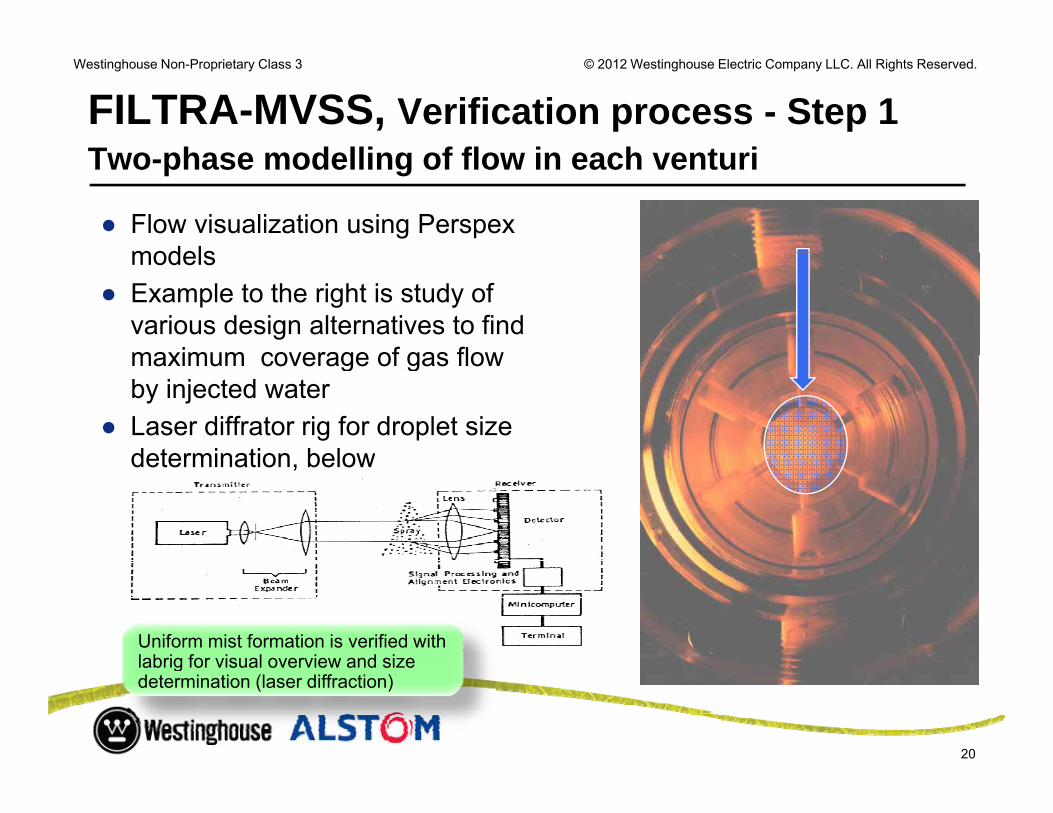
FILTRA-MVSS, Verification process - Step 1T h d lli f fl i h t i
● Flow visualization using Perspex models
Two-phase modelling of flow in each venturi
models● Example to the right is study of
various design alternatives to findmaximum coverage of gas flowmaximum coverage of gas flow by injected water
● Laser diffrator rig for droplet sizedetermination belowdetermination, below
Uniform mist formation is verified with labrig for visual overview and size
20
labrig for visual overview and size determination (laser diffraction)

© 2012 Westinghouse Electric Company LLC. All Rights Reserved.Westinghouse Non-Proprietary Class 3
FILTRA-MVSS, Verification process - Step 1P ti l ll ti d lli
● DF model is based on classic venturi theory*● Single drop collection mechansim is mainly Impaction of particles in high velocity flow
Particle collection modelling
Single drop collection mechansim is mainly Impaction of particles in high velocity flow around droplets
● Impaction controlled by dimensionless Stokes number, K● This gives expression
C =Cunningham slip correctionρ= particle densityv= gas velocity
Fractional DF = DF(particle size) = f (K, ML/MG) (K=Cּρּd2ּv/9ּμּD)
● Result integrated over all venturis and over all particle sizes for total DF
μ = gas dynamic viscosityD = drop sized= particle size
Result integrated over all venturis and over all particle sizes for total DF
*”Venturi Scrubber Performance Model”, USEPA 1977 Rep. No. 600/2-77-172
21

© 2012 Westinghouse Electric Company LLC. All Rights Reserved.Westinghouse Non-Proprietary Class 3
FILTRA-MVSS, Verification process - Step 1P ti l ll ti d lliParticle collection modelling
Concluded test aerosolAndersen
QCM
Specified by supplier
AndersenQCM
● Redispersed ”Minusil” (silica) arerosol
– MMD = 1.5µm– Ρ = 4000 kg/m3 – Distribution = σ2
● Impactor measurements confirmthat aerodynamic size distributionthat aerodynamic size distribution is prototypical
● Measured with impactorsAndersen method (chosen method)– Andersen method (chosen method)
– QCM method
22
*MMD= GMMD=Geometrical Mass Median Diameter based on the particle size distribution with respect to particle geometrical diameter
© 2012 Westinghouse Electric Company LLC. All Rights Reserved.Westinghouse Non-Proprietary Class 3
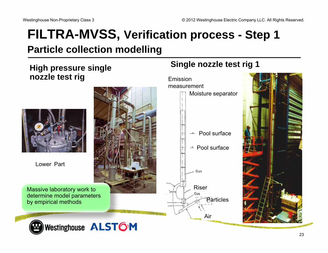
FILTRA-MVSS, Verification process - Step 1P ti l ll ti d lli
Emission
Single nozzle test rig 1Particle collection modelling
High pressure single nozzle test rig Emission
measurementMoisture separator
nozzle test rig
Pool surface
Pool surface
Lower Part
Particles
RiserMassive laboratory work to determine model parameters by empirical methods
23
Air

© 2012 Westinghouse Electric Company LLC. All Rights Reserved.Westinghouse Non-Proprietary Class 3
FILTRA-MVSS, Verification process - Step 2F ll l d i t tFull scale dynamic test
● Performed at Forsmark 2, 1988– Full size FILTRA test after installed in Forsmark
● Verify transient pressure and water levels for different gas mass flows
– Transient behavior of water after rupture disc break
● Rupture disc break at 780 kPa (abs)● Rupture disc break at 780 kPa (abs)– Ackumulator tank filled with compressed air
● Max inlet pressure 460 kPa (abs)– Pressure rise to remove water from tubes
Aft l th 10 d l diff i filt– After less then 10 seconds only pressure difference in filter was due to water level in tank
– According to calculations
● Max. water level +0,6-0,7m– Water density lower (volume increase) during “bubble phase”y ( ) g p– According to calculations
24

© 2012 Westinghouse Electric Company LLC. All Rights Reserved.Westinghouse Non-Proprietary Class 3
FILTRA-MVSS, Verification process - Step 3 ACE verificationACE verification
• Advanced Containment ExperimentsP f d i th C t i t S t F ilit (CTF) H f d E i i• Performed in the Containment Systems Facility (CTF), Hanford EngineeringDevelopment Laboratory, U.S.
L b t RiLaboratory RigACE Participants:
ABB/Westinghouse(Wet)YIT/WestinghouseYIT/Westinghouse (Dry)Areva/Siemens(Wet)Edf (Dry)Russia (Wet)
Aerosol generator
( )
25
FILTRA -MVSS

© 2012 Westinghouse Electric Company LLC. All Rights Reserved.Westinghouse Non-Proprietary Class 3
FILTRA-MVSS, Verification process - Step 3 ACE-verification summary of resultsACE-verification, summary of results
• Aerosol with AMMD*= 2µm, sigma=2
M d DF• Measured DFs:Aerosol 1% steam 40%
steamDF Cs 25000 31000DF I 19000 54000DF Mn 1500 1500
• Overall DF Mn same as calculated
• Cs and I components interaction with steam improves DF with a factor of the order of 15factor of the order of 15
Terminology explanation: *AMMD = Aerodynamic Mass Median Diameter = SQRT(particle density) x diameter
26

© 2012 Westinghouse Electric Company LLC. All Rights Reserved.Westinghouse Non-Proprietary Class 3
FILTRA-MVSS, Stress testR lt f S d 2011Result from Sweden 2011
Beneficial Filter system“One strength of the Swedish NPP are that all reactors are 2 Nov 2011gequipped with filtering systems, preventing release of radioactive particles in the event of a severe accident.
The filters was installed as a lesson learned from the Three MilesThe filters was installed as a lesson learned from the Three Miles Island accident.
The system considerably reduces the consequences to the y y qenvironment in case of a severe accident. If a release occurs the filters contribute to only releasing very small amounts of radioactive materials.”
Jan Hanberg, head of section at the Swedish Radiation Safety Authority
27

© 2012 Westinghouse Electric Company LLC. All Rights Reserved.Westinghouse Non-Proprietary Class 3
FILTRA-MVSS, Stress testR lt f S it l d 2012Result from Switzerland 2012
P bli h d J 2012
Available at :http://www.ensi.ch/en/2012/01/10/eu-stress-test-swiss-national-report-online/.
Published January 2012
•KernKraftWerk Leibstadt, KKL, GE BWR with 2 CCI scrubber tanks installed•KernKraftWerk Goesgen, KKG, KWU PWR with a AREVA scrubber installed.•KernKraftWerk Muhleberg KKM, GE BWR with FILTRA-MVSS installed. NO REMARKS
28

© 2012 Westinghouse Electric Company LLC. All Rights Reserved.Westinghouse Non-Proprietary Class 3
Summary Advantages of FILTRA MVSSSummary Advantages of FILTRA-MVSS● Designed for SBO filtered venting ● High and same DF over entire flow range – independent of vent flow● High and same DF over entire flow range independent of vent flow● Completely passive (no manual actions, no power, no additional water)
for at least 24 h● High decay heat capacity of captured filtered material no need for extra● High decay heat capacity of captured filtered material, no need for extra
water storage tanks● Verified for very tough seismic loads● Modular delivery for ease of installation● Modular delivery for ease of installation● May be used for long term cooling of molten core decay heat (feed &
bleed) Independent Vent ri s stem /metal filter for Safet● Independent Venturi system /metal filter for Safety
– With postulated failure of the metal filter, 99% mass fraction of contaminant are still removed
● DF after each filtration stage is known
29
● DF after each filtration stage is known

© 2012 Westinghouse Electric Company LLC. All Rights Reserved.Westinghouse Non-Proprietary Class 3
Thank you for your attentiony y
30

© 2012 Westinghouse Electric Company LLC. All Rights Reserved.Westinghouse Non-Proprietary Class 3
Backup SlidesBackup Slides
31

© 2012 Westinghouse Electric Company LLC. All Rights Reserved.Westinghouse Non-Proprietary Class 3
FILTRA-MVSS, Filtering technologyS bbi t h l lScrubbing technology, generalThe Non-Nuclear Global Industrial Experience:● For industrial gas cleaning processes, since 100 years, one scrubber principle is used for g g p , y , p p
high performance particle material removal: Venturi scrubber. ● Cleaning filters are used for particulate removal from dry gases and scrubber systems are
used for wet gases.
● Nuclear accident venting gas is hot with varying flow, contains steam, has both large and small particles, has hygroscopic material, and noxious gas components. Conditions are similar to gas cleaning from electric arc furnaces or other thermal processes.
● Venturi scrubbers have moderate gas absorption capacity (must be chemical reinforced)
● For gas component removal: packed tower, spray tower and bubbling bed.
● Packed towers are not used on gases with high particle content due to risk of clogging.
FILTRA-MVSS manage to solve the different filtering problems in a single solution
32

© 2012 Westinghouse Electric Company LLC. All Rights Reserved.Westinghouse Non-Proprietary Class 3
FILTRA-MVSS, Filtering technology V t i bbi i i l l
Venturi nozzle step-by-step1. Gas carrying aerosols enters from top
Venturi scrubbing principal, general
y g p2. Liquid is added to gas wall 3. Gas is accelerated in throat 4. Water is atomized to a droplet mist in the throat
W d l h l l i d5. Water droplets have slower velocity compared to gas and particles and will ”glue” particles that come close
6. To ensure high velocity in venturi a variable throttle is normally used, MVSS have a more intelligent system
7. Scrubbing drops are collected in water tank and separated from gas
Systems without above features cannot be provedas venturi collector.
FILTRA-MVSS has a clearly proven venturi design
33
© 2012 Westinghouse Electric Company LLC. All Rights Reserved.Westinghouse Non-Proprietary Class 3
FILTRA-MVSS, New System Design A ti t f ti f th t i t
● Regular sampling, to ensure good water quality and thereforeequipment durability:
Actions to ensure a safe operation of the venturi system
equipment durability:– Values measured :
– PH & Concentration of Thio-sulphate & Sulfide– Concentration, type & size of mechanical dirts– Obscurity of the liquid phase– Concentration of some additives such as biocide
– Only one chemical adjustment made during 24 years of operation on Swedish MVSS.
● Sampled boroscopic (fiber optics) inspection of tubes made from a platforminside the tank
– Periodical– When water quality measurements reveals unusual values.
● Every filter step is fully accessable for service and inspection, total filterefficency is possible to maintain within filter system lifetime
34

© 2012 Westinghouse Electric Company LLC. All Rights Reserved.Westinghouse Non-Proprietary Class 3
Historical Background● 1979 Three Mile Island
1981 Filt d C t i t V til ti (FCV) d i i i S d
Historical Background
● 1981 Filtered Containment Ventilation (FCV) decision in Sweden● 1985 10.000 cubic meter gravel filter installed at:
– Barsebäck 1 and 2(1986 Ch b l)● (1986 Chernobyl)
● 1988 New requirements on pressure relief stipulated by the Swedish Government
– Cs release limited to 0 1% of core inventoryCs release limited to 0.1% of core inventory
● 1988 FILTRA - MVSS (Multi Venturi Scrubber System) installed at: – Oskarshamn 1, 2 and 3– Forsmark 1, 2 and 3Forsmark 1, 2 and 3– Ringhals 1, 2, 3 and 4
35

© 2012 Westinghouse Electric Company LLC. All Rights Reserved.Westinghouse Non-Proprietary Class 3
Design parameters for BWR and PWR, 1988 diti1988 conditions
BWR PWR ● Gas mass flow 0,1 – 13 kg/sg● Gas composition Steam
N2, H2O2 (PWR)
● Gas temperature 70 – 150 C● Rupture disc opening pressure 0,5 – 0,6 MPa● Earthquake, ground acceleration 0,15 g● Operation 0 – 8 h totally passive
8 – 24 h manual action> 24 h improvisation
DF (aerosols)* 100/500 500/1500● DF (aerosols) 100/500 500/1500● DF (iodine)* 100/500 500/1500● Hydrogen combustion Sturdy design
Physical separation Preferred
36
● Physical separation Preferred
* guarantee/design

© 2012 Westinghouse Electric Company LLC. All Rights Reserved.Westinghouse Non-Proprietary Class 3
FILTRA-MVSS, New System Design S i i bilit t k d i t l
● Steel tank and interior equipment (including demister and MFF) is exposed to
Seismic capability, tank and internals
(including demister and MFF) is exposed to – Seismic loads– Sloshing loads
FEM b d l ti l ti t ASME III● FEM based evaluation relative to ASME III
Steel tank as well as interior equipment will withstand very high Seismic loads
37

© 2012 Westinghouse Electric Company LLC. All Rights Reserved.Westinghouse Non-Proprietary Class 3
FILTRA-MVSS, Filtering technology I di filt i Ch i l b ti f l t l i di
Experimentally determined:
Iodine filtering - Chemical absorption of elemental iodine
Solubility of I2 gas into water is low (0.2 g/l) .Thiosulfate ions speeds up reaction :
I2 +2S2O3 -- S4O6
-- + 2I- (fast reaction kinetic)Dissolution rate is also increased by the reaction :
I2 + I- I 3-2 3
Followed by:I3
- +2S2O3 -- S4O6
-- + 3I-Thiosulfate concentration about 0.01 mol/lThiosulfate concentration about 0.01 mol/l PH adjusted to > 10.5 to minimize thiosulfate oxidation
Reaction rate will increase very much with
38
yincreasing temperature and pressure

© 2012 Westinghouse Electric Company LLC. All Rights Reserved.Westinghouse Non-Proprietary Class 3
FILTRA-MVSS, Verification process - Step 1P ti l ll ti d lliParticle collection modelling
Single drop target effeciencyg p g yfor particle collection vs. Stoke´s number .
In the present work, theIn the present work, the Calvert (curve 6 in the graph) expression is used.
The venturi model has a strong
Literature: SPS Gas Cleaning Manual Volume 3, Wet Dedusting, 1987
The venturi model has a strong base from classic venturi theori
39

© 2012 Westinghouse Electric Company LLC. All Rights Reserved.Westinghouse Non-Proprietary Class 3
FILTRA-MVSS, Verification process V ifi ti O tli f MVSSExperiments under near prototypical conditions with controlled scaling using proven chemical engineering scaling laws and own
Verification process Outline of MVSS
g g p g g gmodelling
Parameter Tested range Unit Remarks
Modelling and model validation: Parameter Tested range Unit Remarks
Venturi gas throat velocity 40 -115 m/s
Liquid mass flow/ gas mass flow (ML/MG) 1-4 -
Gas density (air) 1.5-7 kg/m3 Saturated steam :14 bara = 7.1 kg/m3
Gas pressure (air) ~1.3-6 bara
System temperature 10-80 °C Water temperatuer in the tank y p pduring the test.
Particle size range for the total and fractionalDF
0.1 -4 µm DF (particle size)= DF fractional
Varying pool height (above riser pipe) 0.1-3
40

© 2012 Westinghouse Electric Company LLC. All Rights Reserved.Westinghouse Non-Proprietary Class 3
FILTRA-MVSS, Verification process - Step 3 ACE-verification pool scrubbingACE-verification, pool scrubbing
Contribution to total DF from bubble phasefrom bubble phase
Analytical model predicts conservative DF for all elements
41
Particle size (µm)

© 2012 Westinghouse Electric Company LLC. All Rights Reserved.Westinghouse Non-Proprietary Class 3
FILTRA-MVSS, sizing assessmentM k II 2000 kW 26 k / @ 2 d T k di 5 5Mark II, 2000 kW; 26 kg/s @ 2pd; Tank dia. 5,5m
Mass balance and tank water level during an accident for a Mark II, 2000 kW heat load•Time 0h: Start point of venting•Time 0h: Start point of venting. •Time 1h: The water level increases due to condensed steam and pool swelling•Time 1h-24h: The water level decreases, same high filter efficiency remain•Time 24h: FILTRA-MVSS design is robust and a high DF remain at 24 hours.
Water should be added
2000 kW
0h 1h 8h 16h 24hDF in scr bber after 24 h ill be 1000
42
DF in scrubber after 24 h will be ≈1000 but total system DF will be >10000 due to metal fiber filter. Minimal amount of aerosols expected after 24 h

© 2012 Westinghouse Electric Company LLC. All Rights Reserved.Westinghouse Non-Proprietary Class 3
FILTRA-MVSS, LicensingS d iSweden experience
● In Sweden the implementation of Severe Accident Mitigation features, including Filtered Containment Venting System were proceeded by aincluding Filtered Containment Venting System, were proceeded by a governmental requirement.
● Technical requirements were developed via interaction between Regulatory body utilities and vendorRegulatory body, utilities and vendor
– Suitable severe accident analysis tools– Selection of design basis events
Developments of emergency operating procedures– Developments of emergency operating procedures– Acceptable releases after a severe accident
Licensing of FILTRA-MVSS was a part of the licensing of all Severe Accident Mitigation featuresAccident Mitigation features
43
© 2012 Westinghouse Electric Company LLC. All Rights Reserved.Westinghouse Non-Proprietary Class 3
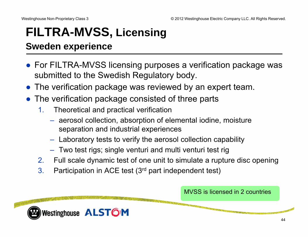
FILTRA-MVSS, LicensingS d iSweden experience
● For FILTRA-MVSS licensing purposes a verification package was submitted to the Swedish Regulatory bodysubmitted to the Swedish Regulatory body.
● The verification package was reviewed by an expert team. ● The verification package consisted of three parts
1. Theoretical and practical verification – aerosol collection, absorption of elemental iodine, moisture
separation and industrial experiences– Laboratory tests to verify the aerosol collection capability– Two test rigs; single venturi and multi venturi test rig
2. Full scale dynamic test of one unit to simulate a rupture disc openingy p p g3. Participation in ACE test (3rd part independent test)
MVSS is licensed in 2 countries
44
MVSS is licensed in 2 countries