final draft european telecommunication … · this ets has been produced in order to provide...
TRANSCRIPT

FINAL DRAFT
EUROPEAN pr ETS 300 417-2-1
TELECOMMUNICATION January 1997
STANDARD
Source: ETSI TC-TM Reference: DE/TM-01015-2-1
ICS: 33.020
Key words: Transmission, SDH, interface
Transmission and Multiplexing (TM);Generic requirements of transport
functionality of equipment;Part 2-1: Synchronous Digital Hierarchy (SDH) and
Plesiochronous Digital Hierarchy (PDH)physical section layer functions
ETSI
European Telecommunications Standards Institute
ETSI Secretariat
Postal address: F-06921 Sophia Antipolis CEDEX - FRANCEOffice address: 650 Route des Lucioles - Sophia Antipolis - Valbonne - FRANCEX.400: c=fr, a=atlas, p=etsi, s=secretariat - Internet: [email protected]
Tel.: +33 4 92 94 42 00 - Fax: +33 4 93 65 47 16
Copyright Notification: No part may be reproduced except as authorized by written permission. The copyright and theforegoing restriction extend to reproduction in all media.
© European Telecommunications Standards Institute 1997. All rights reserved.

Page 2Final draft prETS 300 417-2-1: January 1997
Whilst every care has been taken in the preparation and publication of this document, errors in content,typographical or otherwise, may occur. If you have comments concerning its accuracy, please write to"ETSI Editing and Committee Support Dept." at the address shown on the title page.
Page 3Final draft prETS 300 417-2-1: January 1997
Contents
Foreword .......................................................................................................................................................7
1 Scope ..................................................................................................................................................9
2 Normative references..........................................................................................................................9
3 Definitions, abbreviations and symbols .............................................................................................113.1 Definitions ..........................................................................................................................113.2 Abbreviations .....................................................................................................................113.3 Symbols and diagrammatic conventions ...........................................................................153.4 Introduction ........................................................................................................................15
4 STM-1 Optical Section Layer Functions............................................................................................174.1 Optical Section Connection functions ................................................................................174.2 Optical Section Trail Termination functions .......................................................................18
4.2.1 Optical Section Trail Termination Source OS1-Xy.z_TT_So ........................184.2.2 Optical Section Trail Termination Sink OS1-Xy.z_TT_Sk.............................19
4.3 Optical Section Adaptation functions .................................................................................214.3.1 Optical Section to Regenerator Section Adaptation Source
OS1/RS1_A_So ............................................................................................214.3.2 Optical Section to Regenerator Section Adaptation Sink OS1/RS1_A_Sk ...22
5 STM-4 Optical Section Layer Functions............................................................................................245.1 Optical Section Connection functions ................................................................................245.2 Optical Section Trail Termination functions .......................................................................25
5.2.1 Optical Section Trail Termination Source OS4-Xy.z_TT_So ........................255.2.2 Optical Section Trail Termination Sink OS4-Xy.z_TT_Sk.............................26
5.3 Optical Section Adaptation functions .................................................................................275.3.1 Optical Section to Regenerator Section Adaptation Source
OS4/RS4_A_So ............................................................................................275.3.2 Optical Section to Regenerator Section Adaptation Sink OS4/RS4_A_Sk ...28
6 STM-16 Optical Section Layer Functions..........................................................................................306.1 Optical Section Connection functions ................................................................................306.2 Optical Section Trail Termination functions .......................................................................31
6.2.1 Optical Section Trail Termination Source OS16-Xy.z_TT_So ......................316.2.2 Optical Section Trail Termination Sink OS16-Xy.z_TT_Sk...........................32
6.3 Optical Section Adaptation functions .................................................................................336.3.1 Optical Section to Regenerator Section Adaptation Source
OS16/RS16_A_So ........................................................................................336.3.2 Optical Section to Regenerator Section Adaptation Sink
OS16/RS16_A_Sk.........................................................................................34
7 STM-64 Optical Section Layer Functions..........................................................................................36
8 STM-1 Electrical Section Layer Functions ........................................................................................368.1 STM-1 Electrical Section Connection function ES1_C ......................................................368.2 STM-1 Electrical Section Trail Termination functions........................................................37
8.2.1 STM-1 Electrical Section Trail Termination Source ES1_TT_So..................378.2.2 STM-1 Electrical Section Trail Termination Sink ES1_TT_Sk ......................38
8.3 STM-1 Electrical Section Adaptation functions..................................................................398.3.1 STM-1 Electrical Section to Regenerator Section Adaptation Source
ES1/RS1_A_So.............................................................................................398.3.2 STM-1 Electrical Section to Regenerator Section Adaptation Sink
ES1/RS1_A_Sk .............................................................................................40

Page 4Final draft prETS 300 417-2-1: January 1997
9 E4 Section Layer Functions.............................................................................................................. 429.1 E4 Connection function E4_C ........................................................................................... 439.2 E4 Trail Termination functions .......................................................................................... 44
9.2.1 E4 Trail Termination Source E4_TT_So....................................................... 449.2.2 E4 Trail Termination Sink E4_TT_Sk ........................................................... 45
9.3 E4 Adaptation functions .................................................................................................... 469.3.1 E4 to P4x Adaptation Source E4/P4x_A_So ................................................ 469.3.2 E4 to P4x Adaptation Sink E4/P4x_A_Sk..................................................... 479.3.3 E4 to P4e Adaptation Source E4/P4e_A_So................................................ 499.3.4 E4 to P4e Adaptation Sink E4/P4e_A_Sk .................................................... 509.3.5 E4 to P4s Adaptation Source E4/P4s_A_So ................................................ 529.3.6 E4 to P4s Adaptation Sink E4/P4s_A_Sk..................................................... 53
10 E31 Section Layer Functions............................................................................................................ 5610.1 E31 Connection function E31_C ....................................................................................... 5710.2 E31 Trail Termination functions ........................................................................................ 58
10.2.1 E31 Trail Termination Source E31_TT_So................................................... 5810.2.2 E31 Trail Termination Sink E31_TT_Sk ....................................................... 59
10.3 E31 Adaptation functions .................................................................................................. 6010.3.1 E31 to P31x Adaptation Source E31/P31x_A_So ........................................ 6010.3.2 E31 to P31x Adaptation Sink E31/P31x_A_Sk............................................. 6110.3.3 E31 to P31e Adaptation Source E31/P31e_A_So........................................ 6310.3.4 E31 to P31e Adaptation Sink E31/P31e_A_Sk ............................................ 6410.3.5 E31 to P31s Adaptation Source E31/P31s_A_So ........................................ 6610.3.6 E31 to P31s Adaptation Sink E31/P31s_A_Sk............................................. 67
11 E22 Section Layer Functions............................................................................................................ 7011.1 E22 Connection function E22_C ....................................................................................... 7111.2 E22 Trail Termination functions ........................................................................................ 72
11.2.1 E22 Trail Termination Source E22_TT_So................................................... 7211.2.2 E22 Trail Termination Sink E22_TT_Sk ....................................................... 73
11.3 E22 Adaptation functions .................................................................................................. 7411.3.1 E22 to P22x Adaptation Source E22/P22x_A_So ........................................ 7411.3.2 E22 to P22x Adaptation Sink E22/P22x_A_Sk............................................. 7511.3.3 E22 to P22e Adaptation Source E22/P22e_A_So........................................ 7711.3.4 E22 to P22e Adaptation Sink E22/P22e_A_Sk ............................................ 78
12 E12 Section Layer Functions............................................................................................................ 8012.1 E12 Connection function E12_C ....................................................................................... 8112.2 E12 Trail Termination functions ........................................................................................ 82
12.2.1 E12 Trail Termination Source E12-Z_TT_So ............................................... 8212.2.2 E12 Trail Termination Sink E12-Z_TT_Sk.................................................... 84
12.3 E12 Adaptation functions .................................................................................................. 8512.3.1 E12 to P12x Adaptation Source E12/P12x_A_So ........................................ 8512.3.2 E12 to P12x Adaptation Sink E12/P12x_A_Sk............................................. 8612.3.3 E12 to P12s Adaptation Source E12/P12s_A_So ........................................ 8812.3.4 E12 to P12s Adaptation Sink E12/P12s_A_Sk............................................. 89
13 T12 Section Layer Functions ............................................................................................................ 9113.1 T12 Connection function T12_C ....................................................................................... 9113.2 T12 Trail Termination functions ........................................................................................ 92
13.2.1 T12 Trail Termination Source T12-Z_TT_So ............................................... 9213.2.2 T12 Trail Termination Sink T12-Z_TT_Sk.................................................... 93
13.3 T12 Adaptation functions .................................................................................................. 9413.3.1 T12 to SD Adaptation Source T12/SD_A_So............................................... 9413.3.2 T12 to SD Adaptation Sink T12/SD_A_Sk ................................................... 94
14 E0 Section Layer Functions.............................................................................................................. 9514.1 E0 Connection function E0_C ........................................................................................... 9514.2 E0 Trail Termination functions .......................................................................................... 96
14.2.1 E0 Trail Termination Source E0_TT_So....................................................... 9614.2.2 E0 Trail Termination Sink E0_TT_Sk ........................................................... 97
14.3 E0 Adaptation functions .................................................................................................... 98
Page 5Final draft prETS 300 417-2-1: January 1997
14.3.1 E0 to P0s Adaptation Source E0/P0s_A_So.................................................9814.3.2 E0 to P0s Adaptation Sink E0/P0s_A_Sk .....................................................99
Annex A (informative): E32 Section Layer Functions............................................................................101
A.1 E32 Connection function E32_C .....................................................................................................101
A.2 E32 Trail Termination functions ......................................................................................................102A.2.1 E32 Trail Termination Source E32_TT_So......................................................................102A.2.2 E32 Trail Termination Sink E32_TT_Sk ..........................................................................103
A.3 E32 Adaptation functions ................................................................................................................104A.3.1 E32 to P32x Adaptation Source E32/P32x_A_So ...........................................................104A.3.2 E32 to P32x Adaptation Sink E32/P32x_A_Sk................................................................105
Annex B (Informative): E11 Section Layer Functions............................................................................107
B.1 E11 Connection function E11_C .....................................................................................................107
B.2 E11 Trail Termination functions ......................................................................................................108B.2.1 E11 Trail Termination Source E11_TT_So......................................................................108B.2.2 E11 Trail Termination Sink E11_TT_Sk ..........................................................................109
B.3 E11 Adaptation functions ................................................................................................................110B.3.1 E11 to P11x Adaptation Source E11/P11x-L_A_So ........................................................110B.3.2 E11 to P11x Adaptation Sink E11/P11x-L_A_Sk.............................................................111
Annex C (informative): Bibliography......................................................................................................113
History........................................................................................................................................................114

Page 6Final draft prETS 300 417-2-1: January 1997
Blank page
Page 7Final draft prETS 300 417-2-1: January 1997
Foreword
This final draft European Telecommunication Standard (ETS) has been produced by the Transmissionand Multiplexing (TM) Technical Committee of the European Telecommunications Standards Institute(ETSI), and is now submitted for the Voting phase of the ETSI standards approval procedure.
This ETS has been produced in order to provide inter-vendor and inter-operator compatibility for transportfunctionality of equipment.
This ETS consists of 8 parts as follows:
Part 1: "Generic processes and performance" (ETS 300 417-1-1 [1]);
Part 2: "SDH and PDH physical section layer functions" (ETS 300 417-2-1);
Part 3: "STM-N regenerator and multiplex section layer functions" (ETS 300 417-3-1);
Part 4: "SDH path layer functions" (ETS 300 417-4-1);
Part 5: "PDH path layer functions" (ETS 300 417-5-1);
Part 6: "Synchronization distribution layer functions" (ETS 300 417-6-1);
Part 7: "Auxiliary layer functions" (DE/TM-01015-7-1);
Part 8: "Compound and major compound functions" (DE/TM-01015-8-1).
Proposed transposition dates
Date of latest announcement of this ETS (doa): 3 months after ETSI publication
Date of latest publication of new National Standardor endorsement of this ETS (dop/e): 6 months after doa
Date of withdrawal of any conflicting National Standard (dow): 6 months after doa

Page 8Final draft prETS 300 417-2-1: January 1997
Blank page
Page 9Final draft prETS 300 417-2-1: January 1997
1 Scope
This European Telecommunication Standard (ETS) specifies a library of basic building blocks and a set ofrules by which they are combined in order to describe transport functionality of equipment. The librarycomprises the functional building blocks needed to completely specify the generic functional structure ofthe European transmission hierarchies. Equipment which is compliant with this ETS needs to bedescribable as an interconnection of a subset of these functional blocks contained within this ETS. Theinterconnections of these blocks need to obey the combination rules given. The generic functionality isdescribed in the ETS 300 417-1-1 [1].
2 Normative references
This ETS incorporates by dated or undated reference, provisions from other publications. Thesenormative references are cited at the appropriate places in the text and the publications are listedhereafter. For dated references subsequent amendments to, or revisions of, any of these publicationsapply to this ETS only when incorporated in it by amendments or revisions. For undated references thelatest edition of the publication referred to applies.
[1] ETS 300 417-1-1: "Transmission and Multiplexing (TM); Generic functionalrequirements for Synchronous Digital Hierarchy (SDH) equipment; Part 1-1:Generic processes and performance".
[2] ETS 300 337: "Transmission and Multiplexing (TM); Generic frame structuresfor the transport of various signals (including Asynchronous Transfer Mode(ATM) cells and Synchronous Digital Hierarchy (SDH) elements) at theCCITT Recommendation G.702 hierarchical rates of 2 048 kbit/s, 34 368 kbit/sand 139 264 kbit/s".
[3] ETS 300 167 (1993): "Transmission and Multiplexing (TM); Functionalcharacteristics of 2 048 kbit/s interfaces".
[4] ETS 300 147: "Transmission and Multiplexing (TM); Synchronous DigitalHierarchy (SDH) Multiplexing structure".
[5] ETS 300 166 (1993): "Transmission and Multiplexing (TM); Physical andelectrical characteristics of hierarchical digital interfaces for equipment using the2 048 kbit/s - based plesiochronous or synchronous digital hierarchies".
[6] ETS 300 232 (1993): "Transmission and Multiplexing (TM); Optical interfaces forequipments and systems relating to the Synchronous DigitalHierarchy [ITU-T Recommendation G.957 (1993) modified]".
[7] ITU-T Recommendation G.751 (1988): "Digital multiplex equipments operatingat the third order bit rate of 34 368 kbit/s and the fourth order bit rate of139 264 kbit/s and using positive justification".
[8] ITU-T Recommendation G.742 (1988): "Second order digital multiplexequipment operating at 8 448 kbit/s and using positive justification".
[9] ITU-T Recommendation G.823 (1993): "The control of jitter and wander withindigital networks which are based on the 2 048 kbit/s hierarchy".
[10] ITU-T Recommendation G.775 (1994): "Loss of signal (LOS) and alarmindication signal (AIS) defect detection and clearance criteria".
[11] ITU-T Recommendation G.703 (1991): "Physical/electrical characteristics ofhierarchical digital interfaces".
[12] ITU-T Recommendation G.958 (1994): "Digital line systems based on thesynchronous digital hierarchy for use on optical fibre cables".

Page 10Final draft prETS 300 417-2-1: January 1997
[13] ANSI T1.102 (1993): "Telecommunications - Digital Hierarchy - ElectricalInterfaces".
[14] ANSI T1.107 (1988): "Telecommunications - Digital Hierarchy - FormatsSpecifications".
[15] ITU-T Recommendation G.825: "The control of jitter and wander within digitalnetworks which are based on the synchronous digital hierarchy (SDH)".
[16] prETS 300 417–6–1: "Transmission and Multiplexing (TM); Genericrequirements of transport functionality of equipment; Part 6-1: Synchronizationdistribution layer functions".

Page 11Final draft prETS 300 417-2-1: January 1997
3 Definitions, abbreviations and symbols
3.1 Definitions
The functional definitions are described in ETS 300 417-1-1 [1].
3.2 Abbreviations
For the purposes of this ETS, the following abbreviations apply:
A Adaptation functionAcSL Accepted Signal LabelAcTI Accepted Trace identifierADM Add-Drop MultiplexerAI Adapted InformationAIS Alarm Indication SignalALS Automatic Laser ShutdownANSI American National Standards InstituteAP Access PointAPId Access Point IdentifierAPS Automatic Protection SwitchATM Asynchronous Transfer ModeAU Administrative UnitAUG Administrative Unit GroupAU-n Administrative Unit, level nBBE Background Block ErrorBBER Background Block Error RatioBER Bit Error RatioBFA Basic Frame AlignmentBIP Bit Interleaved ParityBIP-N Bit Interleaved Parity, width NBITS Building Integrated Timing SupplyBNF Backus-Naur FormBSHR Bi-directional Self Healing RingC Connection functionCH CHannelCI Characteristic InformationCID Consecutive Identical DigitsCK ClockCM Connection MatrixCMI Coded Mark InversionCo ConnectionCP Connection PointCRC Cyclic Redundancy CheckCRC-N Cyclic Redundancy Check, width NCs supervisory-unequipped Connection functionCSES Consecutive Severely Errored SecondsCTF Compound Timing FunctionCtrl ControlD DataDCC Data Communications ChannelDEC DECrementDEG DEGradedDEGTHR DEGraded THResholdDL Data LinkDPRING Dedicated PRotection RINGDROP Decreased Received Optical PowerDXC Digital Cross ConnectE0 Electrical interface signal 64 kbit/sE11 Electrical interface signal 1 544 kbit/sE12 Electrical interface signal 2 048 kbit/sE22 Electrical interface signal 8 448 kbit/sE31 Electrical interface signal 34 368 kbit/s

Page 12Final draft prETS 300 417-2-1: January 1997
E32 Electrical interface signal 44 736 kbit/sE4 Electrical interface signal 139 264 kbit/sEBC Errored Block CountECC Embedded Communications ChannelECC(x) Embedded Communications Channel, Layer xEDC Error Detection CodeEDCV Error Detection Code ViolationEFS Equipment Functional SpecificationEMF Equipment Management FunctionEPS Equipment Protection SwitchEQ EquipmentERS Elementary Regenerator SectionES Electrical SectionES Errored SecondESR Errored seconds RatioEx CCITT Recommendation G.703 [11] type electrical signal, bit rate order xExSL Expected Signal LabelExTI Expected Trace IdentifierF_B Far-end BlockF_BBE Far-end Background Block ErrorF_DS Far-end Defect SecondF_EBC Far-end Errored Block CountF_ES Far-end Errored SecondF_SES Far-end Severely Errored SecondF_SESTHR Far-end Severely Errored Second ThresholdF_UAT_cmd Far-end UnAvailable Time commandFAS Frame Alignment SignalFEBE Far End Block ErrorFERF Far End Receive FailureFIFO First In First OutFIT Failure In TimeFO Frame Offset informationFOP Failure Of ProtocolFS Frame Start signalHDB3 High Density Bipolar of order 3HDLC High-level Data Link Control procedureHO Higher OrderHOVC Higher Order Virtual ContainerHP Higher order PathID IdentifierIF In Frame stateINC IncrementIOS Intra-Office SectionIS Intermediate SystemISDN Integrated Services Digital NetworkISO International Standardization OrganizationITU-T International Telecommunications Union- Telecommunications SectorLAN Local Area NetworkLBC Laser Bias CurrentLC Link ConnectionLLC Logical Link ControlLMC Laser Modulation CurrentLO Lower OrderLOA Loss Of Alignment; generic for LOF, LOM, LOPLOF Loss Of FrameLOM Loss Of MultiframeLOP Loss Of PointerLOS Loss Of SignalLOT Loss of Octet TimingLOVC Lower Order Virtual ContainerLPx Lower order Path for VC-x (x = 11, 12, 2, 3)LT Line TerminationM&CF Management & Communication Function

Page 13Final draft prETS 300 417-2-1: January 1997
MC Matrix ConnectionMCF Message Communications FunctionMDT Mean Down Timemei maintenance event informationMI Management InformationMO Managed ObjectMON MonitoredMP Management PointMS Multiplex SectionMS1 STM-1 Multiplex SectionMS16 STM-16 Multiplex SectionMS4 STM-4 Multiplex SectionMSB Most Significant BitMSOH Multiplex Section OverheadMSP Multiplex Section ProtectionMSPG Multiplex Section Protection GroupMTBF Mean Time Between FailuresMTTR Mean Time To RepairN.C. Not ConnectedN_B Near-end BlockN_BBE Near-end Background Block ErrorN_DS Near-end Defect SecondN_EBC Near-end Errored Block CountN_ES Near-end Errored SecondN_SES Near-end Severely Errored SecondN_SESTHR Near-end Severely Errored Second ThresholdN_UAT_cmd Near-end UnAvailable Time commandNC Network ConnectionNCM No CRC-4 Multiframe alignment signalNDF New Data FlagNE Network ElementNMON Not MonitoredNNI Network Node InterfaceNPDU Network Protocol Data UnitNRZ Non-Return to ZeroNRZI Non-Return to Zero InvertedNSAP Network Service Access PointNU National Use (bits, bytes)NUx National Use, bit rate order xOAM Operation, Administration and ManagementOFS Out of Frame SecondOOF Out Of Frame stateOS Operations SystemOS Optical SectionOSC OscillatorOSI(x) Open Systems Interconnection, Layer xOW Order WireP ProtectionP_A Protection AdaptationP_C Protection ConnectionP_TT Protection Trail TerminationP0_31c 1 984 kbit/s layerP0s synchronous 64 kbit/s layerP11x 1 544 kbit/s layer (transparent)P12s 2 048 kbit/s PDH path layer with synchronous 125 µs frame structure according
to ETS 300 167 [3]P12x 2 048 kbit/s layer (transparent)P22e 8 448 kbit/s PDH path layer with 4 plesiochronous 2 048 kbit/sP22x 8 448 kbit/s layer (transparent)P31e 34 368 kbit/s PDH path layer with 4 plesiochronous 8 448 kbit/sP31s 34 368 kbit/s PDH path layer with synchronous 125 µs frame structure
according to ETS 300 337 [2]P31x 34 368 kbit/s layer (transparent)

Page 14Final draft prETS 300 417-2-1: January 1997
P32x 44 736 kbit/s layer (transparent)P4e 139 264 kbit/s PDH path layer with 4 plesiochronous 34 368 kbit/sP4s 139 264 kbit/s PDH path layer with synchronous 125 µs frame structure
according to ETS 300 337 [2]P4x 139 264 kbit/s layer (transparent)PDC Photo Diode CurrentPDH Plesiochronous Digital HierarchyPJE Pointer Justification EventPLM Payload MismatchPM Performance MonitoringPn Plesiochronous signal, Level nPOH Path OverheadPRC Primary Reference ClockPS Protection SwitchingPSC Protection Switch CountPSV Power Supply VoltagePTR PointerPU PDH UnitQOS Quality Of ServiceRDI Remote Defect IndicatorREI Remote Error IndicatorRI Remote InformationRLT Regenerated Line TerminationRP Remote PointRS Regenerator SectionRS1 STM-1 Regenerator SectionRS16 STM-16 Regenerator SectionRS4 STM-4 Regenerator SectionRSOH Regenerator Section OverheadRTG Regenerator Timing GeneratorRTR Reset Threshold ReportRxSL Received Signal LabelRxTI Received Trace identifierS11 VC-11 path layerS12 VC-12 path layerS2 VC-2 path layerS3 VC-3 path layerS4 VC-4 path layerSASE Stand-Alone Synchronization EquipmentSD Synchronization Distribution layer, Signal DegradeSD-2 2 048 kbit/s based timing source referenceSDA Synchronization Distribution AdaptationSD-C 2 048 kHz based timing source referenceSDH Synchronous Digital HierarchySD-N STM-N based timing source referenceSDT Synchronization Distribution TerminationSEC SDH Equipment ClockSES Severely Errored SecondSESR Severely Errored seconds RatioSF Signal FailSHR Self Healing RingSk SinkSLM Signal Label MismatchSMF Sub-Multi FrameSMUX Synchronous MultiplexerSNC Sub-Network ConnectionSNC/I Inherently monitored Sub-Network Connection protectionSNC/N Non-intrusively monitored Sub-Network Connection protectionSo SourceSOH Section OverheadSPRING Shared Protection RingSSD Server Signal DegradeSSF Server Signal Fail

Page 15Final draft prETS 300 417-2-1: January 1997
SSM Synchronization Status MessageSSU Synchronization Supply UnitSTM Synchronous Transport ModuleSTM-N Synchronous Transport Module, level NT12 2 048 kHz signalTCA Threshold Crossing AlertTCF Timing Connection FunctionTCN Threshold Crossing NotificationTCP Termination Connection PointTD Transmit DegradeTF Transmit FailTFAS trail Trace identifier Frame Alignment SignalTG Timing GeneratorTI Timing InformationTIM Trace Identifier MismatchTM Transmission_Medium, Transmission & MultiplexingTMN Telecommunications Management NetworkTP Timing PointTPmode Termination Point modeTPS Transmission Protection SwitchTR Threshold ReportTS Time SlotTSD Trail Signal DegradeTSF Trail Signal FailTSL Trail Signal LabelTT Trail Termination functionTTI Trail Trace IdentifierTTP Trail Termination PointTTs Trail Termination supervisory functionTU Tributary UnitTUG Tributary Unit GroupTUG-m Tributary Unit Group, level mTU-m Tributary Unit, level mTxSL Transmitted Signal LabelTxTI Transmitted Trace IdentifierUAS UnAvailable SecondUAT UnAvailable TimeUAT_cmd UnAvailable Time commandUF Unit FailureUI Unit IntervalUNEQ UnequippedUNI User to Network InterfaceURLT Unregenerated Line TerminationUSR User channelsUVC Unequipped VCVC Virtual ContainerVC-n Virtual Container, level nVMR Violation Monitoring and RemovalVP Virtual PathW Working
3.3 Symbols and diagrammatic conventions
The symbols and diagrammatic conventions are described in ETS 300 417-1-1 [1].
3.4 Introduction
The atomic functions defining the physical interface section layers are described below. They describe thephysical and logical characteristics of the optical and electrical interfaces used in SDH equipments alsowith their adaptation functionality of PDH multiplex equipments described in the ITU-T RecommendationsG.751 [7] and G.742 [8] for signal hierarchies P4, P31 and P22, and adaptation functionality for SDH overPDH specified by ETS 300 337 [2] for signal hierarchies P4s and P31s and ETS 300 167 [3] for P12slayer signals.

Page 16Final draft prETS 300 417-2-1: January 1997
The physical interface layers are defined for each of the synchronous and plesiochronous rates as definedin ETS 300 147 [4] and ETS 300 166 [5]. References to the signal structure are mentioned in theappropriate text sections.

Page 17Final draft prETS 300 417-2-1: January 1997
4 STM-1 Optical Section Layer Functions
OS1-Xy.z
OS1/RS1
RS1_CI
OS1_AI
OS1_CI
OS1-Xy.z
OS1/RS1
OS1_AI
RS1_CI
OS1_CI
OS1
OS1_CIOS1_CI
NOTE: Xy.z will be one value out of the set: I1, S1.1, S1.2, L1.1, L1.2, L1.3.
Figure 1: STM-1 Optical Section atomic functions
STM-1 Optical Section Layer CP
Characteristic Information OS1_CI of the optical layer CP (figure 2) is a digital, optical signal of definedpower, bit rate, pulse width and wavelength. A range of such characteristic signals for different opticalpower budgets is defined in ETS 300 232 [6].
1 2 3 4 5 6 7 8 9 10 .... 2701 A1 A1 A1 A2 A2 A22345 scrambled STM-1 bytes6789
Figure 2: OS1 characteristic information OS1_CI (optical) and adapted informationOS1_AI (electrical)
STM-1 Optical Section Layer AP
The information passing across the OS1 AP takes the form of a scrambled, digital bitstream (including ablock frame character at 125 µs intervals) with co-directional bit timing (figure 2). Frame characters andthe synchronous, scrambling polynomial are defined in ETS 300 147 [4].
4.1 Optical Section Connection functions
For further study.

Page 18Final draft prETS 300 417-2-1: January 1997
4.2 Optical Section Trail Termination functions
4.2.1 Optical Section Trail Termination Source OS1-Xy.z_TT_So
NOTE 1: Xy.z will be one value out of the set: I1, S1.1, S1.2, L1.1, L1.2, L1.3.
Symbol:
OS1-Xy.z
OS1_AI
OS1_CI
O S 1_T T _S o_M I X: I,S,Ly: 1z: 1,2,3
Figure 3: OS1-Xy.z_TT_So symbol
Interfaces:
Table 1: OS1-Xy.z_TT_So input and output signals
Input(s) Output(s)OS1_AI_D OS1_CI_D
OS1_TT_So_MI_cTDOS1_TT_So_MI_cTF
Processes:
This function forms the optical STM-1 signal for transmission over the optical cable as defined inETS 300 232 [6].
Optical characteristics: The function shall generate an optical STM-1 signal that meets the Xy.zcharacteristics defined in ETS 300 232 [6].
Defects:
dTD, dTF:
NOTE 2: Degraded signal implies that the output although still operational has fallen belowsome threshold of acceptability which requires maintenance intervention. The definitionof the acceptability will in general be specific to a particular design or maintenancephilosophy and is not defined in this ETS. The defects are equipment specific.
Consequent Actions: None.
Defect Correlations:
cTF ← dTF
cTD ← dTD and (not dTF)
Performance Monitoring: None.
Page 19Final draft prETS 300 417-2-1: January 1997
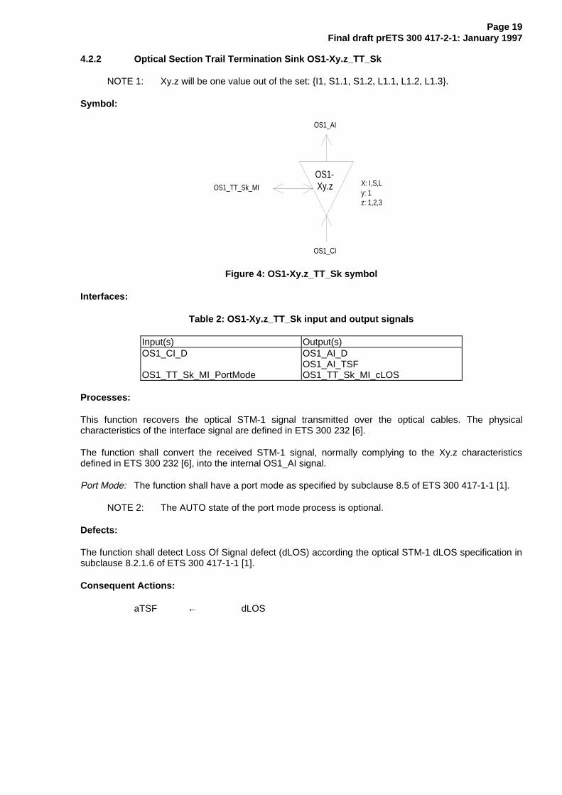
4.2.2 Optical Section Trail Termination Sink OS1-Xy.z_TT_Sk
NOTE 1: Xy.z will be one value out of the set: I1, S1.1, S1.2, L1.1, L1.2, L1.3.
Symbol:
OS1-Xy.z
OS1_AI
OS1_CI
OS1_TT_Sk_MI X: I,S,Ly: 1z: 1,2,3
Figure 4: OS1-Xy.z_TT_Sk symbol
Interfaces:
Table 2: OS1-Xy.z_TT_Sk input and output signals
Input(s) Output(s)OS1_CI_D
OS1_TT_Sk_MI_PortMode
OS1_AI_DOS1_AI_TSFOS1_TT_Sk_MI_cLOS
Processes:
This function recovers the optical STM-1 signal transmitted over the optical cables. The physicalcharacteristics of the interface signal are defined in ETS 300 232 [6].
The function shall convert the received STM-1 signal, normally complying to the Xy.z characteristicsdefined in ETS 300 232 [6], into the internal OS1_AI signal.
Port Mode: The function shall have a port mode as specified by subclause 8.5 of ETS 300 417-1-1 [1].
NOTE 2: The AUTO state of the port mode process is optional.
Defects:
The function shall detect Loss Of Signal defect (dLOS) according the optical STM-1 dLOS specification insubclause 8.2.1.6 of ETS 300 417-1-1 [1].
Consequent Actions:
aTSF ← dLOS

Page 20Final draft prETS 300 417-2-1: January 1997
Defect Correlations:
cLOS ← MON and dLOS
Performance Monitoring: None.

Page 21Final draft prETS 300 417-2-1: January 1997
4.3 Optical Section Adaptation functions
4.3.1 Optical Section to Regenerator Section Adaptation Source OS1/RS1_A_So
Symbol:
OS1/RS1
RS1_CI
OS1_AI
Figure 5: OS1/RS1_A_So symbol
Interfaces:
Table 3: OS1/RS1_A_So input and output signals
Input(s) Output(s)RS1_CI_DRS1_CI_CK
OS1_AI_D
Processes: None.
The function shall not add any jitter.
NOTE: Jitter at the NNI is the combination of the jitter generated and transferred via the clientlayers.
Defects: None.
Consequent Actions: None.
Defect Correlations: None.
Performance Monitoring: None.

Page 22Final draft prETS 300 417-2-1: January 1997
4.3.2 Optical Section to Regenerator Section Adaptation Sink OS1/RS1_A_Sk
Symbol:
OS1/RS1
RS1_CI
OS1_AI
OS1/RS1_A_Sk_MI
Figure 6: OS1/RS1_A_Sk symbol
Interfaces:
Table 4: OS1/RS1_A_Sk input and output signals
Input(s) Output(s)OS1_AI_DOS1_AI_TSF
OS1/RS1_A_Sk_MI_1second
RS1_CI_DRS1_CI_CKRS1_CI_FSRS1_CI_SSFOS1/RS1_A_Sk_MI_cLOFOS1/RS1_A_Sk_MI_pOFS
Processes:
This function regenerates the received signal, recovers bit timing (CK) and frame start reference (FS)from the received signal.
Regeneration: The function shall operate with a maximum BER as specified in ETS 300 417-1-1 [1],subclause 11.3.2.1 when any combination of the following signal conditions exist at the input:
- any input optical power level within the range specified in ETS 300 232 [6];
- jitter modulation applied to the input signal as specified in ETS 300 417-1-1 [1],subclause 11.3.2.1;
- the input signal bit rate has any value in the range 155 520 kbit/s ± 20 ppm.
NOTE: The frequency and jitter/wander tolerance might be further constrained by therequirements of the client layers.
To ensure adequate immunity against the presence of consecutive identical digits (CID) in the STM-1signal, the function shall comply with the specification in ITU-T Recommendation G.958 [12], section 7.4.
The function shall process the signal such that in the absence of input jitter, the intrinsic jitter at the STM-1output interface (in a regenerative repeater) shall not exceed:
- 0,5 UI peak-to-peak when measured through a bandpass filter with corner frequencies at 500 Hzand 1,3 MHz and low pass roll off of 60 dB/decade and high pass roll off of 20 dB/decade;
- 0,1 UI peak-to-peak when measured through a bandpass filter with corner frequencies at 65 kHzand 1,3 MHz and low pass roll off of 60 dB/decade and high pass roll off of 20 dB/decade.
The function shall process the signal such that the jitter transfer (measured between an STM-1 input andSTM-1 output in a regenerative repeater) shall be as specified in ITU-T Recommendation G.958 [12],section 9.3.2, Type A.

Page 23Final draft prETS 300 417-2-1: January 1997
Frame alignment: The frame alignment shall be found by searching for the A1, A2 bytes contained in theSTM-1 signal. The framing pattern searched for may be a subset of the A1 and A2 bytes contained on theSTM-1 signal. The frame signal shall be continuously checked with the presumed frame start position forthe alignment. If in the In-Frame state (IF), the maximum Out-Of-Frame (OOF) detection time shall be625 µs for a random unframed signal. The algorithm used to check the alignment shall be such that,under normal conditions, a 10-3 (Poisson type) error ratio will not cause a false OOF more then once per6 minutes. If in the OOF state, the maximum frame alignment time shall be 250 µs for an error-free signalwith no emulated framing patterns. The algorithm used to recover from the OOF state shall be such , thatthe probability for false frame recovery with a random unframed signal shall be no more than 10-5 per250 µs time interval.
In F ram e(IF)
O ut O f F ram e(O O F )
m ax 5 E rro red F A S s
2 E rro r F ree F A S s
Figure 7: Frame alignment process
The frame start signal (RS1_CI_FS) shall be maintained during the OOF state and only updated uponsuccessful transition form OOF to the IF state.
Defects:
If the OOF anomaly persists for 3 ms, a STM-1 Loss Of Frame defect (dLOF) shall be detected. Toprovide for the case of intermittent OOFs, the integrating timer shall not be reset to zero until an IFcondition persists continuously for 3 ms. The dLOF defect shall be cleared when the IF state persistscontinuously for 3 ms.
Loss Of FrameCleared
(dLOF=false)
Loss Of FrameSet
(dLOF=true)
Out Of Frame for >3ms
In Frame for >3ms
NOTE: Out-Of-Frame integrating timer is not reset to zero until an In-Frame condition persistscontinuously for 3 ms.
Figure 8: Loss of frame process
Consequent Actions:
aAIS ← dLOF or AI_TSF
aSSF ← dLOF or AI_TSF
On declaration of an aAIS the function shall output an all-ONEs (AIS) signal - complying to the frequencylimits for this interface - within 250 µs; on clearing of aAIS the function shall output normal data within250 µs.
Defect Correlations:
cLOF ← dLOF and (not AI_TSF)
Performance Monitoring:
Any second with at least one OOF event shall be reported as an pOFS (Out of Frame Second).

Page 24Final draft prETS 300 417-2-1: January 1997
5 STM-4 Optical Section Layer Functions
NOTE: Xy.z will be one value out of the set: I4, S4.1, S4.2, L4.1, L4.2, L4.3.
OS4-Xy.z
OS4/RS4
RS4_CI
OS4_AI
OS4_CI
OS4-Xy.z
OS4/RS4
OS1_AI
RS4_CI
OS4_CI
OS4
OS4_CIOS4_CI
Figure 9: STM-4 Optical Section atomic functions
STM-4 Optical Section Layer CP
Characteristic Information OS4_CI of the optical layer CP (figure 10) is a digital, optical signal of definedpower, bit rate, pulse width and wavelength. A range of such characteristic signals for different opticalpower budgets is defined in ETS 300 232 [6].
1
2
3
4
5
6
7
8
9
1 2 3 4 5 6 7 8 9 10 11 12 13 14 15 16 17 18 19 20 21 22 23 24 25 26 27 28 29 30 31 32 33 34 35 36 37 1080
scrambled STM-4 bytes
A1 A1 A1 A1 A1 A1 A1 A1 A1 A1 A1A1 A2 A2 A2 A2 A2 A2 A2 A2 A2 A2 A2 A2
Figure 10: OS4 characteristic information OS4_CI (optical) and adapted information OS4_AI(electrical)
STM-4 Optical Section Layer AP
The information passing across the OS4 AP takes the form of a scrambled, digital bitstream (including ablock frame character at 125 µs intervals) with co-directional bit timing (figure 10). Frame characters andthe synchronous, scrambling polynomial are defined in ETS 300 147 [4].
5.1 Optical Section Connection functions
For further study.

Page 25Final draft prETS 300 417-2-1: January 1997
5.2 Optical Section Trail Termination functions
5.2.1 Optical Section Trail Termination Source OS4-Xy.z_TT_So
NOTE 1: Xy.z will be one value out of the set: I4, S4.1, S4.2, L4.1, L4.2, L4.3.
Symbol:
OS4-Xy.z
OS4_AI
OS4_CI
O S 4_T T _S o_M I X: I,S,Ly: 4z: 1,2,3
Figure 11: OS4-Xy.z_TT_So symbol
Interfaces:
Table 5: OS4-Xy.z_TT_So input and output signals
Input(s) Output(s)OS4_AI_D OS4_CI_D
OS4_TT_So_MI_cTDOS4_TT_So_MI_cTF
Processes:
This function forms the optical STM-4 signal for transmission over the optical cable as defined inETS 300 232 [6].
Optical characteristics: The function shall generate an optical STM-4 signal that meets the Xy.zcharacteristics defined in ETS 300 232 [6].
Defects:
dTD, dTF:
NOTE 2: Degraded signal implies that the output although still operational has fallen belowsome threshold of acceptability which requires maintenance intervention. The definitionof the acceptability will in general be specific to a particular design or maintenancephilosophy and is not defined in this ETS. The defects are equipment specific.
Consequent Actions: None.
Defect Correlations:
cTF ← dTF
cTD ← dTD and (not dTF)
Performance Monitoring: None.

Page 26Final draft prETS 300 417-2-1: January 1997
5.2.2 Optical Section Trail Termination Sink OS4-Xy.z_TT_Sk
NOTE 1: Xy.z will be one value out of the set: I4, S4.1, S4.2, L4.1, L4.2, L4.3.
Symbol:
OS4-Xy.z
OS4_AI
OS4_CI
OS4_TT_Sk_MI X: I,S,Ly: 4z: 1,2,3
Figure 12: OS4-Xy.z_TT_Sk symbol
Interfaces:
Table 6: OS4-Xy.z_TT_Sk input and output signals
Input(s) Output(s)OS4_CI_D
OS4_TT_Sk_MI_PortMode
OS4_AI_DOS4_AI_TSFOS4_TT_Sk_MI_cLOS
Processes:
This function recovers the optical STM-4 signal transmitted over the optical cables. The physicalcharacteristics of the interface signal are defined in ETS 300 232 [6].
The function shall convert the received STM-4 signal, normally complying to the Xy.z characteristicsdefined in ETS 300 232 [6], into the internal OS4_AI signal.
Port Mode: The function shall have a port mode as specified by subclause 8.5 of ETS 300 417-1-1 [1].
NOTE 2: The AUTO state of the port mode process is optional.
Defects:
The function shall detect Loss Of Signal defect (dLOS) according the optical STM-4 dLOS specification insubclause 8.2.1.6 of ETS 300 417-1-1 [1].
Consequent Actions:
aTSF ← dLOS
Defect Correlations:
cLOS ← MON and dLOS
Performance Monitoring: None.

Page 27Final draft prETS 300 417-2-1: January 1997
5.3 Optical Section Adaptation functions
5.3.1 Optical Section to Regenerator Section Adaptation Source OS4/RS4_A_So
Symbol:
OS4/RS4
RS4_CI
OS4_AI
Figure 13: OS4/RS4_A_So symbol
Interfaces:
Table 7: OS4/RS4_A_So input and output signals
Input(s) Output(s)RS4_CI_DRS4_CI_CK
OS4_AI_D
Processes: None.
The function shall not add any jitter.
NOTE: Jitter at the NNI is the combination of the jitter generated and transferred via the clientlayers."
Defects: None.
Consequent Actions: None.
Defect Correlations: None.
Performance Monitoring: None.
Page 28Final draft prETS 300 417-2-1: January 1997
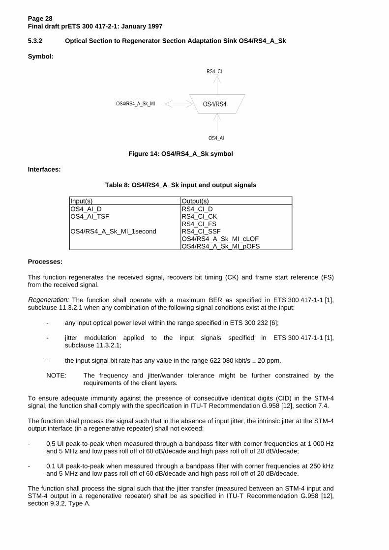
5.3.2 Optical Section to Regenerator Section Adaptation Sink OS4/RS4_A_Sk
Symbol:
OS4/RS4
RS4_CI
OS4_AI
OS4/RS4_A_Sk_MI
Figure 14: OS4/RS4_A_Sk symbol
Interfaces:
Table 8: OS4/RS4_A_Sk input and output signals
Input(s) Output(s)OS4_AI_DOS4_AI_TSF
OS4/RS4_A_Sk_MI_1second
RS4_CI_DRS4_CI_CKRS4_CI_FSRS4_CI_SSFOS4/RS4_A_Sk_MI_cLOFOS4/RS4_A_Sk_MI_pOFS
Processes:
This function regenerates the received signal, recovers bit timing (CK) and frame start reference (FS)from the received signal.
Regeneration: The function shall operate with a maximum BER as specified in ETS 300 417-1-1 [1],subclause 11.3.2.1 when any combination of the following signal conditions exist at the input:
- any input optical power level within the range specified in ETS 300 232 [6];
- jitter modulation applied to the input signals specified in ETS 300 417-1-1 [1],subclause 11.3.2.1;
- the input signal bit rate has any value in the range 622 080 kbit/s ± 20 ppm.
NOTE: The frequency and jitter/wander tolerance might be further constrained by therequirements of the client layers.
To ensure adequate immunity against the presence of consecutive identical digits (CID) in the STM-4signal, the function shall comply with the specification in ITU-T Recommendation G.958 [12], section 7.4.
The function shall process the signal such that in the absence of input jitter, the intrinsic jitter at the STM-4output interface (in a regenerative repeater) shall not exceed:
- 0,5 UI peak-to-peak when measured through a bandpass filter with corner frequencies at 1 000 Hzand 5 MHz and low pass roll off of 60 dB/decade and high pass roll off of 20 dB/decade;
- 0,1 UI peak-to-peak when measured through a bandpass filter with corner frequencies at 250 kHzand 5 MHz and low pass roll off of 60 dB/decade and high pass roll off of 20 dB/decade.
The function shall process the signal such that the jitter transfer (measured between an STM-4 input andSTM-4 output in a regenerative repeater) shall be as specified in ITU-T Recommendation G.958 [12],section 9.3.2, Type A.

Page 29Final draft prETS 300 417-2-1: January 1997
Frame alignment: The frame alignment shall be found by searching for the A1, A2 bytes contained in theSTM-4 signal. The framing pattern searched for may be a subset of the A1 and A2 bytes contained on theSTM-4 signal. The frame signal shall be continuously checked with the presumed frame start position forthe alignment. If in the In-Frame state (IF), the maximum Out-Of-Frame (OOF) detection time shall be625 µs for a random unframed signal. The algorithm used to check the alignment shall be such that,under normal conditions, a 10-3 (Poisson type) error ratio will not cause a false OOF more then once per6 minutes. If in the OOF state, the maximum frame alignment time shall be 250 µs for an error-free signalwith no emulated framing patterns. The algorithm used to recover from the OOF state shall be such , thatthe probability for false frame recovery with a random unframed signal shall be no more than 10-5 per250 µs time interval.
In F ram e(IF)
O ut O f F ram e(O O F )
m ax 5 E rro red F A S s
2 E rro r F ree F A S s
Figure 15: Frame alignment process
The frame start signal (RS4_CI_FS) shall be maintained during the OOF state and only updated uponsuccessful transition form OOF to the IF state.
Defects:
If the OOF anomaly persists for 3 ms, a STM-4 Loss Of Frame defect (dLOF) shall be detected. Toprovide for the case of intermittent OOFs, the integrating timer shall not be reset to zero until an IFcondition persists continuously for 3 ms. The dLOF defect shall be cleared when the IF state persistscontinuously for 3 ms.
Loss Of FrameCleared
(dLOF=false)
Loss Of FrameSet
(dLOF=true)
Out Of Frame for >3ms
In Frame for >3ms
NOTE: Out-Of-Frame integrating timer is not reset to zero until an In-Frame condition persistscontinuously for 3 ms.
Figure 16: Loss of frame process
Consequent Actions:
aAIS ← dLOF or AI_TSF
aSSF ← dLOF or AI_TSF
On declaration of an aAIS the function shall output an all-ONEs AIS signal - complying to the frequencylimits for this interface - within 250 µs; on clearing of aAIS the function shall output normal data within250 µs.
Defect Correlations:
cLOF ← dLOF and (not AI_TSF)
Performance Monitoring:
Any second with at least one OOF event shall be reported as an pOFS (Out of Frame Second).

Page 30Final draft prETS 300 417-2-1: January 1997
6 STM-16 Optical Section Layer Functions
NOTE: Xy.z will be one value out of the set: I16, S16.1, S16.2, L16.1, L16.2, L16.3.
OS16-Xy.z
OS16/RS16
RS16_CI
OS16_AI
OS16_CI
OS16-Xy.z
OS16/RS16
OS16_AI
RS16_CI
OS16_CI
OS16
OS16_CIOS16_CI
Figure 17: STM-16 Optical Section atomic functions
STM-16 Optical Section Layer CP
Characteristic Information OS16_CI of the optical layer CP (figure 18) is a digital, optical signal of definedpower, bit rate, pulse width and wavelength. A range of such characteristic signals for different opticalpower budgets is defined in ETS 300 232 [6].
A1 A1 A2 A21
2
3
4
5
6
7
8
9
1 2 ... 11 48 49 50 ... 96 97 98 112 113 ... 144 145 4320
scrambled STM-16 bytes
...
Figure 18: OS16 characteristic information OS16_CI (optical) and adapted informationOS16_AI (electrical)
STM-16 Optical Section Layer AP
The information passing across the OS16 AP takes the form of a scrambled, digital bitstream (including ablock frame character at 125 µs intervals) with co-directional bit timing (figure 18). Frame characters andthe synchronous, scrambling polynomial are defined in ETS 300 147 [4].
6.1 Optical Section Connection functions
For further study.

Page 31Final draft prETS 300 417-2-1: January 1997
6.2 Optical Section Trail Termination functions
6.2.1 Optical Section Trail Termination Source OS16-Xy.z_TT_So
NOTE 1: Xy.z will be one value out of the set: I16, S16.1, S16.2, L16.1, L16.2, L16.3.
Symbol:
OS16-Xy.z
OS16_AI
OS16_CI
O S 16_T T _S o_M I X: I,S,Ly: 16z: 1,2,3
Figure 19: OS16-Xy.z_TT_So symbol
Interfaces:
Table 9: OS16_TT_So input and output signals
Input(s) Output(s)OS16_AI_D OS16_CI_D
OS16_TT_So_MI_cTDOS16_TT_So_MI_cTF
Processes:
This function forms the optical STM-16 signal for transmission over the optical cable as defined inETS 300 232 [6].
Optical characteristics: The function shall generate an optical STM-16 signal that meets the Xy.zcharacteristics defined in ETS 300 232 [6].
Defects:
dTD, dTF:
NOTE 2: Degraded signal implies that the output although still operational has fallen belowsome threshold of acceptability which requires maintenance intervention. The definitionof the acceptability will in general be specific to a particular design or maintenancephilosophy and is not defined in this ETS. The defects are equipment specific.
Consequent Actions: None.
Defect Correlations:
cTF ← dTF
cTD ← dTD and (not dTF)
Performance Monitoring: None.

Page 32Final draft prETS 300 417-2-1: January 1997
6.2.2 Optical Section Trail Termination Sink OS16-Xy.z_TT_Sk
NOTE 1: Xy.z will be one value out of the set: I16, S16.1, S16.2, L16.1, L16.2, L16.3.
Symbol:
OS16-Xy.z
OS16_AI
OS16_CI
OS16_TT_Sk_MIX: I,S,Ly: 16z: 1,2,3
Figure 20: OS16-Xy.z_TT_Sk symbol
Interfaces:
Table 10: OS16_TT_Sk input and output signals
Input(s) Output(s)OS16_CI_D
OS16_TT_Sk_MI_PortMode
OS16_AI_DOS16_AI_TSFOS16_TT_Sk_MI_cLOS
Processes:
This function recovers the optical STM-16 signal transmitted over the optical cables. The physicalcharacteristics of the interface signal are defined in ETS 300 232 [6].
The function shall convert the received STM-16 signal, normally complying to the Xy.z characteristicsdefined in ETS 300 232 [6], into the internal OS16_AI signal.
Port Mode: The function shall have a port mode as specified by subclause 8.5 of ETS 300 417-1-1 [1].
NOTE 2: The AUTO state of the port mode process is optional.
Defects:
The function shall detect Loss Of Signal defect (dLOS) according the optical STM-16 dLOS specificationin subclause 8.2.1.6 of ETS 300 417-1-1 [1].
Consequent Actions:
aTSF ← dLOS
Defect Correlations:
cLOS ← MON and dLOS
Performance Monitoring: None.

Page 33Final draft prETS 300 417-2-1: January 1997
6.3 Optical Section Adaptation functions
6.3.1 Optical Section to Regenerator Section Adaptation Source OS16/RS16_A_So
Symbol:
OS16/RS16
RS16_CI
OS16_AI
Figure 21: OS16/RS16_A_So symbol
Interfaces:
Table 11: OS16/RS16_A_So input and output signals
Input(s) Output(s)RS16_CI_DRS16_CI_CK
OS16_AI_D
Processes:
The function shall not add any jitter.
NOTE: Jitter at the NNI is the combination of the jitter generated and transferred via the clientlayers."
Defects: None.
Consequent Actions: None.
Defect Correlations: None.
Performance Monitoring: None.
Page 34Final draft prETS 300 417-2-1: January 1997
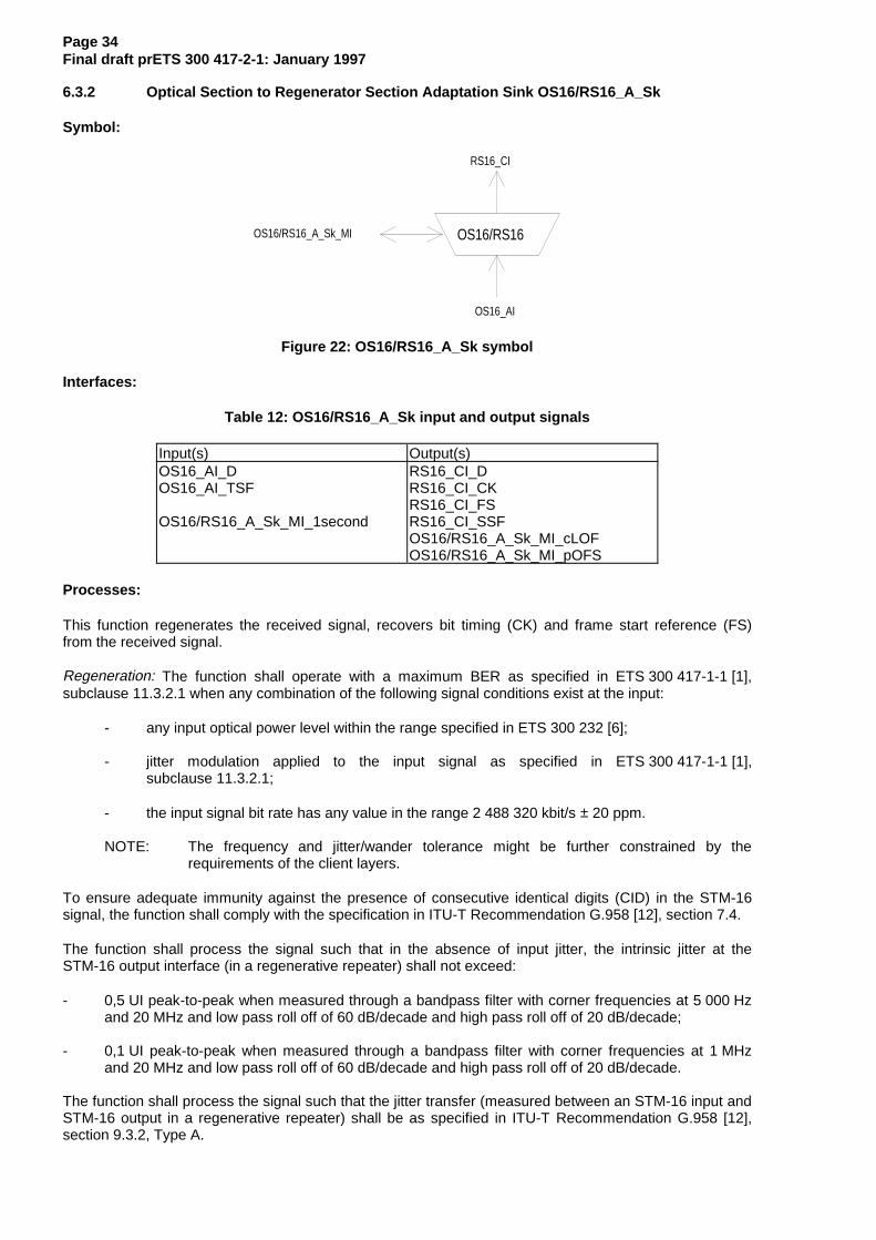
6.3.2 Optical Section to Regenerator Section Adaptation Sink OS16/RS16_A_Sk
Symbol:
OS16/RS16
RS16_CI
OS16_AI
OS16/RS16_A_Sk_MI
Figure 22: OS16/RS16_A_Sk symbol
Interfaces:
Table 12: OS16/RS16_A_Sk input and output signals
Input(s) Output(s)OS16_AI_DOS16_AI_TSF
OS16/RS16_A_Sk_MI_1second
RS16_CI_DRS16_CI_CKRS16_CI_FSRS16_CI_SSFOS16/RS16_A_Sk_MI_cLOFOS16/RS16_A_Sk_MI_pOFS
Processes:
This function regenerates the received signal, recovers bit timing (CK) and frame start reference (FS)from the received signal.
Regeneration: The function shall operate with a maximum BER as specified in ETS 300 417-1-1 [1],subclause 11.3.2.1 when any combination of the following signal conditions exist at the input:
- any input optical power level within the range specified in ETS 300 232 [6];
- jitter modulation applied to the input signal as specified in ETS 300 417-1-1 [1],subclause 11.3.2.1;
- the input signal bit rate has any value in the range 2 488 320 kbit/s ± 20 ppm.
NOTE: The frequency and jitter/wander tolerance might be further constrained by therequirements of the client layers.
To ensure adequate immunity against the presence of consecutive identical digits (CID) in the STM-16signal, the function shall comply with the specification in ITU-T Recommendation G.958 [12], section 7.4.
The function shall process the signal such that in the absence of input jitter, the intrinsic jitter at theSTM-16 output interface (in a regenerative repeater) shall not exceed:
- 0,5 UI peak-to-peak when measured through a bandpass filter with corner frequencies at 5 000 Hzand 20 MHz and low pass roll off of 60 dB/decade and high pass roll off of 20 dB/decade;
- 0,1 UI peak-to-peak when measured through a bandpass filter with corner frequencies at 1 MHzand 20 MHz and low pass roll off of 60 dB/decade and high pass roll off of 20 dB/decade.
The function shall process the signal such that the jitter transfer (measured between an STM-16 input andSTM-16 output in a regenerative repeater) shall be as specified in ITU-T Recommendation G.958 [12],section 9.3.2, Type A.

Page 35Final draft prETS 300 417-2-1: January 1997
Frame alignment: The frame alignment shall be found by searching for the A1, A2 bytes contained in theSTM-16 signal. The framing pattern searched for may be a subset of the A1 and A2 bytes contained onthe STM-16 signal. The frame signal shall be continuously checked with the presumed frame start positionfor the alignment. If in the In-Frame state (IF), the maximum Out-Of-Frame (OOF) detection time shall be625 µs for a random unframed signal. The algorithm used to check the alignment shall be such that,under normal conditions, a 10-3 (Poisson type) error ratio will not cause a false OOF more then once per6 minutes. If in the OOF state, the maximum frame alignment time shall be 250 µs for an error-free signalwith no emulated framing patterns. The algorithm used to recover from the OOF state shall be such , thatthe probability for false frame recovery with a random unframed signal shall be no more than 10-5 per250 µs time interval.
In F ram e(IF)
O ut O f F ram e(O O F )
m ax 5 E rro red F A S s
2 E rro r F ree F A S s
Figure 23: Frame alignment process
The frame start signal (RS16_CI_FS) shall be maintained during the OOF state and only updated uponsuccessful transition form OOF to the IF state.
Defects:
If the OOF anomaly persists for 3 ms, a STM-16 Loss Of Frame defect (dLOF) shall be detected. Toprovide for the case of intermittent OOFs, the integrating timer shall not be reset to zero until an IFcondition persists continuously for 3 ms. The dLOF defect shall be cleared when the IF state persistscontinuously for 3 ms.
Loss Of FrameCleared
(dLOF=false)
Loss Of FrameSet
(dLOF=true)
Out Of Frame for >3ms
In Frame for >3ms
NOTE: Out-Of-Frame integrating timer is not reset to zero until an In-Frame condition persistscontinuously for 3 ms.
Figure 24: Loss of frame process
Consequent Actions:
aAIS ← dLOF or AI_TSF
aSSF ← dLOF or AI_TSF
On declaration of an aAIS the function shall output an all-ONEs (AIS) signal - complying to the frequencylimits for this interface - within 250 µs; on clearing of aAIS the function shall output normal data within250 µs.
Defect Correlations:
cLOF ← dLOF and (not AI_TSF)
Performance Monitoring:
Any second with at least one OOF event shall be reported as an pOFS (Out of Frame Second).

Page 36Final draft prETS 300 417-2-1: January 1997
7 STM-64 Optical Section Layer Functions
For further study.
8 STM-1 Electrical Section Layer Functions
ES1
ES1/RS1
RS1_CI
ES1_AI
ES1_CI
ES1
ES1/RS1
ES1_AI
RS1_CI
ES1_CI
ES1_CI ES1_CI
ES1
Figure 25: STM-1 Electrical Section atomic functions
STM-1 Electrical Section layer CP
The Characteristic Information ES1_CI of the intra-station electrical STM-1 layer CP (figure 26) is a digital,CMI encoded, electrical signal of defined amplitude, bit rate and pulse shape as defined inETS 300 166 [5].
NOTE: Characteristic information for a STM-1 UNI is for further study.
1 2 3 4 5 6 7 8 9 10 .... 2701 A1 A1 A1 A2 A2 A22345 scrambled STM-1 bytes
6789
Figure 26: ES1 characteristic and adaptation information ES1_CI and ES1_AI
STM-1 Electrical Section layer AP
The information passing across the STM-1 ES AP takes the form of a scrambled, digital bitstream(including a block frame character at 125 µs intervals) with co-directional bit timing (figure 26). Framecharacters and the synchronous, scrambling polynomial is defined in ETS 300 147 [4].
8.1 STM-1 Electrical Section Connection function ES1_C
For further study.

Page 37Final draft prETS 300 417-2-1: January 1997
8.2 STM-1 Electrical Section Trail Termination functions
8.2.1 STM-1 Electrical Section Trail Termination Source ES1_TT_So
Symbol:
ES1
ES1_AI
ES1_CI
Figure 27: ES1_TT_So symbol
Interfaces:
Table 13: ES1_TT_So input and output signals
Input(s) Output(s)ES1_AI_D ES1_CI_D
Processes:
This function generates the STM-1 electrical Intra-station Section Layer signal as specified byETS 300 166 [5].
Pulse shape: The function shall meet the requirement specified by ETS 300 166 [5].
Peak to peak voltage: The function shall meet the requirement specified by ETS 300 166 [5].
Rise time: The function shall meet the requirement specified by ETS 300 166 [5].
Pair(s) in each direction: The function shall meet the requirement specified by ETS 300 166 [5].
Output return loss: The function shall meet the requirement specified by ETS 300 166 [5].
Defects: None.
Consequent Actions: None.
Defect Correlations: None.
Performance Monitoring: None.

Page 38Final draft prETS 300 417-2-1: January 1997
8.2.2 STM-1 Electrical Section Trail Termination Sink ES1_TT_Sk
Symbol:
ES1
ES1_AI
ES1_CI
ES1_TT_Sk_MI
Figure 28: ES1-S1.1_TT_Sk symbol
Interfaces:
Table 14: ES1_TT_Sk input and output signals
Input(s) Output(s)ES1_CI_D
ES1_TT_Sk_MI_PortMode
ES1_AI_DES1_AI_TSFES1_TT_Sk_MI_cLOS
Processes:
This function recovers the electrical STM-1 Intra-station Section Layer signal as defined inETS 300 166 [5].
Input return loss: The function shall meet the requirement specified by ETS 300 166 [5].
Port Mode: The function shall have a port mode as specified by subclause 8.5 of ETS 300 417-1-1 [1].
NOTE: The AUTO state of the port mode process is optional.
Defects:
The function shall detect Loss Of Signal defect (dLOS) according the electrical STM-1 dLOS specificationin subclause 8.2.1.6 of ETS 300 417-1-1 [1].
Consequent Actions:
aTSF ← dLOS
Defect Correlations:
cLOS ← MON and dLOS
Performance Monitoring: None.

Page 39Final draft prETS 300 417-2-1: January 1997
8.3 STM-1 Electrical Section Adaptation functions
8.3.1 STM-1 Electrical Section to Regenerator Section Adaptation Source ES1/RS1_A_So
Symbol:
ES1/RS1
RS1_CI
ES1_AI
Figure 29: ES1/RS1_A_So symbol
Interfaces:
Table 15: ES1/RS1_A_So input and output signals
Input(s) Output(s)RS1_CI_DRS1_CI_CK
ES1_AI_D
Processes:
This function provides CMI encoding of the STM-1 signal.
CMI encoder: The function shall perform CMI encoding of the data specified by ETS 300 166 [5].
The CMI encoding process in the function shall process the signal such that in the absence of input jitterat the synchronization interface, the intrinsic jitter at the SMT-1 output interface as measured over a60 seconds interval shall not exceed:
- 0,5 UI peak-peak when measured through a band-pass filter with corner frequencies at 500 Hz and1,3 MHz and low pass roll off of 60 dB/decade and high pass roll off of 20 dB/decade;
- 0,075 UI peak-peak when measured through a band-pass filter with corner frequencies at 65 kHzand 1,3 MHz and low pass roll off of 60 dB/decade and high pass roll off of 20 dB/decade.
Consequent Actions: None.
Defect Correlations: None.
Performance Monitoring: None.
Page 40Final draft prETS 300 417-2-1: January 1997
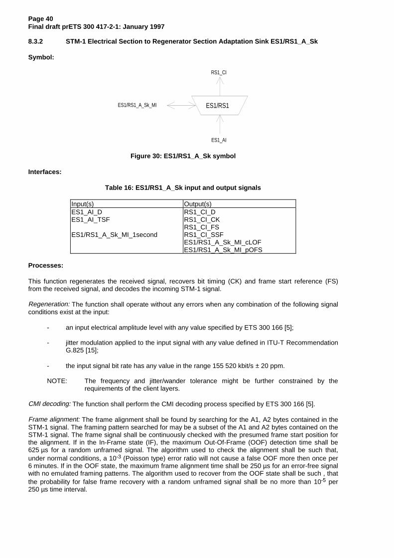
8.3.2 STM-1 Electrical Section to Regenerator Section Adaptation Sink ES1/RS1_A_Sk
Symbol:
ES1/RS1
RS1_CI
ES1_AI
ES1/RS1_A_Sk_MI
Figure 30: ES1/RS1_A_Sk symbol
Interfaces:
Table 16: ES1/RS1_A_Sk input and output signals
Input(s) Output(s)ES1_AI_DES1_AI_TSF
ES1/RS1_A_Sk_MI_1second
RS1_CI_DRS1_CI_CKRS1_CI_FSRS1_CI_SSFES1/RS1_A_Sk_MI_cLOFES1/RS1_A_Sk_MI_pOFS
Processes:
This function regenerates the received signal, recovers bit timing (CK) and frame start reference (FS)from the received signal, and decodes the incoming STM-1 signal.
Regeneration: The function shall operate without any errors when any combination of the following signalconditions exist at the input:
- an input electrical amplitude level with any value specified by ETS 300 166 [5];
- jitter modulation applied to the input signal with any value defined in ITU-T RecommendationG.825 [15];
- the input signal bit rate has any value in the range 155 520 kbit/s ± 20 ppm.
NOTE: The frequency and jitter/wander tolerance might be further constrained by therequirements of the client layers.
CMI decoding: The function shall perform the CMI decoding process specified by ETS 300 166 [5].
Frame alignment: The frame alignment shall be found by searching for the A1, A2 bytes contained in theSTM-1 signal. The framing pattern searched for may be a subset of the A1 and A2 bytes contained on theSTM-1 signal. The frame signal shall be continuously checked with the presumed frame start position forthe alignment. If in the In-Frame state (IF), the maximum Out-Of-Frame (OOF) detection time shall be625 µs for a random unframed signal. The algorithm used to check the alignment shall be such that,under normal conditions, a 10-3 (Poisson type) error ratio will not cause a false OOF more then once per6 minutes. If in the OOF state, the maximum frame alignment time shall be 250 µs for an error-free signalwith no emulated framing patterns. The algorithm used to recover from the OOF state shall be such , thatthe probability for false frame recovery with a random unframed signal shall be no more than 10-5 per250 µs time interval.

Page 41Final draft prETS 300 417-2-1: January 1997
In F ram e(IF)
O ut O f F ram e(O O F )
m ax 5 E rro red F A S s
2 E rro r F ree F A S s
Figure 31: Frame alignment process
The frame start signal (RS1_CI_FS) shall be maintained during the OOF state and only updated uponsuccessful transition form OOF to the IF state.
Defects:
If the OOF anomaly persists for 3 ms, a STM-1 Loss Of Frame defect (dLOF) shall be detected. Toprovide for the case of intermittent OOFs, the integrating timer shall not be reset to zero until an IFcondition persists continuously for 3 ms. The dLOF defect shall be cleared when the IF state persistscontinuously for 3 ms.
Loss Of FrameCleared
(dLOF=false)
Loss Of FrameSet
(dLOF=true)
Out Of Frame for >3ms
In Frame for >3ms
NOTE: Out-Of-Frame integrating timer is not reset to zero until an In-Frame condition persistscontinuously for 3 ms.
Figure 32: Loss of frame process
Consequent Actions:
aAIS ← dLOF or AI_TSF
aSSF ← dLOF or AI_TSF
On declaration of aAIS the function shall output an all-ONEs (AIS) signal - complying to the frequencylimits for this interface - within 250 µs; on clearing of aAIS the function shall output normal data within250 µs.
Defect Correlations:
cLOF ← dLOF and (not AI_TSF)
Performance Monitoring:
Any second with at least one OOF event shall be reported as an pOFS (Out of Frame Second).

Page 42Final draft prETS 300 417-2-1: January 1997
9 E4 Section Layer Functions
E4
E4/P4x
E4
E4/P4x
P4x_CI P4x_CI
E4_CI E4_CI
E4/P4e E4/P4s
P4e_CI P4s_CI
E4/P4e
P4e_CI
E4/P4s
P4s_CI
E4_CI E4_CI
E4
Figure 33: E4 Section atomic functions
E4 layer CP
The Characteristic Information E4_CI on the intra-station electrical layer CP is a digital, CMI encoded,electrical signal of defined amplitude, bit rate and pulse shape as defined in ETS 300 166 [5].
E4 layer AP
The information passing across the E4/P4x AP is a plesiochronous 139 264 kbit/s signal of non-specifiedcontent with co-directional bit timing.
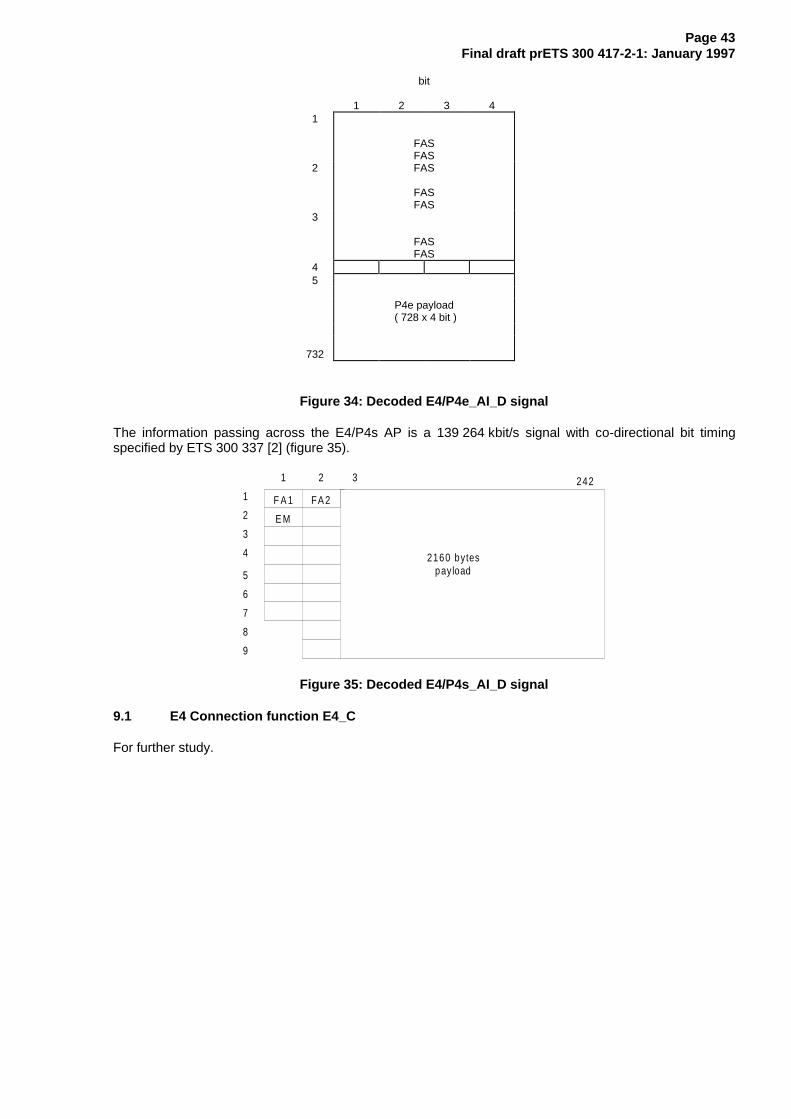
The information passing across the E4/P4e AP is a 139 264 kbit/s signal with co-directional bit timingspecified by ITU-T Recommendation G.751 [7]. It contains four 34 368 kbit/s tributary signals (figure 34).
Figure 33 shows that more than one adaptation function exists in this E4 layer that can be connected toone E4 access point. For the case of the adaptation source functions, only one of these adaptation sourcefunctions is allowed to be activated. For this activated source, access to the access point by otheradaptation source functions shall be denied. In contradiction with the source direction, adaptation sinkfunctions may be activated all together. This may cause faults (e.g. cLOF) to be detected and reported. Toprevent this an adaptation sink function can be deactivated.
NOTE: If one adaptation function only is connected to the AP, it will be activated. If one ormore other functions are connected to the same AP, one out of the set of functions willbe active.
Page 43Final draft prETS 300 417-2-1: January 1997
bit
1 2 3 41
FASFAS
2 FAS
FASFAS
3
FASFAS
45
P4e payload ( 728 x 4 bit )
732
Figure 34: Decoded E4/P4e_AI_D signal
The information passing across the E4/P4s AP is a 139 264 kbit/s signal with co-directional bit timingspecified by ETS 300 337 [2] (figure 35).
F A 1 F A 2
2160 bytespayload
1
2
3
4
5
6
7
8
9
1 2 3 242
E M
Figure 35: Decoded E4/P4s_AI_D signal
9.1 E4 Connection function E4_C
For further study.

Page 44Final draft prETS 300 417-2-1: January 1997
9.2 E4 Trail Termination functions
9.2.1 E4 Trail Termination Source E4_TT_So
Symbol:
E4
E4_AI
E4_CI
Figure 36: E4_TT_So symbol
Interfaces:
Table 17: E4_TT_So input and output signals
Input(s) Output(s)E4_AI_D E4_CI_D
Processes:
This function generates the electrical Intra-station Section Layer signal E4 specified by ETS 300 166 [5].
Pulse shape: The function shall meet the requirement specified by ETS 300 166 [5].
Peak to Peak Voltage: The function shall meet the requirement specified by ETS 300 166 [5].
Rise time: The function shall meet the requirement specified by ETS 300 166 [5].
Pair(s) in each direction: The function shall meet the requirement specified by ETS 300 166 [5].
Output return loss: The function shall meet the requirement specified by ETS 300 166 [5].
Defects: None.
Consequent Actions: None.
Defect Correlations: None.
Performance Monitoring: None.

Page 45Final draft prETS 300 417-2-1: January 1997
9.2.2 E4 Trail Termination Sink E4_TT_Sk
Symbol:
E4
E4_AI
E4_CI
E4_TT_Sk_MI
Figure 37: E4_TT_Sk symbol
Interfaces:
Table 18: E4_TT_Sk input and output signals
Input(s) Output(s)E4_CI_D
E4_TT_Sk_MI_PortMode
E4_AI_DE4_AI_TSFE4_TT_Sk_MI_cLOS
Processes:
This function recovers the electrical Intra-station Section Layer signal E4 specified by ETS 300 166 [5].
Input return loss: The function shall meet the requirement specified by ETS 300 166 [5].
Port Mode: The function shall have a port mode as specified by subclause 8.5 of ETS 300 417 1-1 [1].
NOTE: The AUTO state of the port mode process is optional.
Defects:
The function shall detect Loss Of Signal defect (dLOS) according the 139 264 kbit/s dLOS specification insubclause 8.2.1.6 of ETS 300 417-1-1 [1].
Consequent Actions:
aTSF ← dLOS
Defect Correlations:
cLOS ← MON and dLOS
Performance Monitoring: None.

Page 46Final draft prETS 300 417-2-1: January 1997
9.3 E4 Adaptation functions
9.3.1 E4 to P4x Adaptation Source E4/P4x_A_So
Symbol:
E4/P4x
P4x_CI
E4_AI
E4/P4x_A_So_MI
Figure 38: E4/P4x_A_So symbol
Interfaces:
Table 19: E4/P4x_A_So input and output signals
Input(s) Output(s)P4x_CI_DP4x_CI_CKE4/P4x_A_So_MI_Active
E4_AI_D
Processes:
This function provides the CMI encoding of the 139 264 kbit/s information stream as defined inETS 300 166 [5].
CMI encoder: The function shall perform CMI encoding of the data specified by ETS 300 166 [5].
The function shall not add any jitter.
NOTE: Jitter at the NNI is the combination of the jitter generated and transferred via the clientlayers.
Activation: The function shall access the access point when it is activated (MI_Active is true). Otherwise, itshall not access the access point.
Defects: None.
Consequent Actions: None.
Defect Correlations: None.
Performance Monitoring: None.

Page 47Final draft prETS 300 417-2-1: January 1997
9.3.2 E4 to P4x Adaptation Sink E4/P4x_A_Sk
Symbol:
E4/P4x
P4x_CI
E4_AI
E4/P4x_A_Sk_MI
Figure 39: E4/P4x_A_Sk symbol
Interfaces:
Table 20: E4/P4x_A_Sk input and output signals
Input(s) Output(s)E4_AI_DE4_AI_TSFE4/P4x_A_Sk_MI_Active
P4x_CI_DP4x_CI_CKP4x_CI_SSF
Processes:
This function regenerates the received signal, recovers bit timing (CK) from the received signal, anddecodes the incoming electrical 139 264 kbit/s E4 signal.
Regeneration: The function shall operate without any errors when any combination of the following signalconditions exist at the input:
- an input electrical amplitude level with any value in the range specified by ETS 300 166 [5];
- jitter modulation applied to the input signal with any value defined in ITU-T RecommendationG.823 [9];
- the input signal bit rate has any value in the range 139 264 kbit/s ± 15 ppm.
NOTE: The frequency and jitter/wander tolerance might be further constrained by therequirements of the client layers.
CMI decoding: The function shall perform the CMI decoding process specified by ETS 300 166 [5].
Activation: The function shall perform the operation specified above when it is activated (MI_Active istrue). Otherwise, it shall transmit the all-ONEs signal at its output (CI_D) and not report its status via themanagement point.
Defects: None.
Consequent Actions:
aSSF ← AI_TSF
aAIS ← AI_TSF
On declaration of aAIS the function shall output an all-ONEs (AIS) signal - complying to the frequencylimits for this interface - within 250 µs; on clearing of aAIS the function shall output normal data within250 µs.

Page 48Final draft prETS 300 417-2-1: January 1997
Defect Correlations: None.
Performance Monitoring: None.

Page 49Final draft prETS 300 417-2-1: January 1997
9.3.3 E4 to P4e Adaptation Source E4/P4e_A_So
Symbol:
E4/P4e
P4e_CI
E4_AI
E4/P4e_A_So_MI
Figure 40: E4/P4e_A_So symbol
Interfaces:
Table 21: E4/P4e_So input and output signals
Input(s) Output(s)P4e_CI_DP4e_CI_CKE4/P4e_A_So_MI_Active
E4_AI_D
Processes:
This function performs CMI encoding of the 139 264 kbit/s signal.
CMI encoder: The function shall perform CMI encoding of the data as specified in ETS 300 166 [5].
The function shall not add any jitter.
NOTE: Jitter at the NNI is the combination of the jitter generated and transferred via the clientlayers.
Activation: The function shall access the access point when it is activated (MI_Active is true). Otherwise, itshall not access the access point.
Defects: None.
Consequent Actions: None.
Defect Correlations: None.
Performance Monitoring: None.

Page 50Final draft prETS 300 417-2-1: January 1997
9.3.4 E4 to P4e Adaptation Sink E4/P4e_A_Sk
Symbol:
E4/P4e
P4e_CI
E4_AI
E4/P4e_A_Sk_MI
Figure 41: E4/P4e_A_Sk symbol
Interfaces:
Table 22: E4/P4e_Sk input and output signals
Input(s) Output(s)E4_AI_D
E4_AI_TSFE4/P4e_A_Sk_MI_AIS_ReportedE4/P4e_A_Sk_MI_Active
P4e_CI_DP4e_CI_CKP4e_CI_FSP4e_CI_SSFE4/P4e_A_Sk_MI_cLOFE4/P4e_A_Sk_MI_cAIS
Processes:
The function regenerates the received signal, recovers bit timing (CK) and frame start reference (FS) fromthe received signal, and decodes the incoming electrical 139 264 kbit/s E4 signal.
Regeneration: The function shall operate without any errors when any combination of the following signalconditions exist at the input:
- an input electrical amplitude level with any value in the range specified by ETS 300 166 [5];
- jitter modulation applied to the input signal with any value defined in ITU-T RecommendationG.823 [9];
- the input signal bit rate has any value in the range 139 264 kbit/s ± 15 ppm.
NOTE: The frequency and jitter/wander tolerance might be further constrained by therequirements of the client layers.
CMI decoding: The function shall perform the CMI decoding process specified by ETS 300 166 [5].
Frame alignment: The function shall perform the frame alignment of the 139 264 kbit/s signal to recoverthe frame start signal FS. Loss of frame alignment shall be assumed to have taken place when fourconsecutive frame alignment signals have been incorrectly received in their predicted positions.
When frame alignment is assumed to be lost, the frame alignment device shall decide that such alignmenthas effectively been recovered when it detects the presence of three consecutive frame alignment signals.
The frame alignment device having detected the appearance of a single correct frame alignment signal,shall begin a new search for the frame alignment signal when it detects the absence of the framealignment signal in one of the two following frames.
Page 51Final draft prETS 300 417-2-1: January 1997
Activation: The function shall perform the operation specified above when it is activated (MI_Active istrue). Otherwise, it shall transmit the all-ONEs signal at its output (CI_D) and not report its status via themanagement point.
Defects:
The function shall detect a loss of frame defect (dLOF) when four consecutive frame alignment signalshave been incorrectly received in their predicted positions. When frame alignment is lost, the dLOF defectshall be cleared when three consecutive frame alignment signals are detected.
The function shall detect an AIS defect (dAIS) according the specification in subclause 8.2.1.7 ofETS 300 417-1-1 [1], with X = 5, Y = 2 928, Z = 6.
Consequent Actions:
aAIS ← dAIS or dLOF or AI_TSF
aSSF ← dAIS or dLOF or AI_TSF
On declaration of aAIS the function shall output an all-ONEs (AIS) signal - complying to the frequencylimits for this interface - within 250 µs; on clearing of aAIS the function shall output normal data within250 µs.
Defect Correlations:
cAIS ← dAIS and (not AI_TSF) and AIS_Reported
cLOF ← dLOF and (not dAIS) and (not AI_TSF)
Performance Monitoring: None.

Page 52Final draft prETS 300 417-2-1: January 1997
9.3.5 E4 to P4s Adaptation Source E4/P4s_A_So
Symbol:
E4/P4s
P4s_CI
E4_AI
E4/P4s_A_So_MI
Figure 42: E4/P4s_A_So symbol
Interfaces:
Table 23: E4/P4s_So input and output signals
Input(s) Output(s)P4s_CI_DP4s_CI_CKE4/P4s_A_So_MI_Active
E4_AI_D
Processes:
This function provides CMI encoding of the 139 264 kbit/s P4s signal.
CMI encoder: The function shall perform CMI encoding of the data as specified in ETS 300 166 [5].
The function shall not add any jitter.
NOTE: Jitter at the NNI is the combination of the jitter generated and transferred via the clientlayers.
Activation: The function shall access the access point when it is activated (MI_Active is true). Otherwise, itshall not access the access point.
Defects: None.
Consequent Actions: None.
Defect Correlations: None.
Performance Monitoring: None.

Page 53Final draft prETS 300 417-2-1: January 1997
9.3.6 E4 to P4s Adaptation Sink E4/P4s_A_Sk
Symbol:
E4/P4s
P4s_CI
E4_AI
E4/P4s_A_Sk_MI
Figure 43: E4/P4s_A_Sk symbol
Interfaces:
Table 24: E4/P4s_Sk input and output signals
Input(s) Output(s)E4_AI_D
E4_AI_TSFE4/P4s_A_Sk_MI_AIS_ReportedE4/P4s_A_Sk_MI_ActiveE4/P4s_A_Sk_MI_1second
P4s_CI_DP4s_CI_CKP4s_CI_FSP4s_CI_SSFE4/P4s_A_Sk_MI_cLOFE4/P4s_A_Sk_MI_cAISE4/P4s_A_Sk_MI_pOFS
Processes:
The function regenerates the received signal, recovers bit timing (CK), decodes the incoming electrical139 264 kbit/s E4 signal, and recovers frame start reference (FS).
Regeneration: The function shall operate without any errors when any combination of the following signalconditions exist at the input:
- an input electrical amplitude level with any value in the range specified by ETS 300 166 [5];
- jitter modulation applied to the input signal with any value defined in ITU-T RecommendationG.823 [9];
- the input signal bit rate has any value in the range 139 264 kbit/s ± 15 ppm.
NOTE 1: The frequency and jitter/wander tolerance might be further constrained by therequirements of the client layers.
CMI decoding: The function shall perform the CMI decoding process specified by ETS 300 166 [5].
Frame alignment: The function shall perform the frame alignment of the 139 264 kbit/s signal to recoverthe frame start signal FS. The frame alignment shall be found by searching for the A1, A2 bytes containedin the 140 Mbit/s signal. The frame signal shall be continuously checked with the presumed frame startposition for the alignment.
Frame alignment is deemed to have been lost (entering Out Of Frame (OOF) state) when either:
- four consecutive FAS are detected in error (i.e. ≥ 1 error in each FAS);
- 986 or more frames with one or more BIP8 violations are detected in a block of 1 000 frames.
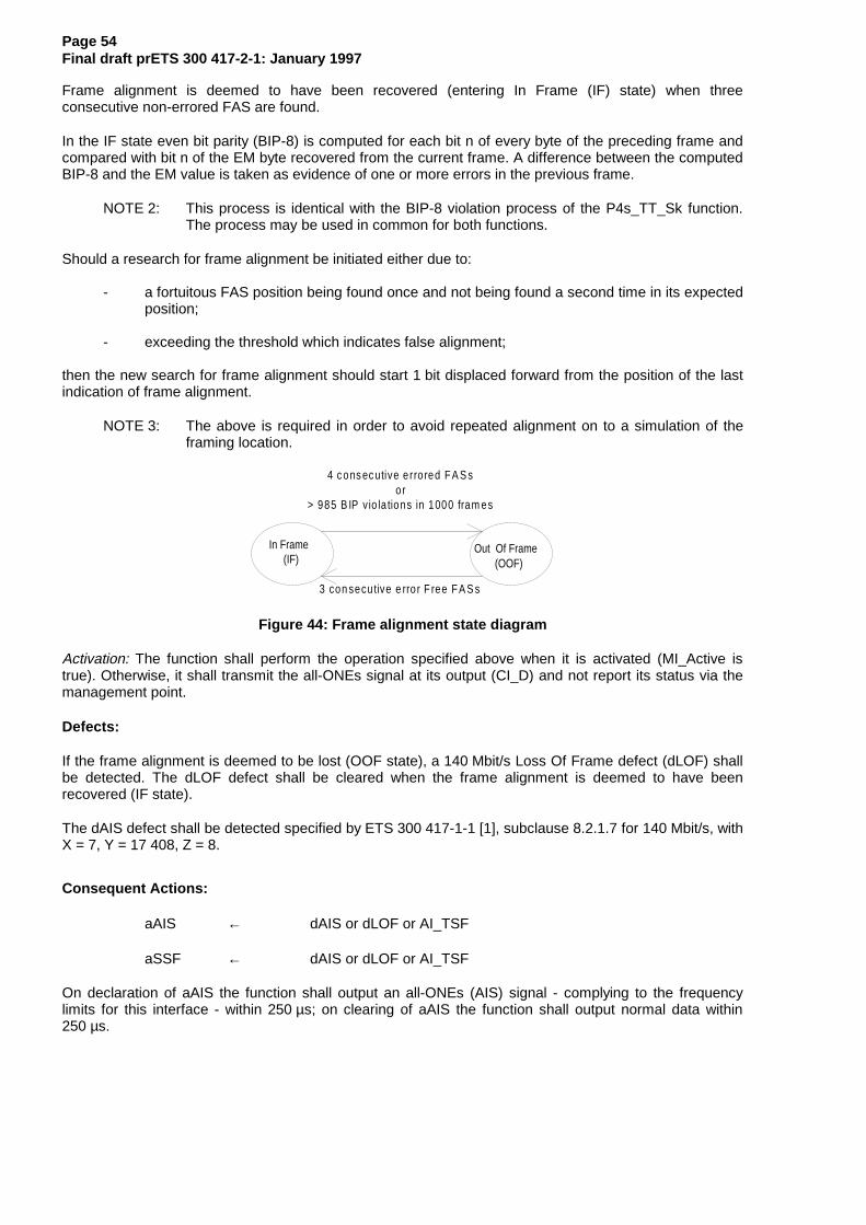
Page 54Final draft prETS 300 417-2-1: January 1997
Frame alignment is deemed to have been recovered (entering In Frame (IF) state) when threeconsecutive non-errored FAS are found.
In the IF state even bit parity (BIP-8) is computed for each bit n of every byte of the preceding frame andcompared with bit n of the EM byte recovered from the current frame. A difference between the computedBIP-8 and the EM value is taken as evidence of one or more errors in the previous frame.
NOTE 2: This process is identical with the BIP-8 violation process of the P4s_TT_Sk function.The process may be used in common for both functions.
Should a research for frame alignment be initiated either due to:
- a fortuitous FAS position being found once and not being found a second time in its expectedposition;
- exceeding the threshold which indicates false alignment;
then the new search for frame alignment should start 1 bit displaced forward from the position of the lastindication of frame alignment.
NOTE 3: The above is required in order to avoid repeated alignment on to a simulation of theframing location.
In Frame(IF)
Out Of Frame(OOF)
4 c ons ec utive e rro red F A S sor
> 985 B IP v io la tions in 1000 fram es
3 con secu tive e rro r F ree F A S s
Figure 44: Frame alignment state diagram
Activation: The function shall perform the operation specified above when it is activated (MI_Active istrue). Otherwise, it shall transmit the all-ONEs signal at its output (CI_D) and not report its status via themanagement point.
Defects:
If the frame alignment is deemed to be lost (OOF state), a 140 Mbit/s Loss Of Frame defect (dLOF) shallbe detected. The dLOF defect shall be cleared when the frame alignment is deemed to have beenrecovered (IF state).
The dAIS defect shall be detected specified by ETS 300 417-1-1 [1], subclause 8.2.1.7 for 140 Mbit/s, withX = 7, Y = 17 408, Z = 8.
Consequent Actions:
aAIS ← dAIS or dLOF or AI_TSF
aSSF ← dAIS or dLOF or AI_TSF
On declaration of aAIS the function shall output an all-ONEs (AIS) signal - complying to the frequencylimits for this interface - within 250 µs; on clearing of aAIS the function shall output normal data within250 µs.

Page 55Final draft prETS 300 417-2-1: January 1997
Defect Correlations:
cAIS ← dAIS and (not AI_TSF) and AIS_Reported
cLOF ← dLOF and (not dAIS) and (not AI_TSF)
Performance Monitoring: None.

Page 56Final draft prETS 300 417-2-1: January 1997
10 E31 Section Layer Functions
E31
E31/P31x
E31
E31/P31x
P31x_CI P31x_CI
E31_CI E31_CI
E31/P31e E31/P31s
P31e_CI P31s_CI
E31/P31e
P31e_CI
E31/P31s
P31s_CI
E31
E31_AI E31_AI
Figure 45: E31 Section atomic functions
E31 layer CP
The Characteristic Information E31_CI of the intra-station electrical layer CP is a digital, electrical signal ofdefined amplitude, bit rate and pulse shape specified by ETS 300 166 [5].
E31 layer AP
The information passing across the E31/P31x AP is a 34 368 kbit/s signal of non-specified content withco-directional bit timing.
The information passing across the E31/P31e AP is a 34 368 kbit/s signal with co-directional bit timingspecified by ITU-T Recommendation G.751 [7]. It contains four 8 448 kbit/s tributary signals (figure 46).
Figure 45 shows that more than one adaptation function exists in this E31 layer that can be connected toone E31 access point. For the case of the adaptation source functions, only one of these adaptationsource functions is allowed to be activated. For this activated source, access to the access point by otheradaptation source functions shall be denied. In contradiction with the source direction, adaptation sinkfunctions may be activated all together. This may cause faults (e.g. cLOF) to be detected and reported. Toprevent this an adaptation sink function can be deactivated.
NOTE: If one adaptation function only is connected to the AP, it will be activated. If one ormore other functions are connected to the same AP, one out of the set of functions willbe active.

Page 57Final draft prETS 300 417-2-1: January 1997
bits1 2 3 4
12 FAS
FASFASFAS
3
4
P31 payload ( 381 x 4 bit )
384
Figure 46: Decoded E31/P31e_AI_D signal
The information passing across the E31/P31s AP is a 34 368 kbit/s signal with co-directional bit timingspecified by ETS 300 337 [2] (figure 47).
F A 1 F A 2
530 bytespayload
1
2
3
4
5
6
7
8
9
1 2 3 60
E M
Figure 47: Decoded E31/P31s_AI_D signal
10.1 E31 Connection function E31_C
For further study.

Page 58Final draft prETS 300 417-2-1: January 1997
10.2 E31 Trail Termination functions
10.2.1 E31 Trail Termination Source E31_TT_So
Symbol:
E31
E31_AI
E31_CI
Figure 48: E31_TT_So symbol
Interfaces:
Table 25: E31_TT_So input and output signals
Input(s) Output(s)E31_AI_D E31_CI_D
Processes:
This function generates the electrical Intra-station Section Layer signal E31 specified by ETS 300 166 [5].
Pulse shape: The function shall meet the requirement specified by ETS 300 166 [5].
Nominal Peak to Peak Voltage of a mark (pulse): The function shall meet the requirement specified byETS 300 166 [5].
Peak voltage of a space (no pulse): The function shall meet the requirement specified by ETS 300 166 [5].
Nominal pulse width: The function shall meet the requirement specified by ETS 300 166 [5].
Ratio of the amplitudes of positive and negative pulses at the centre of the pulse interval: The functionshall meet the requirement specified by ETS 300 166 [5].
Ratio of widths of positive and negative pulses at the nominal half amplitude: The function shall meet therequirement specified by ETS 300 166 [5].
Pair(s) in each direction: The function shall meet the requirement specified by ETS 300 166 [5].
Output return loss: The function shall meet the requirement specified by ETS 300 166 [5].
Defects: None.
Consequent Actions: None.
Defect Correlations: None.
Performance Monitoring: None.
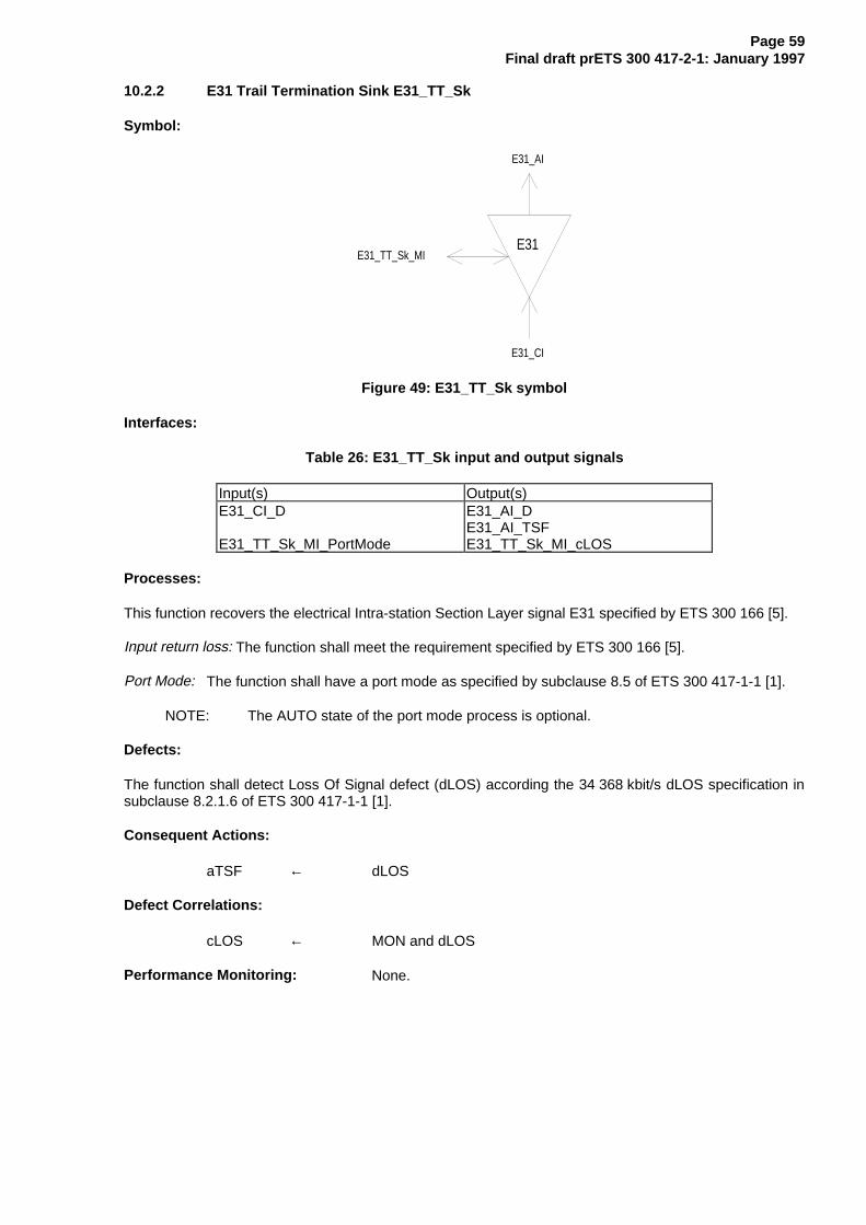
Page 59Final draft prETS 300 417-2-1: January 1997
10.2.2 E31 Trail Termination Sink E31_TT_Sk
Symbol:
E31
E31_AI
E31_CI
E31_TT_Sk_MI
Figure 49: E31_TT_Sk symbol
Interfaces:
Table 26: E31_TT_Sk input and output signals
Input(s) Output(s)E31_CI_D
E31_TT_Sk_MI_PortMode
E31_AI_DE31_AI_TSFE31_TT_Sk_MI_cLOS
Processes:
This function recovers the electrical Intra-station Section Layer signal E31 specified by ETS 300 166 [5].
Input return loss: The function shall meet the requirement specified by ETS 300 166 [5].
Port Mode: The function shall have a port mode as specified by subclause 8.5 of ETS 300 417-1-1 [1].
NOTE: The AUTO state of the port mode process is optional.
Defects:
The function shall detect Loss Of Signal defect (dLOS) according the 34 368 kbit/s dLOS specification insubclause 8.2.1.6 of ETS 300 417-1-1 [1].
Consequent Actions:
aTSF ← dLOS
Defect Correlations:
cLOS ← MON and dLOS
Performance Monitoring: None.

Page 60Final draft prETS 300 417-2-1: January 1997
10.3 E31 Adaptation functions
10.3.1 E31 to P31x Adaptation Source E31/P31x_A_So
Symbol:
E31/P31x
P31x_CI
E31_AI
E31/P31x_A_So_MI
Figure 50: E31/P31x_A_So symbol
Interfaces:
Table 27: E31/P31x_A_So input and output signals
Input(s) Output(s)P31x_CI_DP31x_CI_CKE31/P31x_A_So_MI_Active
E31_AI_D
Processes:
This function provides the HDB3 encoding of the 34 368 kbit/s information stream specified byETS 300 166 [5].
HDB3 encoder: The function shall perform HDB3 encoding of the data as specified in ETS 300 166 [5].
The function shall not add any jitter.
NOTE: Jitter at the NNI is the combination of the jitter generated and transferred via the clientlayers.
Activation: The function shall access the access point when it is activated (MI_Active is true). Otherwise, itshall not access the access point.
Defects: None.
Consequent Actions: None.
Defect Correlations: None.
Performance Monitoring: None.

Page 61Final draft prETS 300 417-2-1: January 1997
10.3.2 E31 to P31x Adaptation Sink E31/P31x_A_Sk
Symbol:
E31/P31x
P31x_CI
E31_AI
E31/P31x_A_Sk_MI
Figure 51: E31/P31x_A_Sk symbol
Interfaces:
Table 28: E31/P31x_A_Sk input and output signals
Input(s) Output(s)E31_AI_DE31_AI_TSFE31/P31x_A_Sk_MI_Active
P31x_CI_DP31x_CI_CKP31x_CI_SSF
Processes:
This function regenerates the received signal, recovers bit timing (CK) from the received signal, anddecodes the incoming electrical 34 368 kbit/s E31 signal.
Regeneration: The function shall operate without any errors when any combination of the following signalconditions exist at the input:
- an input electrical amplitude level with any value in the range specified by ETS 300 166 [5];
- jitter modulation applied to the input signal with any value defined in ITU-T RecommendationG.823 [9];
- the input signal bit rate has any value in the range 34 368 kbit/s ± 20 ppm;
- the input signal has an interfering signal specified by ETS 300 166 [5].
NOTE: The frequency and jitter/wander tolerance might be further constrained by therequirements of the client layers.
HDB3 decoding: The function shall perform the HDB3 decoding process specified by ETS 300 166 [5].
Activation: The function shall perform the operation specified above when it is activated (MI_Active istrue). Otherwise, it shall transmit the all-ONEs signal at its output (CI_D) and not report its status via themanagement point.
Defects: None.
Consequent Actions:
aSSF ← AI_TSF
aAIS ← AI_TSF

Page 62Final draft prETS 300 417-2-1: January 1997
On declaration of aAIS the function shall output an all-ONEs (AIS) signal - complying to the frequencylimits for this interface - within 250 µs; on clearing of aAIS the function shall output normal data within250 µs.
Defect Correlations: None.
Performance Monitoring: None.

Page 63Final draft prETS 300 417-2-1: January 1997
10.3.3 E31 to P31e Adaptation Source E31/P31e_A_So
Symbol:
E31/P31e
P31e_CI
E31_AI
E31/P31e_A_So_MI
Figure 52: E31/P31e_A_So symbol
Interfaces:
Table 29: E31/P31e_A_So input and output signals
Input(s) Output(s)P31e_CI_DP31e_CI_CKE31/P31e_A_So_MI_Active
E31_AI_D
Processes:
This function performs HDB3 encoding of the 34 368 kbit/s signal.
HDB3 encoder: The function shall perform HDB3 encoding of the data as specified in ETS 300 166 [5].
The function shall not add any jitter.
NOTE: Jitter at the NNI is the combination of the jitter generated and transferred via the clientlayers.
Activation: The function shall access the access point when it is activated (MI_Active is true). Otherwise, itshall not access the access point.
Defects: None.
Consequent Actions: None.
Defect Correlations: None.
Performance Monitoring: None.

Page 64Final draft prETS 300 417-2-1: January 1997
10.3.4 E31 to P31e Adaptation Sink E31/P31e_A_Sk
Symbol:
E31/P31e
P31e_CI
E31_AI
E31/P31e_A_Sk_MI
Figure 53: E31/P31e_A_Sk symbol
Interfaces:
Table 30: E31/P31e_A_Sk input and output signals
Input(s) Output(s)E31_AI_D
E31_AI_TSFE31/P31e_A_Sk_MI_AIS_ReportedE31/P31e_A_Sk_MI_Active
P31e_CI_DP31e_CI_CKP31e_CI_FSP31e_CI_SSFE31/P31e_A_Sk_MI_cLOFE31/P31e_A_Sk_MI_cAIS
Processes:
The function regenerates the received signal, recovers bit timing (CK) and frame start reference (FS) fromthe received signal, and decodes the incoming electrical 34 368 kbit/s E31 signal.
Regeneration: The function shall operate without any errors when any combination of the following signalconditions exist at the input:
- an input electrical amplitude level with any value in the range specified by ETS 300 166 [5];
- jitter modulation applied to the input signal with any value defined in ITU-T RecommendationG.823 [9];
- the input signal bit rate has any value in the range 34 368 kbit/s ± 20 ppm;
- the input signal has an interfering signal specified by ETS 300 166 [5].
NOTE: The frequency and jitter/wander tolerance might be further constrained by therequirements of the client layers.
HDB3 decoding: The function shall perform the HDB3 decoding process specified by ETS 300 166 [5].
Frame alignment: The function shall perform the frame alignment of the 34 368 kbit/s signal to recover theframe start signal FS. Loss of frame alignment shall be assumed to have taken place when fourconsecutive frame alignment signals have been incorrectly received in their predicted positions.
When frame alignment is assumed to be lost, the frame alignment device shall decide that such alignmenthas effectively been recovered when it detects the presence of three consecutive frame alignment signals.
The frame alignment device having detected the appearance of a single correct frame alignment signal,shall begin a new search for the frame alignment signal when it detects the absence of the framealignment signal in one of the two following frames.

Page 65Final draft prETS 300 417-2-1: January 1997
Activation: The function shall perform the operation specified above when it is activated (MI_Active istrue). Otherwise, it shall transmit the all-ONEs signal at its output (CI_D) and not report its status via themanagement point.
Defects:
The function shall detect a loss of frame defect (dLOF) when four consecutive frame alignment signalshave been incorrectly received in their predicted positions. When frame alignment is lost, the dLOF defectshall be cleared when three consecutive frame alignment signals are detected.
The function shall detect an AIS defect (dAIS) according the specification in subclause 8.2.1.7 ofETS 300 417-1-1 [1], with X = 4, Y = 1 536, Z = 5.
Consequent Actions:
aAIS ← dAIS or dLOF or AI_TSF
aSSF ← dAIS or dLOF or AI_TSF
On declaration of aAIS the function shall output an all-ONEs (AIS) signal - complying to the frequencylimits for this interface - within 250 µs; on clearing of aAIS the function shall output normal data within250 µs.
Defect Correlations:
cAIS ← dAIS and (not AI_TSF) and AIS_Reported
cLOF ← dLOF and (not dAIS) and (not AI_TSF)
Performance Monitoring: None.

Page 66Final draft prETS 300 417-2-1: January 1997
10.3.5 E31 to P31s Adaptation Source E31/P31s_A_So
Symbol:
E31/P31s
P31s_CI
E31_AI
E31/P31s_A_So_MI
Figure 54: E31/P31s_A_So symbol
Interfaces:
Table 31: E31/P31s_A_So input and output signals
Input(s) Output(s)P31s_CI_DP31s_CI_CKE31/P31s_A_So_MI_Active
E31_AI_D
Processes:
This function provides HDB3 encoding of the 34 368 kbit/s P31s signal.
HDB3 encoder: The function shall perform HDB3 encoding of the data as specified in ETS 300 166 [5].
The function shall not add any jitter.
NOTE: Jitter at the NNI is the combination of the jitter generated and transferred via the clientlayers.
Activation: The function shall access the access point when it is activated (MI_Active is true). Otherwise, itshall not access the access point.
Defects: None.
Consequent Actions: None.
Defect Correlations: None.
Performance Monitoring: None.

Page 67Final draft prETS 300 417-2-1: January 1997
10.3.6 E31 to P31s Adaptation Sink E31/P31s_A_Sk
Symbol:
E31/P31s
P31s_CI
E31_AI
E31/P31s_A_Sk_MI
Figure 55: E31/P31s_A_Sk symbol
Interfaces:
Table 32: E31/P31s_A_Sk input and output signals
Input(s) Output(s)E31_AI_D
E31_AI_TSFE31/P31s_A_Sk_MI_AIS_ReportedE31/P31s_A_Sk_MI_ActiveE31/P31s_A_SK_MI_1second
P31s_CI_DP31s_CI_CKP31s_CI_FSP31s_CI_SSFE31/P31s_A_Sk_MI_cLOFE31/P31s_A_Sk_MI_cAISE31/P31s_A_Sk_MI_pOFS
Processes:
The function regenerates the received signal, recovers bit timing (CK), decodes the incoming electrical34 368 kbit/s E31 signal, and recovers frame start reference (FS). It supplies the recovered timing signalto the synchronization distribution layer. It can be activated/deactivated when multiple adaptation functiontypes are connected to the access point.
Regeneration: The function shall operate without any errors when any combination of the following signalconditions exist at the input:
- an input electrical amplitude level with any value in the range specified by ETS 300 166 [5];
- jitter modulation applied to the input signal with any value defined in ITU-T RecommendationG.823 [9];
- the input signal bit rate has any value in the range 34 368 kbit/s ± 20 ppm;
- the input signal has an interfering signal specified by ETS 300 166 [5].
NOTE 1: The frequency and jitter/wander tolerance might be further constrained by therequirements of the client layers.
HDB3 decoding: The function shall perform the HDB3 decoding process specified by ETS 300 166 [5].
Frame alignment: The function shall perform the frame alignment of the 34 368 kbit/s signal to recover theframe start signal FS. The frame alignment shall be found by searching for the A1, A2 bytes contained inthe 34 Mbit/s signal. The frame signal shall be continuously checked with the presumed frame startposition for the alignment.
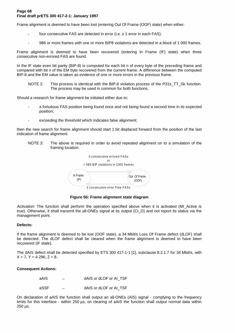
Page 68Final draft prETS 300 417-2-1: January 1997
Frame alignment is deemed to have been lost (entering Out Of Frame (OOF) state) when either:
- four consecutive FAS are detected in error (i.e. ≥ 1 error in each FAS);
- 986 or more frames with one or more BIP8 violations are detected in a block of 1 000 frames.
Frame alignment is deemed to have been recovered (entering In Frame (IF) state) when threeconsecutive non-errored FAS are found.
In the IF state even bit parity (BIP-8) is computed for each bit n of every byte of the preceding frame andcompared with bit n of the EM byte recovered from the current frame. A difference between the computedBIP-8 and the EM value is taken as evidence of one or more errors in the previous frame.
NOTE 2: This process is identical with the BIP-8 violation process of the P31s_TT_Sk function.The process may be used in common for both functions.
Should a research for frame alignment be initiated either due to:
- a fortuitous FAS position being found once and not being found a second time in its expectedposition;
- exceeding the threshold which indicates false alignment;
then the new search for frame alignment should start 1 bit displaced forward from the position of the lastindication of frame alignment.
NOTE 3: The above is required in order to avoid repeated alignment on to a simulation of theframing location.
In Frame(IF)
Out Of Frame(OOF)
4 c ons ec utive e rro red F A S sor
> 985 B IP v io la tions in 1000 fram es
3 con secu tive e rro r F ree F A S s
Figure 56: Frame alignment state diagram
Activation: The function shall perform the operation specified above when it is activated (MI_Active istrue). Otherwise, it shall transmit the all-ONEs signal at its output (CI_D) and not report its status via themanagement point.
Defects:
If the frame alignment is deemed to be lost (OOF state), a 34 Mbit/s Loss Of Frame defect (dLOF) shallbe detected. The dLOF defect shall be cleared when the frame alignment is deemed to have beenrecovered (IF state).
The dAIS defect shall be detected specified by ETS 300 417-1-1 [1], subclause 8.2.1.7 for 34 Mbit/s, withX = 7, Y = 4 296, Z = 8.
Consequent Actions:
aAIS ← dAIS or dLOF or AI_TSF
aSSF ← dAIS or dLOF or AI_TSF
On declaration of aAIS the function shall output an all-ONEs (AIS) signal - complying to the frequencylimits for this interface - within 250 µs; on clearing of aAIS the function shall output normal data within250 µs.

Page 69Final draft prETS 300 417-2-1: January 1997
Defect Correlations:
cAIS ← dAIS and (not AI_TSF) and AIS_Reported
cLOF ← dLOF and (not dAIS) and (not AI_TSF)
Performance Monitoring: None.

Page 70Final draft prETS 300 417-2-1: January 1997
11 E22 Section Layer Functions
E22
E22/P22x
E22
E22/P22x
P22x_CI P22x_CI
E22_CI E22_CI
E22/P22e
P22e_CI
E22/P22e
P22e_CI
E22
E22_AI E22_AI
Figure 57: E22 Section atomic functions
E22 layer CP
The Characteristic Information E22_CI of the intra-station electrical CP is a digital, electrical signal ofdefined amplitude, bit rate and pulse shape specified by ETS 300 166 [5].
E22 layer AP
The information passing across the E22/P22x AP is a 8 448 kbit/s signal with co-directional bit timing.
The information passing across the E22/P22e AP is a 8 448 kbit/s signal with co-directional bit timing. Itcontains four 2 048 kbit/s tributary signals (figure 58).
Figure 57 shows that more than one adaptation function exists in this E22 layer that can be connected toone E22 access point. For the case of the adaptation source functions, only one of these adaptationsource functions is allowed to be activated. For this activated source, access to the access point by otheradaptation source functions shall be denied. In contradiction with the source direction, adaptation sinkfunctions may be activated all together. This may cause faults (e.g. cLOF) to be detected and reported. Toprevent this an adaptation sink function can be deactivated.
NOTE: If one adaptation function only is connected to the AP, it will be activated. If one ormore other functions are connected to the same AP, one out of the set of functions willbe active.
bits1 2 3 4
12 FAS
FASFAS
34
P22 payload ( 209 x 4 bit )
7212
Figure 58: Decoded E22/P22e_AI_D signal

Page 71Final draft prETS 300 417-2-1: January 1997
11.1 E22 Connection function E22_C
For further study.

Page 72Final draft prETS 300 417-2-1: January 1997
11.2 E22 Trail Termination functions
11.2.1 E22 Trail Termination Source E22_TT_So
Symbol:
E22
E22_AI
E22_CI
Figure 59: E22_TT_So symbol
Interfaces:
Table 33: E22_TT_So input and output signals
Input(s) Output(s)E22_AI_D E22_CI_D
Processes:
This function generates the electrical Intra-station Section Layer signal E22 specified by ETS 300 166 [5].
Pulse shape: The function shall meet the requirement specified by ETS 300 166 [5].
Nominal Peak Voltage of a mark (pulse): The function shall meet the requirement specified byETS 300 166 [5].
Peak voltage of a space (no pulse): The function shall meet the requirement specified by ETS 300 166 [5].
Nominal pulse width: The function shall meet the requirement specified by ETS 300 166 [5].
Ratio of the amplitudes of positive and negative pulses at the centre of the pulse interval: The functionshall meet the requirement specified by ETS 300 166 [5].
Ratio of widths of positive and negative pulses at the nominal half amplitude: The function shall meet therequirement specified by ETS 300 166 [5].
Pair(s) in each direction: The function shall meet the requirement specified by ETS 300 166 [5].
Output return loss: The function shall meet the requirement specified by ETS 300 166 [5].
Defects: None.
Consequent Actions: None.
Defect Correlations: None.
Performance Monitoring: None.

Page 73Final draft prETS 300 417-2-1: January 1997
11.2.2 E22 Trail Termination Sink E22_TT_Sk
Symbol:
E22
E22_AI
E22_CI
E22_TT_Sk_MI
Figure 60: E22_TT_Sk symbol
Interfaces:
Table 34: E22_TT_Sk input and output signals
Input(s) Output(s)E22_CI_D
E22_TT_Sk_MI_PortMode
E22_AI_DE22_AI_TSFE22_TT_Sk_MI_cLOS
Processes:
This function recovers the electrical Intra-station Section Layer signal E22 specified by ETS 300 166 [5].
Input return loss: The function shall meet the requirement specified by ETS 300 166 [5].
Port Mode: The function shall have a port mode as specified by subclause 8.5 of ETS 300 417-1-1 [1].
NOTE: The AUTO state of the port mode process is optional.
Defects:
The function shall detect Loss Of Signal defect (dLOS) according the 8 448 kbit/s dLOS specification insubclause 8.2.1.6 of ETS 300 417-1-1 [1].
Consequent Actions:
aTSF ← dLOS
Defect Correlations:
cLOS ← MON and dLOS
Performance Monitoring: None.
Page 74Final draft prETS 300 417-2-1: January 1997
11.3 E22 Adaptation functions
11.3.1 E22 to P22x Adaptation Source E22/P22x_A_So
Symbol:
E22/P22x
P22x_CI
E22_AI
E22/P22x_A_So_MI
Figure 61: E22/P22x_A_So symbol
Interfaces:
Table 35: E22/P22x_A_So input and output signals
Input(s) Output(s)P22x_CI_DP22x_CI_CKE22/P22x_A_So_MI_Active
E22_AI_D
Processes:
This function provides the HDB3 encoding of the 8 448 kbit/s information stream specified byETS 300 166 [5].
HDB3 encoder: The function shall perform HDB3 encoding of the data as specified in ETS 300 166 [5].
The function shall not add any jitter.
NOTE: Jitter at the NNI is the combination of the jitter generated and transferred via the clientlayers.
Activation: The function shall access the access point when it is activated (MI_Active is true). Otherwise, itshall not access the access point.
Defects: None.
Consequent Actions: None.
Defect Correlations: None.
Performance Monitoring: None.
Page 75Final draft prETS 300 417-2-1: January 1997
11.3.2 E22 to P22x Adaptation Sink E22/P22x_A_Sk
Symbol:
E22/P22x
P22x_CI
E22_AI
E22/P22x_A_Sk_MI
Figure 62: E22/P22x_A_Sk symbol
Interfaces:
Table 36: E22/P22x_A_Sk input and output signals
Input(s) Output(s)E22_AI_DE22_AI_TSFE22/P22x_A_Sk_MI_Active
P22x_CI_DP22x_CI_CKP22x_CI_SSF
Processes:
This function regenerates the received signal, recovers bit timing (CK) from the received signal, anddecodes the incoming electrical 8 448 kbit/s E22 signal.
Regeneration: The function shall operate without any errors when any combination of the following signalconditions exist at the input:
- an input electrical amplitude level with any value in the range specified by ETS 300 166 [5];
- jitter modulation applied to the input signal with any value defined in ITU-T RecommendationG.823 [9];
- the input signal bit rate has any value in the range 8 448 kbit/s ± 30 ppm;
- the input signal has an interfering signal specified by ETS 300 166 [5].
NOTE: The frequency and jitter/wander tolerance might be further constrained by therequirements of the client layers.
HDB3 decoding: The function shall perform the HDB3 decoding process specified by ETS 300 166 [5].
Activation: The function shall perform the operation specified above when it is activated (MI_Active istrue). Otherwise, it shall transmit the all-ONEs signal at its output (CI_D) and not report its status via themanagement point.
Defects: None.
Consequent Actions:
aSSF ← AI_TSF
aAIS ← AI_TSF

Page 76Final draft prETS 300 417-2-1: January 1997
On declaration of aAIS the function shall output an all-ONEs (AIS) signal - complying to the frequencylimits for this interface - within 250 µs; on clearing of aAIS the function shall output normal data within250 µs.
Defect Correlations: None.
Performance Monitoring: None.

Page 77Final draft prETS 300 417-2-1: January 1997
11.3.3 E22 to P22e Adaptation Source E22/P22e_A_So
Symbol:
E22/P22e
P22e_CI
E22_AI
E22/P22e_A_So_MI
Figure 63: E22/P22e_A_So symbol
Interfaces:
Table 37: E22/P22e_A_So input and output signals
Input(s) Output(s)P22e_CI_DP22e_CI_CKE22/P22e_A_So_MI_Active
E22_AI_D
Processes:
This function performs HDB3 encoding of the 8 448 kbit/s signal.
HDB3 encoder: The function shall perform HDB3 encoding of the data as specified in ETS 300 166 [5].
The function shall not add any jitter.
NOTE: Jitter at the NNI is the combination of the jitter generated and transferred via the clientlayers.
Activation: The function shall access the access point when it is activated (MI_Active is true). Otherwise, itshall not access the access point.
Defects: None.
Consequent Actions: None.
Defect Correlations: None.
Performance Monitoring: None.

Page 78Final draft prETS 300 417-2-1: January 1997
11.3.4 E22 to P22e Adaptation Sink E22/P22e_A_Sk
Symbol:
E22/P22e
P22e_CI
E22_AI
E22/P22e_A_Sk_MI
Figure 64: E22/P22e_A_Sk symbol
Interfaces:
Table 38: E22/P22e_A_Sk input and output signals
Input(s) Output(s)E22_AI_D
E22_AI_TSFE22/P22e_A_Sk_MI_AIS_ReportedE22/P22e_A_Sk_MI_Active
P22e_CI_DP22e_CI_CKP22e_CI_FSP22e_CI_SSFE22/P22e_A_Sk_MI_cLOFE22/P22e_A_Sk_MI_cAIS
Processes:
The function regenerates the received signal, recovers bit timing (CK) and frame start reference (FS) fromthe received signal, and decodes the incoming electrical 8 448 kbit/s E22 signal. It can beactivated/deactivated when multiple adaptation function types are connected to the access point.
Regeneration: The function shall operate without any errors when any combination of the following signalconditions exist at the input:
- an input electrical amplitude level with any value in the range specified by ETS 300 166 [5];
- jitter modulation applied to the input signal with any value defined in ITU-T RecommendationG.823 [9];
- the input signal bit rate has any value in the range 8 448 kbit/s ± 30 ppm;
- the input signal has an interfering signal specified by ETS 300 166 [5].
HDB3 decoding: The function shall perform the HDB3 decoding process specified by ETS 300 166 [5].
Frame alignment: The function shall perform the frame alignment of the 8 448 kbit/s signal to recover theframe start signal FS. Loss of frame alignment shall be assumed to have taken place when fourconsecutive frame alignment signals have been incorrectly received in their predicted positions.
When frame alignment is assumed to be lost, the frame alignment device shall decide that such alignmenthas effectively been recovered when it detects the presence of three consecutive frame alignment signals.
The frame alignment device having detected the appearance of a single correct frame alignment signal,shall begin a new search for the frame alignment signal when it detects the absence of the framealignment signal in one of the two following frames.

Page 79Final draft prETS 300 417-2-1: January 1997
Activation: The function shall perform the operation specified above when it is activated (MI_Active istrue). Otherwise, it shall transmit the all-ONEs signal at its output (CI_D) and not report its status via themanagement point.
Defects:
The function shall detect a loss of frame defect (dLOF) when four consecutive frame alignment signalshave been incorrectly received in their predicted positions. When frame alignment is lost, the dLOF defectshall be cleared when three consecutive frame alignment signals are detected.
The function shall detect an AIS defect (dAIS) according the specification in subclause 8.2.1.7 ofETS 300 417-1-1 [1], with X = 4, Y = 848, Z = 5.
Consequent Actions:
aAIS ← dAIS or dLOF or AI_TSF
aSSF ← dAIS or dLOF or AI_TSF
On declaration of aAIS the function shall output an all-ONEs (AIS) signal - complying to the frequencylimits for this interface - within 250 µs; on clearing of aAIS the function shall output normal data within250 µs.
Defect Correlations:
cAIS ← dAIS and (not AI_TSF) and AIS_Reported
cLOF ← dLOF and (not dAIS) and (not AI_TSF)
Performance Monitoring: None.

Page 80Final draft prETS 300 417-2-1: January 1997
12 E12 Section Layer Functions
E12-Z
E12/P12x
E12-Z
E12/P12x
P12x_CI P12x_CI
E12_CI E12_CI
E12/P12s
P12s_CI
E12/P12s
P12s_CI
E12
E12_AI E12_AI
Z : 75, 120
Figure 65: E12 Section atomic functions
E12 layer CP
The Characteristic Information E12_CI of the intra-station electrical CP is a digital, electrical signal ofdefined amplitude, bit rate, impedance and pulse shape specified by ETS 300 166 [5].
NOTE: The specification within this ETS is limited to the Network Node Interface (NNI).
E12 layer AP
The information passing across the E12/P12x AP is a 2 048 kbit/s signal with co-directional bit timing.
The information passing across the E12/P12s AP is a 2 048 kbit/s signal with co-directional bit timing witha frame structure specified by ETS 300 167 [3] (figures 66, 67).
Figure 65 shows that more than one adaptation function exists in this E12 layer that can be connected toone E12 access point. For the case of the adaptation source functions, only one of these adaptationsource functions is allowed to be activated. For this activated source, access to the access point by otheradaptation source functions shall be denied. In contradiction with the source direction, adaptation sinkfunctions may be activated all together. This may cause faults (e.g. cLOF) to be detected and reported. Toprevent this an adaptation sink function can be deactivated.
NOTE: If one adaptation function only is connected to the AP, it will be activated. If one ormore other functions are connected to the same AP, one out of the set of functions willbe active.
1 2 3 4 5 6 7 8TS0 FASTS1
2 048 kbit/s payload (31 bytes)TS31TS0 1TS1
2 048 kbit/s payload (31 bytes)TS31
Figure 66: Decoded P12s_CI_D (without CRC-4 multiframe)

Page 81Final draft prETS 300 417-2-1: January 1997
1 2 3 4 5 6 7 8 1 2 3 4 5 6 7 8TS0 C1 FAS TS0 C1 FAS
Frame TS1 Frame TS10 2 048 kbit/s payload (31 bytes) 8 2 048 kbit/s payload (31 bytes)
TS31 TS31
TS0 MFAS bit
1 TS0 MFAS bit
1
Frame TS1 Frame TS11 2 048 kbit/s payload (31 bytes) 9 2 048 kbit/s payload (31 bytes)
TS31 TS31
TS0 C2 FAS TS0 C2 FASFrame TS1 Frame TS1
2 2 048 kbit/s payload (31 bytes) 10 2 048 kbit/s payload (31 bytes)TS31 TS3
1TS0 MFA
S bit1 TS0 MFA
S bit1
Frame TS1 Frame TS13 2 048 kbit/s payload (31 bytes) 11 2 048 kbit/s payload (31 bytes)
TS31 TS31
TS0 C3 FAS TS0 C3 FASFrame TS1 Frame TS1
4 2 048 kbit/s payload (31 bytes) 12 2 048 kbit/s payload (31 bytes)TS31 TS3
1TS0 MFA
S bit1 TS0 E 1
Frame TS1 Frame TS15 2 048 kbit/s payload (31 bytes) 13 2 048 kbit/s payload (31 bytes)
TS31 TS31
TS0 C4 FAS TS0 C4 FASFrame TS1 Frame TS1
6 2 048 kbit/s payload (31 bytes) 14 2 048 kbit/s payload (31 bytes)TS31 TS3
1TS0 MFA
S bit1 TS0 E 1
Frame TS1 Frame TS17 2 048 kbit/s payload (31 bytes) 15 2 048 kbit/s payload (31 bytes)
TS31 TS31
Figure 67: Decoded P12s_CI_D (with CRC-4 multiframe)
12.1 E12 Connection function E12_C
For further study.

Page 82Final draft prETS 300 417-2-1: January 1997
12.2 E12 Trail Termination functions
12.2.1 E12 Trail Termination Source E12-Z_TT_So
NOTE: Z (Ω) will be one value out of the set: 75, 120 (Ω).
Symbol:
E12-Z
E12_AI
E12_CI
Z : 75 , 120
Figure 68: E12-Z_TT_So symbol
Interfaces:
Table 39: E12_TT_So input and output signals
Input(s) Output(s)E12_AI_D E12_CI_D
Processes:
This function generates the electrical Intra-station Section Layer signal E12 specified by ETS 300 166 [5].
Pulse shape: The function shall meet the requirement specified by ETS 300 166 [5].
Nominal Peak Voltage of a mark (pulse): The function shall meet the requirement specified byETS 300 166 [5].
Peak voltage of a space (no pulse): The function shall meet the requirement specified by ETS 300 166 [5].
Nominal pulse width: The function shall meet the requirement specified by ETS 300 166 [5].
Ratio of the amplitudes of positive and negative pulses at the centre of the pulse interval: The functionshall meet the requirement specified by ETS 300 166 [5].
Ratio of widths of positive and negative pulses at the nominal half amplitude: The function shall meet therequirement specified by ETS 300 166 [5].
Pair(s) in each direction: The function shall meet the requirement specified by ETS 300 166 [5].
Output return loss: The function shall meet the requirement specified by ETS 300 166 [5].
Output signal balance: For the case of a 120 Ω interface, the function shall meet the requirement specifiedby ETS 300 166 [5].

Page 83Final draft prETS 300 417-2-1: January 1997
Defects: None.
Consequent Actions: None.
Defect Correlations: None.
Performance Monitoring: None.

Page 84Final draft prETS 300 417-2-1: January 1997
12.2.2 E12 Trail Termination Sink E12-Z_TT_Sk
NOTE: Z (Ω) will be one value out of the set: 75, 120 (Ω).
Symbol:
E12-Z
E12_AI
E12_CI
E12_TT_Sk_MI Z : 75, 120
Figure 69: E12-Z_TT_Sk symbol
Interfaces:
Table 40: E12_TT_Sk input and output signals
Input(s) Output(s)E12_CI_D
E12_TT_Sk_MI_PortMode
E12_AI_DE12_AI_TSFE12_TT_Sk_MI_cLOS
Processes:
This function recovers the electrical Intra-station Section Layer signal E12 specified by ETS 300 166 [5].
Input return loss: The function shall meet the requirement specified by ETS 300 166 [5].
Port Mode: The function shall have a port mode as specified by subclause 8.5 of ETS 300 417-1-1 [1].
NOTE: The AUTO state of the port mode process is optional.
Defects:
The function shall detect Loss Of Signal defect (dLOS) according the 2 048 kbit/s dLOS specification insubclause 8.2.1.6 of ETS 300 417-1-1 [1].
Consequent Actions:
aTSF ← dLOS
Defect Correlations:
cLOS ← MON and dLOS
Performance Monitoring: None.
Page 85Final draft prETS 300 417-2-1: January 1997
12.3 E12 Adaptation functions
12.3.1 E12 to P12x Adaptation Source E12/P12x_A_So
Symbol:
E12/P12x
P12x_CI
E12_AI
E12/P12x_A_So_MI
Figure 70: E12/P12x_A_So symbol
Interfaces:
Table 41: E12/P12x_A_So input and output signals
Input(s) Output(s)P12x_CI_DP12x_CI_CKE12/P12x_A_So_MI_Active
E12_AI_D
Processes:
This function provides the HDB3 encoding of the 2 048 kbit/s information stream specified byETS 300 166 [5].
HDB3 encoder: The function shall perform HDB3 encoding of the data as specified in ETS 300 166 [5].
The function shall not add any jitter.
NOTE: Jitter at the NNI is the combination of the jitter generated and transferred via the clientlayers.
Activation: The function shall access the access point when it is activated (MI_Active is true). Otherwise, itshall not access the access point.
Defects: None.
Consequent Actions: None.
Defect Correlations: None.
Performance Monitoring: None.

Page 86Final draft prETS 300 417-2-1: January 1997
12.3.2 E12 to P12x Adaptation Sink E12/P12x_A_Sk
Symbol:
E12/P12x
P12x_CI
E12_AI
E12/P12x_A_Sk_MI
Figure 71: E12/P12x_A_Sk symbol
Interfaces:
Table 42: E12/P12x_A_Sk input and output signals
Input(s) Output(s)E12_AI_DE12_AI_TSFE12/P12x_A_Sk_MI_Active
P12x_CI_DP12x_CI_CKP12x_CI_SSF
Processes:
This function regenerates the received signal, recovers bit timing (CK) from the received signal, anddecodes the incoming electrical 2 048 kbit/s E12 signal.
Regeneration: The function shall operate without any errors when any combination of the following signalconditions exist at the input:
- an input electrical amplitude level with any value in the range specified by ETS 300 166 [5];
- jitter modulation applied to the input signal with any value defined in ITU-T RecommendationG.823 [9];
- the input signal bit rate has any value in the range 2 048 kbit/s ± 50 ppm;
- the input signal has an interfering signal specified by ETS 300 166 [5];
- for the case of a 120 Ω interface, the input signal has an longitudinal voltage specified byETS 300 166 [5].
NOTE: The frequency and jitter/wander tolerance might be further constrained by therequirements of the client layers.
HDB3 decoding: The function shall perform the HDB3 decoding process specified by ETS 300 166 [5].
Activation: The function shall perform the operation specified above when it is activated (MI_Active istrue). Otherwise, it shall transmit the all-ONEs signal at its output (CI_D) and not report its status via themanagement point.
Defects: None.
Consequent Actions:
aSSF ← AI_TSF
aAIS ← AI_TSF

Page 87Final draft prETS 300 417-2-1: January 1997
On declaration of aAIS the function shall output an all-ONEs (AIS) signal - complying to the frequencylimits for this interface (e.g. 2 048 kHz ± 50 ppm, or nominal frequency) - within 250 µs; on clearing ofaAIS the function shall output normal data within 250 µs.
Defect Correlations: None.
Performance Monitoring: None.
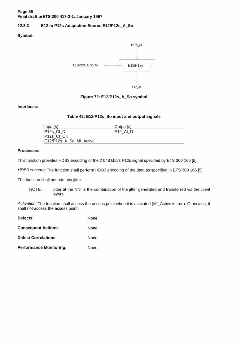
Page 88Final draft prETS 300 417-2-1: January 1997
12.3.3 E12 to P12s Adaptation Source E12/P12s_A_So
Symbol:
E12/P12s
P12s_CI
E12_AI
E12/P12s_A_So_MI
Figure 72: E12/P12s_A_So symbol
Interfaces:
Table 43: E12/P12s_So input and output signals
Input(s) Output(s)P12s_CI_DP12s_CI_CKE12/P12s_A_So_MI_Active
E12_AI_D
Processes:
This function provides HDB3 encoding of the 2 048 kbit/s P12s signal specified by ETS 300 166 [5].
HDB3 encoder: The function shall perform HDB3 encoding of the data as specified in ETS 300 166 [5].
The function shall not add any jitter.
NOTE: Jitter at the NNI is the combination of the jitter generated and transferred via the clientlayers.
Activation: The function shall access the access point when it is activated (MI_Active is true). Otherwise, itshall not access the access point.
Defects: None.
Consequent Actions: None.
Defect Correlations: None.
Performance Monitoring: None.
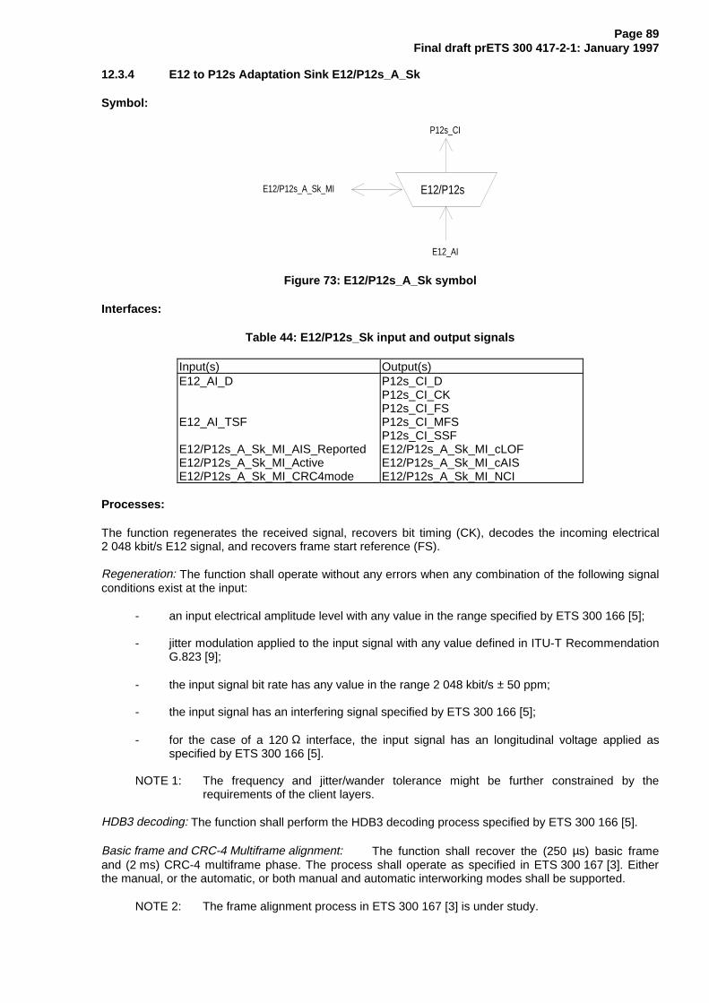
Page 89Final draft prETS 300 417-2-1: January 1997
12.3.4 E12 to P12s Adaptation Sink E12/P12s_A_Sk
Symbol:
E12/P12s
P12s_CI
E12_AI
E12/P12s_A_Sk_MI
Figure 73: E12/P12s_A_Sk symbol
Interfaces:
Table 44: E12/P12s_Sk input and output signals
Input(s) Output(s)E12_AI_D
E12_AI_TSF
E12/P12s_A_Sk_MI_AIS_ReportedE12/P12s_A_Sk_MI_ActiveE12/P12s_A_Sk_MI_CRC4mode
P12s_CI_DP12s_CI_CKP12s_CI_FSP12s_CI_MFSP12s_CI_SSFE12/P12s_A_Sk_MI_cLOFE12/P12s_A_Sk_MI_cAISE12/P12s_A_Sk_MI_NCI
Processes:
The function regenerates the received signal, recovers bit timing (CK), decodes the incoming electrical2 048 kbit/s E12 signal, and recovers frame start reference (FS).
Regeneration: The function shall operate without any errors when any combination of the following signalconditions exist at the input:
- an input electrical amplitude level with any value in the range specified by ETS 300 166 [5];
- jitter modulation applied to the input signal with any value defined in ITU-T RecommendationG.823 [9];
- the input signal bit rate has any value in the range 2 048 kbit/s ± 50 ppm;
- the input signal has an interfering signal specified by ETS 300 166 [5];
- for the case of a 120 Ω interface, the input signal has an longitudinal voltage applied asspecified by ETS 300 166 [5].
NOTE 1: The frequency and jitter/wander tolerance might be further constrained by therequirements of the client layers.
HDB3 decoding: The function shall perform the HDB3 decoding process specified by ETS 300 166 [5].
Basic frame and CRC-4 Multiframe alignment: The function shall recover the (250 µs) basic frameand (2 ms) CRC-4 multiframe phase. The process shall operate as specified in ETS 300 167 [3]. Eitherthe manual, or the automatic, or both manual and automatic interworking modes shall be supported.
NOTE 2: The frame alignment process in ETS 300 167 [3] is under study.
Page 90Final draft prETS 300 417-2-1: January 1997
Activation: The function shall perform the operation specified above when it is activated (MI_Active istrue). Otherwise, it shall transmit the all-ONEs signal at its output (CI_D) and not report its status via themanagement point.
Defects :
The function shall detect dLOF defect as specified by ETS 300 167 [3].
The function shall clear dLOF defect as specified by ETS 300 167 [3].
The function shall report NCI status in the automatic CRC-4 interworking mode as specified byETS 300 167 [3].
The dAIS defect shall be detected specified by ETS 300 417-1-1 [1], subclause 8.2.1.7 for 2 Mbit/s, withX = 2, Y = 512, Z = 3.
Consequent Actions:
aAIS ← dAIS or dLOF or AI_TSF
aSSF ← dAIS or dLOF or AI_TSF
On declaration of aAIS the function shall output an all-ONEs (AIS) signal - complying to the frequencylimits for this interface - within 250 µs; on clearing of aAIS the function shall output normal data within250 µs.
Defect Correlations:
cAIS ← dAIS and (not AI_TSF) and AIS_Reported
cLOF ← dLOF and (not dAIS) and (not AI_TSF)
Performance Monitoring: None.
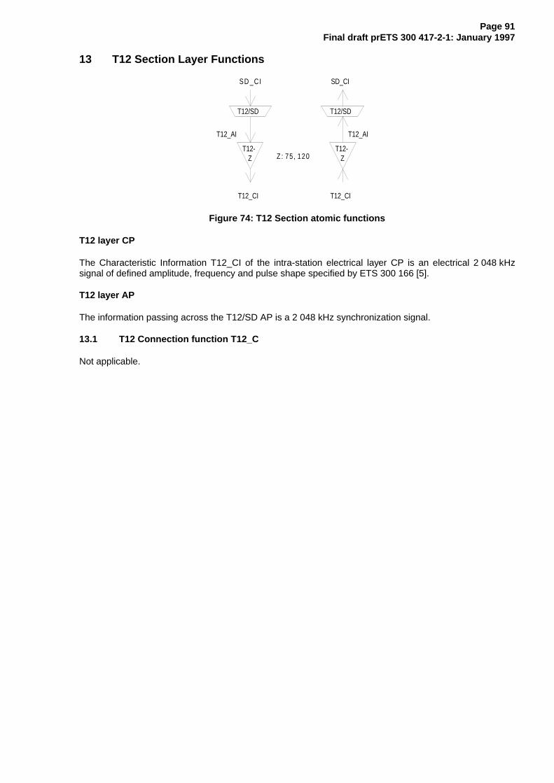
Page 91Final draft prETS 300 417-2-1: January 1997
13 T12 Section Layer Functions
T12-Z
T12/SD
T12-Z
T12/SD
T12_CI T12_CI
Z : 75 , 120
SD_CI
T12_AI T12_AI
SD _CI
Figure 74: T12 Section atomic functions
T12 layer CP
The Characteristic Information T12_CI of the intra-station electrical layer CP is an electrical 2 048 kHzsignal of defined amplitude, frequency and pulse shape specified by ETS 300 166 [5].
T12 layer AP
The information passing across the T12/SD AP is a 2 048 kHz synchronization signal.
13.1 T12 Connection function T12_C
Not applicable.

Page 92Final draft prETS 300 417-2-1: January 1997
13.2 T12 Trail Termination functions
13.2.1 T12 Trail Termination Source T12-Z_TT_So
NOTE 1: Z (Ω) will be one value out of the set: 75, 120 (Ω).
Symbol:
T12-Z
T12_AI
T12_CI
Z : 75 , 120
Figure 75: T12-Z_TT_So symbol
Interfaces:
Table 45: T12_TT_So input and output signals
Input(s) Output(s)T12_AI_CKT12_AI_SQLCH
T12_CI_CK
Processes:
This function generates the electrical 2 048 kHz signal used for transmission of synchronization signals toan external equipment on a plesiochronous intra-station section specified by ETS 300 166 [5].
Pulse shape: The function shall meet the requirement specified by ETS 300 166 [5].
Maximum Peak Voltage: The function shall meet the requirement specified by ETS 300 166 [5].
Minimum peak voltage: The function shall meet the requirement specified by ETS 300 166 [5].
Pair in each direction: The function shall meet the requirement specified by ETS 300 166 [5].
Defects: None.
Consequent Actions:
On activation of T12_AI_SQLCH the function shall shutdown the output within 250 µs; on clearing ofT12_AI_SQLCH the function shall output normal signal within 250 µs.
NOTE 2: For more details refer to ETS 300 417-6-1 [16].
Defect Correlations: None.
Performance Monitoring: None.

Page 93Final draft prETS 300 417-2-1: January 1997
13.2.2 T12 Trail Termination Sink T12-Z_TT_Sk
NOTE 1: Z (Ω) will be one value out of the set: 75, 120 (Ω).
Symbol:
T12-Z
T12_AI
T12_CI
T12_TT_Sk_MIZ : 75 , 120
Figure 76: T12-Z_TT_Sk symbol
Interfaces:
Table 46: T12_TT_Sk input and output signals
Input(s) Output(s)T12_CI_CK
T12_TT_Sk_MI_PortMode
T12_AI_CKT12_AI_TSFT12_TT_Sk_MI_cLOS
Processes:
This function recovers the electrical 2 048 kHz signal used for transmission of synchronization signalsfrom an external equipment on a plesiochronous intra-station section specified by ETS 300 166 [5].
Input return loss: The function shall meet the requirement specified by ETS 300 166 [5].
Port Mode: The function shall have a port mode as specified by subclause 8.5 of ETS 300 417-1-1 [1].
NOTE 2: The AUTO state of the port mode process is optional.
Defects:
The function shall detect 2 048 kHz Loss Of Signal defect (dLOS) as defined for the 2 048 kbit/s dLOSspecification in subclause 8.2.1.6 of ETS 300 417-1-1 [1].
Consequent Actions:
aTSF ← dLOS
Defect Correlations:
cLOS ← MON and dLOS
Performance Monitoring: None.

Page 94Final draft prETS 300 417-2-1: January 1997
13.3 T12 Adaptation functions
13.3.1 T12 to SD Adaptation Source T12/SD_A_So
Refer to ETS 300 417-6-1 [16].
13.3.2 T12 to SD Adaptation Sink T12/SD_A_Sk
Refer to ETS 300 417-6-1 [16].

Page 95Final draft prETS 300 417-2-1: January 1997
14 E0 Section Layer Functions
E 0 E 0
E 0_CI E 0_C I
E 0
E 0_A I E 0_A I
P 0s _C I
E 0/P 0s
P 0s _C I
E 0/P 0s
Figure 77: E0 Section atomic functions
E0 layer CP
The Characteristic Information E0_CI of the intra-station electrical layer CP is a digital, electrical 64 kbit/sco-directional signal set of defined amplitude, bit rate and pulse shape specified by ETS 300 166 [5].
E0 layer AP
The information passing across the E0/P0s AP is a synchronous 64 kbit/s signal with co-directional bittiming and octet identification.
14.1 E0 Connection function E0_C
For further study.
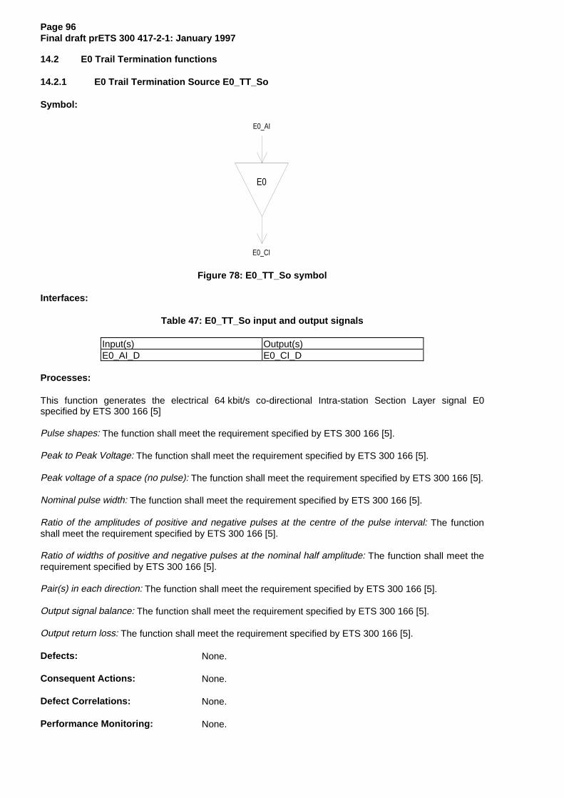
Page 96Final draft prETS 300 417-2-1: January 1997
14.2 E0 Trail Termination functions
14.2.1 E0 Trail Termination Source E0_TT_So
Symbol:
E0
E0_AI
E0_CI
Figure 78: E0_TT_So symbol
Interfaces:
Table 47: E0_TT_So input and output signals
Input(s) Output(s)E0_AI_D E0_CI_D
Processes:
This function generates the electrical 64 kbit/s co-directional Intra-station Section Layer signal E0specified by ETS 300 166 [5]
Pulse shapes: The function shall meet the requirement specified by ETS 300 166 [5].
Peak to Peak Voltage: The function shall meet the requirement specified by ETS 300 166 [5].
Peak voltage of a space (no pulse): The function shall meet the requirement specified by ETS 300 166 [5].
Nominal pulse width: The function shall meet the requirement specified by ETS 300 166 [5].
Ratio of the amplitudes of positive and negative pulses at the centre of the pulse interval: The functionshall meet the requirement specified by ETS 300 166 [5].
Ratio of widths of positive and negative pulses at the nominal half amplitude: The function shall meet therequirement specified by ETS 300 166 [5].
Pair(s) in each direction: The function shall meet the requirement specified by ETS 300 166 [5].
Output signal balance: The function shall meet the requirement specified by ETS 300 166 [5].
Output return loss: The function shall meet the requirement specified by ETS 300 166 [5].
Defects: None.
Consequent Actions: None.
Defect Correlations: None.
Performance Monitoring: None.

Page 97Final draft prETS 300 417-2-1: January 1997
14.2.2 E0 Trail Termination Sink E0_TT_Sk
Symbol:
E0
E0_AI
E0_CI
E0_TT_Sk_MI
Figure 79: E0_TT_Sk symbol
Interfaces:
Table 48: E0_TT_Sk input and output signals
Input(s) Output(s)E0_CI_D
E0_TT_Sk_MI_PortMode
E0_AI_DE0_AI_TSFE0_TT_Sk_MI_cLOS
Processes:
This function recovers the electrical Intra-station Section Layer signal E0 specified by ETS 300 166 [5].
Input return loss: The function shall meet the requirement specified by ETS 300 166 [5].
Impedance towards ground: The function shall meet the requirement specified by ETS 300 166 [5].
Port Mode: The function shall have a port mode as specified by subclause 8.5 of ETS 300 417-1-1 [1].
NOTE 1: The AUTO state of the port mode process is optional.
Defects:
The function shall detect a Loss Of Signal defect (dLOS) according the 64 kbit/s dLOS specification insubclause 8.2.1.6 of ETS 300 417-1-1 [1].
NOTE 2: An E0 interface used for OW or User Channel does not need to be monitored for lossof signal.
Consequent Actions:
aTSF ← dLOS
Defect Correlations:
cLOS ← MON and dLOS
Performance Monitoring: None.
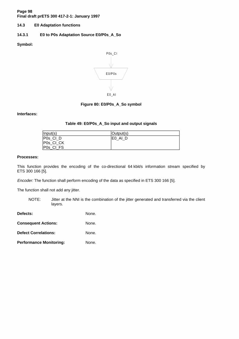
Page 98Final draft prETS 300 417-2-1: January 1997
14.3 E0 Adaptation functions
14.3.1 E0 to P0s Adaptation Source E0/P0s_A_So
Symbol:
E 0/P 0s
P 0s _C I
E 0_A I
Figure 80: E0/P0s_A_So symbol
Interfaces:
Table 49: E0/P0s_A_So input and output signals
Input(s) Output(s)P0s_CI_DP0s_CI_CKP0s_CI_FS
E0_AI_D
Processes:
This function provides the encoding of the co-directional 64 kbit/s information stream specified byETS 300 166 [5].
Encoder: The function shall perform encoding of the data as specified in ETS 300 166 [5].
The function shall not add any jitter.
NOTE: Jitter at the NNI is the combination of the jitter generated and transferred via the clientlayers.
Defects: None.
Consequent Actions: None.
Defect Correlations: None.
Performance Monitoring: None.

Page 99Final draft prETS 300 417-2-1: January 1997
14.3.2 E0 to P0s Adaptation Sink E0/P0s_A_Sk
Symbol:
E 0/P 0s
P 0s_C I
E 0_A I
Figure 81: E0/P0s_A_Sk symbol
Interfaces:
Table 50: E0/P0s_A_Sk input and output signals
Input(s) Output(s)E0_AI_DE0_AI_TSF
P0s_CI_DP0s_CI_CKP0s_CI_FSP0s_CI_SSF
Processes:
This function regenerates the received signal, recovers bit timing (CK) and octet timing from the receivedsignal, and decodes the incoming electrical co-directional 64 kbit/s E0 signal.
Regeneration: The function shall operate without any errors when any combination of the following signalconditions exist at the input:
- an input electrical amplitude level with any value in the range specified by ETS 300 166 [5];
- jitter modulation applied to the input signal with any value defined in ITU-T RecommendationG.823 [9];
- the input signal bit rate has any value in the range 64 kbit/s ± 100 ppm;
- the input signal has an interfering signal specified by ETS 300 166 [5];
- the input signal has an longitudinal voltage applied as specified by ETS 300 166 [5].
NOTE 1: The frequency and jitter/wander tolerance might be further constrained by therequirements of the client layers.
Decoding and octet alignment: The function shall perform the decoding and octet alignment processes asspecified in ETS 300 166 [5] for 64 kbit/s co-directional interfaces.
Defects: None.
NOTE 2: The addition of a Loss of Octet Timing defect (dLOT) is for further study.

Page 100Final draft prETS 300 417-2-1: January 1997
Consequent Actions:
aAIS ← AI_TSF
aSSF ← AI_TSF
On declaration of aAIS the function shall output an all-ONEs (AIS) signal - complying to the frequencylimits for this interface (e.g. 64 kHz ± 100 ppm, or nominal frequency) - within 250 µs; on clearing of aAISthe function shall output normal data within 250 µs.
Defect Correlations: None.
Performance Monitoring: None.

Page 101Final draft prETS 300 417-2-1: January 1997
Annex A (informative): E32 Section Layer Functions
E32
E32/P32x
E32
E32/P32x
P32x_CI P32x_CI
E32_CI E32_CI
E32
E32_AI E32_AI
Figure A.1: E32 Section atomic functions
E32 layer CP
The Characteristic Information E32_CI of the intra-station electrical layer CP is a digital, electrical signal ofdefined amplitude, bit rate and pulse shape specified by ANSI T1.102 [13].
NOTE: The pulse shape defined in ANSI T1.102 [13] is for the signal at the digital distributionframe, not at the connector of the equipment.
E32 layer AP
The information passing across the E32/P32x AP is a 44 736 kbit/s signal with co-directional bit timing.
A.1 E32 Connection function E32_C
For further study.

Page 102Final draft prETS 300 417-2-1: January 1997
A.2 E32 Trail Termination functions
A.2.1 E32 Trail Termination Source E32_TT_So
Symbol:
E32
E32_AI
E32_CI
Figure A.2: E32_TT_So symbol
Interfaces:
Table A.1: E32_TT_So input and output signals
Input(s) Output(s)E32_AI_D E32_CI_D
Processes:
This function generates the electrical Intra-station Section Layer signal E32 specified by ANSI T1.102 [13].
The function shall meet the medium, pulse amplitude, pulse shape, power level, pulse imbalance and DCpower requirements specified by ANSI T1.102 [13].
Defects: None.
Consequent Actions: None.
Defect Correlations: None.
Performance Monitoring: None.

Page 103Final draft prETS 300 417-2-1: January 1997
A.2.2 E32 Trail Termination Sink E32_TT_Sk
Symbol:
E32
E32_AI
E32_CI
E32_TT_Sk_MI
Figure A.3: E32_TT_Sk symbol
Interfaces:
Table A.2: E32_TT_Sk input and output signals
Input(s) Output(s)E32_CI_D
E32_TT_Sk_MI_PortMode
E32_AI_DE32_AI_TSFE32_TT_Sk_MI_cLOS
Processes:
This function recovers the electrical Intra-station Section Layer signal E32 specified by ANSI T1.102 [13].
Port Mode: The function shall have a port mode as specified by subclause 8.5 of ETS 300 417-1-1 [1].
NOTE: The AUTO state of the port mode process is optional.
Defects:
The function shall detect Loss Of Signal defect (dLOS) according the 44 736 kbit/s dLOS specification inITU-T Recommendation G.775 [10].
Consequent Actions:
aTSF ← dLOS
Defect Correlations:
cLOS ← MON and dLOS
Performance Monitoring: None.

Page 104Final draft prETS 300 417-2-1: January 1997
A.3 E32 Adaptation functions
A.3.1 E32 to P32x Adaptation Source E32/P32x_A_So
Symbol:
E32/P32x
P32x_CI
E32_AI
Figure A.4: E32/P32x_A_So symbol
Interfaces:
Table A.3: E32/P32x_A_So input and output signals
Input(s) Output(s)P32x_CI_DP32x_CI_CK
E32_AI_D
Processes:
This function provides the B3ZS encoding of the 44 736 kbit/s information stream specified byITU-T Recommendation G.703 [11].
B3ZS encoder: The function shall perform B3ZS encoding of the data specified by ANSI T1.102 [13].
The function shall not add any jitter.
NOTE: Jitter at the NNI is the combination of the jitter generated and transferred via the clientlayers.
Defects: None.
Consequent Actions: None.
Defect Correlations: None.
Performance Monitoring: None.
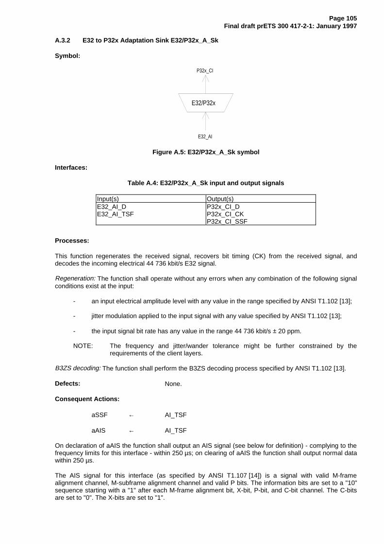
Page 105Final draft prETS 300 417-2-1: January 1997
A.3.2 E32 to P32x Adaptation Sink E32/P32x_A_Sk
Symbol:
E32/P32x
P32x_CI
E32_AI
Figure A.5: E32/P32x_A_Sk symbol
Interfaces:
Table A.4: E32/P32x_A_Sk input and output signals
Input(s) Output(s)E32_AI_DE32_AI_TSF
P32x_CI_DP32x_CI_CKP32x_CI_SSF
Processes:
This function regenerates the received signal, recovers bit timing (CK) from the received signal, anddecodes the incoming electrical 44 736 kbit/s E32 signal.
Regeneration: The function shall operate without any errors when any combination of the following signalconditions exist at the input:
- an input electrical amplitude level with any value in the range specified by ANSI T1.102 [13];
- jitter modulation applied to the input signal with any value specified by ANSI T1.102 [13];
- the input signal bit rate has any value in the range 44 736 kbit/s ± 20 ppm.
NOTE: The frequency and jitter/wander tolerance might be further constrained by therequirements of the client layers.
B3ZS decoding: The function shall perform the B3ZS decoding process specified by ANSI T1.102 [13].
Defects: None.
Consequent Actions:
aSSF ← AI_TSF
aAIS ← AI_TSF
On declaration of aAIS the function shall output an AIS signal (see below for definition) - complying to thefrequency limits for this interface - within 250 µs; on clearing of aAIS the function shall output normal datawithin 250 µs.
The AIS signal for this interface (as specified by ANSI T1.107 [14]) is a signal with valid M-framealignment channel, M-subframe alignment channel and valid P bits. The information bits are set to a "10"sequence starting with a "1" after each M-frame alignment bit, X-bit, P-bit, and C-bit channel. The C-bitsare set to "0". The X-bits are set to "1".

Page 106Final draft prETS 300 417-2-1: January 1997
Defect Correlations: None.
Performance Monitoring: None.

Page 107Final draft prETS 300 417-2-1: January 1997
Annex B (Informative): E11 Section Layer Functions
E11
E11/P11x-L
E11
E11/P11x-L
P11x_CI P11x_CI
E11_CI E11_CI
E11
E11_AI E11_AIL : A M I, B 8Z S
Figure B.1: E11 Section atomic functions
E11 layer CP
The Characteristic Information E11_CI of the intra-station electrical layer CP is a digital, electrical1 544 kbit/s signal of defined amplitude, bit rate and pulse shape specified by ANSI T1.102 [13].
NOTE: The pulse shape defined in ANSI T1.102 [13] is for the signal at the digital distributionframe, not at the connector of the equipment.
E11 layer AP
The information passing across the E11/P11x AP is a 1 544 kbit/s signal with co-directional bit timing.
B.1 E11 Connection function E11_C
For further study.
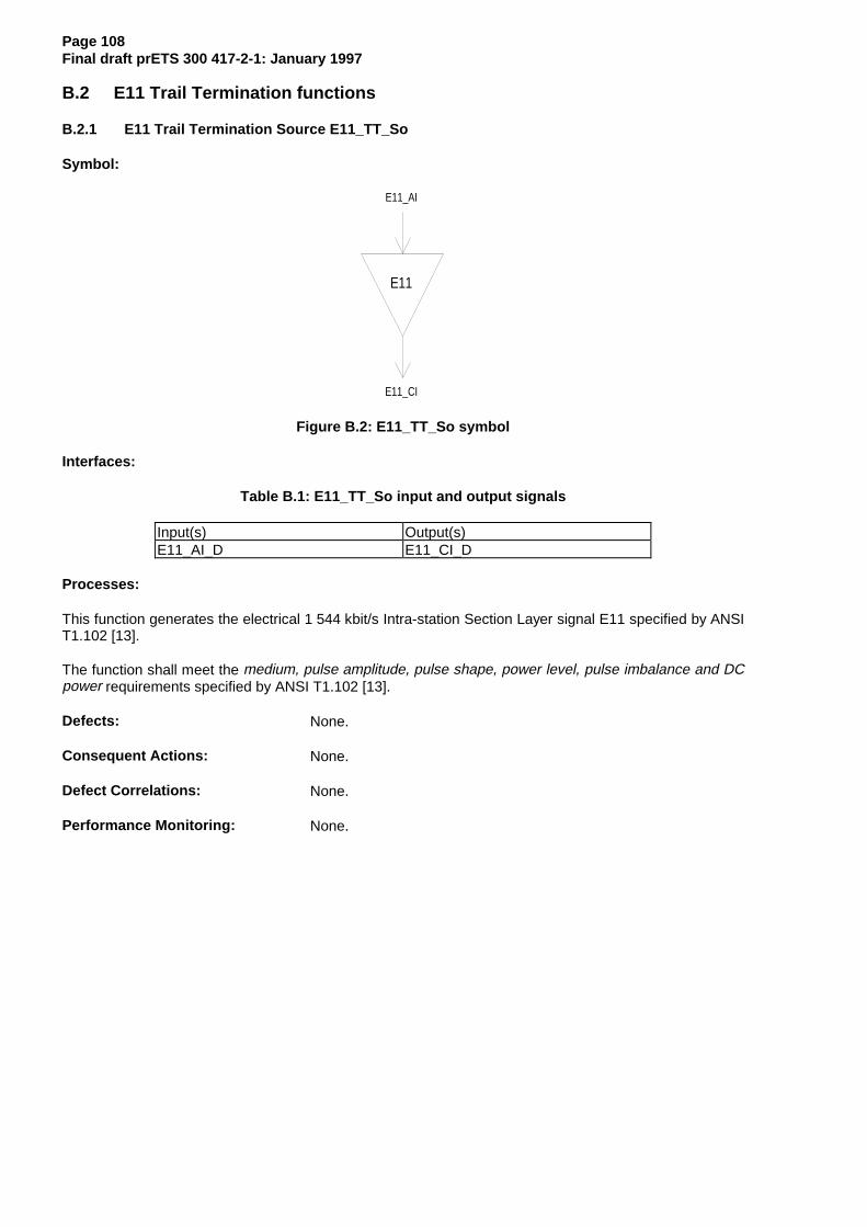
Page 108Final draft prETS 300 417-2-1: January 1997
B.2 E11 Trail Termination functions
B.2.1 E11 Trail Termination Source E11_TT_So
Symbol:
E11
E11_AI
E11_CI
Figure B.2: E11_TT_So symbol
Interfaces:
Table B.1: E11_TT_So input and output signals
Input(s) Output(s)E11_AI_D E11_CI_D
Processes:
This function generates the electrical 1 544 kbit/s Intra-station Section Layer signal E11 specified by ANSIT1.102 [13].
The function shall meet the medium, pulse amplitude, pulse shape, power level, pulse imbalance and DCpower requirements specified by ANSI T1.102 [13].
Defects: None.
Consequent Actions: None.
Defect Correlations: None.
Performance Monitoring: None.

Page 109Final draft prETS 300 417-2-1: January 1997
B.2.2 E11 Trail Termination Sink E11_TT_Sk
Symbol:
E11
E11_AI
E11_CI
E11_TT_Sk_MI
Figure B.3: E11_TT_Sk symbol
Interfaces:
Table B.2: E11_TT_Sk input and output signals
Input(s) Output(s)E11_CI_D
E11_TT_Sk_MI_PortMode
E11_AI_DE11_AI_TSFE11_TT_Sk_MI_cLOS
Processes:
This function recovers the electrical 1 544 kbit/s Intra-station Section Layer signal E11 specified by ANSIT1.102 [13].
Port Mode: The function shall have a port mode as specified by subclause 8.5 of ETS 300 417 -1-1 [1].
NOTE: The AUTO state of the port mode process is optional.
Defects:
The function shall detect Loss Of Signal defect (dLOS) according the 1 544 kbit/s dLOS specification inITU-T Recommendation G.775 [10].
Consequent Actions:
aTSF ← dLOS
Defect Correlations:
cLOS ← MON and dLOS
Performance Monitoring: None.

Page 110Final draft prETS 300 417-2-1: January 1997
B.3 E11 Adaptation functions
B.3.1 E11 to P11x Adaptation Source E11/P11x-L_A_So
NOTE 1: L will be one value out of the set: AMI, B8ZS.
Symbol:
E11/P11x-L
P11x_CI
E11_AI
E11/P11x_A_So_MIL : A M I, B 8Z S
Figure B.4: E11/P11x-L_A_So symbol
Interfaces:
Table B.3: E11/P11x-L_A_So input and output signals
Input(s) Output(s)P11x_CI_DP11x_CI_CKE11/P11x_A_So_MI_Active
E11_AI_D
Processes:
This function provides the line encoding of the 1 544 kbit/s information stream specified by ANSIT1.102 [13].
Line encoder: The function shall perform line encoding of the data as specified ANSI T1.102 [13].
The function shall not add any jitter.
NOTE 2: Jitter at the NNI is the combination of the jitter generated and transferred via the clientlayers.
Defects: None.
Consequent Actions: None.
Defect Correlations: None.
Performance Monitoring: None.
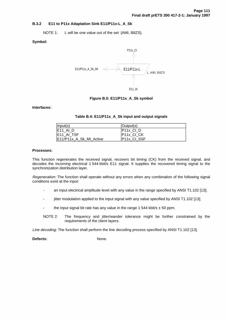
Page 111Final draft prETS 300 417-2-1: January 1997
B.3.2 E11 to P11x Adaptation Sink E11/P11x-L_A_Sk
NOTE 1: L will be one value out of the set: AMI, B8ZS.
Symbol:
E11/P11x-L
P11x_CI
E11_AI
E11/P11x_A_Sk_MIL : A M I, B 8Z S
Figure B.5: E11/P11x_A_Sk symbol
Interfaces:
Table B.4: E11/P11x_A_Sk input and output signals
Input(s) Output(s)E11_AI_DE11_AI_TSFE11/P11x_A_Sk_MI_Active
P11x_CI_DP11x_CI_CKP11x_CI_SSF
Processes:
This function regenerates the received signal, recovers bit timing (CK) from the received signal, anddecodes the incoming electrical 1 544 kbit/s E11 signal. It supplies the recovered timing signal to thesynchronization distribution layer.
Regeneration: The function shall operate without any errors when any combination of the following signalconditions exist at the input:
- an input electrical amplitude level with any value in the range specified by ANSI T1.102 [13];
- jitter modulation applied to the input signal with any value specified by ANSI T1.102 [13];
- the input signal bit rate has any value in the range 1 544 kbit/s ± 50 ppm.
NOTE 2: The frequency and jitter/wander tolerance might be further constrained by therequirements of the client layers.
Line decoding: The function shall perform the line decoding process specified by ANSI T1.102 [13].
Defects: None.

Page 112Final draft prETS 300 417-2-1: January 1997
Consequent Actions:
aSSF ← AI_TSF
aAIS ← AI_TSF
On declaration of aAIS the function shall output an all-ONEs (AIS) signal - complying to the frequencylimits for this interface (e.g. 1 544 kHz ± 50 ppm) - within 250 µs; on clearing of aAIS the function shalloutput normal data within 250 µs.
Defect Correlations: None.
Performance Monitoring: None.

Page 113Final draft prETS 300 417-2-1: January 1997
Annex C (informative): Bibliography
- ITU-T Recommendation V.11 (1993): "Electrical characteristics for balanced double-currentinterchange circuits operating at data signalling rates up to 10 Mbit/s".
- ETS 300 462-3: "Transmission and Multiplexing (TM); Generic requirements for synchronizationnetworks; Part 3: The control of jitter and wander within synchronization networks".

Page 114Final draft prETS 300 417-2-1: January 1997
History
Document history
April 1996 Public Enquiry PE 105: 1996-04-08 to 1996-08-30
January 1997 Vote V 9713: 1997-01-28 to 1997-03-28