final draft united states army military munitions response ... · final draft united states army...
TRANSCRIPT
FINAL DRAFT United States Army Military Munitions Response Program Munitions Response Remedial Investigation / Feasibility Study Guidance October 2008

Final Draft Army MMRP RI/FS Guidance
Final Draft October 2008
This page intentionally left blank.
Final Draft Army MMRP RI/FS Guidance
Final Draft October 2008 i
Contents 1 2 1 Introduction ................................................................................................... 1-1 3
1.1 Purpose ................................................................................................ 1-1 4 1.2 Definitions ............................................................................................. 1-2 5 1.3 Military Munitions Response Program .................................................. 1-4 6
1.3.1 Understanding Munitions Response Sites ................................. 1-5 7 1.3.2 Land Use Considerations........................................................... 1-6 8 1.3.3 Explosives Safety ...................................................................... 1-8 9
1.4 Comprehensive Environmental Response, Compensation, and Liability 10 Act Process Overview .......................................................................... 1-9 11 1.4.1 Remedial Investigation / Feasibility Study Introduction ............ 1-10 12
1.5 Resource Conservation and Recovery Act Corrective Action 13 Overview ............................................................................................ 1-12 14
1.6 Regulatory Interface ........................................................................... 1-14 15 1.6.1 Stakeholder Involvement ......................................................... 1-15 16
2 Programmatic Overview ............................................................................... 2-1 17 2.1 Defense Environmental Restoration Program and the Military Munitions 18
Response Program ............................................................................... 2-1 19 2.1.1 Army Policy for Active Installations ............................................ 2-2 20 2.1.2 Army Policy for Formerly Used Defense Sites ........................... 2-2 21 2.1.3 Army Policy for Base Realignment and Closure ........................ 2-2 22
2.2 Roles and Responsibilities ................................................................... 2-3 23 2.2.1 Department of Defense .............................................................. 2-3 24 2.2.2 U.S. Army .................................................................................. 2-4 25 2.2.3 Installation Management Command and the Assistant Chief of 26
Staff for Installation Management ................................................. 2-4 27 2.2.4 U.S. Army Environmental Command ......................................... 2-5 28 2.2.5 U.S. Army Technical Center for Explosives Safety .................... 2-6 29 2.2.6 U.S. Army Center for Health Promotion and Preventive 30
Medicine ....................................................................................... 2-6 31 2.2.7 U.S. Army Corps of Engineers and the Environmental and 32
Munitions Center of Expertise ...................................................... 2-7 33 2.2.8 Installations ................................................................................ 2-7 34 2.2.9 Regulatory Agencies Jurisdiction Overview ............................... 2-9 35 2.2.10 U.S. Environmental Protection Agency ...................................... 2-9 36 2.2.11 State Regulatory Agencies ........................................................ 2-9 37 2.2.12 Department of Defense and Regulatory Partnerships ............. 2-10 38
3 Management of a Remedial Investigation / Feasibility Study during a 39 Munitions Response ..................................................................................... 3-1 40 3.1 Management of Munitions Response Areas and Munitions Response 41
Sites ..................................................................................................... 3-1 42 3.2 Technical Project Planning Process ..................................................... 3-4 43
3.2.1 Phase I – Identify Current Munitions Response Site Project ...... 3-5 44 3.2.2 Phase II – Determine Data Needs ............................................. 3-6 45 3.2.3 Phase III – Develop Data Collection Options ............................. 3-7 46
Final Draft Army MMRP RI/FS Guidance
Final Draft October 2008 ii
3.2.4 Phase IV – Finalize Data Collection Program ............................ 3-8 1 3.3 Managing Uncertainty ........................................................................... 3-9 2 3.4 Project Management Summary ............... Error! Bookmark not defined. 3
4 Scoping the Remedial Investigation / Feasibility Study ................................ 4-1 4 4.1 Site Understanding and Initial Evaluation – TPP Phase I ..................... 4-2 5
4.1.1 Evaluation of Current Determined or Reasonably Anticipated 6 Land Use and Potential Receptors ............................................... 4-5 7
4.1.2 U.S. Environmental Protection Agency’s Reuse Assessment .... 4-5 8 4.1.3 Conceptual Site Model Evaluation ............................................. 4-6 9 4.1.4 Initial Response Alternative Evaluation .................................... 4-10 10 4.1.5 Initial Applicable or Relevant and Appropriate Requirements 11
Evaluation ................................................................................... 4-11 12 4.1.6 Preliminary Remediation Goals ............................................... 4-12 13
4.2 Determining Data Needs – TPP Phase II ........................................... 4-13 14 4.2.1 Small Arms Ranges ................................................................. 4-16 15 4.2.2 Chemical Warfare Materiel Sites ............................................. 4-16 16 4.2.3 Munitions with an Unknown Liquid Fill ..................................... 4-18 17 4.2.4 Radiological/Depleted Uranium ............................................... 4-18 18 4.2.5 Water Sites (Inland and Ocean) ............................................... 4-20 19 4.2.6 Improved Conventional Munitions and Submunitions .............. 4-20 20
4.3 Develop Data Collection Options – TPP Phase III .............................. 4-21 21 4.4 Finalizing the Data Collection Program – TPP Phase IV .................... 4-22 22
4.4.1 Data Quality Objectives ........................................................... 4-22 23 4.4.2 Work Plan Preparation ............................................................. 4-23 24
4.5 Public Involvement in the Remedial Investigation / Feasibility Study .. 4-28 25 4.5.1 Rights of Entry ......................................................................... 4-29 26
5 Remedial Investigation ................................................................................. 5-1 27 5.1 Site Characterization ............................................................................ 5-3 28 5.2 Munitions Response Site Characterization for Certain Categories of 29
Munitions and Explosives of Concern (Unexploded Ordnance and 30 Discarded Military Munitions) ............................................................... 5-4 31 5.2.1 Technology Selection ................................................................ 5-8 32 5.2.2 Survey Approach Decisions ..................................................... 5-16 33 5.2.3 Use of Statistical Tools ............................................................ 5-18 34 5.2.4 Phenomenological Geophysical Analysis ................................ 5-19 35 5.2.5 Anomaly Discrimination and Data Interpretation ...................... 5-20 36 5.2.6 Anomaly Investigation .............................................................. 5-20 37
5.3 Munitions Constituents Characterization ............................................ 5-21 38 5.3.1 Representative Soil Sampling Methods ................................... 5-26 39 5.3.2 Analytical Methods ................................................................... 5-27 40 5.3.3 Sample Depth and Processing ................................................ 5-31 41 5.3.4 Data Management and Validation ............................................ 5-34 42
5.4 Data Evaluation .................................................................................. 5-34 43 5.5 Baseline Risk/Hazard Assessment ..................................................... 5-37 44
5.5.1 U.S. Environmental Protection Agency Munitions and Explosives 45 of Concern Hazard Assessment ................................................. 5-38 46
Final Draft Army MMRP RI/FS Guidance
Final Draft October 2008 iii
5.5.2 U.S. Army Corps of Engineers Ordnance and Explosives Risk 1 Impact Assessment .................................................................... 5-39 2
5.5.3 Munitions Constituents Risk Assessment ................................ 5-39 3 5.6 Assessment of Required Interim Measures ........................................ 5-40 4
5.6.1 Remedial Actions and Removal Actions .................................. 5-40 5 5.7 Remedial Investigation Reporting ....................................................... 5-42 6
5.7.1 Update Conceptual Site Model ................................................ 5-42 7 5.7.2 Update Munitions Response Site Prioritization Protocol .......... 5-42 8
6 Treatability Studies ....................................................................................... 6-1 9 7 Feasibility Study ........................................................................................... 7-1 10
7.1 Development of Response Actions and Process Options .................... 7-1 11 7.1.1 No Further Action ....................................................................... 7-1 12 7.1.2 Risk Management or Land Use Controls ................................... 7-1 13 7.1.3 Remedial Action with Long-Term Management (Surface and 14
Subsurface Excavation and Disposal) .......................................... 7-5 15 7.2 Development and Screening of Alternatives ......................................... 7-6 16 7.3 Comparison of Alternatives .................................................................. 7-7 17
7.3.1 Threshold Criteria ...................................................................... 7-7 18 7.3.2 Balancing Criteria ...................................................................... 7-8 19 7.3.3 Modifying Criteria ..................................................................... 7-10 20
7.4 Reporting ............................................................................................ 7-11 21 22
23
Final Draft Army MMRP RI/FS Guidance
Final Draft October 2008 iv
List of Figures 1 2 Figure 1-1: CERCLA process ............................................................................ 1-9 3 Figure 1-2: RI/FS process ................................................................................ 1-13 4 Figure 1-3: CERCLA and RCRA Corrective Action comparison ...................... 1-14 5 Figure 2-1: Army environmental organization .................................................... 2-5 6 Figure 2-2: USAEC organizational structure ...................................................... 2-6 7 Figure 3-1: Relationship between MRA and MRS .............................................. 3-3 8 Figure 3-2: TPP process .................................................................................... 3-4 9 Figure 4-1: Scoping the RI/FS ........................................................................... 4-1 10 Figure 4-2: Wire-frame graphical representation of CSM ................................... 4-8 11 Figure 4-3: 3D graphical representation of CSM ................................................ 4-9 12 Figure 5-1: Flow diagram for the RI ................................................................... 5-2 13 Figure 5-2: Example of geophysical data ........................................................... 5-7 14 Figure 5-3: Types of geophysical survey designs ............................................ 5-18 15 Figure 6-1: Treatability study decision diagram ................................................. 6-1 16 17 List of Tables 18 19 Table 1-1: MRS Types ....................................................................................... 1-5 20 Table 3-1: MR Project Team .............................................................................. 3-5 21 Table 3-2: Example Data Needs Categorization ................................................ 3-7 22 Table 3-3: Uncertainty Categorization Matrix ................................................... 3-12 23 Table 4-1: Phase I MFR Components ................................................................ 4-3 24 Table 4-2: Project Objective Worksheet ............................................................. 4-5 25 Table 4-3: CSM Profiles, Information Needs, and Revisions ............................. 4-6 26 Table 4-4: NCP Nine Criteria ........................................................................... 4-10 27 Table 4-5: Examples of Military Munitions that May Contain DU ..................... 4-20 28 Table 5-1: Comparison of RI Components ......................................................... 5-1 29 Table 5-2: Comparison of Detection Technologies .......................................... 5-12 30 Table 5-3: Comparison of Positioning Systems ............................................... 5-15 31 Table 5-4: Comparison of Excavation Technologies ........................................ 5-22 32 Table 5-5: Comparison of Disposal Technologies............................................ 5-23 33 Table 5-6: Commonly Evaluated MC ............................................................... 5-29 34 Table 5-7: Fixed Laboratory Tests for Metals; Perchlorate; and Nitrogen-Based 35 Explosives, Co-contaminants, and Breakdown Products ................................. 5-31 36 Table 5-8: Field Tests for Nitrogen-Based Explosives ..................................... 5-31 37 Table 5-9: MI Sampling Considerations for Various Range Types .................. 5-35 38 Table 7-1: Example Process Options for MEC Remedial Alternatives ............... 7-2 39 40 41
Final Draft Army MMRP RI/FS Guidance
Final Draft October 2008 v
1 Appendices 2 3 Appendix A: References 4 Appendix B: Acronyms and Glossary 5 Appendix C: Regulatory Considerations: State Adoption of the Federal Military 6
Munitions Rule 7 Appendix D: Remedial Project Managers' Guide and Formerly Used Defense Site 8
Public Involvement Toolkit 9 10
Final Draft Army MMRP RI/FS Guidance
Final Draft October 2008 1-1
1 Introduction 1 After generations of munitions-related activities required to maintain our military's 2 readiness, unexploded ordnance (UXO), discarded military munitions (DMM), 3 and munitions constituents (MC) may be present to some degree at many active 4 and former military installations. 5 6 Prior to the National Defense Authorization Act (NDAA) of Fiscal Year (FY) 2002, 7 Congress had informally requested the Department of Defense (DoD) to begin to 8 develop better visibility of the costs associated with UXO. In the FY 2002 NDAA, 9 which modified the Defense Environmental Restoration Project (DERP), 10 Congress directed the DoD to take several actions with regard to UXO, DMM, 11 and MC. These actions included the following: (1) developing and maintaining an 12 inventory of all defense sites known or suspected to contain UXO, DMM or MC; 13 (2) developing a new protocol to prioritize the inventoried sites; and (3) 14 establishing a new program element within the environmental restoration account 15 to track the remediation of UXO, DMM and MC. For many years, the DoD has 16 been responding to properties that were known or suspected to contain UXO or 17 DMM. The DoD established formal Military Munitions Response Program 18 (MMRP) policy in September 2001 to attain a better understanding of MMRP 19 response requirements and gain better visibility of total potential costs. 20 21 The DERP, including the MMRP, follows the process outlined in the 22 Comprehensive Environmental Response, Compensation, and Liability Act 23 (CERCLA) and the National Contingency Plan (NCP). State Adoption of the 24 Federal Military Munitions Rule is listed in Appendix C. As appropriate, a site 25 investigation is conducted to analyze and determine suitable response 26 alternatives. This guidance complements and expands existing Remedial 27 Investigation (RI) / Feasibility Study (FS) guidance, providing focus on the unique 28 nature of sites containing UXO, DMM, and MC (see Appendix A references). 29
1.1 Purpose 30 The purpose of this guidance is to provide Remedial Project Managers (RPMs) 31 (which include assigned government and contractor project managers providing 32 oversight and execution of an RI/FS) with the process and tools to successfully 33 plan and execute an RI/FS at munitions response sites (MRSs) located on active 34 installations, installations undergoing Base Realignment and Closure (BRAC), 35 Formerly Used Defense Sites (FUDS), and other transferred properties. This 36 guidance applies to locations within the United States and does not apply to 37 military munitions resulting from combat operations (10 U.S.C. §2710 [d]). This 38 guidance relies on the RPM’s knowledge and understanding of DERP and the 39 definitions specific to an RI/FS conducted as part of a munitions response under 40 the MMRP and CERCLA, as provided in Section 1.2. 41 42
Final Draft Army MMRP RI/FS Guidance
Final Draft 1-2 October 2008
This guidance document uses examples and call-out boxes to highlight key 1 concepts in managing and executing an RI/FS for an MRS addressed under the 2 MMRP. Where appropriate, program-specific guidance documents are 3 referenced for users to obtain additional detailed information relating to a 4 particular aspect of the MMRP process when applied to an MRS. 5
1.2 Definitions 6 The MMRP uses specialized terminology to categorize and discuss munitions 7 response actions. Terminology and associated definitions used by the MMRP 8 and in this RI/FS guidance are as follows: 9
• Defense site – Any location that is or was owned by, leased to, or 10 otherwise possessed or used by the DoD. The term does not include 11 any operational range, operating storage or manufacturing facility, or 12 facility that is used or was permitted for the treatment or disposal of 13 military munitions. (10 U.S.C. §2710(e)(1)) 14
• Discarded military munitions (DMM) – Military munitions that have 15 been abandoned without proper disposal or removed from storage in a 16 military magazine or other storage area for the purpose of disposal. The 17 term does not include UXO, military munitions that are being held for 18 future use or planned disposal, or military munitions that have been 19 properly disposed of consistent with applicable environmental laws and 20 regulations. (10 U.S.C. §2710(e)(2)) 21
• Explosive ordnance disposal (EOD) – The detection, identification, 22 on-site evaluation, rendering safe, recovery, and final disposal of UXO 23 and of other munitions that have become an imposing danger, for 24 example, by damage or deterioration. 25
• Explosive ordnance disposal (EOD) personnel – Military personnel 26 who have graduated from the Naval School, Explosive Ordnance 27 Disposal; are assigned to a military unit with a service-defined EOD 28 mission; and meet service and assigned unit requirements to perform 29 EOD duties. EOD personnel have received specialized training to 30 address explosive and certain chemical agent hazards during both 31 peacetime and wartime. EOD personnel are trained and equipped to 32 perform render safe procedures (RSPs) on nuclear, biological, chemical, 33 and conventional munitions and on improvised explosive devices. 34
• Explosive ordnance disposal (EOD) unit – A military organization 35 constituted by proper authority; manned with EOD personnel; outfitted 36 with equipment required to perform EOD functions; and assigned an 37 EOD mission. 38
• Military Munitions – All ammunition products and components 39 produced for or used by the armed forces for national defense and 40 security, including ammunition products or components under the 41 control of the DoD, the United States (U.S.) Coast Guard, the 42
Final Draft Army MMRP RI/FS Guidance
Final Draft 1-3 October 2008
Department of Energy, and the National Guard. The term includes 1 confined gaseous, liquid, and solid propellants; explosives; 2 pyrotechnics; chemical and riot control agents, smokes, and 3 incendiaries, including bulk explosives and chemical warfare agents; 4 chemical munitions; rockets; guided and ballistic missiles; bombs; 5 warheads; mortar rounds; artillery ammunition; small arms ammunition; 6 grenades; mines; torpedoes; depth charges; cluster munitions and 7 dispensers; demolition charges; and devices and components thereof. 8 The term does not include wholly inert items, improvised explosive 9 devices, nuclear weapons, or nuclear devices that are managed under 10 the nuclear weapons program of the Department of Energy after all 11 required sanitization operations under the Atomic Energy Act of 1954 12 (42 United States Code [U.S.C.] 2011 et seq.), as amended, have been 13 completed. (10 U.S.C. 10 (e)(4)(A) through (C)) 14
• Munitions and explosives of concern (MEC) – Specific categories of 15 military munitions that may pose unique explosives safety risks and 16 means UXO, as defined in 10 U.S.C. 101(e)(5); DMM, as defined in 10 17 U.S.C. 2710(e)(2); or MC (e.g., explosives), as defined in 10 U.S.C. 18 2710(e)(3), present in high enough concentrations to pose an explosive 19 hazard. (U.S. Army, 2005) 20
• Munitions constituents (MC) – Any material originating from UXO, 21 DMM, or other military munitions, including explosive and nonexplosive 22 materials, and emission, degradation, or breakdown elements of such 23 ordnance or munitions. (10 U.S.C 2710(e)(3)) 24
• Munitions debris – Remnants of military munitions (e.g., fragments, 25 penetrators, projectiles, shell casings, links, fins) remaining after 26 munitions use, demilitarization, or disposal. 27
• Munitions response – Response actions, including investigation, 28 removal actions, and remedial actions to address the explosives safety, 29 human health, or environmental risks presented by UXO, DMM, or MC, 30 or to support a determination that no removal or remedial action is 31 required. 32
• Munitions response area (MRA) – Any area on a defense site that is 33 known or suspected to contain UXO, DMM, or MC. Examples include 34 former ranges and munitions burial areas. An MRA is composed of one 35 or more MRSs (U.S. Army, 2005). 36
• Munitions response site (MRS) – A discrete location within an MRA 37 that is known to require a munitions response. 38
• Other debris – Debris found on operational ranges or MRSs, which 39 may be removed to facilitate a range clearance or munitions response 40 that is not related to munitions or range operations. Such debris 41 includes, but is not limited to, rebar, household items (refrigerators, 42
Final Draft Army MMRP RI/FS Guidance
Final Draft 1-4 October 2008
washing machines, etc.), automobile parts and automobiles that were 1 not associated with range targets, fence posts, and fence wire. 2
• Range-related debris – Debris, other than munitions debris, collected 3 from operational ranges or from former ranges (e.g., targets, target 4 debris, military munitions packaging and crating material). 5
• Small arms ammunition – Ammunition, without projectiles that contain 6 explosives (other than tracers), that is .50-caliber or smaller or for 7 shotguns. 8
• Unexploded ordnance (UXO) – Military munitions that have been 9 primed, fuzed, armed, or otherwise prepared for action; have been fired, 10 dropped, launched, projected, or placed in such a manner as to 11 constitute a hazard to operations, installations, personnel, or material; 12 and remain unexploded either by malfunction, design, or any other 13 cause. (10 U.S.C. 101(e)(5)(A) through (C)) 14
Additional definitions and acronyms related to conducting an MMRP RI/FS are 15 provided in Appendix B. 16
1.3 Military Munitions Response Program 17 The U.S. Army completed an initial inventory of MRSs (formerly referred to as 18 closed, transferred, and transferring military ranges) eligible for munitions 19 responses under the MMRP. Under the MMRP, the Army may conduct munitions 20 response activities at active and BRAC installations and FUDS in accordance 21 with the following funding eligibility criteria for: 22
• MMRP sites at active installations, if: 23 ° the release occurred prior to 30 September 2002; and 24 ° the release is at a site that is not an operational range, an active 25
munitions demilitarization facility, or an active waste military 26 munitions treatment or disposal unit that operated after 30 27 September 2002; and 28
° the site’s MMRP costs were not identified or included in the Army 29 Environmental Database – Restoration prior to 30 September 2000. 30
• BRAC MMRP sites, if: 31 ° the release occurred prior to 30 September 2002; and 32 ° the release is at a site that is not an operational range, an active 33
munitions demilitarization facility, or an active waste military 34 munitions treatment or disposal unit that operated after 30 35 September 2002; and 36
° the site’s MMRP costs were not identified or included in the Army 37 Environmental Database – Restoration prior to 30 September 2000. 38
39

Final Draft Army MMRP RI/FS Guidance
Final Draft 1-5 October 2008
• FUDS MMRP sites, if: 1 ° the release occurred prior to 17 October 1986; and 2 ° the property was transferred from DoD control prior to 17 October 3
1986; and 4 ° the property or project meets other Environmental Restoration – 5
FUDS eligibility criteria. 6 7 Funds appropriated to conduct MMRP actions cannot be used for: 8
• locations outside of the United States or territories; 9 • the presence of military munitions resulting from combat operations; 10 • operational ranges (previously defined as active or inactive ranges); or 11 • a facility that is used or was permitted for the treatment or disposal of 12
military munitions at permitted open burn (OB) / open detonation (OD) 13 sites. 14
1.3.1 Understanding Munitions Response Sites 15 UXO, DMM, and MC may be present as a result of munitions-related activities 16 (e.g., live-fire training and testing, munitions manufacturing or maintenance, 17 munitions demilitarization). For example, UXO may be present if munitions fired 18 on a range malfunction. DMM may be present on former ranges as a result of the 19 historical practice of burying excess, obsolete, or unserviceable military 20 munitions. MC may be generated from munitions-related activities, including, but 21 not limited to, use, production, or demilitarization. Table 1-1 provides common 22 types of MRSs. 23 24
Table 1-1: MRS Types 25
MRS Type Typical Munitions Used Possible
UXO/DMM/MC Small arms range Small arms ammunition DMM and MC Grenade range Hand and rifle grenades UXO, DMM, and MC Artillery range Medium and large caliber projectiles (Some
ranges may contain submunitions from the use of improved conventional munitions [ICMs].)
UXO, DMM, and MC
Bombing range Bombs (Some ranges may contain submunitions from the use of ICMs.)
UXO, DMM, and MC
Air-to-air range Small arms ammunition MC Air-to-ground range Small arms ammunition, medium and large
caliber projectiles, rockets, and guided missiles
UXO, DMM, and MC
Ground-to-air range Small arms ammunition, projectiles, rockets, and guided missiles
UXO, DMM, and MC
Ground-to-ground range
Rockets and guided missiles UXO, DMM, and MC

Final Draft Army MMRP RI/FS Guidance
Final Draft 1-6 October 2008
MRS Type Typical Munitions Used Possible
UXO/DMM/MC Multiple use range Small arms ammunition, medium and large
caliber projectiles, grenades, rockets, and bombs
UXO, DMM, and MC
Training/maneuver area Small arms ammunition, signals, trip flares, and other training devices
UXO, DMM, and MC
OB/OD area Various military munitions (If permitted, the OB/OD area would not be eligible for the MMRP.)
UXO, DMM, and MC
Military munitions manufacturing facility
Explosives residues, soils at concentrations high enough to pose an explosive hazard
MC
Storage area transfer point
Various unused military munitions DMM and MC
Firing point Various military munitions DMM and MC Burial pit Various unused military munitions DMM and MC Adapted from Engineer Manual (EM) 1110-1-1200 (USACE, 2003k) 1 2 Munitions response alternatives for both MEC and MC under the MMRP, which 3 may be used individually or in combination, are identified below. 4 5 Typical MEC Response Alternatives: 6
° No further action (NFA) 7 ° Explosives safety education (3Rs--recognize, retreat, report) 8 ° Land use controls (LUCs) 9 ° Surface removal plus LUCs or subsurface removal plus LUCs 10 ° Long-term management (LTM) 11 ° Recurring reviews 12
Typical MC Response Alternatives: 13 ° NFA 14 ° Containment actions 15 ° Removal or collection actions / LUCS 16 ° Treatment actions 17 ° LTM 18 ° Recurring reviews 19
20 Further discussion of the specific alternatives available and the development and 21 analysis of alternatives is provided in Section 7. 22
1.3.2 Land Use Considerations 23 Key to all decisions made when designing a munitions response under the 24 MMRP is understanding the munitions-related activities that may have occurred 25 on the property, the property's ownership, and its current, determined, or 26 reasonably anticipated future use. Active and BRAC installations have varying 27 degrees of control over the use of the MRS that they are addressing. The amount 28 of control is less certain for property transferred outside DoD control (e.g., 29 FUDS). Although the active, FUDS, and BRAC programs seek to reduce the 30
Final Draft Army MMRP RI/FS Guidance
Final Draft 1-7 October 2008
hazard from exposure to UXO, DMM, and MC, certain limitations exist among 1 various programs. 2 3 By DoD policy, the Army seeks to focus efforts on addressing the MRS posing 4 the highest relative risk before addressing ones of lower relative risk. Generally, 5 these are MRSs where access cannot be controlled and MEC are known or 6 suspected to be present on the surface. 7 8 The following land use considerations guide the Army’s MMRP: 9
• Does the DoD control the property? 10 ° If an MRS is located on an active Army installation, the Army can 11
control the future use of the site. 12 ° The Army does not control the land use for an MRS that is not 13
under DoD control (e.g., transferred from an active installation or 14 FUDS) and may have limited control of an MRS that is being 15 transferred from DoD control (e.g., BRAC). 16
• Will the existing land use change in the future? Is there a 17 reasonably anticipated future land use? 18 ° At an active Army MRS within installation boundaries, the RPM and 19
the installation planning department work together to identify 20 current and reasonably anticipated future land uses. 21
° The reuse plan established by the controlling authorities delineates 22 reasonably anticipated land use at installations being closed under 23 BRAC, and installations must be understood by the RPM. 24
° FUDS policy generally requires that established land use be 25 considered in the design of a munitions response. The objective of 26 LUCs is to ensure that reasonably anticipated future land use 27 remains compatible with the land use that was the basis for the 28 evaluation, selection, and implementation of the response action. 29
• Can the existing or reasonably anticipated future land use be 30 changed to protect against potential explosives, chemical warfare 31 material, or human health hazards? 32 ° For an MRS within an active Army installation’s boundaries, the 33
RPM may be able to recommend changes in land use that allow for 34 the property's safe use, given any hazards present and any 35 response performed. 36
° At BRAC installations, the RPM and the reuse planners can work 37 together to identify areas where the presence of UXO, DMM, or MC 38 influences redevelopment and to identify uses that would allow the 39 property's safe use, given any hazards present and any response 40 performed. 41

Final Draft Army MMRP RI/FS Guidance
Final Draft 1-8 October 2008
° Although FUDS policy generally requires that only established land 1 use be considered, the FUDS RPM may, in collaboration with state 2 and federal regulators and the property owner, identify any 3 concerns with current or reasonably anticipated future land use. 4
• Can LUCs be established to protect against potential hazards 5 associated with the known or suspected presence of UXO, DMM, or 6 MC? 7 ° Land uses of an MRS on an active installation can be controlled to 8
reduce the potential impact of any hazards present. 9 ° BRAC installations must ensure that protective measures are in 10
place to address any potential hazard known or suspected to be 11 present before the property is transferred. See Army Regulation 12 (AR) 200-1 (U.S. Army, 2007a) and the BRAC Realignment and 13 Redevelopment Manual (DoD, January 2006a) for more 14 information. 15
° Because the Army has no control over the land use of an MRS 16 outside of active installation boundaries, establishing LUCs for a 17 FUDS or parcels transferred from active installations is more 18 complicated. Further discussion of LUCs is provided in Section 7. 19
1.3.3 Explosives Safety 20 By their nature, MEC encounters are 21 potentially hazardous. Protective 22 measures and certain calculated risks 23 are taken to minimize potential 24 hazards during munitions responses 25 that involve or potentially involve 26 MEC. Judgment, common sense, 27 and, above all, compliance with 28 established explosives safety 29 procedures, including the use of 30 qualified personnel and compliance 31 with established procedures help 32 ensure the safety of munitions 33 response activities. EOD/UXO-34 qualified personnel are the most 35 experienced and the only qualified 36 persons to perform or oversee 37 munitions response activities that 38 potentially involve encounters with 39 MEC. 40 41 Explosives safety is paramount during a munitions response to MEC. Per DoD 42 6055.9-STD DoD Ammunition and Explosives Safety Standards (DDESB, 2008) 43
Explosive Safety: Explosives safety is the paramount priority during a munitions response to MEC. The golden rule of explosives safety is to "limit the exposure to a
• minimum number of persons,
• for a minimum time, • to the minimum amount of
military munitions consistent with safe and efficient operations."
This principle also applies during MMRP responses.
Final Draft Army MMRP RI/FS Guidance
Final Draft 1-9 October 2008
and Department of the Army (DA) Pamphlet (PAM) 385-63 (2003b), it is DoD and 1 Army policy to provide the maximum possible protection to people and property 2 from the potential damaging effects of DoD military munitions and to minimize 3 exposures consistent with safe and efficient operations (i.e., expose the minimum 4 number of people for the minimum time to the minimum amount of explosives or 5 chemical agents). These policies apply equally to DoD personnel and DoD 6 contractors performing munitions responses. The most important considerations 7 throughout all aspects of munitions response activities that involve or potentially 8 involve MEC are the safety and health of on-site personnel. All actions taken 9 during a munitions response to MEC are planned to provide for the safety and 10 health of on-site workers and the public. 11 12 During munitions response activities that involve or potentially involve MEC, it is 13 important that everyone involved, including the regulators and stakeholders, 14 understands the potential explosive hazards inherent with MEC. Familiarity with 15 the Army’s UXO Safety Education Program and adherence to the 3 Rs of UXO 16 Safety (Recognize, Retreat, Report) are required of all personnel involved with 17 munitions responses to MEC. For additional information on UXO safety 18 education and the 3 Rs of UXO Safety, visit the DoD UXO Safety Education 19 Program Web site (https://www.denix.osd.mil/UXOSafety). 20
1.4 Comprehensive Environmental Response, Compensation, 21 and Liability Act Process Overview 22
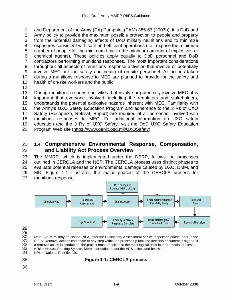
The MMRP, which is implemented under the DERP, follows the processes 23 outlined in CERCLA and the NCP. The CERCLA process uses distinct phases to 24 evaluate potential releases or environmental damage caused by UXO, DMM, and 25 MC. Figure 1-1 illustrates the major phases of the CERCLA process for 26 munitions response. 27
28 29
Note: An MRS may be closed (NFA) after the Preliminary Assessment or Site Inspection phase, prior to the 30 RI/FS. Removal actions can occur at any step within the process up until the decision document is signed. If 31 a removal action is conducted, the project must transition to the most logical point in the remedial process. 32 HRS = Hazard Ranking System. More information about the HRS is included below. 33 NPL = National Priorities List 34
Figure 1-1: CERCLA process 35 36
Feasibility StudySite Discovery
Remedy In Place / Response Complete
Preliminary Assessment & Site Inspection
Remedial InvestigationFeasibility Study
ProposedPlan
Record of DecisionRemedial Design &
Remedial Action
Site Discovery
Remedy In Place / Response Complete5-year Review
HRS Scoring and Potentially NPL Listing
Preliminary Assessment Site Inspection
Final Draft Army MMRP RI/FS Guidance
Final Draft 1-10 October 2008
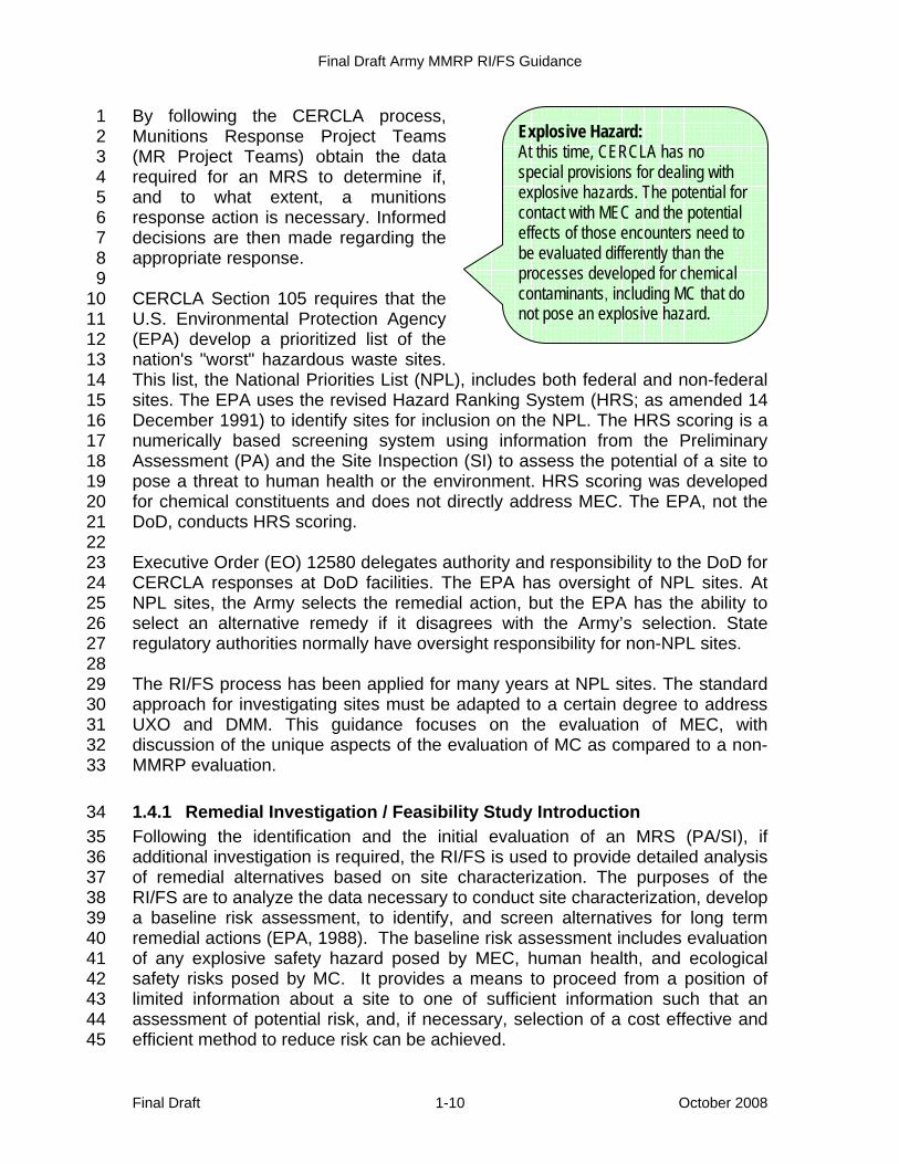
By following the CERCLA process, 1 Munitions Response Project Teams 2 (MR Project Teams) obtain the data 3 required for an MRS to determine if, 4 and to what extent, a munitions 5 response action is necessary. Informed 6 decisions are then made regarding the 7 appropriate response. 8 9 CERCLA Section 105 requires that the 10 U.S. Environmental Protection Agency 11 (EPA) develop a prioritized list of the 12 nation's "worst" hazardous waste sites. 13 This list, the National Priorities List (NPL), includes both federal and non-federal 14 sites. The EPA uses the revised Hazard Ranking System (HRS; as amended 14 15 December 1991) to identify sites for inclusion on the NPL. The HRS scoring is a 16 numerically based screening system using information from the Preliminary 17 Assessment (PA) and the Site Inspection (SI) to assess the potential of a site to 18 pose a threat to human health or the environment. HRS scoring was developed 19 for chemical constituents and does not directly address MEC. The EPA, not the 20 DoD, conducts HRS scoring. 21 22 Executive Order (EO) 12580 delegates authority and responsibility to the DoD for 23 CERCLA responses at DoD facilities. The EPA has oversight of NPL sites. At 24 NPL sites, the Army selects the remedial action, but the EPA has the ability to 25 select an alternative remedy if it disagrees with the Army’s selection. State 26 regulatory authorities normally have oversight responsibility for non-NPL sites. 27 28 The RI/FS process has been applied for many years at NPL sites. The standard 29 approach for investigating sites must be adapted to a certain degree to address 30 UXO and DMM. This guidance focuses on the evaluation of MEC, with 31 discussion of the unique aspects of the evaluation of MC as compared to a non-32 MMRP evaluation. 33
1.4.1 Remedial Investigation / Feasibility Study Introduction 34 Following the identification and the initial evaluation of an MRS (PA/SI), if 35 additional investigation is required, the RI/FS is used to provide detailed analysis 36 of remedial alternatives based on site characterization. The purposes of the 37 RI/FS are to analyze the data necessary to conduct site characterization, develop 38 a baseline risk assessment, to identify, and screen alternatives for long term 39 remedial actions (EPA, 1988). The baseline risk assessment includes evaluation 40 of any explosive safety hazard posed by MEC, human health, and ecological 41 safety risks posed by MC. It provides a means to proceed from a position of 42 limited information about a site to one of sufficient information such that an 43 assessment of potential risk, and, if necessary, selection of a cost effective and 44 efficient method to reduce risk can be achieved. 45
Explosive Hazard: At this time, CERCLA has no special provisions for dealing with explosive hazards. The potential for contact with MEC and the potential effects of those encounters need to be evaluated differently than the processes developed for chemical contaminants, including MC that do not pose an explosive hazard.
Final Draft Army MMRP RI/FS Guidance
Final Draft 1-11 October 2008
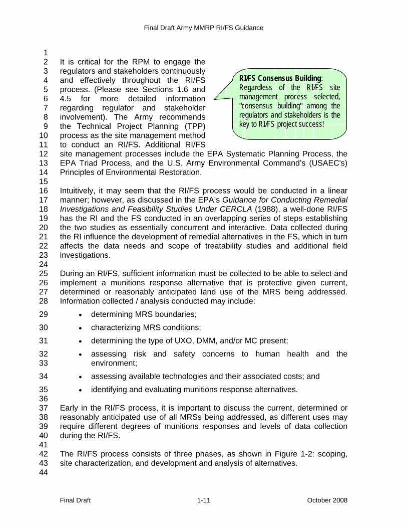
1 It is critical for the RPM to engage the 2 regulators and stakeholders continuously 3 and effectively throughout the RI/FS 4 process. (Please see Sections 1.6 and 5 4.5 for more detailed information 6 regarding regulator and stakeholder 7 involvement). The Army recommends 8 the Technical Project Planning (TPP) 9 process as the site management method 10 to conduct an RI/FS. Additional RI/FS 11 site management processes include the EPA Systematic Planning Process, the 12 EPA Triad Process, and the U.S. Army Environmental Command’s (USAEC's) 13 Principles of Environmental Restoration. 14 15 Intuitively, it may seem that the RI/FS process would be conducted in a linear 16 manner; however, as discussed in the EPA’s Guidance for Conducting Remedial 17 Investigations and Feasibility Studies Under CERCLA (1988), a well-done RI/FS 18 has the RI and the FS conducted in an overlapping series of steps establishing 19 the two studies as essentially concurrent and interactive. Data collected during 20 the RI influence the development of remedial alternatives in the FS, which in turn 21 affects the data needs and scope of treatability studies and additional field 22 investigations. 23 24 During an RI/FS, sufficient information must be collected to be able to select and 25 implement a munitions response alternative that is protective given current, 26 determined or reasonably anticipated land use of the MRS being addressed. 27 Information collected / analysis conducted may include: 28
• determining MRS boundaries; 29 • characterizing MRS conditions; 30 • determining the type of UXO, DMM, and/or MC present; 31 • assessing risk and safety concerns to human health and the 32
environment; 33 • assessing available technologies and their associated costs; and 34 • identifying and evaluating munitions response alternatives. 35
36 Early in the RI/FS process, it is important to discuss the current, determined or 37 reasonably anticipated use of all MRSs being addressed, as different uses may 38 require different degrees of munitions responses and levels of data collection 39 during the RI/FS. 40 41 The RI/FS process consists of three phases, as shown in Figure 1-2: scoping, 42 site characterization, and development and analysis of alternatives. 43 44
RI/FS Consensus Building: Regardless of the RI/FS site management process selected, "consensus building" among the regulators and stakeholders is the key to RI/FS project success!

Final Draft Army MMRP RI/FS Guidance
Final Draft 1-12 October 2008
Scoping is the initial planning phase of the RI/FS process, and many of the 1 planning steps begun here are continued and refined in later phases of the 2 RI/FS. Existing site data, including data from previous investigations, are 3 evaluated to determine the need for and develop initial approaches for further 4 site characterization and the evaluation of response alternatives. The RI/FS 5 scoping process is discussed further in Section 4. 6 7 Site characterization includes performing any necessary field investigation, 8 developing an MC risk assessment, developing a risk/hazard assessment, and 9 conducting treatability studies as needed. The processes and tools used for 10 characterizing an MRS are discussed further in Section 5. Treatability studies are 11 discussed in Section 6. 12 13 Development and detailed analysis of alternatives usually begins during 14 scoping, when likely cleanup scenarios are first identified. Using the information 15 gathered during the site characterization, the alternatives are evaluated based on 16 nine criteria established in the NCP. Further discussion of the specific 17 alternatives available and the development and analysis of alternatives is 18 provided in Section 7. 19
1.5 Resource Conservation and Recovery Act Corrective Action 20 Overview 21
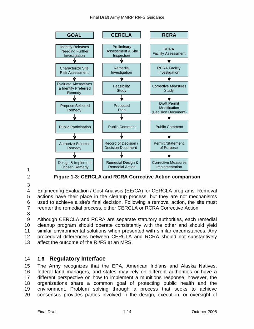
While the DoD prefers to conduct the MMRP under CERCLA, the Army 22 recognizes that some installations may be required to address an MRS under the 23 Resource Conservation and Recovery Act (RCRA) Corrective Action process. It 24 should be noted that RCRA-permitted sites are normally ineligible for the MMRP 25 and will continue to be addressed under RCRA programs. 26 27 Both CERCLA responses and RCRA Corrective Action responses are executed 28 through comparable processes that include an initial site evaluation, a detailed SI 29 and assessment, and ultimately, the design and implementation of the chosen 30 remedy. The comparison of the processes used for each of these programs is 31 shown in Figure 1-3. 32 33 Both programs also allow for short-term 34 remedial actions referred to as removal 35 actions under CERCLA or interim 36 remedial actions and interim response 37 measures under RCRA Corrective 38 Action. Decisions regarding short-term 39 removal actions are developed using an 40 41
CERCLA and RCRA RI/FS Process: The RPM should realize that any procedural differences between CERCLA and RCRA should not substantively affect the outcome of the RI/FS munitions response action.

Final Draft Army MMRP RI/FS Guidance
Final Draft 1-13 October 2008
1
2 3 Note: 4 ARAR = applicable or relevant and appropriate requirement 5 CSM = conceptual site model 6 DD = decision document 7 DQO = data quality objective 8 GPO = geophysical prove-out 9 NTCRA = non-time-critical removal action 10 ROD = record of decision 11 TCRA = time-critical removal action 12
Figure 1-2: RI/FS process 13
From:PA/SI,
TCRA, NTCRAInterim Remedial Action
Scoping of the RI/FS:• Conduct systematic planning or TPP process
§ Collect and analyze existing data§ Identify land use, likely response scenarios, and remedial actions§ Initiate Federal/State ARAR identif ication§ Ref ine initial DQOs and CSM§ Prepare project plans and objectives
• Assess GPO options
Interim / TreatibilityStudies:• Perform as necessary
Site Characterization:• Conduct f ield investigation• Characterize UXO, DMM, and MC• Initial identif ication ofARARs• Conduct baseline risk assessmentbased on UXO, DMM, or MCknown or suspected to be present
RIInterim / TreatibilityStudies:• Perform as necessary
Site Characterization:• Conduct f ield investigation• Characterize UXO, DMM, and MC• Initial identif ication of ARARs• Conduct MC risk assessment andMEC hazard assessment basedon UXO, DMM, or MC known orsuspected to be present
RI
Detailed Analysis of Alternatives• Further ref ine alternatives as necessary• Analyze individual alternatives against thenine criteria
• Compare alternatives against each other
Development and Screening ofAlternatives
• Identify potential technologies• Screen technologies• Assemble technologies into alternatives• Screen alternatives to reduce numbersubject to detailed analysis
• Preserve an appropriate range of options
FSDetailed Analysis of Alternatives• Further ref ine alternatives as necessary• Analyze individual alternatives against thenine NCP criteria
• Compare alternatives against each other
Development and Screening ofAlternatives
• Identify potential technologies• Screen technologies• Assemble technologies into alternatives• Screen alternatives to reduce numbersubject to detailed analysis
• Preserve an appropriate range of options
FS
To:• Proposed Plan• ROD/DD• Remedial Design• Remedial Action
A removal action can
occur whenever
necessary!
Final Draft Army MMRP RI/FS Guidance
Final Draft 1-14 October 2008
1 Figure 1-3: CERCLA and RCRA Corrective Action comparison 2
3 Engineering Evaluation / Cost Analysis (EE/CA) for CERCLA programs. Removal 4 actions have their place in the cleanup process, but they are not mechanisms 5 used to achieve a site's final decision. Following a removal action, the site must 6 reenter the remedial process, either CERCLA or RCRA Corrective Action. 7 8 Although CERCLA and RCRA are separate statutory authorities, each remedial 9 cleanup program should operate consistently with the other and should yield 10 similar environmental solutions when presented with similar circumstances. Any 11 procedural differences between CERCLA and RCRA should not substantively 12 affect the outcome of the RI/FS at an MRS. 13
1.6 Regulatory Interface 14 The Army recognizes that the EPA, American Indians and Alaska Natives, 15 federal land managers, and states may rely on different authorities or have a 16 different perspective on how to implement a munitions response; however, the 17 organizations share a common goal of protecting public health and the 18 environment. Problem solving through a process that seeks to achieve 19 consensus provides parties involved in the design, execution, or oversight of 20
Goal GOAL
Identify ReleasesNeeding Further
Investigation
Characterize Site,Risk Assessment
Evaluate Alternatives & Identify Preferred
Remedy
Propose Selected Remedy
Public Participation
Authorize SelectedRemedy
Design & ImplementChosen Remedy
GoalCERCLA
Preliminary Assessment & Site
Inspection
RemedialInvestigation
FeasibilityStudy
ProposedPlan
Public Comment
Record of Decision /Decision Document
Remedial Design & Remedial Action
GoalRCRA
RCRAFacility Assessment
RCRA Facility Investigation
Corrective Measures Study
Draft Permit Modification
(Decision Document)
Public Comment
Permit /Statement of Purpose
Corrective Measures Implementation

Final Draft Army MMRP RI/FS Guidance
Final Draft 1-15 October 2008
munitions responses a means of resolving differences without denying the 1 parties an opportunity to exercise their respective authorities should the process 2 fail to achieve mutual agreement. To provide the Army's consensus approach the 3 greatest possibility of success, organizations responsible for munitions 4 responses should work in a collaborative manner with environmental regulators 5 and safety officials to attempt to achieve mutual agreement (consensus) 6 throughout the response process, but particularly at critical decision points. 7 Simply put, the Army approach to munitions responses should seek to establish 8 a cooperative working relationship with environmental regulators and safety 9 officials, encouraging respect for other views and efforts to achieve Army goals. 10 Army organizations responsible for the conduct of munitions responses should 11 attempt to arrive at mutually acceptable solutions that incorporate the following 12 principles: 13
• Establishing a collaborative (cooperative) working relationship with 14 environmental regulators and safety officials to achieve mutual 15 agreement (consensus) throughout the response process, but 16 particularly at critical decision points 17
• Raising, when mutual agreement cannot be achieved at one level, the 18 matter to the next level of authority to attempt resolution using the 19 collaborative decision-making process 20
• Acknowledging, when issues of authority arise, the differing opinions 21 and seeking to focus on areas related to the substantive aspects of the 22 munitions response, rather than addressing the authorities issue through 23 a formal exchange of legal opinions 24
1.6.1 Stakeholder Involvement 25 The Army recognizes the benefit and importance of stakeholder involvement in 26 the munitions response process as early as possible and throughout the process. 27 Stakeholder involvement is an effective way to identify and address stakeholder 28 concerns about environmental and safety issues related to an MRS. For 29 stakeholder involvement to be successful, effective two-way communication is 30 necessary. The Army believes that a proactive stakeholder involvement program 31 facilitates the munitions response process and helps ensure the protection of 32 human health and the environment. 33

Final Draft Army MMRP RI/FS Guidance
Draft Final October 2008 2-1
2 Programmatic Overview 1 This section includes a brief overview of current Army DERP and MMRP policies, 2 the DoD and Army environmental organizational structures, and the roles and 3 responsibilities including interaction and partnership with applicable regulatory 4 agencies. 5
2.1 Defense Environmental Restoration Program and the 6 Military Munitions Response Program 7
The DERP was formally established by Congress in 1986 and is codified at 10 8 U.S.C. §2701–2710. The program provides for the cleanup of DoD hazardous 9 waste sites consistent with the provisions of CERCLA as amended by the 10 Superfund Amendments and Reauthorization Act (SARA) Section 211; the NCP 11 (40 Code of Federal Regulations [CFR] §300); and EO 12580, Superfund 12 Implementation. 13 14 The DoD Management Guidance for the Defense Environmental Restoration 15 Program addresses active installations, installations undergoing BRAC, and 16 FUDS. This guidance contains three program categories: the Installation 17 Restoration Program (IRP), the MMRP, and the Building Demolition / Debris 18 Removal Program (DoD, 2001a). 19 20 Under 10 U.S.C. §2701(a)(2), remedial actions taken under the DERP to address 21 releases of hazardous substances and pollutants and contaminants (as defined 22 by CERCLA, as amended) must be conducted under CERCLA, as amended, and 23 the NCP (DoD, 2001a). As a matter of DoD policy, munitions responses are 24 conducted per CERCLA, as amended, and the NCP. 25 26 The NDAA for FY 2002 (Public Law 107-107) formally amended the DERP by 27 establishing the MMRP as a new program element for the cleanup of property 28 known or suspected to contain UXO, DMM, or MC. 29 30 DERP and MMRP policy states that the Army: 31
• exercises its authority, expertise, and responsibility to protect DoD 32 personnel, the public, and the environment from explosive safety risks 33 presented by UXO, DMM, or MC; 34
• conducts munitions responses per CERCLA, the NCP, and applicable 35 federal and state laws; 36
• conducts environmental restoration responses in a manner that does not 37 compromise explosives safety; 38
• integrates, to the extent practicable, munitions responses with other 39 environmental responses; 40
Final Draft Army MMRP RI/FS Guidance
Final Draft 2-2 October 2008
• considers reasonably anticipated future land use in the design and 1 implementation of a munitions response action; 2
• bases munitions response activities on site-specific data and uses best 3 available and appropriate technologies and methods; 4
• provides, to the fullest extent practicable, the opportunity for meaningful 5 involvement of other federal agencies; state, tribal, and local 6 governments; and members of the public in the munitions response 7 process; and 8
• establishes and maintains an inventory of MRSs and a process for 9 assigning a relative priority for munitions response actions. 10
Detailed objectives, targets, success indicators, reporting mechanisms, and 11 management review processes applicable to the MMRP are included in the Army 12 Environmental Cleanup Strategic Plan (U.S. Army, 2007). 13
2.1.1 Army Policy for Active Installations 14 The Army’s MMRP integrates, to the extent practicable, munitions responses 15 with other environmental responses and conducts such responses in a manner 16 that does not compromise explosives safety. It does so while sustaining its ability 17 to preserve the installation infrastructure needed to maintain a trained and ready 18 Army. For active installations, the Army Defense Environmental Restoration 19 Program Management Guidance for Active Installations provides background 20 information, outlines roles and responsibilities, and provides guidance on the 21 management and execution of the Army IRP and MMRP (U.S. Army, 2004a). 22
2.1.2 Army Policy for Formerly Used Defense Sites 23 The U.S. Army Corps of Engineers (USACE) Engineer Regulation (ER) 200-3-1 24 Environmental Quality—Formerly Used Defense Sites (FUDS) Program Policy 25 provides USACE Districts the framework for the implementation of DoD and 26 Army policy governing the FUDS program. Currently, FUDS policy applies to real 27 property that was under the jurisdiction of the Secretary and owned by, leased 28 by, or otherwise possessed by the United States (including governmental entities 29 that are the legal predecessors of the DoD or the components) and those real 30 properties where accountability rested with the DoD but where the activities at 31 the property were conducted by contractors (i.e., government-owned, contractor-32 operated properties) that were transferred from DoD control prior to 17 October 33 1986. The Army is the Executive Agent for the FUDS program. USACE executes 34 and provides day-to-day management of the program for the Army. 35
2.1.3 Army Policy for Base Realignment and Closure 36 The Army established its BRAC program to meet the requirements of the Base 37 Closure and Realignment Act of 1988 and the Defense Base Closure and 38 Realignment Act of 1990, as amended. The BRAC program is charged with 39 closing and realigning military installations. The Base Redevelopment and 40
Final Draft Army MMRP RI/FS Guidance
Final Draft 2-3 October 2008
Realignment Manual (DoD, 2006a) and the Army Defense Environmental 1 Restoration Program Management Guidance for BRAC Installations (U.S. Army, 2 2004b) provide background information, outline roles and responsibilities, and 3 provide guidance on the management and execution of the Army BRAC 4 Environmental Restoration Program, including the MMRP. The goals of the Army 5 BRAC Environmental Restoration Program are to reduce risk to protect human 6 health and the environment and to comply with legally enforceable agreements, 7 orders, and laws through implementation of cost-effective remedial actions, while 8 concurrently effecting timely property transfer (U.S. Army, 2004b). 9
2.2 Roles and Responsibilities 10
2.2.1 Department of Defense 11 The Deputy Under Secretary of Defense for Installations and Environment 12 (DUSD(I&E)) establishes DERP policy and program goals and provides program 13 management oversight. 14 15 The Department of Defense Explosives Safety Board (DDESB) establishes 16 explosives safety standards (DoD 6055.09-STD [2008]; DDESB, 2008), policy, 17 and guidance applicable to the life cycle (i.e., research, development, and 18 testing; hazard classification; production; transportation; handling; storage; 19 inspection; maintenance; use; and disposition) of DoD military munitions. It also 20 establishes such standards for the conduct of munitions and other environmental 21 response at real property known or suspected to contain MEC, including 22 chemical munitions and chemical agent in other than munitions configurations. 23 24 The services’ Explosive Safety Offices (for the Army, the U.S. Army Technical 25 Center for Explosives Safety [USATCES]) and the DDESB help ensure 26 explosives safety throughout the conduct of a munitions response to MEC by 27 ensuring the adequacy of protective measures and compliance with DoD 6055.9-28 STD (DDESB, 2008). The USATCES formally reviews, evaluates, and provides 29 Army approval of measures to protect Army employees and the public from the 30 potential hazards associated with munitions responses to MEC. USATCES also 31 ensures that the design of a munitions response to MEC addresses any residual 32 explosive hazards potentially present at an MRS after completion of such 33 responses. 34 35 The DDESB staff performs a technical review of required submissions and 36 recommends approval or disapproval, as appropriate, by the Chair, DDESB, on 37 behalf of the DDESB. Although the DDESB requires other safety submissions, 38 for explosives safety for remedial investigation purposes, the submission 39 normally used for a munitions response to MEC is the munitions response 40 Explosive Safety Plan (ESP). For a munitions response that may involve 41 chemical warfare material (CWM) (i.e., chemical munitions and chemical agents 42 in other than munitions configurations; referred to as CWM responses), a 43

Final Draft Army MMRP RI/FS Guidance
Final Draft 2-4 October 2008
munitions response Chemical Safety Plan (CSP) is required. When the work is to 1 be performed for the remedial or removal action, a Munitions Response 2 Explosive Safety Submission (MRESS) is required for a munitions response of 3 MEC. A Munitions Response Chemical Safety Submission (MRCSS) is required 4 for munitions response of CWM. The MRESS/MRCSS needs to be considered 5 during the RI/FS phase in order to assure proper data are gathered. Procedures 6 for improved chemical munitions are described in Section 4.2.6. 7 8 These munitions response safety submissions address explosives safety 9 requirements for munitions response activities (e.g., field activities) that involve 10 the intentional physical contact with MEC or the conduct of ground-disturbing or 11 other intrusive activities in areas known or suspected to contain MEC. A 12 munitions response MRESS/MRCSS fulfills this function for CWM responses. 13 14 DDESB Technical Paper (TP) Number 18, Minimum Qualifications for 15 Unexploded Ordnance (UXO) Technicians and Personnel, provides minimum 16 qualification standards for UXO-qualified personnel who perform UXO-related 17 operations (e.g., munitions responses to MEC, range clearance activities) in 18 support of the DoD. TP 18 does not address the qualifications for DoD EOD 19 personnel (DDESB, 2004b). 20 21 The DDESB also approves the explosives safety provisions of any plans to 22 transfer real property known or suspected to contain MEC from DoD control. 23
2.2.2 U.S. Army 24 The Assistant Secretary of the Army (Installations and Environment) (ASA (I&E)), 25 through the Deputy Assistant Secretary of the Army for Environment, Safety, and 26 Occupational Health (DASA-ESOH), provides overall policy concerning all Army 27 environmental programs, including the MMRP. DASA-ESOH is also responsible 28 for providing explosives safety policy and guidance for munitions response to 29 MEC, including for CWM responses. Figure 2-1 shows the organizational 30 structure of the Army’s Environmental Program. 31
2.2.2.1 Installation Management Command and the Assistant Chief of Staff 32 for Installation Management 33
The Installation Management Command (IMCOM) is a direct reporting unit 34 (DRU). IMCOM oversees Army-wide installation management, less BRAC 35 closing and special installations. Headquarters, IMCOM monitors installation 36 cleanup programs, to include the MMRP. IMCOM regions monitor responses 37 within their regions and coordinate with installations on issues of regional, 38 regulatory, and public concern (U.S. Army, 2004b). The IMCOM commander is 39 dual-hatted as the Assistant Chief of Staff for Installation Management (ACSIM). 40 41 The Installation Support Office and the BRAC Division support the ACSIM. The 42 Installation Support Office is responsible for the development of Army 43 environmental implementing guidance. The BRAC Division is the program 44
Final Draft Army MMRP RI/FS Guidance
Final Draft 2-5 October 2008
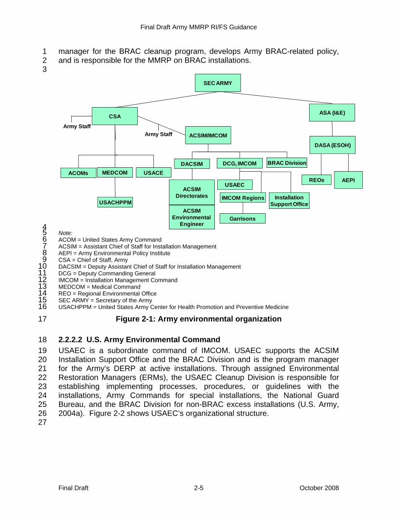
manager for the BRAC cleanup program, develops Army BRAC-related policy, 1 and is responsible for the MMRP on BRAC installations. 2 3
4 Note: 5 ACOM = United States Army Command 6 ACSIM = Assistant Chief of Staff for Installation Management 7 AEPI = Army Environmental Policy Institute 8 CSA = Chief of Staff, Army 9 DACSIM = Deputy Assistant Chief of Staff for Installation Management 10 DCG = Deputy Commanding General 11 IMCOM = Installation Management Command 12 MEDCOM = Medical Command 13 REO = Regional Environmental Office 14 SEC ARMY = Secretary of the Army 15 USACHPPM = United States Army Center for Health Promotion and Preventive Medicine 16
Figure 2-1: Army environmental organization 17
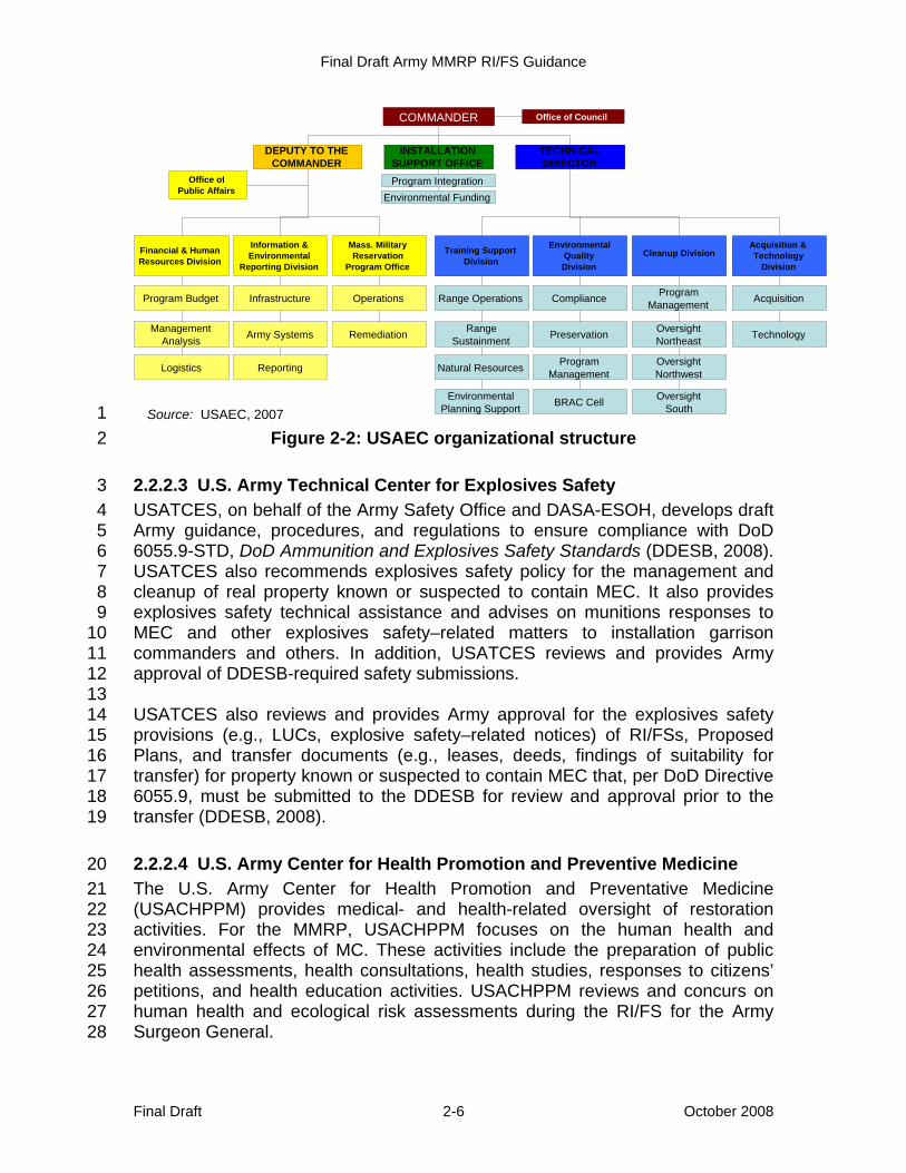
2.2.2.2 U.S. Army Environmental Command 18 USAEC is a subordinate command of IMCOM. USAEC supports the ACSIM 19 Installation Support Office and the BRAC Division and is the program manager 20 for the Army's DERP at active installations. Through assigned Environmental 21 Restoration Managers (ERMs), the USAEC Cleanup Division is responsible for 22 establishing implementing processes, procedures, or guidelines with the 23 installations, Army Commands for special installations, the National Guard 24 Bureau, and the BRAC Division for non-BRAC excess installations (U.S. Army, 25 2004a). Figure 2-2 shows USAEC’s organizational structure. 26 27
CSA
ACSIM/IMCOM
DASA (ESOH)
ASA (I&E)
SEC ARMY
ACSIMEnvironmental
Engineer
ACSIMDirectorates
DCG, IMCOM
USACHPPM
REOsUSAEC
DACSIMUSACEMEDCOMACOMs
AEPI
Army StaffArmy Staff
BRAC Division
InstallationSupport Office
Garrisons
IMCOM Regions
Final Draft Army MMRP RI/FS Guidance
Final Draft 2-6 October 2008
1 Figure 2-2: USAEC organizational structure 2
2.2.2.3 U.S. Army Technical Center for Explosives Safety 3 USATCES, on behalf of the Army Safety Office and DASA-ESOH, develops draft 4 Army guidance, procedures, and regulations to ensure compliance with DoD 5 6055.9-STD, DoD Ammunition and Explosives Safety Standards (DDESB, 2008). 6 USATCES also recommends explosives safety policy for the management and 7 cleanup of real property known or suspected to contain MEC. It also provides 8 explosives safety technical assistance and advises on munitions responses to 9 MEC and other explosives safety–related matters to installation garrison 10 commanders and others. In addition, USATCES reviews and provides Army 11 approval of DDESB-required safety submissions. 12 13 USATCES also reviews and provides Army approval for the explosives safety 14 provisions (e.g., LUCs, explosive safety–related notices) of RI/FSs, Proposed 15 Plans, and transfer documents (e.g., leases, deeds, findings of suitability for 16 transfer) for property known or suspected to contain MEC that, per DoD Directive 17 6055.9, must be submitted to the DDESB for review and approval prior to the 18 transfer (DDESB, 2008). 19
2.2.2.4 U.S. Army Center for Health Promotion and Preventive Medicine 20 The U.S. Army Center for Health Promotion and Preventative Medicine 21 (USACHPPM) provides medical- and health-related oversight of restoration 22 activities. For the MMRP, USACHPPM focuses on the human health and 23 environmental effects of MC. These activities include the preparation of public 24 health assessments, health consultations, health studies, responses to citizens’ 25 petitions, and health education activities. USACHPPM reviews and concurs on 26 human health and ecological risk assessments during the RI/FS for the Army 27 Surgeon General. 28
COMMANDER Office of Council
DEPUTY TO THE COMMANDER
INSTALLATION SUPPORT OFFICE
TECHNICAL DIRECTOR
Office ofPublic Affairs
Financial & Human Resources Division
Information & Environmental
Reporting Division
Mass. MilitaryReservation
Program Office
Training SupportDivision Cleanup Division
Environmental QualityDivision
Acquisition & Technology
Division
Program Budget
Management Analysis Logistics
Infrastructure
Army Systems
Reporting
Operations
Remediation
Range Operations
Range Sustainment
Natural Resources
Environmental Planning Support
Compliance
Preservation
Program Management
BRAC Cell
Program Management
Oversight Northeast
Oversight Northwest Oversight
South
Acquisition
Technology
Program IntegrationEnvironmental Funding
COMMANDER Office of Council
DEPUTY TO THE COMMANDER
INSTALLATION SUPPORT OFFICE
TECHNICAL DIRECTOR
Office ofPublic Affairs
Financial & Human Resources Division
Information & Environmental
Reporting Division
Mass. MilitaryReservation
Program Office
Training SupportDivision
Environmental QualityDivision
Acquisition & Technology
Division
Program Budget
Management Analysis Logistics
Infrastructure
Army Systems
Reporting
Operations
Remediation
Range Operations
Range Sustainment
Natural Resources
Environmental Planning Support
Compliance
Preservation
Program Management
BRAC Cell
Program Management
Oversight Northeast
Oversight Northwest Oversight
South
Acquisition
Technology
Program IntegrationEnvironmental Funding
Cleanup Division
Source: USAEC, 2007

Final Draft Army MMRP RI/FS Guidance
Final Draft 2-7 October 2008
2.2.2.5 U.S. Army Corps of Engineers and the Environmental and Munitions 1 Center of Expertise 2
USACE executes the FUDS program for DASA-ESOH, who is DoD's Executive 3 Agent for the program. USACE also routinely serves as the project manager for 4 munitions responses to MEC that are conducted at MRSs located on several 5 BRAC and active Army installations. 6 7 The Headquarters, USACE (HQUSACE) DoD Environmental Support Team is 8 responsible for budgeting, programming, and developing USACE guidance for 9 the FUDS program. The Regional Business Center and Project Management 10 District is responsible for FUDS project management and execution. Support for 11 MMRP remedial investigations and remedial action contracting is provided by the 12 five military design centers. Four of these design centers are military munitions 13 design centers located in the Baltimore, Omaha, and Huntsville Districts and in 14 the South Pacific Division Range Support Center. The fifth, the CWM Design 15 Center in Huntsville, Alabama, is the only design center authorized to perform 16 CWM response. Oversight of MMRP remediation is performed by one of 17 USACE’s 10 munitions remedial action districts: Baltimore, Omaha, Fort Worth, 18 Honolulu, Louisville, Savannah, Mobile, Los Angeles, Sacramento, and 19 Huntsville. A USACE district commander serves as installation commander for 20 each FUDS. In this capacity, district commanders execute environmental 21 restoration projects and fulfill associated responsibilities. The Environmental and 22 Munitions Center of Excellence (EM CX) provides technical support to 23 HQUSACE and design centers. 24
2.2.3 Installations 25 Active installations, Army Reserve, Army National Guard (ARNG), and special 26 installations, are responsible for execution of the MMRP. The garrison 27 commander (GC) for active installations and the Adjutant General for ARNG 28 installations are responsible for executing environmental programs for 29 installations under their control. 30 31 The GC and the Adjutant General for ARNG are responsible for tasking the 32 installation’s DERP Executors, reporting to their USAEC ERM, coordinating 33 regulatory and community involvement, and ensuring compliance with applicable 34 DoD and Army policies and federal and state laws and regulations (U.S. Army, 35 2004b). 36 37 As such, installations have the following responsibilities. 38
• MRS Project Management (Management of a Munitions Response) 39 – The Army uses the TPP process to plan the CERCLA response 40 process, including the RI/FS for an MRS. The TPP process, further 41 described in Section 3, provides a phased approach to planning that 42 produces the type and quality of results needed for site-specific decision-43 making. Using the TPP, installations: 44
Final Draft Army MMRP RI/FS Guidance
Final Draft 2-8 October 2008
° develop and submit work plans for regulatory review and 1 ° develop and submit DDESB-required safety submissions to 2
USATCES for review and Army endorsement and to be forwarded 3 to the DDESB for its review and approval. 4
• Regulatory Interface and Stakeholder Involvement – Installations: 5 ° establish a collaborative working relationship with environmental 6
regulators and safety officials to attempt to achieve mutual 7 agreement (consensus), particularly at critical decision points, and 8
° seek early and continuous stakeholder involvement throughout the 9 DERP process, ensuring that stakeholders, including property 10 owners, are offered opportunities as early as possible to participate 11 in the RI/FS process. 12
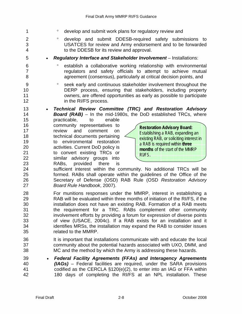
• Technical Review Committee (TRC) and Restoration Advisory 13 Board (RAB) – In the mid-1980s, the DoD established TRCs, where 14 practicable, to enable 15 community representatives to 16 review and comment on 17 technical documents pertaining 18 to environmental restoration 19 activities. Current DoD policy is 20 to convert existing TRCs or 21 similar advisory groups into 22 RABs, provided there is 23 sufficient interest within the community. No additional TRCs will be 24 formed. RABs shall operate within the guidelines of the Office of the 25 Secretary of Defense (OSD) RAB Rule (OSD Restoration Advisory 26 Board Rule Handbook, 2007). 27 For munitions responses under the MMRP, interest in establishing a 28 RAB will be evaluated within three months of initiation of the RI/FS, if the 29 installation does not have an existing RAB. Formation of a RAB meets 30 the requirement for a TRC. RABs complement other community 31 involvement efforts by providing a forum for expression of diverse points 32 of view (USACE, 2004c). If a RAB exists for an installation and it 33 identifies MRSs, the installation may expand the RAB to consider issues 34 related to the MMRP. 35 It is important that installations communicate with and educate the local 36 community about the potential hazards associated with UXO, DMM, and 37 MC and the method by which the Army is addressing these hazards. 38
• Federal Facility Agreements (FFAs) and Interagency Agreements 39 (IAGs) – Federal facilities are required, under the SARA provisions 40 codified as the CERCLA §120(e)(2), to enter into an IAG or FFA within 41 180 days of completing the RI/FS at an NPL installation. These 42
Restoration Advisory Board: Establishing a RAB, expanding an existing RAB, or soliciting interest in a RAB is required within three months of the start of the MMRP RI/FS.

Final Draft Army MMRP RI/FS Guidance
Final Draft 2-9 October 2008
agreements outline the roles and responsibilities of the DoD 1 components, the EPA and, frequently, the state in the cleanup process. 2
• Defense and State Memorandums of Agreement (DSMOAs) and 3 Cooperative Agreements (CAs) – The DSMOA/CA program funds 4 state environmental regulatory agencies for technical services provided 5 in support of the Army DERP. The goals of the DSMOA/CA program are 6 to expedite the cleanup process, to comply with state regulations, and to 7 improve coordination and cooperation between the DoD and 8 state/territorial regulatory communities. The Army is the lead agent for 9 the DSMOA/CA program, and USACE provides day-to-day 10 management of the DSMOA/CA program. 11
2.2.4 Regulatory Agencies Jurisdiction Overview 12 The Army coordinates with regulatory agencies and local Native American or 13 Native Alaskan tribal governments with jurisdiction, as stakeholders. Records of 14 these notifications are placed in the Administrative Record and Information 15 Repository for the MRS. 16
2.2.4.1 U.S. Environmental Protection Agency 17 The EPA develops and enforces regulations that implement environmental laws 18 enacted by the Congress. The EPA provides its own RPMs to oversee munitions 19 responses at DoD installations on the NPL. The EPA RPM’s primary 20 responsibilities are to ensure statutory compliance with federal environmental 21 laws governing CERCLA cleanups and to provide assistance to the DoD in its 22 MMRP efforts. The EPA and the DoD seek to operate under the partnering 23 concept. This concept facilitates open communication and information sharing 24 among EPA, state, and federal facilities. 25 26 Although the DoD is the lead agent at DoD installations, the EPA plays a key role 27 as a consultant in the remedial decision-making process at NPL installations. The 28 EPA is the lead regulator for NPL installations and a Base Closure Team (BCT) 29 member for BRAC installations. The EPA is the signatory agency and is asked to 30 concur with FFAs and Records of Decision (RODs) for NPL installations. 31 Ultimately, if the DoD and the EPA cannot agree on the remedy for an NPL site 32 and dispute resolution fails, the EPA has the right to select the remedy. 33 Therefore, it is important for the DoD to work together with the EPA throughout 34 the CERCLA response process. 35
2.2.4.2 State Regulatory Agencies 36 Federal facilities should coordinate response activities with federal, state, and 37 local authorities to implement CERCLA and NCP requirements for NPL sites. 38 CERCLA requires the DoD to ensure the EPA and appropriate state and local 39 authorities have adequate opportunity to participate in the planning and selection 40 of remedial actions. Although state regulatory agencies may sign FFAs, RODs, 41
Final Draft Army MMRP RI/FS Guidance
Final Draft 2-10 October 2008
and remedial Decision Documents (DDs), their signature is not required for 1 RODs and DDs at NPL sites. Nevertheless, they should be afforded an 2 opportunity to review such documents. The state normally serves as the lead 3 regulator for NPL installations and is a member of the BCT at BRAC installations. 4 5 States also have a role in defining applicable or relevant and appropriate 6 requirement (ARARs) for both NPL and non-NPL sites. CERCLA Section 121(d) 7 requires that, with some exceptions, federal facility remedial actions shall comply 8 with state laws if they are determined to be applicable or relevant and 9 appropriate in the RI process. CERCLA specifies that state laws “concerning 10 removal and remedial actions, including state laws regarding enforcement, shall 11 apply to removal and remedial actions at facilities owned or operated by [the 12 federal government] when such facilities are not included on the NPL” (42 U.S.C. 13 9620(a)(4)(2001)). 14 15 In some cases, munitions responses to MEC at an MRS can be addressed under 16 the RCRA Corrective Action Program or the Army may agree with RCRA 17 regulators to address RCRA Corrective Action sites as part of an ongoing 18 CERCLA response. The RCRA Corrective Action Program also requires that 19 active and BRAC installations conduct investigations and cleanup actions as 20 necessary. RCRA Corrective Action is not normally undertaken at FUDS 21 because the DoD is neither the owner nor operator at the property. Personnel 22 within state cleanup programs are typically the lead regulators for overseeing 23 corrective actions when the EPA has authorized the State Corrective Action 24 Program or an EPA Regional Office has entered into a work sharing agreement 25 with a state program. 26 27 It is critical that RPMs understand the statutory requirements as specified in 28 CERCLA and RCRA regarding state regulatory agency involvement in federal 29 facility remedial actions. State regulatory agencies may participate at varying 30 levels, including information review, project consultation, and remedial decision-31 making. It is beneficial to have open and honest communications with regulatory 32 agencies regarding federal facility cleanup activities. If there is any doubt about 33 the required level of participation, RPMs are advised to consult Army Program 34 Management and/or Army environmental counsel. 35
2.2.5 Department of Defense and Regulatory Partnerships 36 The DoD relies on partnerships with state and federal agencies to facilitate 37 planning and implementation of the DERP by providing the insight necessary to 38 efficiently execute restoration requirements and expedite the cleanup process. 39 These agreements include IAGs, FFAs, DSMOAs, and CAs. The DoD uses IAGs 40 and FFAs to involve the EPA and states in the environmental restoration process 41 by detailing the agencies’ roles at an installation. DSMOAs are agreements 42 between the DoD and the state specifying that the DoD will reimburse the state 43 for specific services the state will provide in support of DERP activities at DoD 44 installations. After signing a DSMOA with the DoD, a state may obtain a CA. CAs 45

Final Draft Army MMRP RI/FS Guidance
Final Draft 2-11 October 2008
are agreements detailing the work plan and funding for DERP activities at DoD 1 installations. 2

Final Draft Army MMRP RI/FS Guidance
Final Draft October 2008 3-1
3 Management of a Remedial Investigation / Feasibility 1 Study during a Munitions Response 2
Management of an RI/FS requires a collaborative working relationship with 3 regulators, stakeholder involvement, teamwork, and diligent planning to ensure 4 the collection of site-specific data needed to design an effective munitions 5 response, avoid the collection of unneeded data, and manage uncertainty. 6 7 USACE’s TPP process, which mirrors the EPA's Systematic Planning and is 8 widely accepted by Army installations, is the Army’s recommended planning 9 framework for use during the RI/FS. 10 11 Using the TPP process, the MR Project Team will: 12
• develop a problem statement; 13 • outline the available alternatives; 14 • determine the basic and optimum data needs while managing 15
uncertainty; and 16 • focus on the collection of the site-specific data needed to determine the 17
appropriate remedial alternative instead of attempting to resolve all 18 uncertainty. 19
20 The following sections discuss the general management of an RI/FS, including 21 identifying and managing MRAs and MRSs, implementing the TPP process, and 22 managing uncertainty during a munitions response. 23
3.1 Management of Munitions Response Areas and Munitions 24 Response Sites 25
During development of the Munitions Response Site Prioritization Protocol 26 (MRSPP) (32 CFR Part 179, 2005), the DoD developed two new terms, MRA 27 and MRS. An MRA is any area on a defense site that is known or suspected to 28 contain UXO, DMM, or MC. An MRA is composed of one or more MRSs. If an 29 MRA contains multiple MRSs, the sum total of the MRS acreages must equal the 30 MRA acreage. All MRSs are subject to the MRSPP. After an investigation, an 31 MRS may require a munitions response or NFA. Every MRA includes at least 32 one MRS, but may include multiple MRSs. If an MRA contains only one MRS, the 33 acreage of the MRS must equal that of the MRA. Every acre within an MRA is 34 part of an MRS and is subject to the MRSPP. 35 36 Because an MRA is often a large geographic area that may encompass an entire 37 former military range with thousands of acres, the MR Project Team may, after 38 development of a conceptual site model (CSM) for the installation or MRA, 39 subdivide an MRA into one or more MRSs. Understanding the munitions-related 40 activities that occurred at different areas within the MRA provides a better 41
Final Draft Army MMRP RI/FS Guidance
Final Draft October 2008 3-2
understanding of how each area was used. Because an MRS's use greatly 1 impacts the munitions response requirements, particularly when addressing 2 MEC, different response actions (e.g., surface removal, subsurface removal, no 3 removal, LUCs) may be appropriate for different portions of an MRA. This would 4 allow for subdivision to MRSs. Management of MRAs and MRSs is similar to the 5 management of operable units and exposure areas during a Hazardous Toxic 6 Radioactive Waste (HTRW) RI/FS. 7 8 Figure 3-1 depicts the relationship between an MRA and an MRS at a typical 9 installation. In Figure 3-1, the green area represents an operational range and, 10 therefore, is excluded from the MMRP. Of the remaining installation areas 11 potentially subject to the MMRP, only those areas known or suspected to contain 12 UXO, DMM, or MC should be considered as an MRA. In Figure 3-1, only MRA 1 13 and MRA 2 (colored orange) are known or suspected to contain UXO, DMM, or 14 MC. Please note that MRA 1 has been further delineated into two discrete MRSs 15 (MRS 1A and MRS 1B), while MRA 2 is composed of only one MRS (MRS 2). All 16 three MRSs (1A, 1B, and 2) require a munitions response. 17 18 This management approach ensures every acre of an MRA is addressed under 19 the MMRP. Subdivision of an MRA into multiple MRSs can be very useful for 20 managing a complex MRA. As previously mentioned, MRSs typically are based 21 on munitions-related activity that occurred at a given area and may include a 22 related group of exposure pathways, involving common receptors, that can easily 23 be presented in the preliminary CSM. Additionally, overlapping temporal and 24 spatial impact areas or ranges can be combined into one MRS. By subdividing 25 an MRA into multiple MRSs, the MR Project Team can focus the design of 26 munitions response activities on those needed to allow the property’s safe use 27 and accelerate an MRS’s closeout. 28 29

Final Draft Army MMRP RI/FS Guidance
Final Draft October 2008 3-3
1 Figure 3-1: Relationship between MRA and MRS 2
3
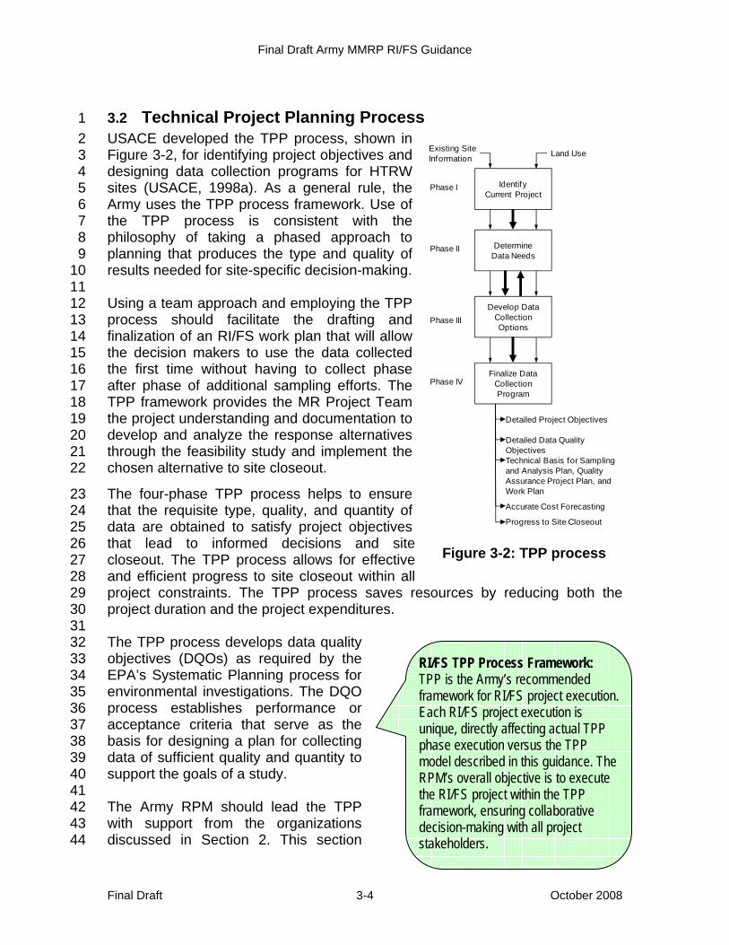
Final Draft Army MMRP RI/FS Guidance
Final Draft October 2008 3-4
3.2 Technical Project Planning Process 1 USACE developed the TPP process, shown in 2 Figure 3-2, for identifying project objectives and 3 designing data collection programs for HTRW 4 sites (USACE, 1998a). As a general rule, the 5 Army uses the TPP process framework. Use of 6 the TPP process is consistent with the 7 philosophy of taking a phased approach to 8 planning that produces the type and quality of 9 results needed for site-specific decision-making. 10 11 Using a team approach and employing the TPP 12 process should facilitate the drafting and 13 finalization of an RI/FS work plan that will allow 14 the decision makers to use the data collected 15 the first time without having to collect phase 16 after phase of additional sampling efforts. The 17 TPP framework provides the MR Project Team 18 the project understanding and documentation to 19 develop and analyze the response alternatives 20 through the feasibility study and implement the 21 chosen alternative to site closeout. 22
The four-phase TPP process helps to ensure 23 that the requisite type, quality, and quantity of 24 data are obtained to satisfy project objectives 25 that lead to informed decisions and site 26 closeout. The TPP process allows for effective 27 and efficient progress to site closeout within all 28 project constraints. The TPP process saves resources by reducing both the 29 project duration and the project expenditures. 30 31 The TPP process develops data quality 32 objectives (DQOs) as required by the 33 EPA’s Systematic Planning process for 34 environmental investigations. The DQO 35 process establishes performance or 36 acceptance criteria that serve as the 37 basis for designing a plan for collecting 38 data of sufficient quality and quantity to 39 support the goals of a study. 40 41 The Army RPM should lead the TPP 42 with support from the organizations 43 discussed in Section 2. This section 44
Figure 3-2: TPP process
IdentifyCurrent Project
DetermineData Needs
Develop Data Collection Options
Finalize Data Collection Program
Existing Site Information Land Use
Phase I
Phase II
Phase III
Phase IV
Detailed Project Objectives
Detailed Data Quality ObjectivesTechnical Basis for Sampling and Analysis Plan, Quality Assurance Project Plan, and Work Plan
Accurate Cost Forecasting
Progress to Site Closeout
RI/FS TPP Process Framework: TPP is the Army’s recommended framework for RI/FS project execution. Each RI/FS project execution is unique, directly affecting actual TPP phase execution versus the TPP model described in this guidance. The RPM’s overall objective is to execute the RI/FS project within the TPP framework, ensuring collaborative decision-making with all project stakeholders.
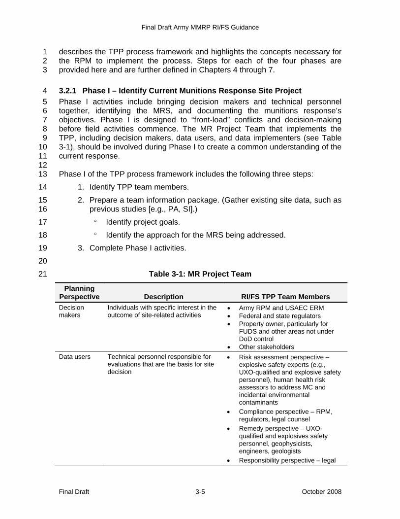
Final Draft Army MMRP RI/FS Guidance
Final Draft October 2008 3-5
describes the TPP process framework and highlights the concepts necessary for 1 the RPM to implement the process. Steps for each of the four phases are 2 provided here and are further defined in Chapters 4 through 7. 3
3.2.1 Phase I – Identify Current Munitions Response Site Project 4 Phase I activities include bringing decision makers and technical personnel 5 together, identifying the MRS, and documenting the munitions response’s 6 objectives. Phase I is designed to “front-load” conflicts and decision-making 7 before field activities commence. The MR Project Team that implements the 8 TPP, including decision makers, data users, and data implementers (see Table 9 3-1), should be involved during Phase I to create a common understanding of the 10 current response. 11 12 Phase I of the TPP process framework includes the following three steps: 13
1. Identify TPP team members. 14 2. Prepare a team information package. (Gather existing site data, such as 15
previous studies [e.g., PA, SI].) 16 ° Identify project goals. 17 ° Identify the approach for the MRS being addressed. 18
3. Complete Phase I activities. 19 20
Table 3-1: MR Project Team 21
Planning Perspective Description RI/FS TPP Team Members Decision makers
Individuals with specific interest in the outcome of site-related activities
• Army RPM and USAEC ERM • Federal and state regulators • Property owner, particularly for
FUDS and other areas not under DoD control
• Other stakeholders Data users Technical personnel responsible for
evaluations that are the basis for site decision
• Risk assessment perspective – explosive safety experts (e.g., UXO-qualified and explosive safety personnel), human health risk assessors to address MC and incidental environmental contaminants
• Compliance perspective – RPM, regulators, legal counsel
• Remedy perspective – UXO-qualified and explosives safety personnel, geophysicists, engineers, geologists
• Responsibility perspective – legal
Final Draft Army MMRP RI/FS Guidance
Final Draft October 2008 3-6
Planning Perspective Description RI/FS TPP Team Members
counsel (as appropriate)
Data implementers
Technical personnel responsible for identifying data collection methods suitable for satisfying the users’ data needs
• UXO-qualified personnel • Field team leaders
1 The outcome of Phase I is a Memorandum for Record (MFR) documenting the 2 MR Project Team’s findings and decisions during Phase I. Section 4.1 further 3 describes the information collection for Phase I, and Appendix D provides 4 example Phase I TPP worksheets. 5
3.2.2 Phase II – Determine Data Needs 6 Phase II activities involve an evaluation to determine if additional data are 7 needed to satisfy the MRS-specific munitions response objectives. It is critical to 8 document the data needed for the decision about required munitions response 9 activities and to tie those requirements directly to specific objectives. It is equally 10 important to avoid collecting unneeded information. These data needs are used 11 in Phase IV to create appropriate DQOs for the munitions response. 12 13 Phase II of the TPP process includes the following three steps: 14
1. Review Phase I MFR. 15 2. Determine Phase II information. 16
° Establish data users' roles (risk and hazard, compliance, remedy, 17 and responsibility). 18
° Evaluate use of existing data. 19 ° Define data needs by data user role. 20 ° Evaluate the relevance of the data need to the current project 21
objectives (basic, optimum, and excessive data needs). 22 ° Determine data collection approaches. 23
3. Complete Phase II activities. 24 25 When developing data requirements, it is helpful to determine whether the 26 desired data will support decisions about the munitions response activities 27 needed to allow the MRS's safe use for its intended purpose. Categorizing the 28 intended data needs as basic, optimum, and excessive is a powerful way to 29 prioritize collection efforts to meet the munitions response’s objectives developed 30 in Phase I and avoid collecting unnecessary data. Basic data provide information 31 to select from among response alternatives and are required to complete the 32 current executable stage. Optimum data help refine the cost of each response 33 alternative and scope the response with the lowest implementation risk. Optimum 34
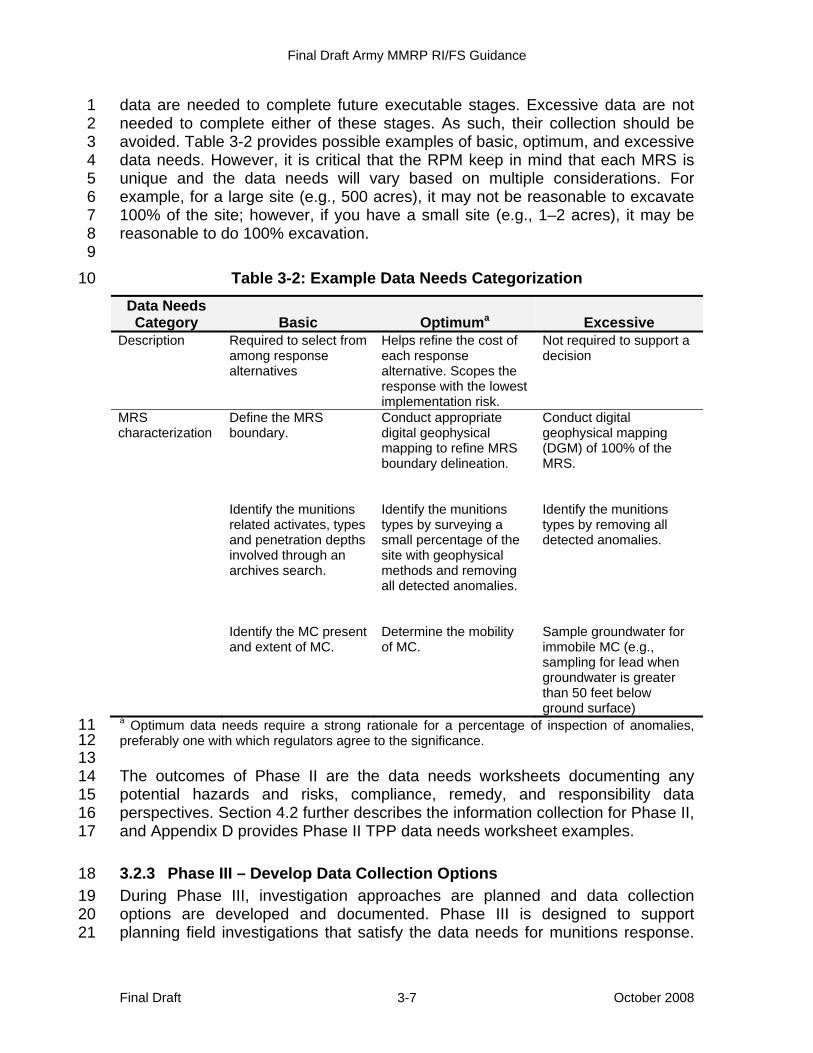
Final Draft Army MMRP RI/FS Guidance
Final Draft October 2008 3-7
data are needed to complete future executable stages. Excessive data are not 1 needed to complete either of these stages. As such, their collection should be 2 avoided. Table 3-2 provides possible examples of basic, optimum, and excessive 3 data needs. However, it is critical that the RPM keep in mind that each MRS is 4 unique and the data needs will vary based on multiple considerations. For 5 example, for a large site (e.g., 500 acres), it may not be reasonable to excavate 6 100% of the site; however, if you have a small site (e.g., 1–2 acres), it may be 7 reasonable to do 100% excavation. 8 9
Table 3-2: Example Data Needs Categorization 10
Data Needs Category Basic Optimuma Excessive
Description Required to select from among response alternatives
Helps refine the cost of each response alternative. Scopes the response with the lowest implementation risk.
Not required to support a decision
MRS characterization
Define the MRS boundary. Identify the munitions related activates, types and penetration depths involved through an archives search. Identify the MC present and extent of MC.
Conduct appropriate digital geophysical mapping to refine MRS boundary delineation. Identify the munitions types by surveying a small percentage of the site with geophysical methods and removing all detected anomalies. Determine the mobility of MC.
Conduct digital geophysical mapping (DGM) of 100% of the MRS. Identify the munitions types by removing all detected anomalies. Sample groundwater for immobile MC (e.g., sampling for lead when groundwater is greater than 50 feet below ground surface)
a Optimum data needs require a strong rationale for a percentage of inspection of anomalies, 11 preferably one with which regulators agree to the significance. 12 13 The outcomes of Phase II are the data needs worksheets documenting any 14 potential hazards and risks, compliance, remedy, and responsibility data 15 perspectives. Section 4.2 further describes the information collection for Phase II, 16 and Appendix D provides Phase II TPP data needs worksheet examples. 17
3.2.3 Phase III – Develop Data Collection Options 18 During Phase III, investigation approaches are planned and data collection 19 options are developed and documented. Phase III is designed to support 20 planning field investigations that satisfy the data needs for munitions response. 21
Final Draft Army MMRP RI/FS Guidance
Final Draft October 2008 3-8
Data implementers and data users are the primary MR Project Team members 1 needed to complete Phase III. Phase III includes three steps: 2
1. Review Phase I MFR and Phase II data needs. 3 2. Plan data collection options. 4 3. Document data collection options. 5
6 The outcomes of Phase III are the data collection options available to fill the data 7 needs identified in Phase II. Section 4.3 further describes the decisions for Phase 8 III, and Appendix D provides Phase III TPP data collection options worksheet 9 examples. 10
3.2.4 Phase IV – Finalize Data Collection Program 11 Phase IV activities challenge the MR Project Team to discuss data collection 12 options and finalize a data collection program that best meets the short- and 13 long-term goals for an MRS. Phase IV is designed to provide guidance for 14 documenting data collection programs with munitions response–specific DQO 15 statements for the MRS being addressed. DQOs and example DQO statements 16 are discussed in detail in Section 4.4.1. The decision makers should be involved 17 with the data users and data implementers in the selection of the data collection 18 program. The data implementers and data users should be responsible for 19 developing DQOs. Phase IV includes the following three steps: 20
1. Review Phase I MFR, Phase II data needs, and Phase III data collection 21 options. 22
2. Choose data collection options. 23 3. Finalize Phase IV. 24
° Document DQOs. 25 ° Prepare work plan (see Section 4.4.2). 26 ° Prepare fact sheets. 27
28 The following elements are compiled from the first three phases to create a DQO 29 statement: 30
• Data user perspective 31 • Munitions-related activities 32 • MC contaminant of interest or categories of munitions (UXO, DMM) by 33
type 34 • Media of interest 35 • Data collection method for UXO and DMM 36
° Determination of geophysical requirements (e.g., transects, 37 thresholds) 38
Final Draft Army MMRP RI/FS Guidance
Final Draft October 2008 3-9
° Selection of anomalies for investigation (discrimination) 1 ° Determination of number of anomalies that require investigation 2 ° Excavation of subsurface anomalies identified for investigation 3
• Data collection method for MC, to include the following: 4 ° Required sampling areas or locations and depths identified 5 ° Number of samples required 6 ° Reference concentration of interest or other performance criteria 7
identified 8 ° Sampling method 9 ° Sampling media 10 ° Analytical method 11
12 The MRS RPM and technical personnel must document the decisions made 13 during TPP efforts to contribute to the institutional knowledge of an MRS and for 14 presentation in required MRS-specific plans (sampling and analysis plans, work 15 plans). Documentation should, as appropriate, include specific DQOs, the RI/FS 16 work plan, and a fact sheet. Section 4.4 further describes the finalization in 17 Phase IV, and Appendix D provides DQO worksheet examples. 18
3.3 Managing Uncertainty 19 It is important to realize that the level of uncertainty about the distribution and 20 quantity of MEC present may be high for a munitions response prior to 21 conducting the RI. This is less true when only MC, even when in concentrations 22 high enough to pose an explosive hazard, are being addressed because the 23 extent of MC, like for other HTRWs, is easier to quantify (i.e., determine the 24 average residual concentration). However, the distribution and quantity of MC 25 should still be considered and managed in project planning. 26 27 Each MRS may have a different history with many unknown factors. For 28 example, the period of use may only be known to the nearest decade. The 29 number of soldiers trained and the types and quantity of munitions used (e.g., per 30 soldier, per training event) may only be calculated based on historical information 31 about the training requirements of the period or by using current training 32 requirements. UXO resulting from use may be estimated based on dud rates for 33 each munition, which may not exist, or an accepted dud rate for the period. Dud 34 rates vary among munitions items. The number of munitions disposed of by 35 burial (DMM) may only be determined from historical records (if any specific 36 information can be found) or by excavation. 37 38 Additional uncertainty is expected with the available MEC remedial alternatives. 39 Given the limitations in current detection technologies, some MEC might not be 40

Final Draft Army MMRP RI/FS Guidance
Final Draft October 2008 3-10
detected or removed during a munitions response. Although any residual risks 1 can be managed (e.g., by use of agreed upon LUCs, to include safety education, 2 5-year reviews, and construction support), residual explosive hazards might still 3 exist. The potential explosive hazards associated with any residual MEC present 4 at an MRS pose a different hazard (acute) than does low concentrations of MC or 5 other environmental contaminants. 6 7 The EPA understands the level of uncertainty during the RI/FS. According to the 8 EPA RI/FS guidance (1988): 9
The objective of the RI/FS process is not the unobtainable goal of 10 removing all uncertainty, but rather to gather information sufficient 11 to support an informed risk management decision regarding which 12 remedy appears to be most appropriate for a given MRS. 13
In addition to developing data needs based on specific project objectives and 14 data user perspectives through the TPP process, the MR Project Team should 15 seek to document any uncertainty identified during planning. 16 17 An uncertainty categorization matrix can be a useful tool in documenting and 18 achieving consensus on uncertainty management. A categorization matrix clearly 19 outlines the remaining uncertainties and the basis for selecting the management 20 technique applied. Uncertainty can be reduced through focused data collection or 21 mitigated through contingency plans. Table 3- provides the details of the factors 22 used in an uncertainty categorization matrix and examples of managing 23 uncertainty using this method. 24 25 Both examples provided in Table 3- refer to an MRA with two MRSs—a rifle 26 range from the 1960s and a grenade range from the 1940s located near each 27 other. In our examples, uncertainty arises during Phase I of the TPP because a 28 historical map brings into question the location of the grenade range and whether 29 the boundaries of the two ranges overlap. 30 31 In Example 1, the consequence of the grenade range boundary overlapping the 32 firing point portion of the rifle range is assessed. If an MRS that is suspected of 33 only containing MC (MRS 1) is found to contain UXO, the scope of the 34 investigation changes significantly, as do procedures for protecting on-site 35 workers. 36 37 In Example 2, the consequence of the safety fan from the rifle range overlapping 38 the grenade range is assessed. If an MRS that is suspected of containing MEC 39 (MRS 2) is also found to contain MC in the form of lead, the required response 40 may need to be changed to address any health hazards present. However, the 41 impact of such changes is less significant. The MR Project Team would need to 42 consider scoping additional MC sampling in the event that this uncertainty is 43 found to be true. 44
Final Draft Army MMRP RI/FS Guidance
Final Draft October 2008 3-11
3.4 Project Management Summary 1 Application of the TPP process is the recommended framework for the Army’s 2 MMRP RI/FS. The TPP process provides the Army’s project manager with a 3 method to achieve concurrence among the TPP participants. Section 4 describes 4 the various information and options applicable to the TPP process, and Appendix 5 D should be used as a resource for the TPP process. 6
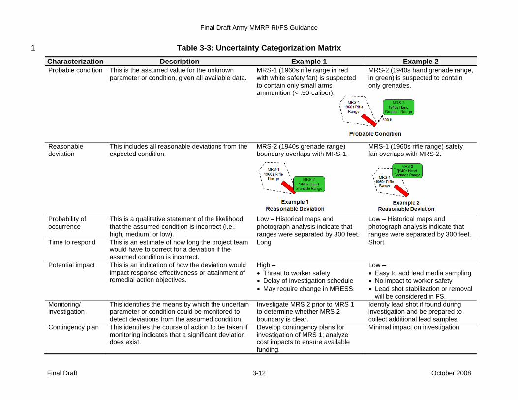
Final Draft Army MMRP RI/FS Guidance
Final Draft October 2008 3-12
Table 3-3: Uncertainty Categorization Matrix 1
Characterization Description Example 1 Example 2 Probable condition This is the assumed value for the unknown
parameter or condition, given all available data. MRS-1 (1960s rifle range in red with white safety fan) is suspected to contain only small arms ammunition (< .50-caliber).
MRS-2 (1940s hand grenade range, in green) is suspected to contain only grenades.
Reasonable deviation
This includes all reasonable deviations from the expected condition.
MRS-2 (1940s grenade range) boundary overlaps with MRS-1.
MRS-1 (1960s rifle range) safety fan overlaps with MRS-2.
Probability of occurrence
This is a qualitative statement of the likelihood that the assumed condition is incorrect (i.e., high, medium, or low).
Low – Historical maps and photograph analysis indicate that ranges were separated by 300 feet.
Low – Historical maps and photograph analysis indicate that ranges were separated by 300 feet.
Time to respond This is an estimate of how long the project team would have to correct for a deviation if the assumed condition is incorrect.
Long Short
Potential impact This is an indication of how the deviation would impact response effectiveness or attainment of remedial action objectives.
High – • Threat to worker safety • Delay of investigation schedule • May require change in MRESS.
Low – • Easy to add lead media sampling • No impact to worker safety • Lead shot stabilization or removal
will be considered in FS. Monitoring/ investigation
This identifies the means by which the uncertain parameter or condition could be monitored to detect deviations from the assumed condition.
Investigate MRS 2 prior to MRS 1 to determine whether MRS 2 boundary is clear.
Identify lead shot if found during investigation and be prepared to collect additional lead samples.
Contingency plan This identifies the course of action to be taken if monitoring indicates that a significant deviation does exist.
Develop contingency plans for investigation of MRS 1; analyze cost impacts to ensure available funding.
Minimal impact on investigation

Final Draft Army MMRP RI/FS Guidance
Final Draft October 2008 4-1
4 Scoping the Remedial Investigation / Feasibility 1 Study 2
During the scoping stage, the TPP process guides collection of existing data and 3 other available information to develop the RI/FS work plan. The work plan 4 describes the tasks required to conduct the RI/FS. The activities conducted 5 during the scoping step of the RI/FS process are shown in Figure 4-1 and 6 described in the following sections. 7 8
9 10
Figure 4-1: Scoping the RI/FS 11 12
Collect/Evaluate Existing Data to• Update CSM to identify data needs• Define land use - past, current, and future
Is Limited Field
Investigation Needed to
Plan?
Initiate Discussion of Federal/State
ARARsGeneral Response Action/Remedial Action Objectives• Identify likely alternatives based on land use• Identify need for interim/ treatability studies Preliminary
Identification of Action-Specific
ARARsIdentify Data Needs for Evaluation of Alternatives
Identify Data Quality Objectives• Site Characterization• Hazard / Risk Assessment• Interim / Treatability Studies
Conduct Geophysical
Prove Out (GPO)Describe Data Analysis Methods
and RI/FS Tasks
Prepare RI/FS Work Plan• Prepare Accident Prevention Plan/Site Safety and Health Plan (APP/SSHP)• Prepare Sampling and Analysis Plan•Prepare Quality Assurance Program Plan (QAPP)
Plan Limited Studies
Conduct Limited Studies
Collect Community Relations Data• Conduct Community Interviews
Identify Community Relations Issues
Develop Public Involvement Techniques
Prepare Community Relations Plan
Site CharacterizationDevelopment of
Alternatives
Yes
No
PrepareESP / CSP
Develop Site Characterization Strategies, Safety and Health Protocols
TPP Phase ITPP Phase IITPP Phase III & IVTPP Phase IV
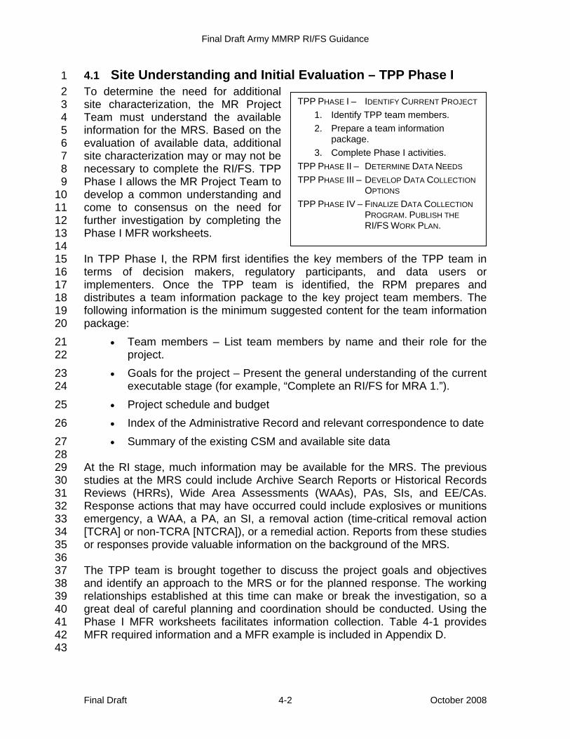
Final Draft Army MMRP RI/FS Guidance
Final Draft October 2008 4-2
4.1 Site Understanding and Initial Evaluation – TPP Phase I 1 To determine the need for additional 2 site characterization, the MR Project 3 Team must understand the available 4 information for the MRS. Based on the 5 evaluation of available data, additional 6 site characterization may or may not be 7 necessary to complete the RI/FS. TPP 8 Phase I allows the MR Project Team to 9 develop a common understanding and 10 come to consensus on the need for 11 further investigation by completing the 12 Phase I MFR worksheets. 13 14 In TPP Phase I, the RPM first identifies the key members of the TPP team in 15 terms of decision makers, regulatory participants, and data users or 16 implementers. Once the TPP team is identified, the RPM prepares and 17 distributes a team information package to the key project team members. The 18 following information is the minimum suggested content for the team information 19 package: 20
• Team members – List team members by name and their role for the 21 project. 22
• Goals for the project – Present the general understanding of the current 23 executable stage (for example, “Complete an RI/FS for MRA 1.”). 24
• Project schedule and budget 25 • Index of the Administrative Record and relevant correspondence to date 26 • Summary of the existing CSM and available site data 27
28 At the RI stage, much information may be available for the MRS. The previous 29 studies at the MRS could include Archive Search Reports or Historical Records 30 Reviews (HRRs), Wide Area Assessments (WAAs), PAs, SIs, and EE/CAs. 31 Response actions that may have occurred could include explosives or munitions 32 emergency, a WAA, a PA, an SI, a removal action (time-critical removal action 33 [TCRA] or non-TCRA [NTCRA]), or a remedial action. Reports from these studies 34 or responses provide valuable information on the background of the MRS. 35 36 The TPP team is brought together to discuss the project goals and objectives 37 and identify an approach to the MRS or for the planned response. The working 38 relationships established at this time can make or break the investigation, so a 39 great deal of careful planning and coordination should be conducted. Using the 40 Phase I MFR worksheets facilitates information collection. Table 4-1 provides 41 MFR required information and a MFR example is included in Appendix D. 42 43
TPP PHASE I – IDENTIFY CURRENT PROJECT 1. Identify TPP team members. 2. Prepare a team information
package. 3. Complete Phase I activities.
TPP PHASE II – DETERMINE DATA NEEDS TPP PHASE III – DEVELOP DATA COLLECTION
OPTIONS TPP PHASE IV – FINALIZE DATA COLLECTION
PROGRAM. PUBLISH THE RI/FS WORK PLAN.
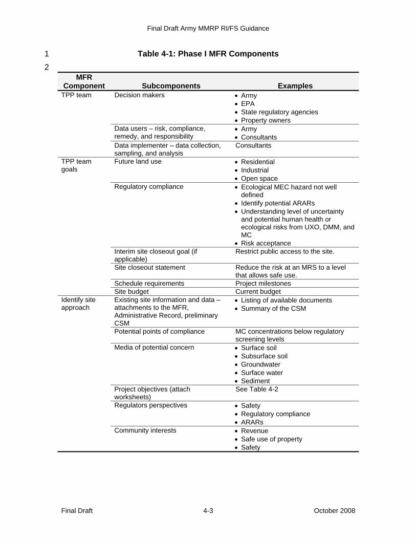
Final Draft Army MMRP RI/FS Guidance
Final Draft October 2008 4-3
Table 4-1: Phase I MFR Components 1 2
MFR Component Subcomponents Examples
TPP team Decision makers • Army • EPA • State regulatory agencies • Property owners
Data users – risk, compliance, remedy, and responsibility
• Army • Consultants
Data implementer – data collection, sampling, and analysis
Consultants
TPP team goals
Future land use • Residential • Industrial • Open space
Regulatory compliance • Ecological MEC hazard not well defined
• Identify potential ARARs • Understanding level of uncertainty
and potential human health or ecological risks from UXO, DMM, and MC
• Risk acceptance Interim site closeout goal (if applicable)
Restrict public access to the site.
Site closeout statement Reduce the risk at an MRS to a level that allows safe use.
Schedule requirements Project milestones Site budget Current budget
Identify site approach
Existing site information and data – attachments to the MFR, Administrative Record, preliminary CSM
• Listing of available documents • Summary of the CSM
Potential points of compliance MC concentrations below regulatory screening levels
Media of potential concern • Surface soil • Subsurface soil • Groundwater • Surface water • Sediment
Project objectives (attach worksheets)
See Table 4-2
Regulators perspectives • Safety • Regulatory compliance • ARARs
Community interests • Revenue • Safe use of property • Safety
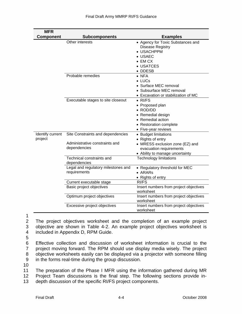
Final Draft Army MMRP RI/FS Guidance
Final Draft October 2008 4-4
MFR Component Subcomponents Examples
Other interests • Agency for Toxic Substances and Disease Registry
• USACHPPM • USAEC • EM CX • USATCES • DDESB
Probable remedies • NFA • LUCs • Surface MEC removal • Subsurface MEC removal • Excavation or stabilization of MC
Executable stages to site closeout • RI/FS • Proposed plan • ROD/DD • Remedial design • Remedial action • Restoration complete • Five-year reviews
Identify current project
Site Constraints and dependencies Administrative constraints and dependencies
• Budget limitations • Rights of entry • MRESS exclusion zone (EZ) and
evacuation requirements • Ability to manage uncertainty
Technical constraints and dependencies
Technology limitations
Legal and regulatory milestones and requirements
• Regulatory threshold for MEC • ARARs • Rights of entry
Current executable stage RI/FS Basic project objectives Insert numbers from project objectives
worksheet Optimum project objectives Insert numbers from project objectives
worksheet Excessive project objectives Insert numbers from project objectives
worksheet 1 The project objectives worksheet and the completion of an example project 2 objective are shown in Table 4-2. An example project objectives worksheet is 3 included in Appendix D, RPM Guide. 4 5 Effective collection and discussion of worksheet information is crucial to the 6 project moving forward. The RPM should use display media wisely. The project 7 objective worksheets easily can be displayed via a projector with someone filling 8 in the forms real-time during the group discussion. 9 10 The preparation of the Phase I MFR using the information gathered during MR 11 Project Team discussions is the final step. The following sections provide in-12 depth discussion of the specific RI/FS project components. 13
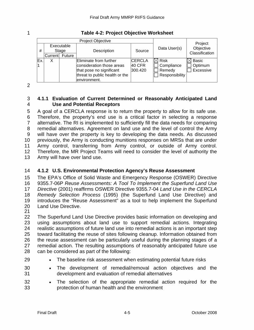
Final Draft Army MMRP RI/FS Guidance
Final Draft October 2008 4-5
Table 4-2: Project Objective Worksheet 1 Project Objective
Data User(s) Project
Objective Classification #
Executable Stage Description Source
Current Future Ex. 1
X Eliminate from further consideration those areas that pose no significant threat to public health or the environment.
CERCLA 40 CFR 300.420
Risk Compliance Remedy Responsibility
Basic Optimum Excessive
2
4.1.1 Evaluation of Current Determined or Reasonably Anticipated Land 3 Use and Potential Receptors 4
A goal of a CERCLA response is to return the property to allow for its safe use. 5 Therefore, the property’s end use is a critical factor in selecting a response 6 alternative. The RI is implemented to sufficiently fill the data needs for comparing 7 remedial alternatives. Agreement on land use and the level of control the Army 8 will have over the property is key to developing the data needs. As discussed 9 previously, the Army is conducting munitions responses on MRSs that are under 10 Army control, transferring from Army control, or outside of Army control. 11 Therefore, the MR Project Teams will need to consider the level of authority the 12 Army will have over land use. 13
4.1.2 U.S. Environmental Protection Agency’s Reuse Assessment 14 The EPA’s Office of Solid Waste and Emergency Response (OSWER) Directive 15 9355.7-06P Reuse Assessments: A Tool To Implement the Superfund Land Use 16 Directive (2001) reaffirms OSWER Directive 9355.7-04 Land Use in the CERCLA 17 Remedy Selection Process (1995) (the Superfund Land Use Directive) and 18 introduces the “Reuse Assessment” as a tool to help implement the Superfund 19 Land Use Directive. 20 21 The Superfund Land Use Directive provides basic information on developing and 22 using assumptions about land use to support remedial actions. Integrating 23 realistic assumptions of future land use into remedial actions is an important step 24 toward facilitating the reuse of sites following cleanup. Information obtained from 25 the reuse assessment can be particularly useful during the planning stages of a 26 remedial action. The resulting assumptions of reasonably anticipated future use 27 can be considered as part of the following: 28
• The baseline risk assessment when estimating potential future risks 29 • The development of remedial/removal action objectives and the 30
development and evaluation of remedial alternatives 31 • The selection of the appropriate remedial action required for the 32
protection of human health and the environment 33
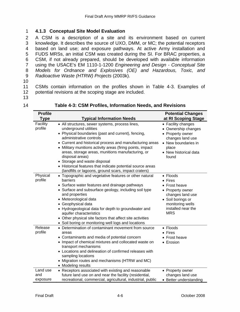
Final Draft Army MMRP RI/FS Guidance
Final Draft October 2008 4-6
4.1.3 Conceptual Site Model Evaluation 1 A CSM is a description of a site and its environment based on current 2 knowledge. It describes the source of UXO, DMM, or MC; the potential receptors 3 based on land use; and exposure pathways. At active Army installation and 4 FUDS MRSs, an initial CSM was created during the SI. For BRAC properties, a 5 CSM, if not already prepared, should be developed with available information 6 using the USACE's EM 1110-1-1200 Engineering and Design - Conceptual Site 7 Models for Ordnance and Explosives (OE) and Hazardous, Toxic, and 8 Radioactive Waste (HTRW) Projects (2003k). 9 10 CSMs contain information on the profiles shown in Table 4-3. Examples of 11 potential revisions at the scoping stage are included. 12 13
Table 4-3: CSM Profiles, Information Needs, and Revisions 14
Profile Type Typical Information Needs
Potential Changes at RI Scoping Stage
Facility profile
• All structures, sewer systems, process lines, underground utilities
• Physical boundaries (past and current), fencing, administrative controls
• Current and historical process and manufacturing areas • Military munitions activity areas (firing points, impact
areas, storage areas, munitions manufacturing, or disposal areas)
• Storage and waste disposal • Historical features that indicate potential source areas
(landfills or lagoons, ground scars, impact craters)
• Facility changes • Ownership changes • Property owner
changes land use • New boundaries in
place • New historical data
found
Physical profile
• Topographic and vegetative features or other natural barriers
• Surface water features and drainage pathways • Surface and subsurface geology, including soil type
and properties • Meteorological data • Geophysical data • Hydrogeological data for depth to groundwater and
aquifer characteristics • Other physical site factors that affect site activities • Soil boring or monitoring well logs and locations
• Floods • Fires • Frost heave • Property owner
changes land use • Soil borings or
monitoring wells installed near the MRS
Release profile
• Determination of contaminant movement from source areas
• Contaminants and media of potential concern • Impact of chemical mixtures and collocated waste on
transport mechanisms • Locations and delineation of confirmed releases with
sampling locations • Migration routes and mechanisms (HTRW and MC) • Modeling results
• Floods • Fires • Frost heave • Erosion
Land use and exposure
• Receptors associated with existing and reasonable future land use on and near the facility (residential, recreational, commercial, agricultural, industrial, public
• Property owner changes land use
• Better understanding

Final Draft Army MMRP RI/FS Guidance
Final Draft October 2008 4-7
Profile Type Typical Information Needs
Potential Changes at RI Scoping Stage
profile forest, etc.) • Zoning (applicable to transferred sites within the active
program, BRAC sites, and FUDS) • Types of existing or future activities at the facility,
including frequency and nature of activity (intrusive or nonintrusive)
• Beneficial resource determination (aquifer classification, natural resources, wetlands, cultural resources, etc.)
• Resource use locations (water supply wells; recreational swimming, boating, or fishing areas; hiking trails; grazing lands; historical burial grounds; etc.)
• Demographics, including subpopulation types and locations (schools, hospitals, day care centers, site workers, etc.)
of land use activities • Demographic
changes • New facilities in or
around MRS
Ecological profile
• Description of the property at the facility, including habitat type (wetland, forest, desert, pond, etc.)
• Primary use of the property and degree of disturbance, if any
• Identification of any ecological receptors in relation to habitat type (endangered or threatened species, migratory animals, fish, etc.)
• Relationship of Army releases of hazardous substances to potential habitat areas (locations, sampling data, migration pathways, etc.)
• Floods • Fires • Frost heave • Ecological studies
performed in surrounding areas
1 Graphical representations of the exposure pathway explain the completeness of 2 a given pathway. The exposure pathway between a source and a receptor for 3 UXO and DMM requires access to MEC and an activity (e.g., moving, touching) 4 allowing contact with these categories of MEC. Exposure pathways for MC 5 require an exposure medium (e.g., soil) and an exposure route (e.g., dermal 6 contact) with a release mechanism and a transport medium sometimes being 7 present. Examples of a CSM are provided in Figures 4-2 (wire frame) and 4-3 8 (three dimensional [3D]). 9 10 The CSM provides an organized approach to identifying data needs. Figure 4-2 11 and Figure 4-3 show complete, potentially complete, and incomplete pathways. 12 The data needs for an MRS depend on this evaluation. The pathways should be 13 considered as follows: 14
• Incomplete pathways: No risk or hazard is associated with the pathway. 15 No further data are required to confirm the pathway is incomplete. 16
• Potentially complete pathways: Data needs determine if pathway is 17 complete. If the pathway is determined to be incomplete, there is no risk 18 or hazard. If the pathway is determined to be complete, a potential risk 19 or hazard exists. 20
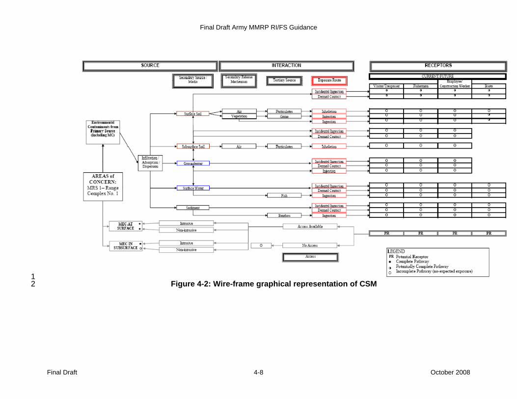
Final Draft Army MMRP RI/FS Guidance
Final Draft October 2008 4-8
1 Figure 4-2: Wire-frame graphical representation of CSM 2
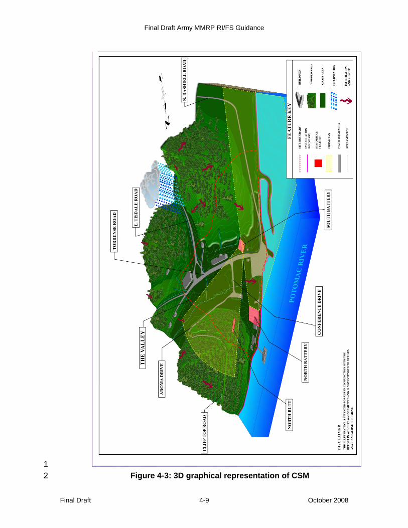
Final Draft Army MMRP RI/FS Guidance
Final Draft October 2008 4-9
1 Figure 4-3: 3D graphical representation of CSM2
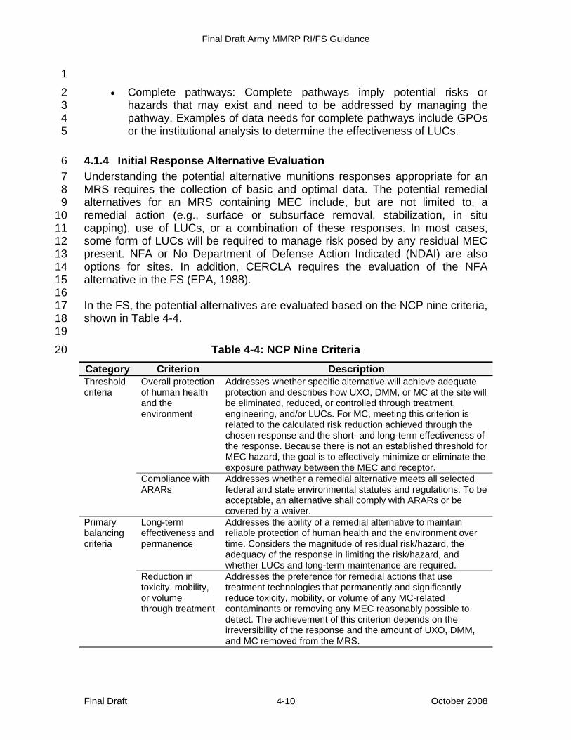
Final Draft Army MMRP RI/FS Guidance
Final Draft October 2008 4-10
1 • Complete pathways: Complete pathways imply potential risks or 2
hazards that may exist and need to be addressed by managing the 3 pathway. Examples of data needs for complete pathways include GPOs 4 or the institutional analysis to determine the effectiveness of LUCs. 5
4.1.4 Initial Response Alternative Evaluation 6 Understanding the potential alternative munitions responses appropriate for an 7 MRS requires the collection of basic and optimal data. The potential remedial 8 alternatives for an MRS containing MEC include, but are not limited to, a 9 remedial action (e.g., surface or subsurface removal, stabilization, in situ 10 capping), use of LUCs, or a combination of these responses. In most cases, 11 some form of LUCs will be required to manage risk posed by any residual MEC 12 present. NFA or No Department of Defense Action Indicated (NDAI) are also 13 options for sites. In addition, CERCLA requires the evaluation of the NFA 14 alternative in the FS (EPA, 1988). 15 16 In the FS, the potential alternatives are evaluated based on the NCP nine criteria, 17 shown in Table 4-4. 18 19
Table 4-4: NCP Nine Criteria 20
Category Criterion Description Threshold criteria
Overall protection of human health and the environment
Addresses whether specific alternative will achieve adequate protection and describes how UXO, DMM, or MC at the site will be eliminated, reduced, or controlled through treatment, engineering, and/or LUCs. For MC, meeting this criterion is related to the calculated risk reduction achieved through the chosen response and the short- and long-term effectiveness of the response. Because there is not an established threshold for MEC hazard, the goal is to effectively minimize or eliminate the exposure pathway between the MEC and receptor.
Compliance with ARARs
Addresses whether a remedial alternative meets all selected federal and state environmental statutes and regulations. To be acceptable, an alternative shall comply with ARARs or be covered by a waiver.
Primary balancing criteria
Long-term effectiveness and permanence
Addresses the ability of a remedial alternative to maintain reliable protection of human health and the environment over time. Considers the magnitude of residual risk/hazard, the adequacy of the response in limiting the risk/hazard, and whether LUCs and long-term maintenance are required.
Reduction in toxicity, mobility, or volume through treatment
Addresses the preference for remedial actions that use treatment technologies that permanently and significantly reduce toxicity, mobility, or volume of any MC-related contaminants or removing any MEC reasonably possible to detect. The achievement of this criterion depends on the irreversibility of the response and the amount of UXO, DMM, and MC removed from the MRS.
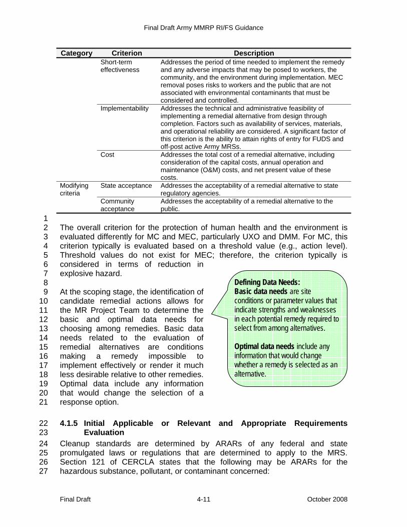
Final Draft Army MMRP RI/FS Guidance
Final Draft October 2008 4-11
Category Criterion Description Short-term effectiveness
Addresses the period of time needed to implement the remedy and any adverse impacts that may be posed to workers, the community, and the environment during implementation. MEC removal poses risks to workers and the public that are not associated with environmental contaminants that must be considered and controlled.
Implementability Addresses the technical and administrative feasibility of implementing a remedial alternative from design through completion. Factors such as availability of services, materials, and operational reliability are considered. A significant factor of this criterion is the ability to attain rights of entry for FUDS and off-post active Army MRSs.
Cost Addresses the total cost of a remedial alternative, including consideration of the capital costs, annual operation and maintenance (O&M) costs, and net present value of these costs.
Modifying criteria
State acceptance Addresses the acceptability of a remedial alternative to state regulatory agencies.
Community acceptance
Addresses the acceptability of a remedial alternative to the public.
1 The overall criterion for the protection of human health and the environment is 2 evaluated differently for MC and MEC, particularly UXO and DMM. For MC, this 3 criterion typically is evaluated based on a threshold value (e.g., action level). 4 Threshold values do not exist for MEC; therefore, the criterion typically is 5 considered in terms of reduction in 6 explosive hazard. 7 8 At the scoping stage, the identification of 9 candidate remedial actions allows for 10 the MR Project Team to determine the 11 basic and optimal data needs for 12 choosing among remedies. Basic data 13 needs related to the evaluation of 14 remedial alternatives are conditions 15 making a remedy impossible to 16 implement effectively or render it much 17 less desirable relative to other remedies. 18 Optimal data include any information 19 that would change the selection of a 20 response option. 21
4.1.5 Initial Applicable or Relevant and Appropriate Requirements 22 Evaluation 23
Cleanup standards are determined by ARARs of any federal and state 24 promulgated laws or regulations that are determined to apply to the MRS. 25 Section 121 of CERCLA states that the following may be ARARs for the 26 hazardous substance, pollutant, or contaminant concerned: 27
Defining Data Needs: Basic data needs are site conditions or parameter values that indicate strengths and weaknesses in each potential remedy required to select from among alternatives. Optimal data needs include any information that would change whether a remedy is selected as an alternative.
Final Draft Army MMRP RI/FS Guidance
Final Draft October 2008 4-12
• Any standard, requirement, criteria, or limitation promulgated under any 1 federal environmental law 2
• Any promulgated standard, requirement, criterion, or limitation under a 3 state environmental or facility siting law that is more stringent than any 4 federal standard, requirement, criterion, or limitation and that has been 5 identified to the Army by the state in a timely manner. 6
7 ARARs constitute only those 8 substantive requirements 9 promulgated in environmental or 10 facility citing laws. Administrative 11 requirements, such as permits and 12 procedural requirements, are not, by 13 definition, ARARs. Any questions 14 about ARARs that can be answered 15 by the investigation should be 16 included in the study (e.g., 17 endangered species—if no 18 threatened or endangered species 19 are found during the RI, threatened 20 and endangered species would not 21 be an applicable requirement). Because this is an initial evaluation, ARARs are 22 not defined during this stage but are fully defined during the FS. 23 24 Compliance with ARARs is a threshold criterion in remedy selection; therefore, 25 determining the ARARs and whether a remedy will comply with them is of critical 26 importance to the remedial action. The NCP states an applicable requirement is 27 one specifically addressing a hazardous substance, pollutant, contaminant, 28 remedial action, location, or other circumstances at a CERCLA site. If it is 29 determined that a requirement is not applicable to a specific release site, then the 30 requirement is examined to determine if it is relevant and appropriate to the 31 circumstances of the release. A remedy may also be both applicable and 32 relevant and appropriate. 33 34 To be considered requirements (TBCs) are nonpromulgated advisories (such as 35 reference doses or potency factors), criteria, and guidance issued by federal and 36 state governments. TBCs do not have the same status of ARARs; however, 37 Section 300.400 of the NCP specifies that TBCs may be identified, as 38 appropriate, to supplement ARARs where they do not exist or where it has been 39 determined that the ARARs are insufficient to ensure protection of human health 40 and the environment at that particular release (USAEC, 1998). 41
4.1.6 Preliminary Remediation Goals 42 In developing an RI/FS work plan, preliminary remediation goals (PRGs) for 43 UXO, DMM, and MC are identified to determine the effectiveness of remedial 44 actions. There are no established PRGs for MEC, particularly UXO and DMM. 45
ARAR Summary: The RPM should consult legal counsel, who should work closely with the EPA and the states to ensure each is notified of the requirements the others have determined to be applicable or relevant and appropriate and to ensure appropriate ARARs are identified and considered at critical steps in the remedial planning process (USAEC, 1998).

Final Draft Army MMRP RI/FS Guidance
Final Draft October 2008 4-13
Rather, the property's use and pathways for exposure to MEC drive the design of 1 the munitions response. In general, the remediation goals for MEC focus on 2 removing or limiting the exposure pathways. 3 4 For MRSs with MC or other incidental 5 contamination, medium-specific goals 6 are identified, providing a clear and 7 concise description of what the 8 remedial action should accomplish. 9 When establishing medium-specific 10 goals for MC, background 11 concentrations and whether the goals 12 are analytically achievable should be 13 taken into account. PRGs focus on protecting human health and the environment 14 while allowing for the variation in remedial alternatives—treatment, containment, 15 and removal. Discussion of MC PRGs with the TPP team members is important 16 in order to collect appropriate data. 17 18 The EPA published the Regional Screening Table developed by Oak Ridge 19 National Laboratory under an Interagency Agreement with the EPA. The new 20 screening tables, as well as the user's guide and "master" screening table, are 21 online at http://epa-prgs.ornl.gov/chemicals/. The online calculator can be used to 22 generate "site-specific" screening levels (http://epa-prgs.ornl.gov/cgi-23 bin/chemicals/csl_search). 24
4.2 Determining Data Needs – TPP Phase II 25 Evaluating existing site data, determining the data needed to make appropriate 26 and supportable decisions about the site, and identifying methods for collecting 27 that data are the components of the second phase in the TPP process. Phase II 28 can occur in conjunction with Phase I. As the current project is identified, data 29 needs may become apparent to the team. Otherwise, the data needs can be 30 developed following a more thorough review of the Phase I MFR either by 31 teleconference or through electronic communications. 32 33 One of the first actions during this phase is to review the Phase I MFR. The key 34 participants are the decision makers and the data users. If any corrections or 35 changes in project information are identified, the RPM should redistribute the 36 revised Phase I MFR to the team. The RPM should then determine the Phase II 37 TPP information required in the following manner. 38
• Establish data user’s roles. Data users in the TPP process are technical 39 and other personnel responsible for engineering, scientific, and legal 40 evaluations that are the basis for site decisions. The TPP process 41 identifies four data user perspectives—risk, compliance, remedy, and 42 responsibility. The majority of the Army’s MMRP RI/FS program does 43
TPP PHASE I – IDENTIFY CURRENT PROJECT TPP PHASE II – DETERMINE DATA NEEDS
1. Review Phase I MFR. 2. Determine Phase II TPP information. 3. Complete Phase II activities.
TPP PHASE III – DEVELOP DATA COLLECTION OPTIONS
TPP PHASE IV – FINALIZE DATA COLLECTION PROGRAM

Final Draft Army MMRP RI/FS Guidance
Final Draft October 2008 4-14
not have a responsibility data user because the Army is responsible for 1 the munitions response. 2
• Evaluate use of existing data. Existing data were gathered during Phase 3 I and included as part of the CSM. Before defining data needs for the 4 project, existing data usability evaluation occurs. Existing data may be 5 suitable for qualitative and quantitative uses. The team must be aware 6 that some existing data may be of an unacceptable quality for one use, 7 but of acceptable quality for another use. For example, a site 8 reconnaissance may be enough to indicate a removal action is required 9 in a given area; however, it may not provide enough information to 10 evaluate the costs of conducting the removal action. More data may be 11 required to develop accurate cost estimates for planning purposes. 12
• Define data needs. The team must identify specific data needs for 13 collection in order to support the potential decisions to be made. Data 14 needs are to be documented for each area of concern. The team 15 should: 16 ° consider the consequences of incorrect decisions or decision 17
errors; 18 ° consider how much data is required and for what the data will be 19
used; 20 ° consider data collection approaches, including field screening 21
approaches; 22 ° consider the cost of additional data collection in dollars and time; 23
and then 24 ° decide how data needs can be balanced within project cost and 25
schedule constraints. 26 27
The following are the four general data sets for characterizing an MRS and 28 analyzing potential remedial alternatives: 29 30 Physical nature of the site – the natural, 31 environmental, and cultural features and 32 resources of a site that may affect or be 33 affected by remedial alternatives requiring 34 the use, detection, recovery, or disposal of 35 UXO, DMM, or MC 36 37 Characterization of UXO, DMM, or MC – 38 the distribution and characteristics of UXO, 39 DMM, or MC at the site (e.g., ferrous or 40 nonferrous material) that will help 41 determine the applicability of remedial alternatives; the type of UXO, DMM or 42 MC, media concentration, MRS boundary, and any UXO, DMM, or MC present 43 that are needed to determine remedial alternatives 44
MRS Characterization: The RPM should consider the following four general data sets for MRS characterization and analyzing remedy alternatives: 1. Physical nature of the site 2. Characterization of DMM,
UXO and MC 3. Regulatory framework 4. Demographics and land use

Final Draft Army MMRP RI/FS Guidance
Final Draft October 2008 4-15
1 Regulatory framework – the laws, regulations, and guidance that affect the 2 remedial alternatives, to include NFA and the use, detection, recovery or 3 treatment, or disposal of any UXO, DMM or MC present at an MRS 4 5 Demographics and land use – the distribution, density, characteristics, and 6 changes of the human population and their influences on the way land is used at 7 the site (current and future land use is identified in TPP Phase I). Knowing the 8 property’s end use (existing, determined, or reasonably anticipated) is critical to 9 determining appropriate remedial alternatives. The property’s end use should be 10 identified as early in the process as possible to determine the appropriate DQOs 11 for site characterization. A full discussion of DQOs can be found in Section 4.4.1. 12
• Generally, only data needed to support potential decisions, project 13 objectives, and site closeout should be gathered. Each requirement 14 should be labeled as a basic data need, an optimal data need, or an 15 excessive data need. The following six basic questions may help the 16 team members determine the amount of data needed: 17 ° How much data do I need to 18
determine that an area warrants 19 NFA? 20
° How much data do I need to 21 determine that an area requires 22 an accelerated response—TCRA 23 or NTCRA? 24
° How much data do I need to 25 determine the potential hazards 26 posed by UXO, DMM, or MC and 27 the relative risk posed? 28
° How much data do I need to evaluate a response alternative and 29 develop a realistic cost estimate? 30
° How much data do I need to gain regulator and stakeholder 31 concurrence with potential decisions to be made? 32
° How much data do I need to develop a LUC plan? 33 34 The final step is documentation of the data needs. For MC, the worksheets 35 provided in Appendix D are used to document the risk, compliance, and remedy 36 data needs. For MEC data needs, a tabular or narrative format of each data need 37 and the required specifics is created. 38 39 Sections 4.2.1–4.2.5 provide in-depth discussion of additional project 40 components. The following types of MRSs are unique in the approach for the 41 RI/FS process. These MRSs require a different level of effort than a more 42 traditional MRS. 43
Emergency Response: The RPM should understand the emergency response is a different process for CERCLA. Please refer to the Guidance for Conducting Remedial Investigations and Feasibility Studies Under CERCLA (EPA, 1988).
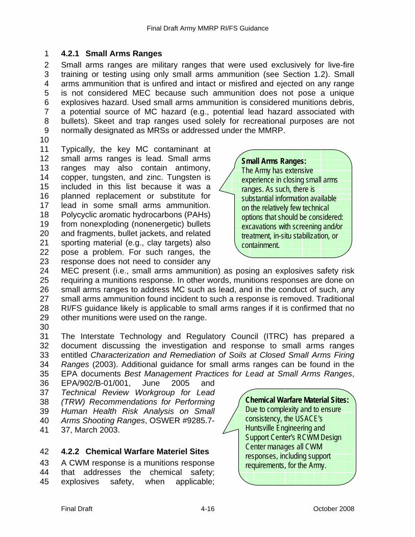
Final Draft Army MMRP RI/FS Guidance
Final Draft October 2008 4-16
4.2.1 Small Arms Ranges 1 Small arms ranges are military ranges that were used exclusively for live-fire 2 training or testing using only small arms ammunition (see Section 1.2). Small 3 arms ammunition that is unfired and intact or misfired and ejected on any range 4 is not considered MEC because such ammunition does not pose a unique 5 explosives hazard. Used small arms ammunition is considered munitions debris, 6 a potential source of MC hazard (e.g., potential lead hazard associated with 7 bullets). Skeet and trap ranges used solely for recreational purposes are not 8 normally designated as MRSs or addressed under the MMRP. 9 10 Typically, the key MC contaminant at 11 small arms ranges is lead. Small arms 12 ranges may also contain antimony, 13 copper, tungsten, and zinc. Tungsten is 14 included in this list because it was a 15 planned replacement or substitute for 16 lead in some small arms ammunition. 17 Polycyclic aromatic hydrocarbons (PAHs) 18 from nonexploding (nonenergetic) bullets 19 and fragments, bullet jackets, and related 20 sporting material (e.g., clay targets) also 21 pose a problem. For such ranges, the 22 response does not need to consider any 23 MEC present (i.e., small arms ammunition) as posing an explosives safety risk 24 requiring a munitions response. In other words, munitions responses are done on 25 small arms ranges to address MC such as lead, and in the conduct of such, any 26 small arms ammunition found incident to such a response is removed. Traditional 27 RI/FS guidance likely is applicable to small arms ranges if it is confirmed that no 28 other munitions were used on the range. 29 30 The Interstate Technology and Regulatory Council (ITRC) has prepared a 31 document discussing the investigation and response to small arms ranges 32 entitled Characterization and Remediation of Soils at Closed Small Arms Firing 33 Ranges (2003). Additional guidance for small arms ranges can be found in the 34 EPA documents Best Management Practices for Lead at Small Arms Ranges, 35 EPA/902/B-01/001, June 2005 and 36 Technical Review Workgroup for Lead 37 (TRW) Recommendations for Performing 38 Human Health Risk Analysis on Small 39 Arms Shooting Ranges, OSWER #9285.7-40 37, March 2003. 41
4.2.2 Chemical Warfare Materiel Sites 42 A CWM response is a munitions response 43 that addresses the chemical safety; 44 explosives safety, when applicable; 45
Small Arms Ranges: The Army has extensive experience in closing small arms ranges. As such, there is substantial information available on the relatively few technical options that should be considered: excavations with screening and/or treatment, in-situ stabilization, or containment.
Chemical Warfare Material Sites: Due to complexity and to ensure consistency, the USACE's Huntsville Engineering and Support Center's RCWM Design Center manages all CWM responses, including support requirements, for the Army.
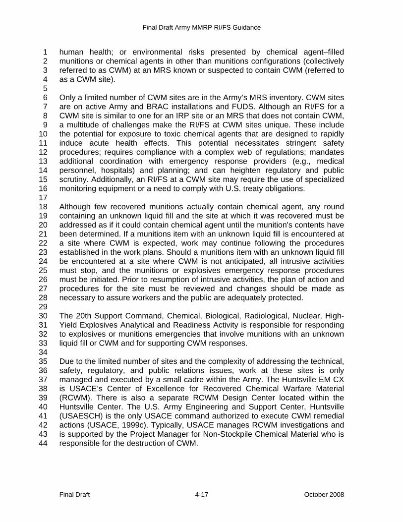
Final Draft Army MMRP RI/FS Guidance
Final Draft October 2008 4-17
human health; or environmental risks presented by chemical agent–filled 1 munitions or chemical agents in other than munitions configurations (collectively 2 referred to as CWM) at an MRS known or suspected to contain CWM (referred to 3 as a CWM site). 4 5 Only a limited number of CWM sites are in the Army’s MRS inventory. CWM sites 6 are on active Army and BRAC installations and FUDS. Although an RI/FS for a 7 CWM site is similar to one for an IRP site or an MRS that does not contain CWM, 8 a multitude of challenges make the RI/FS at CWM sites unique. These include 9 the potential for exposure to toxic chemical agents that are designed to rapidly 10 induce acute health effects. This potential necessitates stringent safety 11 procedures; requires compliance with a complex web of regulations; mandates 12 additional coordination with emergency response providers (e.g., medical 13 personnel, hospitals) and planning; and can heighten regulatory and public 14 scrutiny. Additionally, an RI/FS at a CWM site may require the use of specialized 15 monitoring equipment or a need to comply with U.S. treaty obligations. 16 17 Although few recovered munitions actually contain chemical agent, any round 18 containing an unknown liquid fill and the site at which it was recovered must be 19 addressed as if it could contain chemical agent until the munition's contents have 20 been determined. If a munitions item with an unknown liquid fill is encountered at 21 a site where CWM is expected, work may continue following the procedures 22 established in the work plans. Should a munitions item with an unknown liquid fill 23 be encountered at a site where CWM is not anticipated, all intrusive activities 24 must stop, and the munitions or explosives emergency response procedures 25 must be initiated. Prior to resumption of intrusive activities, the plan of action and 26 procedures for the site must be reviewed and changes should be made as 27 necessary to assure workers and the public are adequately protected. 28 29 The 20th Support Command, Chemical, Biological, Radiological, Nuclear, High-30 Yield Explosives Analytical and Readiness Activity is responsible for responding 31 to explosives or munitions emergencies that involve munitions with an unknown 32 liquid fill or CWM and for supporting CWM responses. 33 34 Due to the limited number of sites and the complexity of addressing the technical, 35 safety, regulatory, and public relations issues, work at these sites is only 36 managed and executed by a small cadre within the Army. The Huntsville EM CX 37 is USACE’s Center of Excellence for Recovered Chemical Warfare Material 38 (RCWM). There is also a separate RCWM Design Center located within the 39 Huntsville Center. The U.S. Army Engineering and Support Center, Huntsville 40 (USAESCH) is the only USACE command authorized to execute CWM remedial 41 actions (USACE, 1999c). Typically, USACE manages RCWM investigations and 42 is supported by the Project Manager for Non-Stockpile Chemical Material who is 43 responsible for the destruction of CWM. 44
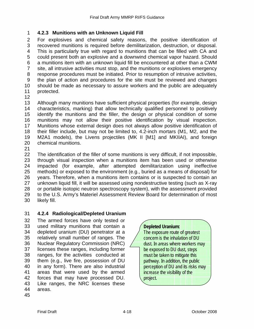
Final Draft Army MMRP RI/FS Guidance
Final Draft October 2008 4-18
4.2.3 Munitions with an Unknown Liquid Fill 1 For explosives and chemical safety reasons, the positive identification of 2 recovered munitions is required before demilitarization, destruction, or disposal. 3 This is particularly true with regard to munitions that can be filled with CA and 4 could present both an explosive and a downwind chemical vapor hazard. Should 5 a munitions item with an unknown liquid fill be encountered at other than a CWM 6 site, all intrusive activities must stop, and the munitions or explosives emergency 7 response procedures must be initiated. Prior to resumption of intrusive activities, 8 the plan of action and procedures for the site must be reviewed and changes 9 should be made as necessary to assure workers and the public are adequately 10 protected. 11 12 Although many munitions have sufficient physical properties (for example, design 13 characteristics, marking) that allow technically qualified personnel to positively 14 identify the munitions and the filler, the design or physical condition of some 15 munitions may not allow their positive identification by visual inspection. 16 Munitions whose external design does not always allow positive identification of 17 their filler include, but may not be limited to, 4.2-inch mortars (M1, M2, and the 18 M2A1 models), the Livens projectiles (MK II [M1] and MKIIAI), and foreign 19 chemical munitions. 20 21 The identification of the filler of some munitions is very difficult, if not impossible, 22 through visual inspection when a munitions item has been used or otherwise 23 impacted (for example, after attempted demilitarization using ineffective 24 methods) or exposed to the environment (e.g., buried as a means of disposal) for 25 years. Therefore, when a munitions item contains or is suspected to contain an 26 unknown liquid fill, it will be assessed using nondestructive testing (such as X-ray 27 or portable isotopic neutron spectroscopy system), with the assessment provided 28 to the U.S. Army’s Materiel Assessment Review Board for determination of most 29 likely fill. 30
4.2.4 Radiological/Depleted Uranium 31 The armed forces have only tested or 32 used military munitions that contain a 33 depleted uranium (DU) penetrator at a 34 relatively small number of ranges. The 35 Nuclear Regulatory Commission (NRC) 36 licenses these ranges, including former 37 ranges, for the activities conducted at 38 them (e.g., live fire, possession of DU 39 in any form). There are also industrial 40 areas that were used by the armed 41 forces that may have processed DU. 42 Like ranges, the NRC licenses these 43 areas. 44 45
Depleted Uranium: The exposure route of greatest concern is the inhalation of DU dust. In areas where workers may be exposed to DU dust, steps must be taken to mitigate this pathway. In addition, the public perception of DU and its risks may increase the visibility of the project.
Final Draft Army MMRP RI/FS Guidance
Final Draft October 2008 4-19
Recently, the Army became aware that, in the 1960s, several infantry units 1 assigned a nuclear mission using the Davy Crockett Nuclear Weapon System (a 2 recoilless rifle) used the M101 spotting round. The M101 was a 20-3 millimeter(mm) round that was approximately 7 inches long and contained about 4 6.7 ounces of DU. The DU in this round was used as ballast to allow the round to 5 mirror the trajectory of a training warhead that contained high explosives. This 6 round was used between 1962 and 1968. The Army currently is conducting 7 research, including on-site inspection, to determine the ranges on which the 8 M101 was used and to get these ranges appropriately licensed by the NRC. 9 10 DU has been used in military munitions in several ways: as a kinetic energy 11 penetrator to defeat armored targets, as ballast in the M101 spotting round, and 12 in minute quantities as a catalyst in epoxy. Epoxy that contains minute amounts 13 of DU is only used in the M86 Pursuit Deterrent Munitions and the Area Denial 14 Artillery Munitions. DU also has other military (e.g., protective armor for tanks) 15 and civilian applications. 16 17 DU, which is only weakly radioactive, is a heavy metal that is dense, strong, 18 hard. When used as a penetrator, DU becomes pyrophoric on impact with hard 19 targets (e.g., armored tanks). Unlike modern DU penetrators that can aerosolize 20 and ignite on impact with a hard target, the M101 was a low velocity round that 21 normally would break apart upon impact, depositing DU as relatively large 22 fragments on a range. 23 24 For munitions response, DU is addressed as an MC. DU is relatively harmless 25 unless ingested or absorbed into the bloodstream through open cuts. However, 26 DU dust may pose a potential inhalation hazard to response workers. The hazard 27 is related more to the toxicity of the dust than its radioactivity. DU that may be 28 found on ranges, including those at which the M101 spotting round was used, is: 29
• nonmagnetic, 30 • extremely heavy (about 50% more dense than lead), and 31 • jet-black lumps or bright yellow-green lumps or small particles. 32
33 In many cases, it may not be possible to identify areas containing DU with a 34 visual inspection. The radiation detection instruments used on site walks are 35 normally not sensitive enough to detect small deposits (quantities) of DU. 36 Therefore, information regarding the potential for DU generally comes from the 37 HRR or occasionally through the observation of the bright yellow oxide while on 38 site. Table 4-5 lists munitions that may contain DU. 39 40 41
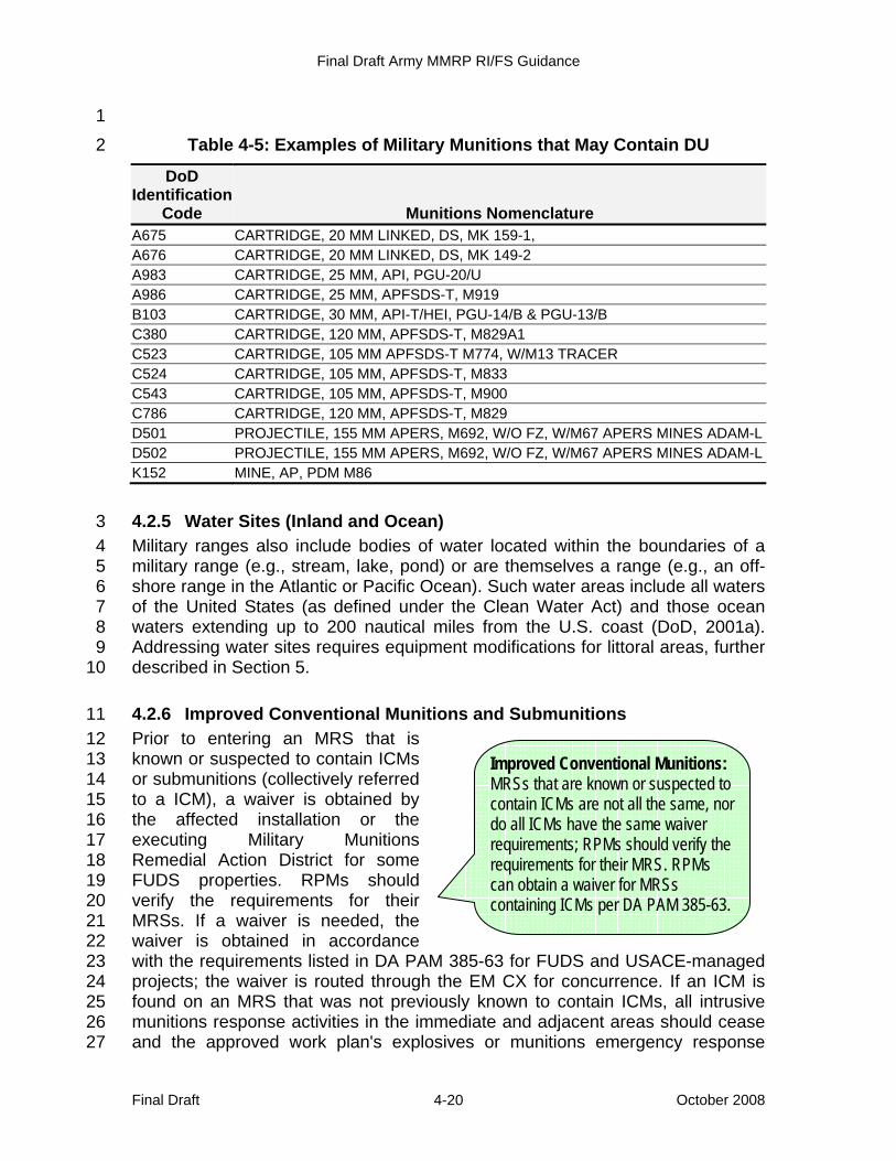
Final Draft Army MMRP RI/FS Guidance
Final Draft October 2008 4-20
1 Table 4-5: Examples of Military Munitions that May Contain DU 2
DoD Identification
Code Munitions Nomenclature A675 CARTRIDGE, 20 MM LINKED, DS, MK 159-1, A676 CARTRIDGE, 20 MM LINKED, DS, MK 149-2 A983 CARTRIDGE, 25 MM, API, PGU-20/U A986 CARTRIDGE, 25 MM, APFSDS-T, M919 B103 CARTRIDGE, 30 MM, API-T/HEI, PGU-14/B & PGU-13/B C380 CARTRIDGE, 120 MM, APFSDS-T, M829A1 C523 CARTRIDGE, 105 MM APFSDS-T M774, W/M13 TRACER C524 CARTRIDGE, 105 MM, APFSDS-T, M833 C543 CARTRIDGE, 105 MM, APFSDS-T, M900 C786 CARTRIDGE, 120 MM, APFSDS-T, M829 D501 PROJECTILE, 155 MM APERS, M692, W/O FZ, W/M67 APERS MINES ADAM-LD502 PROJECTILE, 155 MM APERS, M692, W/O FZ, W/M67 APERS MINES ADAM-LK152 MINE, AP, PDM M86
4.2.5 Water Sites (Inland and Ocean) 3 Military ranges also include bodies of water located within the boundaries of a 4 military range (e.g., stream, lake, pond) or are themselves a range (e.g., an off-5 shore range in the Atlantic or Pacific Ocean). Such water areas include all waters 6 of the United States (as defined under the Clean Water Act) and those ocean 7 waters extending up to 200 nautical miles from the U.S. coast (DoD, 2001a). 8 Addressing water sites requires equipment modifications for littoral areas, further 9 described in Section 5. 10
4.2.6 Improved Conventional Munitions and Submunitions 11 Prior to entering an MRS that is 12 known or suspected to contain ICMs 13 or submunitions (collectively referred 14 to a ICM), a waiver is obtained by 15 the affected installation or the 16 executing Military Munitions 17 Remedial Action District for some 18 FUDS properties. RPMs should 19 verify the requirements for their 20 MRSs. If a waiver is needed, the 21 waiver is obtained in accordance 22 with the requirements listed in DA PAM 385-63 for FUDS and USACE-managed 23 projects; the waiver is routed through the EM CX for concurrence. If an ICM is 24 found on an MRS that was not previously known to contain ICMs, all intrusive 25 munitions response activities in the immediate and adjacent areas should cease 26 and the approved work plan's explosives or munitions emergency response 27
Improved Conventional Munitions: MRSs that are known or suspected to contain ICMs are not all the same, nor do all ICMs have the same waiver requirements; RPMs should verify the requirements for their MRS. RPMs can obtain a waiver for MRSs containing ICMs per DA PAM 385-63.
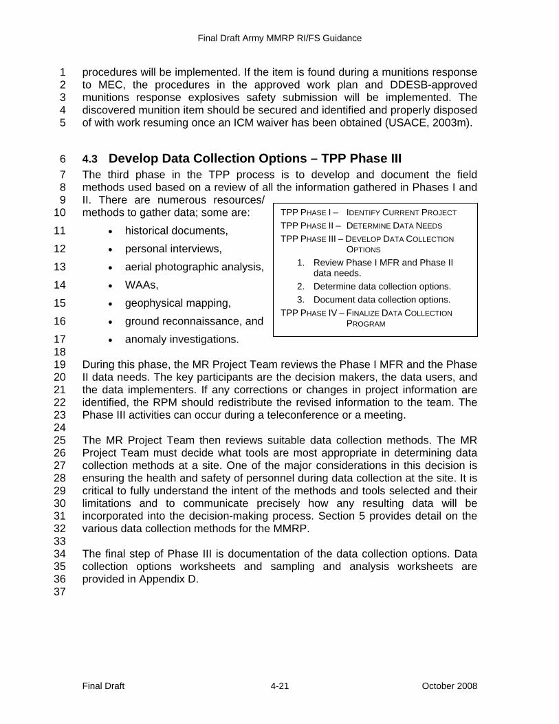
Final Draft Army MMRP RI/FS Guidance
Final Draft October 2008 4-21
procedures will be implemented. If the item is found during a munitions response 1 to MEC, the procedures in the approved work plan and DDESB-approved 2 munitions response explosives safety submission will be implemented. The 3 discovered munition item should be secured and identified and properly disposed 4 of with work resuming once an ICM waiver has been obtained (USACE, 2003m). 5
4.3 Develop Data Collection Options – TPP Phase III 6 The third phase in the TPP process is to develop and document the field 7 methods used based on a review of all the information gathered in Phases I and 8 II. There are numerous resources/ 9 methods to gather data; some are: 10
• historical documents, 11 • personal interviews, 12 • aerial photographic analysis, 13 • WAAs, 14 • geophysical mapping, 15 • ground reconnaissance, and 16 • anomaly investigations. 17
18 During this phase, the MR Project Team reviews the Phase I MFR and the Phase 19 II data needs. The key participants are the decision makers, the data users, and 20 the data implementers. If any corrections or changes in project information are 21 identified, the RPM should redistribute the revised information to the team. The 22 Phase III activities can occur during a teleconference or a meeting. 23 24 The MR Project Team then reviews suitable data collection methods. The MR 25 Project Team must decide what tools are most appropriate in determining data 26 collection methods at a site. One of the major considerations in this decision is 27 ensuring the health and safety of personnel during data collection at the site. It is 28 critical to fully understand the intent of the methods and tools selected and their 29 limitations and to communicate precisely how any resulting data will be 30 incorporated into the decision-making process. Section 5 provides detail on the 31 various data collection methods for the MMRP. 32 33 The final step of Phase III is documentation of the data collection options. Data 34 collection options worksheets and sampling and analysis worksheets are 35 provided in Appendix D. 36 37
TPP PHASE I – IDENTIFY CURRENT PROJECT TPP PHASE II – DETERMINE DATA NEEDS TPP PHASE III – DEVELOP DATA COLLECTION
OPTIONS 1. Review Phase I MFR and Phase II
data needs. 2. Determine data collection options. 3. Document data collection options.
TPP PHASE IV – FINALIZE DATA COLLECTION PROGRAM
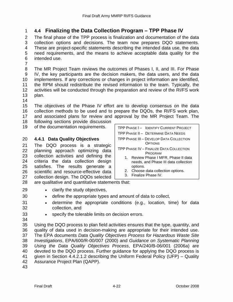
Final Draft Army MMRP RI/FS Guidance
Final Draft October 2008 4-22
4.4 Finalizing the Data Collection Program – TPP Phase IV 1 The final phase of the TPP process is finalization and documentation of the data 2 collection options and decisions. The team now prepares DQO statements. 3 These are project-specific statements describing the intended data use, the data 4 need requirements, and the means to achieve acceptable data quality for the 5 intended use. 6 7 The MR Project Team reviews the outcomes of Phases I, II, and III. For Phase 8 IV, the key participants are the decision makers, the data users, and the data 9 implementers. If any corrections or changes in project information are identified, 10 the RPM should redistribute the revised information to the team. Typically, the 11 activities will be conducted through the preparation and review of the RI/FS work 12 plan. 13 14 The objectives of the Phase IV effort are to develop consensus on the data 15 collection methods to be used and to prepare the DQOs, the RI/FS work plan, 16 and associated plans for review and approval by the MR Project Team. The 17 following sections provide discussion 18 of the documentation requirements. 19
4.4.1 Data Quality Objectives 20 The DQO process is a strategic 21 planning approach optimizing data 22 collection activities and defining the 23 criteria the data collection design 24 satisfies. The results generate a 25 scientific and resource-effective data 26 collection design. The DQOs selected 27 are qualitative and quantitative statements that: 28
• clarify the study objectives, 29 • define the appropriate types and amount of data to collect, 30 • determine the appropriate conditions (e.g., location, time) for data 31
collection, and 32 • specify the tolerable limits on decision errors. 33
34 Using the DQO process to plan field activities ensures that the type, quantity, and 35 quality of data used in decision-making are appropriate for their intended use. 36 The EPA documents Data Quality Objectives Process for Hazardous Waste Site 37 Investigations, EPA/600/R-00/007 (2000) and Guidance on Systematic Planning 38 Using the Data Quality Objectives Process, EPA/240/B-06/001 (2006a) are 39 devoted to the DQO process. Further guidance for applying the DQO process is 40 given in Section 4.4.2.1.2 describing the Uniform Federal Policy (UFP) – Quality 41 Assurance Project Plan (QAPP). 42 43
TPP PHASE I – IDENTIFY CURRENT PROJECT TPP PHASE II – DETERMINE DATA NEEDS TPP PHASE III – DEVELOP DATA COLLECTION
OPTIONS TPP PHASE IV – FINALIZE DATA COLLECTION
PROGRAM 1. Review Phase I MFR, Phase II data
needs, and Phase III data collection options.
2. Choose data collection options. 3. Finalize Phase IV.
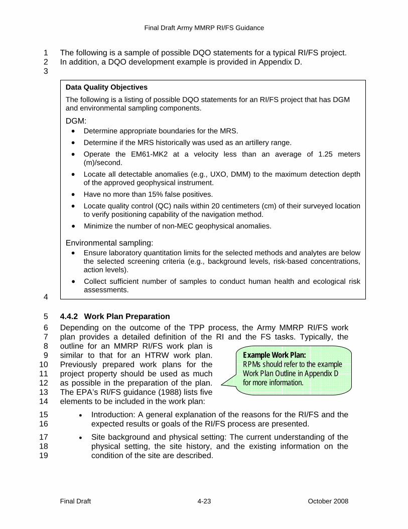
Final Draft Army MMRP RI/FS Guidance
Final Draft October 2008 4-23
The following is a sample of possible DQO statements for a typical RI/FS project. 1 In addition, a DQO development example is provided in Appendix D. 2 3
4
4.4.2 Work Plan Preparation 5 Depending on the outcome of the TPP process, the Army MMRP RI/FS work 6 plan provides a detailed definition of the RI and the FS tasks. Typically, the 7 outline for an MMRP RI/FS work plan is 8 similar to that for an HTRW work plan. 9 Previously prepared work plans for the 10 project property should be used as much 11 as possible in the preparation of the plan. 12 The EPA’s RI/FS guidance (1988) lists five 13 elements to be included in the work plan: 14
• Introduction: A general explanation of the reasons for the RI/FS and the 15 expected results or goals of the RI/FS process are presented. 16
• Site background and physical setting: The current understanding of the 17 physical setting, the site history, and the existing information on the 18 condition of the site are described. 19
Data Quality Objectives The following is a listing of possible DQO statements for an RI/FS project that has DGM and environmental sampling components.
DGM: • Determine appropriate boundaries for the MRS. • Determine if the MRS historically was used as an artillery range. • Operate the EM61-MK2 at a velocity less than an average of 1.25 meters
(m)/second. • Locate all detectable anomalies (e.g., UXO, DMM) to the maximum detection depth
of the approved geophysical instrument. • Have no more than 15% false positives. • Locate quality control (QC) nails within 20 centimeters (cm) of their surveyed location
to verify positioning capability of the navigation method. • Minimize the number of non-MEC geophysical anomalies.
Environmental sampling: • Ensure laboratory quantitation limits for the selected methods and analytes are below
the selected screening criteria (e.g., background levels, risk-based concentrations, action levels).
• Collect sufficient number of samples to conduct human health and ecological risk assessments.
Example Work Plan: RPMs should refer to the example Work Plan Outline in Appendix D for more information.
Final Draft Army MMRP RI/FS Guidance
Final Draft October 2008 4-24
• Initial evaluation: The CSM developed during scoping is presented, 1 describing the potential migration and exposure pathways and the 2 preliminary assessment of human health and environmental impacts. 3 Outcome of the TPP process is presented. 4
• Work plan rationale: Data requirements for both the risk assessment 5 and the alternatives evaluation identified during the formulation of the 6 DQOs are documented, and the work plan approach is presented to 7 illustrate how the data collection options will satisfy data needs. 8
• RI/FS tasks: The tasks to be performed during the RI/FS are presented. 9 This description incorporates RI site characterization tasks identified in 10 the QAPP and the field sampling plan (FSP), the data evaluation 11 methods identified during scoping, and the preliminary determination of 12 tasks to be conducted after site characterization. 13
14 The Phase I MFR, Phase II data needs analysis, and Phase III data collection 15 options worksheets are attached to the work plan. Additional standard 16 attachments to the project work plan, described below, provide details of the 17 specific data collection activities designed to support the objectives of the project, 18 as set forth in the work plan. Information in the project work plan and the 19 attachments should not be redundant (USACE, 2004c). 20
4.4.2.1 Sampling and Analysis Plan 21 When sampling and analysis are required, Sampling and Analysis Plans (SAPs) 22 are prepared, ensuring the data obtained are of the quantity and quality 23 necessary to support the decisions to be made (EPA, 1988). The SAP for RI/FS 24 activities must be reviewed and approved by the EPA in accordance with NCP 25 Section 300.430(b)(8) for all NPL sites in the Army inventory. The SAP consists 26 of two parts: an FSP and a QAPP. The FSP provides guidance for all fieldwork 27 by defining in detail the sampling and field data-gathering methods to be used on 28 the project. The QAPP details the necessary quality assurance (QA), QC, and 29 other technical activities implemented to ensure the results of the work performed 30 satisfy the stated performance criteria. The FSP and QAPP are submitted as a 31 single document (although they may be bound separately to facilitate the use of 32 the FSP in the field) (USACE, 2004c). 33
4.4.2.1.1 Field Sampling Plan 34 The FSP shall contain necessary technical detail and direction for the field 35 personnel to understand sampling and field measurement requirements. The 36 FSP shall provide a comprehensive description and full detail for personnel to 37 perform all on-site activities required to attain project DQOs. The outputs of the 38 TPP process, including the DQOs, are used to develop the sampling design for 39 the FSP and to prepare the QAPP. 40 41 For MEC investigation, the FSP should contain specific procedures for the 42 proposed geophysical and any intrusive investigations to be performed. The FSP 43

Final Draft Army MMRP RI/FS Guidance
Final Draft October 2008 4-25
should specifically address the protective measures that will be taken to ensure 1 explosives safety during intrusive investigation of anomalies and removal actions 2 that involve MEC. The following munitions response elements are required: 3
• GPO Plan: The GPO Plan is used to provide details of the approach, 4 methods, and operational procedures to be (1) employed to perform 5 GPOs for munitions response or other munitions responses and (2) 6 documented as part of the Geophysical Investigation Plan. 7
• Geophysical Investigation Plan: The Geophysical Investigation Plan is 8 used to provide details of the approach, methods, and operational 9 procedures employed in performing geophysical investigations. 10
• Geospatial Information and Electronic Submittals Plan: The Geospatial 11 Information and Electronic Submittals are used to describe methods, 12 equipment, and accuracy for conducting location surveys and mapping 13 of munitions response or other munitions-related projects and the 14 subsequent development of geographic information system databases 15 to support the mapping and document (paper and electronic) production 16 process. 17
• Intrusive Investigation Plan: The Intrusive Investigation Plan documents: 18 ° locations for investigating anomalies or sampling for MC; 19 ° procedures for sampling and investigating anomalies; 20 ° personnel qualifications; 21 ° procedures for MEC accountability and records management; 22 ° the munition with the greatest fragmentation distance (MGFD) for 23
each MRS; 24 ° minimum safety distance based on the MGFD; 25 ° identification; 26 ° procedures for MEC removal, storage and disposal; and 27 ° procedures for processing Material Potentially Presenting an 28
Explosive Hazard (MPPEH) and material documented as either 29 safe or hazardous. 30
• Investigation-Derived Waste Plan: The Investigative-Derived Waste Plan 31 is used to detail requirements for handling and disposing of 32 investigation-derived waste. 33
34 For MC sampling, the FSP should consist of the following six elements: 35
• Site background 36 • Sampling objectives 37 • Sampling location and frequency 38 • Sample designation 39
Final Draft Army MMRP RI/FS Guidance
Final Draft October 2008 4-26
• Sampling equipment and procedures 1 • Sample handling and analysis (USAEC, 1998) 2
Additional guidance for preparing the FSP for MC can be found in EM 200-1-3 3 (USACE, 2001a) and EM 1110-1-4009 (USACE, 2007). Chemistry requirements 4 for CWM projects shall be according to Engineer Pamphlet (EP) 75-1-3 (USACE, 5 2004). 6
4.4.2.1.2 Quality Assurance Project Plan 7 The QAPP focuses primarily on the analytical methods and QA/QC procedures 8 used to analyze the samples and manage data. The DoD is voluntarily adopting 9 the requirements of the UFP-QAPP Manual. Use of the UFP-QAPP Manual will 10 be phased in over time as new and substantially revised QAPPs are developed. 11 On 7 June 2005, the EPA issued OSWER Directive 9272.0-17 Implementation of 12 the Uniform Federal Policy for Quality Assurance Project Plans (UFP-QAPP) at 13 Federal Facility Hazardous Waste Sites. This has been implemented by DoD 14 Instruction 4715.5 Environmental Quality Systems (DoD, 2006). This directive 15 requests EPA Regions to immediately begin implementation (as appropriate) of 16 the UFP-QAPP and its associated documents. The UFP-QAPP is designated for 17 use in federal facility projects where environmental data are collected. Designed 18 to be applicable for all environmental data collection related to hazardous waste 19 investigations (e.g., cleanup under CERCLA, RCRA, BRAC), compliance with the 20 UFP-QAPP (form, content, and minimum QA/QC specifications) is considered 21 adequate conformance with the EPA QA/G-5 Guidance (2002) and any regional 22 guidance on the preparation of QAPPs. The UFP-QAPP manual, templates, and 23 examples are available at http://www.epa.gov/fedfac/documents/ 24 qualityassurance.htm. The UFP-QAPP supersedes existing region-specific 25 QAPP guidance for federal facility hazardous waste activities (EPA, 2005b). 26
4.4.2.2 Accident Prevention Plan / Site Safety and Health Plan 27 An approved Accident Prevention Plan (APP) and Site Safety and Health Plan 28 (SSHP), an appendix to the APP, with an Activities Hazard Analysis is required 29 when conducting on-site munitions response activities (e.g., soil sampling, 30 construction of a geophysical test plot, geophysical mapping, anomaly 31 investigation). The APP/SSHP shall address all occupational safety and health 32 hazards associated with site investigation, as required by the Occupational 33 Safety and Health Administration. The USACE has multiple guidance documents 34 on preparing APP/SSHPs, including ER 385-1-92, ER 385-1-95, EP 75-1-2, EP 35 75-1-3, ER 385-1-95a, and EM 385-1-1 (USACE, 2000c, 2006b, 2000a, 2004a, 36 2003l, and 2003j). For FUDS and USACE-managed projects, the APP/SSHP 37 must be coordinated with the EM CX before on-site work begins (USACE, 38 2000a). 39
Final Draft Army MMRP RI/FS Guidance
Final Draft October 2008 4-27
4.4.2.3 Department of Defense Explosives Safety Board Required Safety 1 Submissions and Site Plans 2
An explosives or, when appropriate, a CWM site plan (ESP or CSP) is required 3 for MRS investigations or characterizations that involve the intentional physical 4 contact with MEC or CA, regardless of configuration. Such site plans will 5 address areas (e.g., magazines) used for the storage of commercial or military 6 demolition explosives, MEC or CA, regardless of configuration; planned or 7 established demolition or disposal areas; and the MRA, MRS, or response area 8 boundaries. MRS investigation and characterization are used to collect the 9 information needed to design the required munitions response and to prepare, as 10 appropriate, an explosives safety submission (ESS) or chemical safety 11 submission (CSS) for the selected response (DoD, 2005a). See DOD 6055.09-12 STD, Chapter 12 for complete details concerning ESP/CSP and ESS/CSS 13 requirements. 14 15 The GC, or designated authority, is responsible for execution of the installation’s 16 Army DERP and approval of the DDESB-required s site plan submitted through 17 the DRU and USATCES to the DDESB for approval with DoD Ammunition and 18 Explosives Safety Standards (DoDD 6055.9-STD; DDESB, 2008) and with DoD 19 and Army explosives safety policies. The RPM should start the submittal review 20 process as early in the investigative phase as possible due to the length of time 21 required to obtain DDESB approval for the required submittal (i.e., 4 to 6 22 months). For FUDS, the EM CX will provide the mandatory DRU approval 23 memorandum for HQUSACE per EP 385-1-95 (USACE, 2006b). The DRU may 24 request an interim Army approval from USATCES if the situation or schedule 25 warrants such a request. 26
4.4.2.4 Additional Planning Documents 27 Based on the characteristics of the MRS, additional planning documents may be 28 required. The following sections summarize the various planning documents that 29 may apply to the RI/FS at an MRS. 30
4.4.2.4.1 Environmental Protection Plan 31 The Environmental Protection Plan (EPP) is used to describe the approach, 32 methods, and operational procedures employed to protect the natural 33 environment during performance of all tasks. The EPP is coordinated with the 34 installation for all active installations. Example components of an EPP can be 35 found in Data Item Description (DID) MR-005-12 (USACE, 2003f). 36
4.4.2.4.2 Institutional Analysis Plan 37 An Institutional Analysis identifies and analyzes the institutional framework 38 necessary to support the development of institutional controls (ICs), if any, 39 required to help ensure the remedy is protective. The purpose of this analysis is 40 to gather background information and document which stakeholders have 41 jurisdiction over the MRS in question and to assess the capability and willingness 42 of these entities to assert ICs that would protect the public from any hazards 43
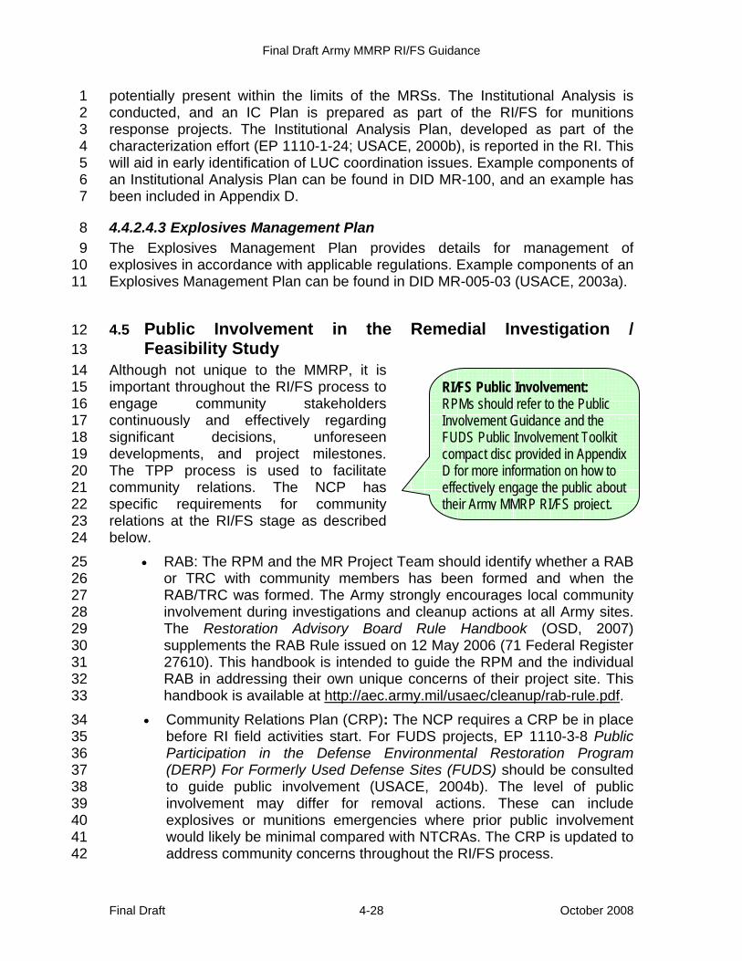
Final Draft Army MMRP RI/FS Guidance
Final Draft October 2008 4-28
potentially present within the limits of the MRSs. The Institutional Analysis is 1 conducted, and an IC Plan is prepared as part of the RI/FS for munitions 2 response projects. The Institutional Analysis Plan, developed as part of the 3 characterization effort (EP 1110-1-24; USACE, 2000b), is reported in the RI. This 4 will aid in early identification of LUC coordination issues. Example components of 5 an Institutional Analysis Plan can be found in DID MR-100, and an example has 6 been included in Appendix D. 7
4.4.2.4.3 Explosives Management Plan 8 The Explosives Management Plan provides details for management of 9 explosives in accordance with applicable regulations. Example components of an 10 Explosives Management Plan can be found in DID MR-005-03 (USACE, 2003a). 11
4.5 Public Involvement in the Remedial Investigation / 12 Feasibility Study 13
Although not unique to the MMRP, it is 14 important throughout the RI/FS process to 15 engage community stakeholders 16 continuously and effectively regarding 17 significant decisions, unforeseen 18 developments, and project milestones. 19 The TPP process is used to facilitate 20 community relations. The NCP has 21 specific requirements for community 22 relations at the RI/FS stage as described 23 below. 24
• RAB: The RPM and the MR Project Team should identify whether a RAB 25 or TRC with community members has been formed and when the 26 RAB/TRC was formed. The Army strongly encourages local community 27 involvement during investigations and cleanup actions at all Army sites. 28 The Restoration Advisory Board Rule Handbook (OSD, 2007) 29 supplements the RAB Rule issued on 12 May 2006 (71 Federal Register 30 27610). This handbook is intended to guide the RPM and the individual 31 RAB in addressing their own unique concerns of their project site. This 32 handbook is available at http://aec.army.mil/usaec/cleanup/rab-rule.pdf. 33
• Community Relations Plan (CRP): The NCP requires a CRP be in place 34 before RI field activities start. For FUDS projects, EP 1110-3-8 Public 35 Participation in the Defense Environmental Restoration Program 36 (DERP) For Formerly Used Defense Sites (FUDS) should be consulted 37 to guide public involvement (USACE, 2004b). The level of public 38 involvement may differ for removal actions. These can include 39 explosives or munitions emergencies where prior public involvement 40 would likely be minimal compared with NTCRAs. The CRP is updated to 41 address community concerns throughout the RI/FS process. 42
RI/FS Public Involvement: RPMs should refer to the Public Involvement Guidance and the FUDS Public Involvement Toolkit compact disc provided in Appendix D for more information on how to effectively engage the public about their Army MMRP RI/FS project.
Final Draft Army MMRP RI/FS Guidance
Final Draft October 2008 4-29
• Administrative Record: The NCP 40 CFR 300.805(a) requires the 1 Administrative Record file be initiated at the start of the RI phase for a 2 remedial action, upon signature of the EE/CA Approval Memorandum 3 for an NTCRA or within 60 days of beginning on-site activities for a 4 TCRA. Notification of the availability of the Administrative Record file 5 shall be made, at a minimum, in a major local newspaper of general 6 circulation (USACE, 2004c). 7 For munitions responses under the MMRP, installations shall have a 8 permanent record of the data gathered to characterize a site and a clear 9 audit trail of pertinent data analysis and resulting decisions and actions. 10 To the maximum extent practicable, the permanent record shall include 11 geophysical sensor data that are digitally recorded and georeferenced. 12 When digitally recording and georeferencing the geophysical sensor 13 data is impractical, ACSIM approval will be required. These data shall 14 be included in the Administrative Record (U.S. Army, 2004a). 15
4.5.1 Rights of Entry 16 To fulfill its CERCLA responsibilities per EO 12580, the Army has the authority to 17 conduct remedial actions outside of the installation boundaries, where the 18 installation is reasonably considered to be the sole or the major source of the 19 CERCLA release. Off-site actions can be complex and often require a right of 20 entry (ROE) from the property owner and extensive coordination with the 21 property owner and community because of the lack of Army control over the 22 property. By DoD policy, only EOD units may respond to a request for support of 23 an explosives or munitions emergency (US Army, 2004a). 24 25 The USACE District Chief of Real Estate must obtain all ROEs, regardless of 26 their purpose. There are no cases where installations can obtain ROEs without 27 USACE participation. The RPM is responsible for obtaining access agreements 28 to limit government and contractor liabilities. The USACE District Chief of Real 29 Estate and/or the HQUSACE Deputy Chief of Staff for Real Estate shall be 30 consulted for additional information and project-specific issues. 31 32 The initial step in obtaining property access is the preparation of the landowner 33 notification letter. The project manager should coordinate preparation of the 34 Landowner Notification Letter with their Public Affairs Office. It is necessary to 35 recognize the potential effects of entry, including traverse of other properties, 36 upon a parcel of land. Routes should be selected to avoid or minimize such 37 disturbances. 38 39 In some cases, property owners may not allow the Army access to their 40 properties. For projects or properties where MEC are reasonably believed to be 41 present and access is denied, the Army will notify the Office of the DUSD(I&E) of 42 the circumstances surrounding the denial of ROE. The Army shall make 43 appropriate referral to the Attorney General of the United States per CERCLA 44 §104(e)(5)(B) (DoD, 2001a). 45
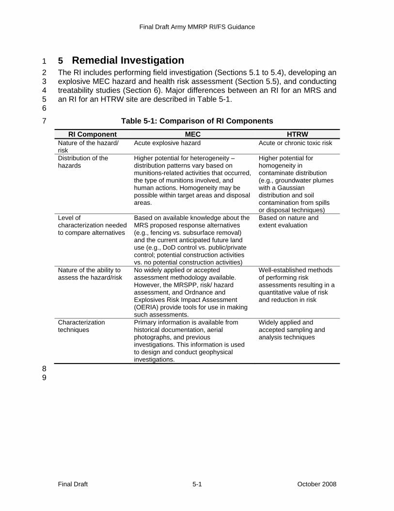
Final Draft Army MMRP RI/FS Guidance
Final Draft October 2008 5-1
5 Remedial Investigation 1 The RI includes performing field investigation (Sections 5.1 to 5.4), developing an 2 explosive MEC hazard and health risk assessment (Section 5.5), and conducting 3 treatability studies (Section 6). Major differences between an RI for an MRS and 4 an RI for an HTRW site are described in Table 5-1. 5 6
Table 5-1: Comparison of RI Components 7
RI Component MEC HTRW Nature of the hazard/ risk
Acute explosive hazard Acute or chronic toxic risk
Distribution of the hazards
Higher potential for heterogeneity – distribution patterns vary based on munitions-related activities that occurred, the type of munitions involved, and human actions. Homogeneity may be possible within target areas and disposal areas.
Higher potential for homogeneity in contaminate distribution (e.g., groundwater plumes with a Gaussian distribution and soil contamination from spills or disposal techniques)
Level of characterization needed to compare alternatives
Based on available knowledge about the MRS proposed response alternatives (e.g., fencing vs. subsurface removal) and the current anticipated future land use (e.g., DoD control vs. public/private control; potential construction activities vs. no potential construction activities)
Based on nature and extent evaluation
Nature of the ability to assess the hazard/risk
No widely applied or accepted assessment methodology available. However, the MRSPP, risk/ hazard assessment, and Ordnance and Explosives Risk Impact Assessment (OERIA) provide tools for use in making such assessments.
Well-established methods of performing risk assessments resulting in a quantitative value of risk and reduction in risk
Characterization techniques
Primary information is available from historical documentation, aerial photographs, and previous investigations. This information is used to design and conduct geophysical investigations.
Widely applied and accepted sampling and analysis techniques
8 9

Final Draft Army MMRP RI/FS Guidance
Final Draft October 2008 5-2
Figure 5-1 details the process flow diagram involved in an MMRP RI. 1
2 Figure 5-1: Flow diagram for the RI 3
Reevaluate data
needs?
MEC investigations MC investigations
Sample analysis (field and laboratory)
Data evaluation -site characterization
Geophysical survey
Geophysical dataanalysis (dig list)
Reacquisition of anomalies
Intrusive investigation of
selected anomalies
MEC?MPPEHevaluation
MEC disposal- -
Anomalies surveyed,mapped, and documented
on dig sheets
RI/FS scoping
Data evaluation -hazard / riskassessment
Datasufficient to
develop alternatives?
Can NFA be
obtained?
Draft RI report
Re-investigation(Section 4)
Data management•Field procedures•Field measurements
Data management•Laboratory•Field measurements
Data management•Analytical data•Geophysical data•Intrusive data
NFA decisiondocuments
FS
Note : The need for interim measures (TCRA, NTCRA, or interim remedial action) is assessed throughout the process.See Section 5.7.
BIP = blow in place
No
Yes
Yes
No
No
Yes
Yes No
GPO
Sufficient data toconduct hazard / risk assessment?
Not for MEC Not for MC
Yes
Reevaluate data
needs?
MEC investigations MC investigations
Sample analysis (field and laboratory)
Data evaluation -site characterization
Geophysical survey
Geophysical dataanalysis (dig list)
Reacquisition of anomalies
Intrusive investigation of
selected anomalies
MPPEH evaluation
Poses explosivehazard?
Release forrecycling
Destroy by approved means per MRESS
(BIP, disposal on site and/or off site)
Transfer to qualified
receiver
Anomalies surveyed,mapped, and documented
on dig sheets
RI/FS scoping
Data evaluation -hazard / riskassessment
Datasufficient to
develop alternatives?
Can NFA be
obtained?
Draft RI report
Re-scopeinvestigation(Section 4)
Data management•Field procedures•Field measurements
Data management•Laboratory•Field measurements
Data management•Analytical data•Geophysical data•Intrusive data
NFA decisiondocuments
FS
Note
BIP = blow in place
No
Yes
Yes
No
No
Yes
Yes No
GPO
Sufficient data toconduct hazard / risk assessment?
Not for MEC Not for MC
Yes
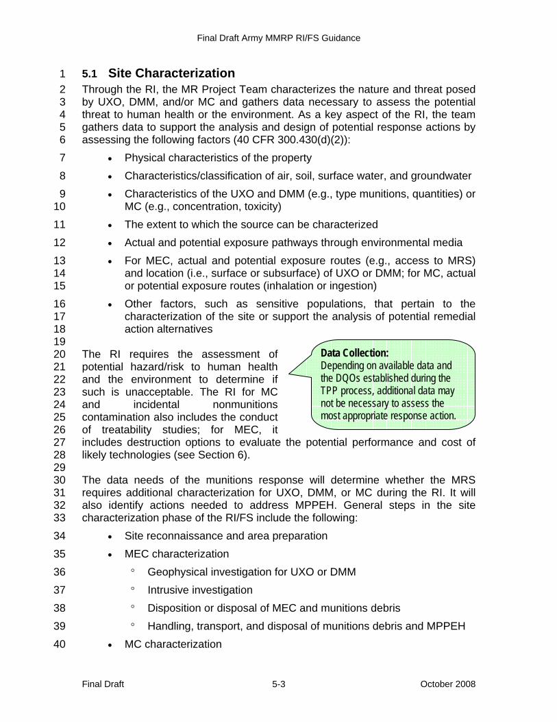
Final Draft Army MMRP RI/FS Guidance
Final Draft October 2008 5-3
5.1 Site Characterization 1 Through the RI, the MR Project Team characterizes the nature and threat posed 2 by UXO, DMM, and/or MC and gathers data necessary to assess the potential 3 threat to human health or the environment. As a key aspect of the RI, the team 4 gathers data to support the analysis and design of potential response actions by 5 assessing the following factors (40 CFR 300.430(d)(2)): 6
• Physical characteristics of the property 7 • Characteristics/classification of air, soil, surface water, and groundwater 8 • Characteristics of the UXO and DMM (e.g., type munitions, quantities) or 9
MC (e.g., concentration, toxicity) 10 • The extent to which the source can be characterized 11 • Actual and potential exposure pathways through environmental media 12 • For MEC, actual and potential exposure routes (e.g., access to MRS) 13
and location (i.e., surface or subsurface) of UXO or DMM; for MC, actual 14 or potential exposure routes (inhalation or ingestion) 15
• Other factors, such as sensitive populations, that pertain to the 16 characterization of the site or support the analysis of potential remedial 17 action alternatives 18
19 The RI requires the assessment of 20 potential hazard/risk to human health 21 and the environment to determine if 22 such is unacceptable. The RI for MC 23 and incidental nonmunitions 24 contamination also includes the conduct 25 of treatability studies; for MEC, it 26 includes destruction options to evaluate the potential performance and cost of 27 likely technologies (see Section 6). 28 29 The data needs of the munitions response will determine whether the MRS 30 requires additional characterization for UXO, DMM, or MC during the RI. It will 31 also identify actions needed to address MPPEH. General steps in the site 32 characterization phase of the RI/FS include the following: 33
• Site reconnaissance and area preparation 34 • MEC characterization 35
° Geophysical investigation for UXO or DMM 36 ° Intrusive investigation 37 ° Disposition or disposal of MEC and munitions debris 38 ° Handling, transport, and disposal of munitions debris and MPPEH 39
• MC characterization 40
Data Collection: Depending on available data and the DQOs established during the TPP process, additional data may not be necessary to assess the most appropriate response action.
Final Draft Army MMRP RI/FS Guidance
Final Draft October 2008 5-4
° Sampling 1 ° Analysis 2
• Data collection and recording 3 • Baseline explosive hazard and health risk assessments 4
5.2 Munitions Response Site Characterization for Certain 5 Categories of Munitions and Explosives of Concern 6 (Unexploded Ordnance and Discarded Military Munitions) 7
The data needs for an MRS are determined during the scoping phase of RI/FS 8 through the TPP process as described in Section 4. Data needs are directly 9 linked to the decisions to be made at the MRS. Therefore, the level of 10 characterization for each MRS may vary from no additional investigation for two 11 common categories of MEC (i.e., UXO and DMM) to extensive geophysical 12 investigation. Again, the purpose of the RI is not to eliminate all uncertainty, but 13 to sufficiently characterize the MRS for response alternative selection. 14 15 As discussed previously, the main variation in an MRS RI/FS is the potential 16 need to use geophysical technology to characterize the site. However, on a case-17 by-case basis, the MR Project Team must evaluate whether conducting a 18 geophysical investigation is the best way to fill the data needs for an MRS (see 19 Case Study). Although geophysical data provide a great deal of information 20 about a site, they are not required for all response alternatives (i.e., NFA, LUCs, 21 and surface removal). The applicability of geophysical investigations depends on 22 the information known about the site (e.g., presence of MEC, historical use), 23 property ownership (e.g., DoD, federal, state), current, determined, or reasonably 24 anticipated future land use, the likely response alternative, and MR Project Team 25 criteria. 26 27 Geophysical investigations provide data about the potential for MEC, specifically 28 UXO and DMM, to be present in the subsurface. Geophysical investigations 29 typically involve three phases. The first phase is the GPO, allowing for the 30 selection of the most appropriate technology based on the site conditions and 31 anticipated MEC targets. The second phase is the geophysical survey; 32 geophysical instrumentation is used to survey the area. Geophysical data are 33 analyzed and interpreted to identify anomalies for intrusive investigation. The 34 third phase is the reacquiring of target anomalies for intrusive investigation. 35 During this third phase, all anomalies selected for excavation are physically 36 reestablished by precise survey methods, mapped, documented on dig sheets, 37 and intrusively investigated. The exception to this is when the selected data 38 collection approach consists of using a magnetometer and digging the anomalies 39 (“mag-and-dig”) or using a magnetometer and flagging the anomalies for later 40 excavation (“mag-and-flag”) (USACE, 2002). 41 42
Final Draft Army MMRP RI/FS Guidance
Final Draft October 2008 5-5
Prior to a geophysical survey, the site will need to be prepared for the use of 1 geophysical instruments. Site preparation activities typically consist of evaluating 2 safety hazards, clearing at least some vegetation, and removing surface 3 munitions and surface metallic clutter. Vegetation removal and removal 4 clearance help to ensure that a munitions response can be safely and effectively 5 conducted. Performing a surface clearance removal and clearing the MRS of as 6 much vegetation and surface debris as possible helps ensure the safety of 7 munitions response personnel, allows a better view of the area being worked, 8 improves access, and reduces any metallic clutter present to optimize the 9 performance of geophysical instruments in a given environment. 10 11 When geophysically surveying a site, there are two choices: either survey the 12 entire site or survey a representative portion of the site and infer the results 13 across the whole. On relatively small sites, it can be efficient in terms of cost, 14 schedule, and environmental impact to map the entire area. However, large sites 15 can present significant cost, schedule, access, and environmental impact 16 challenges that preclude geophysically mapping large areas as a method of site 17 characterization. Various site sampling methodologies are discussed in Section 18 5.3.2. 19 20 After a site has been geophysically mapped, multiple anomalies are likely to have 21 been located. Figure 5-2 shows the results of geophysical mapping. When using 22 mag-and-flag, anomalies are marked as flags at the location of each subsurface 23 anomaly. For munitions responses where digital geophysical methods are used, 24 the geophysicist evaluates and selects anomalies to be investigated, or dug, with 25 the help of analytical software. In either case, a portion of the anomalies must be 26 excavated by qualified UXO personnel to determine if an anomaly is MEC (UXO 27 or DMM) or some other feature. However, depending on historical munitions-28 related uses (e.g., impact area, OD site) or the current uses (e.g., developed 29 areas), the number of anomalies detected on some MRSs may range from 30 several dozen to several thousand per acre, most of which may be small metallic 31 fragments. When this occurs, a clear understanding of the geological background 32 and consideration of use of statistical investigation methods at the MRS may be 33 necessary. Section 5.3.3 discusses available statistical sampling techniques. 34 35 Computer-based evaluation is an important tool for interpreting geophysical data. 36 The MR Project Team must consider which geophysical tool (digital vs. analog, 37 see Section 5.2.1) to use during the discrimination and anomaly selection 38 process. The MR Project Team must ensure that it develops a transparent and 39 inclusive process of analyzing the geophysical data and provides hard copy of 40 the data and the list of anomalies selected for investigation (i.e., digital dig 41 sheets) to stakeholders. The process, assumptions, and procedures for 42 interpreting geophysical data should be clearly outlined in the work plan, and any 43 deviations should be discussed with the MR Project Team prior to finalizing the 44 “dig list.” 45
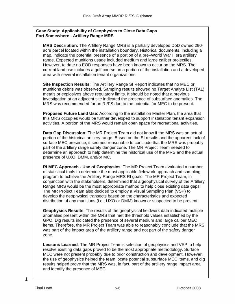
Final Draft Army MMRP RI/FS Guidance
Final Draft October 2008 5-6
1
Case Study: Applicability of Geophysics to Close Data Gaps Fort Somewhere - Artillery Range MRS
MRS Description: The Artillery Range MRS is a partially developed DoD owned 290-acre parcel located within the installation boundary. Historical documents, including a map, indicate the potential presence of a portion of a pre–World War II era artillery range. Expected munitions usage included medium and large caliber projectiles. However, to date no EOD responses have been known to occur on the MRS. The current land use includes a golf course on a portion of the installation and a developed area with several installation tenant organizations. Site Inspection Results: The Artillery Range SI Report indicates that no MEC or munitions debris was observed. Sampling results showed no Target Analyte List (TAL) metals or explosives above regulatory limits. It should be noted that a previous investigation at an adjacent site indicated the presence of subsurface anomalies. The MRS was recommended for an RI/FS due to the potential for MEC to be present. Proposed Future Land Use: According to the installation Master Plan, the area that this MRS occupies would be further developed to support installation tenant expansion activities. A portion of the MRS would remain open space for recreational activities. Data Gap Discussion: The MR Project Team did not know if the MRS was an actual portion of the historical artillery range. Based on the SI results and the apparent lack of surface MEC presence, it seemed reasonable to conclude that the MRS was probably part of the artillery range safety danger zone. The MR Project Team needed to determine an approach to help determine the historical use of the MRS and the actual presence of UXO, DMM, and/or MC. RI MEC Approach - Use of Geophysics: The MR Project Team evaluated a number of statistical tools to determine the most applicable fieldwork approach and sampling program to achieve the Artillery Range MRS RI goals. The MR Project Team, in conjunction with the stakeholders, determined that a geophysical survey of the Artillery Range MRS would be the most appropriate method to help close existing data gaps. The MR Project Team also decided to employ a Visual Sampling Plan (VSP) to develop the geophysical transects based on the characteristics and expected distribution of any munitions (i.e., UXO or DMM) known or suspected to be present. Geophysics Results: The results of the geophysical fieldwork data indicated multiple anomalies present within the MRS that met the threshold values established by the GPO. Dig results indicated the presence of several medium and large caliber MEC items. Therefore, the MR Project Team was able to reasonably conclude that the MRS was part of the impact area of the artillery range and not part of the safety danger zone. Lessons Learned: The MR Project Team’s selection of geophysics and VSP to help resolve existing data gaps proved to be the most appropriate methodology. Surface MEC were not present probably due to prior construction and development. However, the use of geophysics helped the team locate potential subsurface MEC items, and dig results helped prove that the MRS was, in fact, part of the artillery range impact area and identify the presence of MEC.

Final Draft Army MMRP RI/FS Guidance
Final Draft October 2008 5-7
1 Figure 5-2: Example of geophysical data 2
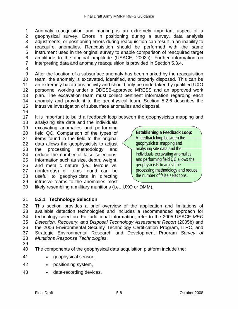
Final Draft Army MMRP RI/FS Guidance
Final Draft October 2008 5-8
Anomaly reacquisition and marking is an extremely important aspect of a 1 geophysical survey. Errors in positioning during a survey, data analysis 2 adjustments, or positioning errors during reacquisition can result in an inability to 3 reacquire anomalies. Reacquisition should be performed with the same 4 instrument used in the original survey to enable comparison of reacquired target 5 amplitude to the original amplitude (USACE, 2003c). Further information on 6 interpreting data and anomaly reacquisition is provided in Section 5.3.4. 7 8 After the location of a subsurface anomaly has been marked by the reacquisition 9 team, the anomaly is excavated, identified, and properly disposed. This can be 10 an extremely hazardous activity and should only be undertaken by qualified UXO 11 personnel working under a DDESB-approved MRESS and an approved work 12 plan. The excavation team must collect pertinent information regarding each 13 anomaly and provide it to the geophysical team. Section 5.2.6 describes the 14 intrusive investigation of subsurface anomalies and disposal. 15 16 It is important to build a feedback loop between the geophysicists mapping and 17 analyzing site data and the individuals 18 excavating anomalies and performing 19 field QC. Comparison of the types of 20 items found in the field to the original 21 data allows the geophysicists to adjust 22 the processing methodology and 23 reduce the number of false selections. 24 Information such as size, depth, weight, 25 and metallic nature (i.e., ferrous vs. 26 nonferrous) of items found can be 27 useful to geophysicists in directing 28 intrusive teams to the anomalies most 29 likely resembling a military munitions (i.e., UXO or DMM). 30
5.2.1 Technology Selection 31 This section provides a brief overview of the application and limitations of 32 available detection technologies and includes a recommended approach for 33 technology selection. For additional information, refer to the 2005 USACE MEC 34 Detection, Recovery, and Disposal Technology Assessment Report (2005b) and 35 the 2006 Environmental Security Technology Certification Program, ITRC, and 36 Strategic Environmental Research and Development Program Survey of 37 Munitions Response Technologies. 38 39 The components of the geophysical data acquisition platform include the: 40
• geophysical sensor, 41 • positioning system, 42 • data-recording devices, 43
Establishing a Feedback Loop: A feedback loop between the geophysicists mapping and analyzing site data and the individuals excavating anomalies and performing field QC allows the geophysicists to adjust the processing methodology and reduce the number of false selections.
Final Draft Army MMRP RI/FS Guidance
Final Draft October 2008 5-9
• electronic and power cables, and 1 • mode of transport. 2
3 Some of these components may be integrated into a single unit by the 4 manufacturer or the contractor during the design of the platform. Important 5 design considerations for the data acquisition platform include the munitions 6 response objectives, ergonomic design, safety, reduction or removal of metal 7 components that are near the geophysical sensor (or the use of nonferrous 8 metals, such as aluminum, for magnetometers), and minimization of the 9 movement of any metal with respect to the geophysical sensor (USACE, 2005b). 10 11 Portable Detection Systems 12 A common method for conducting geophysical surveys is the use of man-13 portable technologies. The production rate for this method is lower than other 14 systems (1–5 acres per day), but man-portable systems are useful in certain 15 terrain (e.g., rough terrain, wooded areas) and under certain circumstances (e.g., 16 small areas). Towed arrays have become popular in open areas and have a 17 higher production rate (5–20 acres per day) based on the speed with which data 18 are collected and the use of multiple detectors (larger footprint). The quality of 19 data and detection depth of ground-based systems are generally superior to 20 other platforms due to the proximity of the detection systems to the ground. 21 22 Airborne Systems / Wide Area Assessments 23 Although not all MRSs are suitable for use of airborne WAA technologies, WAA 24 systems have been evaluated as a regional footprint reduction tool (300–500 25 acres per day), but have limitations due to the inability of the systems to detect 26 small anomalies (e.g., small munitions) from a safe operating altitude. There are 27 also considerably advanced processing procedures required to remove the 28 effects of the fixed-wing or rotary-wing aircraft on the detection system. Many of 29 these technologies need to be flown close to the ground; this can be limited by 30 vegetation (e.g., forests) and extreme topography. Another factor that has limited 31 the popularity of airborne methods is the cost associated with maintaining and 32 operating the aircraft. 33 34 Marine Investigations 35 Perhaps the most challenging aspect of marine investigations is accurately 36 determining the position of one or more submerged detectors. Typically, the 37 conditions in the marine environment (e.g., silt or sand, wave and current action) 38 support burial (i.e., covering) of munitions or their deep penetration and, in many 39 cases, lateral movement of underwater munitions. Analog systems, specifically 40 magnetometers, are preferred for underwater geophysical surveys because the 41 geophysical sensors must be near the bottom of the water to accurately detect 42 deep into the sediments. Positioning is mandatory due to the cost of location 43 identification and recovery of suspect anomalies in the marine environment. To 44 avoid the potential for movement of detected anomalies, any required removal of 45
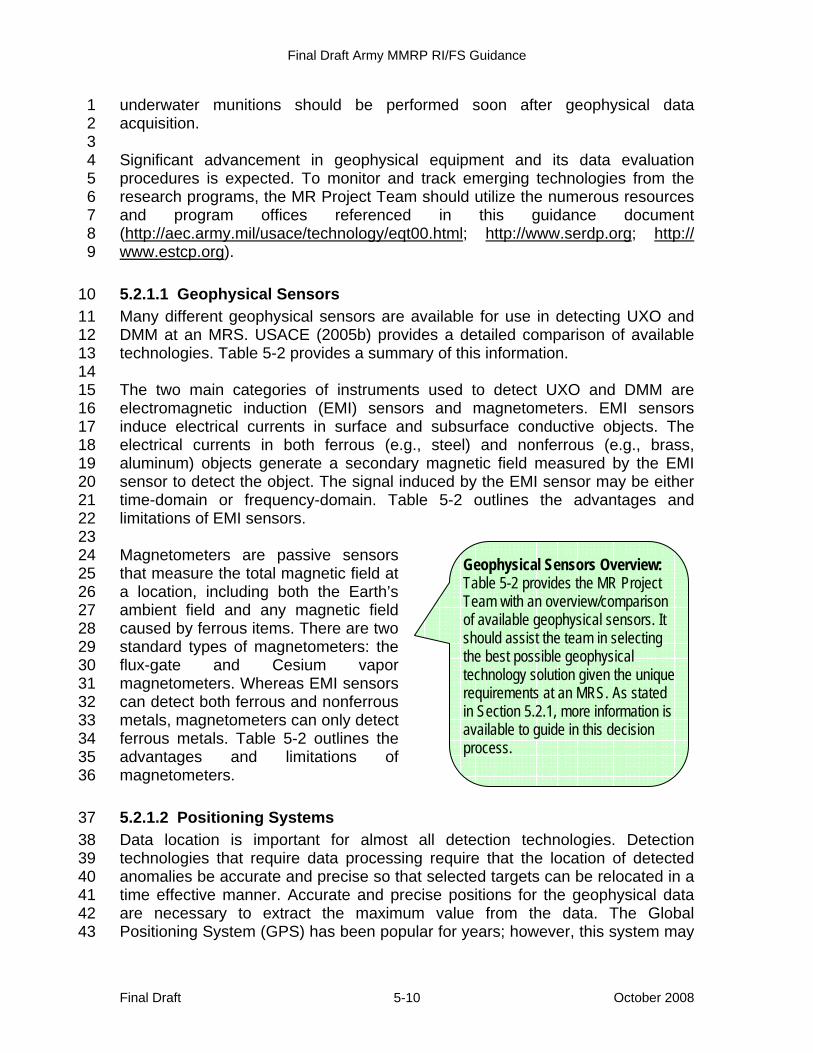
Final Draft Army MMRP RI/FS Guidance
Final Draft October 2008 5-10
underwater munitions should be performed soon after geophysical data 1 acquisition. 2 3 Significant advancement in geophysical equipment and its data evaluation 4 procedures is expected. To monitor and track emerging technologies from the 5 research programs, the MR Project Team should utilize the numerous resources 6 and program offices referenced in this guidance document 7 (http://aec.army.mil/usace/technology/eqt00.html; http://www.serdp.org; http:// 8 www.estcp.org). 9
5.2.1.1 Geophysical Sensors 10 Many different geophysical sensors are available for use in detecting UXO and 11 DMM at an MRS. USACE (2005b) provides a detailed comparison of available 12 technologies. Table 5-2 provides a summary of this information. 13 14 The two main categories of instruments used to detect UXO and DMM are 15 electromagnetic induction (EMI) sensors and magnetometers. EMI sensors 16 induce electrical currents in surface and subsurface conductive objects. The 17 electrical currents in both ferrous (e.g., steel) and nonferrous (e.g., brass, 18 aluminum) objects generate a secondary magnetic field measured by the EMI 19 sensor to detect the object. The signal induced by the EMI sensor may be either 20 time-domain or frequency-domain. Table 5-2 outlines the advantages and 21 limitations of EMI sensors. 22 23 Magnetometers are passive sensors 24 that measure the total magnetic field at 25 a location, including both the Earth’s 26 ambient field and any magnetic field 27 caused by ferrous items. There are two 28 standard types of magnetometers: the 29 flux-gate and Cesium vapor 30 magnetometers. Whereas EMI sensors 31 can detect both ferrous and nonferrous 32 metals, magnetometers can only detect 33 ferrous metals. Table 5-2 outlines the 34 advantages and limitations of 35 magnetometers. 36
5.2.1.2 Positioning Systems 37 Data location is important for almost all detection technologies. Detection 38 technologies that require data processing require that the location of detected 39 anomalies be accurate and precise so that selected targets can be relocated in a 40 time effective manner. Accurate and precise positions for the geophysical data 41 are necessary to extract the maximum value from the data. The Global 42 Positioning System (GPS) has been popular for years; however, this system may 43
Geophysical Sensors Overview: Table 5-2 provides the MR Project Team with an overview/comparison of available geophysical sensors. It should assist the team in selecting the best possible geophysical technology solution given the unique requirements at an MRS. As stated in Section 5.2.1, more information is available to guide in this decision process.
Final Draft Army MMRP RI/FS Guidance
Final Draft October 2008 5-11
have limited application in some areas (e.g., wooded areas with thick canopy). 1 For this reason, a number of other existing positioning systems have been 2 introduced for use during munitions response to MEC. Table 5-3 provides a 3 summary of the detailed analysis of various positioning systems presented by 4 USACE (2005b). 5
5.2.1.3 Data Analysis and Processing 6 In recent years, survey data analysis and processing techniques for use with 7 commercial sensors have been developed that improve detection capabilities 8 and discrimination between MEC (UXO or DMM) and other metallic clutter. 9 These developments have been demonstrated for use with magnetometer data 10 and EMI sensor data. The procedures rely on physics-based models in which 11 estimated model parameters are correlated with target features from actual 12 geophysical sensor data. Those target features include the target’s spatial 13 parameters, such as their location, orientation and depth; the target’s physical 14 parameters, such as their size, shape and density; and the target’s magnetic and 15 electromagnetic properties (USACE, 2005b). 16
5.2.1.3.1 Geophysical Prove-Out 17 Currently, the GPO process consists of designing and planning a GPO, 18 constructing the GPO plot, implementing the prove-out, and reporting the GPO 19 results. This process is under review to increase efficiency, eliminate 20 unnecessary steps, and reduce costs. 21 22 The purposes of a GPO include the following: 23
• Determine if a particular geophysical system works at a particular site. 24 • Determine the optimum geophysical system configuration and standard 25
operating procedures (SOPs) for a particular MRS. 26 • Can prove detection depth capabilities. Note: A large population of data 27
from national test sites and other GPO sites is available. 28 • Demonstrate that the system is meeting typical detection performance 29
capabilities for a given target of interest. 30 • Assure contractor compliance with the contract. 31 • Evaluate the MR Project Team’s data collection, data transfer methods, 32
and data transfer rates. 33 • Establish MRS-specific geophysical data needs and MRS-specific data 34
quality measures and protocols for all work tasks involving geophysics 35 and all work tasks that use geophysical data. 36
• Establish MRS-specific anomaly characteristics for selection criteria. 37 • Demonstrate anomaly resolution procedures to ensure contractor SOPs 38
achieve both munitions response requirements and QA/QC 39 requirements. 40
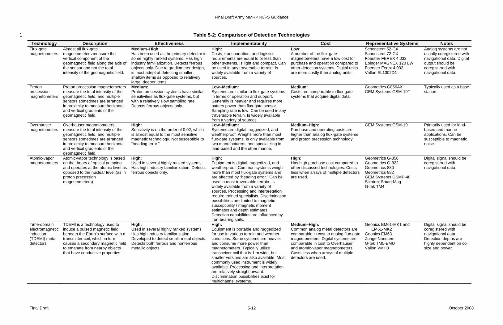
Final Draft Army MMRP RI/FS Guidance
Final Draft October 2008 5-12
Table 5-2: Comparison of Detection Technologies 1
Technology Description Effectiveness Implementability Cost Representative Systems Notes Flux-gate magnetometers
Almost all flux-gate magnetometers measure the vertical component of the geomagnetic field along the axis of the sensor and not the total intensity of the geomagnetic field.
Medium–High: Has been used as the primary detector in some highly ranked systems. Has high industry familiarization. Detects ferrous objects only. Due to gradiometer design, is most adept at detecting smaller, shallow items as opposed to relatively large, deeper items.
High: Costs, transportation, and logistics requirements are equal to or less than other systems. Is light and compact. Can be used in any traversable terrain. Is widely available from a variety of sources.
Low: A number of the flux-gate magnetometers have a low cost for purchase and operation compared to other detection systems. Digital units are more costly than analog units.
Schonstedt 52-CX Schonstedt 72-CX Foerster FEREX 4.032 Ebinger MAGNEX 120 LW Foerster Ferex 4.032 Vallon EL1302D1
Analog systems are not usually coregistered with navigational data. Digital output should be coregistered with navigational data.
Proton precession magnetometers
Proton precession magnetometers measure the total intensity of the geomagnetic field, and multiple sensors sometimes are arranged in proximity to measure horizontal and vertical gradients of the geomagnetic field.
Medium: Proton precession systems have similar sensitivities as flux-gate systems, but with a relatively slow sampling rate. Detects ferrous objects only.
Low–Medium: Systems are similar to flux-gate systems in terms of operation and support. Generally is heavier and requires more battery power than flux-gate sensor. Sampling rate is low. Can be used in any traversable terrain. Is widely available from a variety of sources.
Medium: Costs are comparable to flux-gate systems that acquire digital data.
Geometrics G856AX GEM Systems GSM-19T
Typically used as a base station.
Overhauser magnetometers
Overhauser magnetometers measure the total intensity of the geomagnetic field, and multiple sensors sometimes are arranged in proximity to measure horizontal and vertical gradients of the geomagnetic field.
High: Sensitivity is on the order of 0.02, which is almost equal to the most sensitive magnetic technology. Not susceptible to “heading error.”
Low–Medium: Systems are digital, ruggedized, and weatherproof. Weighs more than most flux-gate systems. Is only available from two manufacturers, one specializing in land-based and the other marine.
Medium–High: Purchase and operating costs are higher than analog flux-gate systems and proton precession technology.
GEM Systems GSM-19 Primarily used for land-based and marine applications. Can be susceptible to magnetic noise.
Atomic-vapor magnetometers
Atomic-vapor technology is based on the theory of optical pumping and operates at the atomic level as opposed to the nuclear level (as in proton precession magnetometers).
High: Used in several highly ranked systems. Has high industry familiarization. Detects ferrous objects only.
High: Equipment is digital, ruggedized, and weatherproof. Common systems weigh more than most flux-gate systems and are affected by “heading error.” Can be used in most traversable terrain. Is widely available from a variety of sources. Processing and interpretation require trained specialists. Discrimination possibilities are limited to magnetic susceptibility / magnetic moment estimates and depth estimates. Detection capabilities are influenced by iron-bearing soils.
High: Has high purchase cost compared to other discussed technologies. Costs less when arrays of multiple detectors are used.
Geometrics G-858 Geometrics G-822 Geometrics 880 Geometrics 882 GEM Systems GSMP-40 Scintrex Smart Mag G-tek TM4
Digital signal should be coregistered with navigational data.
Time-domain electromagnetic induction (TDEMI) metal detectors
TDEMI is a technology used to induce a pulsed magnetic field beneath the Earth’s surface with a transmitter coil, which in turn causes a secondary magnetic field to emanate from nearby objects that have conductive properties.
High: Used in several highly ranked systems. Has high industry familiarization. Developed to detect small, metal objects. Detects both ferrous and nonferrous metallic objects.
High: Equipment is portable and ruggedized for use in various terrain and weather conditions. Some systems are heavier and consume more power than magnetometers. Typically utilize transceiver coil that is 1 m wide, but smaller versions are also available. Most commonly used instrument is widely available. Processing and interpretation are relatively straightforward. Discrimination possibilities exist for multichannel systems.
Medium–High: Common analog metal detectors are comparable in cost to analog flux-gate magnetometers. Digital systems are comparable in cost to Overhauser and atomic-vapor magnetometers. Costs less when arrays of multiple detectors are used.
Geonics EM61-MK1 and EM61-MK2
Geonics EM63 Zonge Nanotem G-tek TM5-EMU Vallon VMH3
Digital signal should be coregistered with navigational data. Detection depths are highly dependent on coil size and power.

Final Draft Army MMRP RI/FS Guidance
Final Draft October 2008 5-13
Technology Description Effectiveness Implementability Cost Representative Systems Notes Frequency-domain electromagnetic induction (FDEMI) metal detectors
FDEMI sensors generate one or more defined frequencies in a continuous mode of operation.
Medium–High: Some digital units are the primary detector in highly ranked systems. Demonstrates capability for detecting small items using handheld unit. Is not optimum for detecting deeply buried objects. Has high industry familiarization. Detects both ferrous and nonferrous metallic objects.
High: Handheld detectors are generally light, compact, and ergonomic. Most are handheld. Is widely available from a variety of sources. Discrimination possibilities exist among some multichannel systems and some handheld systems.
Medium–High: Costs less when arrays of multiple detectors are used. Common handheld metal detectors are much lower cost than digital systems.
Schiebel ANPSS-12 White's All Metals Detector Fisher 1266X Geophex GEM 2 and 3 Geonics EM31 and EM34 Apex Max-Min
Analog systems are not usually coregistered with navigational data. Digital output should be coregistered with navigational data.
Ground penetrating radar (GPR)
GPR works by propagating electromagnetic waves into the ground via an antenna. These transmitted signals are reflected by objects and features that possess contrasts in electrical properties with the surrounding medium.
Low: Is extremely sensitive system that responds to changes in the magnetic, conductive, and dielectric properties of the subsurface. Has a very low success rate as a stand-alone MEC detection system. Detects both metallic and nonmetallic objects, but is susceptible to numerous environmental/geological conditions. Has medium industry familiarization.
Low: Man-portable systems are cumbersome to operate in varying terrain with thick vegetation. Power requirements are higher than most magnetometer and EMI systems. System requires skilled operators.
High: GPR systems are approximately 1.5 to two times the cost of comparable magnetometer and EMI systems.
GSSI SIR2, SIR3, SIR8, SIR10 Sensors and Software Pulse Ekko and Noggin RAMAC Mala
Data output is usually viewed in either transects or two-dimensional time slices. These have not been demonstrated to be as successful as profile outputs.
Sub audio magnetics (SAM)
SAM is a patented methodology by which a total field magnetic sensor is used to simultaneously acquire both magnetic and electromagnetic response of subsurface MEC.
Medium–High: Detects both ferrous and nonferrous metallic objects. Is capable tool for detection of deep MEC. Has low industry familiarization.
Low: Has high data processing requirements. Is only available from one source. Has high power requirements. Has longer than average setup times.
High: Has higher than average operating costs and very low availability.
G-tek SAM Is not commercially available. Has no established track record.
Magnetometer-electromagnetic detection dual sensor systems
These dual sensor systems are expected to be effective in detecting all types of MEC, as magnetometers respond to large deep ferrous targets and EMI sensors respond to nonferrous metallic targets.
High: Detects both ferrous and nonferrous metallic objects. Has medium industry familiarization. Has higher potential for discrimination.
Medium–High: Has high data processing requirements. Is available from few sources.
High: Lower costs can be obtained by using a towed array platform. Has low availability.
GEOCENTERS AETC MTADS
Is available from only a few sources.
Marine side-scan sonar
Side-scan sonar technology uses acoustic (i.e., sound) waves to locate objects and record water bottom structure in a swath on one or both sides of its sensors.
Low: Visualizes shapes of both metallic and nonmetallic objects. Only detects items on surface of water body floor. Has low industry familiarization.
Medium: Requires trained operator, experienced field crew; calm water may be needed. Vegetation can hinder acoustic signal propagation.
High for marine investigations Klein 5500, EdgeTech DF-1000, Triton Elics Sonar Suite, GeoAcoustics, Fishers SSS-100K/600K, Marin Sonic Technologies
Few have applied this technology to the MEC problem.
Airborne multi- or hyper- spectral imagery
This airborne method utilizes unique spectral signatures produced by an item to determine the item composition and size. Multispectral techniques can be used since they provide more information than images from common broadband cameras.
Low: Detects both metallic and nonmetallic objects. Only detects largest MEC. Requires line of sight. Has low industry familiarization. Effectiveness increases when used for WAA in conjunction with other airborne technologies.
Low: Requires aircraft and an experienced pilot. Also requires substantial data processing and management. Is available from few sources.
High: Requires aircraft operation and has high maintenance and data processing costs.
There are many multi-/hyper- spectral imagery providers.
Few have applied these technologies to the MEC problem.
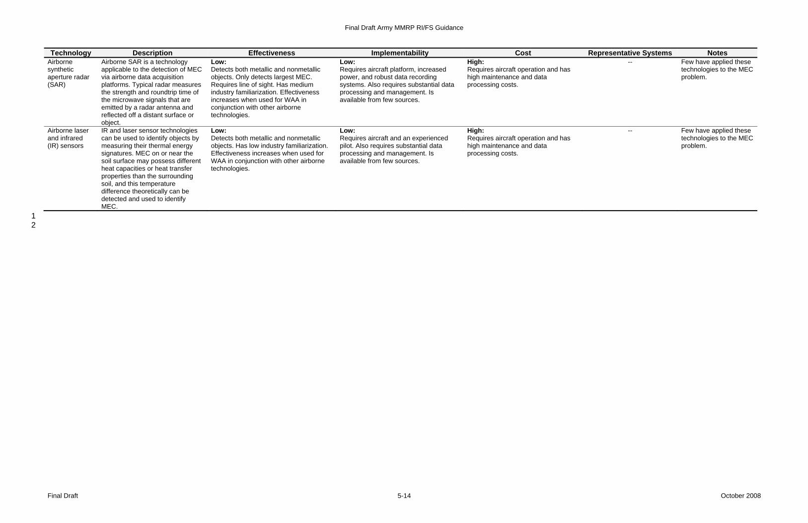
Final Draft Army MMRP RI/FS Guidance
Final Draft October 2008 5-14
Technology Description Effectiveness Implementability Cost Representative Systems Notes Airborne synthetic aperture radar (SAR)
Airborne SAR is a technology applicable to the detection of MEC via airborne data acquisition platforms. Typical radar measures the strength and roundtrip time of the microwave signals that are emitted by a radar antenna and reflected off a distant surface or object.
Low: Detects both metallic and nonmetallic objects. Only detects largest MEC. Requires line of sight. Has medium industry familiarization. Effectiveness increases when used for WAA in conjunction with other airborne technologies.
Low: Requires aircraft platform, increased power, and robust data recording systems. Also requires substantial data processing and management. Is available from few sources.
High: Requires aircraft operation and has high maintenance and data processing costs.
-- Few have applied these technologies to the MEC problem.
Airborne laser and infrared (IR) sensors
IR and laser sensor technologies can be used to identify objects by measuring their thermal energy signatures. MEC on or near the soil surface may possess different heat capacities or heat transfer properties than the surrounding soil, and this temperature difference theoretically can be detected and used to identify MEC.
Low: Detects both metallic and nonmetallic objects. Has low industry familiarization. Effectiveness increases when used for WAA in conjunction with other airborne technologies.
Low: Requires aircraft and an experienced pilot. Also requires substantial data processing and management. Is available from few sources.
High: Requires aircraft operation and has high maintenance and data processing costs.
-- Few have applied these technologies to the MEC problem.
1 2
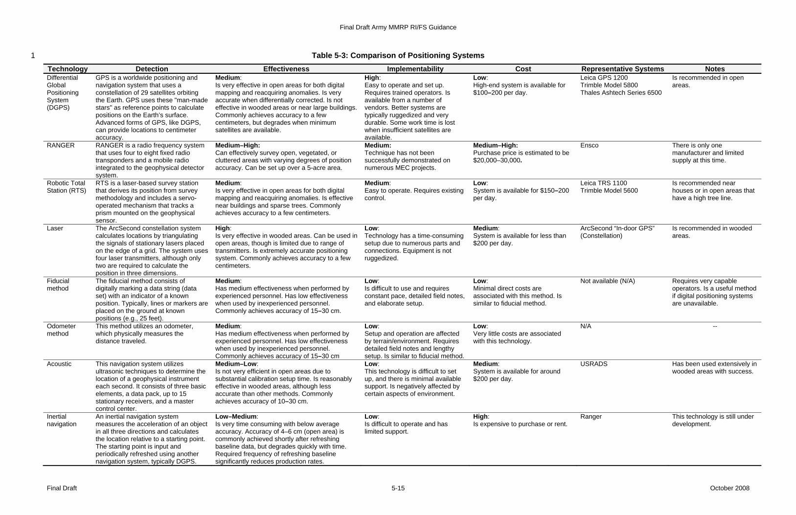
Final Draft Army MMRP RI/FS Guidance
Final Draft October 2008 5-15
Table 5-3: Comparison of Positioning Systems 1
Technology Detection Effectiveness Implementability Cost Representative Systems Notes Differential Global Positioning System (DGPS)
GPS is a worldwide positioning and navigation system that uses a constellation of 29 satellites orbiting the Earth. GPS uses these "man-made stars" as reference points to calculate positions on the Earth’s surface. Advanced forms of GPS, like DGPS, can provide locations to centimeter accuracy.
Medium: Is very effective in open areas for both digital mapping and reacquiring anomalies. Is very accurate when differentially corrected. Is not effective in wooded areas or near large buildings. Commonly achieves accuracy to a few centimeters, but degrades when minimum satellites are available.
High: Easy to operate and set up. Requires trained operators. Is available from a number of vendors. Better systems are typically ruggedized and very durable. Some work time is lost when insufficient satellites are available.
Low: High-end system is available for $100–200 per day.
Leica GPS 1200 Trimble Model 5800 Thales Ashtech Series 6500
Is recommended in open areas.
RANGER RANGER is a radio frequency system that uses four to eight fixed radio transponders and a mobile radio integrated to the geophysical detector system.
Medium–High: Can effectively survey open, vegetated, or cluttered areas with varying degrees of position accuracy. Can be set up over a 5-acre area.
Medium: Technique has not been successfully demonstrated on numerous MEC projects.
Medium–High: Purchase price is estimated to be $20,000–30,000.
Ensco There is only one manufacturer and limited supply at this time.
Robotic Total Station (RTS)
RTS is a laser-based survey station that derives its position from survey methodology and includes a servo-operated mechanism that tracks a prism mounted on the geophysical sensor.
Medium: Is very effective in open areas for both digital mapping and reacquiring anomalies. Is effective near buildings and sparse trees. Commonly achieves accuracy to a few centimeters.
Medium: Easy to operate. Requires existing control.
Low: System is available for $150–200 per day.
Leica TRS 1100 Trimble Model 5600
Is recommended near houses or in open areas that have a high tree line.
Laser The ArcSecond constellation system calculates locations by triangulating the signals of stationary lasers placed on the edge of a grid. The system uses four laser transmitters, although only two are required to calculate the position in three dimensions.
High: Is very effective in wooded areas. Can be used in open areas, though is limited due to range of transmitters. Is extremely accurate positioning system. Commonly achieves accuracy to a few centimeters.
Low: Technology has a time-consuming setup due to numerous parts and connections. Equipment is not ruggedized.
Medium: System is available for less than $200 per day.
ArcSecond “In-door GPS” (Constellation)
Is recommended in wooded areas.
Fiducial method
The fiducial method consists of digitally marking a data string (data set) with an indicator of a known position. Typically, lines or markers are placed on the ground at known positions (e.g., 25 feet).
Medium: Has medium effectiveness when performed by experienced personnel. Has low effectiveness when used by inexperienced personnel. Commonly achieves accuracy of 15–30 cm.
Low: Is difficult to use and requires constant pace, detailed field notes, and elaborate setup.
Low: Minimal direct costs are associated with this method. Is similar to fiducial method.
Not available (N/A) Requires very capable operators. Is a useful method if digital positioning systems are unavailable.
Odometer method
This method utilizes an odometer, which physically measures the distance traveled.
Medium: Has medium effectiveness when performed by experienced personnel. Has low effectiveness when used by inexperienced personnel. Commonly achieves accuracy of 15–30 cm
Low: Setup and operation are affected by terrain/environment. Requires detailed field notes and lengthy setup. Is similar to fiducial method.
Low: Very little costs are associated with this technology.
N/A --
Acoustic This navigation system utilizes ultrasonic techniques to determine the location of a geophysical instrument each second. It consists of three basic elements, a data pack, up to 15 stationary receivers, and a master control center.
Medium–Low: Is not very efficient in open areas due to substantial calibration setup time. Is reasonably effective in wooded areas, although less accurate than other methods. Commonly achieves accuracy of 10–30 cm.
Low: This technology is difficult to set up, and there is minimal available support. Is negatively affected by certain aspects of environment.
Medium: System is available for around $200 per day.
USRADS Has been used extensively in wooded areas with success.
Inertial navigation
An inertial navigation system measures the acceleration of an object in all three directions and calculates the location relative to a starting point. The starting point is input and periodically refreshed using another navigation system, typically DGPS.
Low–Medium: Is very time consuming with below average accuracy. Accuracy of 4–6 cm (open area) is commonly achieved shortly after refreshing baseline data, but degrades quickly with time. Required frequency of refreshing baseline significantly reduces production rates.
Low: Is difficult to operate and has limited support.
High: Is expensive to purchase or rent.
Ranger This technology is still under development.

Final Draft Army MMRP RI/FS Guidance
Final Draft October 2008 5-16
1 EM 1110-1-4009 (USACE, 2007) and Geophysical Prove-Outs for Munitions 2 Response Projects (ITRC, 2004) provide additional information regarding 3 planning and implementing a GPO. Internet hyperlinks to publications that 4 contain discussions on selecting the appropriate geophysical instrument are 5 provided in Appendix D. 6
5.2.2 Survey Approach Decisions 7 Different survey approaches can be used depending on the goals of the RI/FS. 8 Review of the previous studies may provide adequate geophysical information to 9 make appropriate decisions in the FS. If further geophysical investigation is 10 needed, probabilistic survey approaches can be used when the goals are to 11 investigate for UXO or DMM or to look for large objects (e.g., target areas, 12 disposal trenches). Figure 5-3 shows several different survey design approaches 13 that can be used for DGM surveys. Additional guidance for selecting probabilistic 14 survey method of investigation can be found in EM 1110-1-4009. Probabilistic 15 survey designs include the following (USACE, 2007): 16
• Fixed pattern grid method 17 ° In the fixed pattern grid method, grids are laid out in a pattern on a 18
fixed percentage (often 10%) of an area. 19 ° Other more random patterns can provide statistically valid results 20
using fewer grids, so the fixed pattern grid method is not normally 21 used. 22
• Random pattern grid method 23 ° In the random pattern grid method, a statistical approach is used to 24
randomly locate grids throughout an area. The total area to be 25 investigated must first be determined using a statistical tool, such 26 as the UXO Estimator (see Section 5.2.3). Grid size and shape are 27 then determined using the site terrain, vegetation, and geophysical 28 instrument that will be used. Grids are typically square or 29 rectangular and may be as small as 2,500 square feet or as large 30 as 1 hectare. The size and shape of the grids may vary. 31
° Use of a purely random pattern is not recommended because it 32 leaves the possibility that large areas that were not investigated 33 may contain UXO or DMM. 34
• Hybrid pattern grid method 35 ° In the hybrid pattern grid method, method grids to be investigated 36
are placed randomly (as in the random pattern grid method). 37 However, approximately 20% more grids are added in biased 38 locations to fill in data gaps. 39
° The hybrid pattern grid method approach ensures that an area 40 known to contain MEC receives more thorough coverage. 41

Final Draft Army MMRP RI/FS Guidance
Final Draft October 2008 5-17
• Radial 1 ° In a radial path, a grid pattern is walked radiating out from a single 2
point. 3 ° The radial path approach ensures that an area known to contain 4
MEC receives more thorough coverage. 5 • Transects 6
° During a geophysical transect investigation, a geophysical sensor is 7 walked over lines that are typically evenly spaced apart. This is 8 similar to a 100% design, but the line spacing is often much greater 9 with a transect design. 10
° Use of transects is a good approach to characterize areas and 11 begin to define the boundaries of areas where MEC (UXO or DMM) 12 may be present. Transects can be considered as very narrow, fixed 13 pattern grids. Typically, transects are used at sites with easy terrain 14 and vegetation. 15
• Cross hatch transects 16 o Like a transect investigation, a geophysical sensor is walked in 17
straight lines across a site and then repeated at a 90-degree angle 18 from the original transects. 19
• Full coverage 20 o Like a transect investigation, a geophysical sensor is walked over 21
lines that are typically evenly spaced apart. These are spaced 22 closely together to obtain 100% coverage. 23
• Meandering paths 24 ° When using meandering paths, a geophysical instrument is 25
integrated with a navigation instrument, typically DGPS, and the 26 geophysical team walks a “meandering” path across an MRS. The 27 team records geophysical data until the total area geophysically 28 mapped equals the area that would have been required if sampling 29 grids were used. 30
° Use of meandering paths is a good survey approach at MRSs with 31 difficult vegetation and terrain because it does not require 32 vegetation removal and the geophysical survey cost is greatly 33 reduced. 34
35
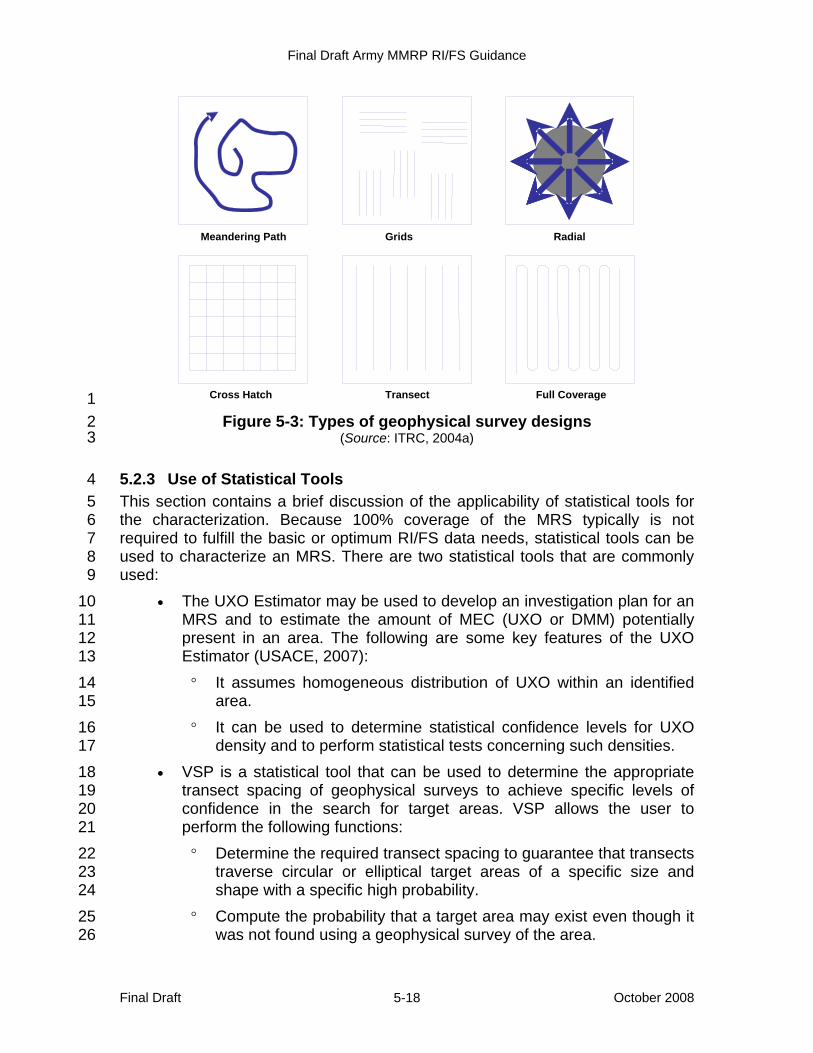
Final Draft Army MMRP RI/FS Guidance
Final Draft October 2008 5-18
1 Figure 5-3: Types of geophysical survey designs 2
(Source: ITRC, 2004a) 3
5.2.3 Use of Statistical Tools 4 This section contains a brief discussion of the applicability of statistical tools for 5 the characterization. Because 100% coverage of the MRS typically is not 6 required to fulfill the basic or optimum RI/FS data needs, statistical tools can be 7 used to characterize an MRS. There are two statistical tools that are commonly 8 used: 9
• The UXO Estimator may be used to develop an investigation plan for an 10 MRS and to estimate the amount of MEC (UXO or DMM) potentially 11 present in an area. The following are some key features of the UXO 12 Estimator (USACE, 2007): 13 ° It assumes homogeneous distribution of UXO within an identified 14
area. 15 ° It can be used to determine statistical confidence levels for UXO 16
density and to perform statistical tests concerning such densities. 17 • VSP is a statistical tool that can be used to determine the appropriate 18
transect spacing of geophysical surveys to achieve specific levels of 19 confidence in the search for target areas. VSP allows the user to 20 perform the following functions: 21 ° Determine the required transect spacing to guarantee that transects 22
traverse circular or elliptical target areas of a specific size and 23 shape with a specific high probability. 24
° Compute the probability that a target area may exist even though it 25 was not found using a geophysical survey of the area. 26
Meandering Path Grids Radial
Cross Hatch Transect Full Coverage
Final Draft Army MMRP RI/FS Guidance
Final Draft October 2008 5-19
° Approximate the probability that a target area of a specific size and 1 shape would have been found during a geophysical survey if 2 straight-line or meandering transects were used. 3
° VSP is also a useful statistical tool to evaluate MC (e.g., to quantify 4 the uncertainty for MC, make inferences about MC to support 5 decisions, quantify number of MC samples to be collected). 6
7 VSP may be used on MRSs that are known to contain areas with a high density 8 of UXO whose locations may not be known, while the UXO Estimator may be 9 used on MRSs assumed to have a homogeneous MEC distribution. Additional 10 guidance on statistical investigation (sampling) approaches is available in EM 11 1110-1-4009 (USACE, 2007). The UXO Estimator is available from the USACE 12 EM CX. VSP can be downloaded from http://dqo.pnl.gov/ vsp/vspdesc.htm. 13
5.2.4 Phenomenological Geophysical Analysis 14 Phenomenological evaluation of an MRS can provide valuable information about 15 the appropriate technology and survey design for use at an MRS. Background 16 geophysical surveys can be used to determine the level of background noise 17 common at an MRS for use in evaluating and selecting anomalies for 18 investigation. Phenomenological factors include: 19
• munitions type, orientation, and potential depth; 20 • topography; 21 • soil and rock types; 22 • vegetation; and 23 • cultural features (e.g., overhead power lines, underground utilities, 24
buildings). 25 26 The basic premise for considering phenomenology is that the geologic and 27 cultural makeup of the MRS are primary influences on what the geophysical 28 sensor measures. The phenomenological evaluation considers a variety of 29 factors during the sensor selection process, including physical characteristics of 30 the MRS, geophysical properties of the soil or rock, types of munitions, and 31 potential depth of subsurface munitions (Simms et al., 2004). 32 33 The USACE’s Engineering Research and Development Center (ERDC) 34 Geotechnical and Structures Laboratory has developed a six-step process to 35 evaluate phenomenological aspects of a site (Simms et al., 2004). Although this 36 evaluation is not routine procedure for an RI due to cost constraints and data 37 availability, it could provide valuable information if data are available and cost 38 constraints are removed. 39
Final Draft Army MMRP RI/FS Guidance
Final Draft October 2008 5-20
5.2.5 Anomaly Discrimination and Data Interpretation 1 In recent years, survey data analysis and processing techniques for use with 2 commercial sensors have been developed that improve detection capabilities 3 and discrimination between MEC (UXO or DMM) and other metallic clutter. 4 These developments have been demonstrated for use with magnetometer data 5 and EMI sensor data. The procedures rely on physics-based models in which 6 estimated model parameters are correlated with target (anomaly) features from 7 actual geophysical sensor data. Those target features include the target’s spatial 8 parameters, such as location, orientation, and depth; the target’s physical 9 parameters, such as size, shape, and density; and the target’s magnetic and 10 electromagnetic properties. 11 12 Discrimination specifically is defined for 13 munitions responses to MEC as the 14 ability to distinguish between hazardous 15 MEC and other pieces of metal (e.g., 16 nails, horseshoes, cans, pipes). This 17 process is performed by determining (or 18 measuring) the geophysical 19 characteristics of a subsurface item 20 (anomaly) and comparing those 21 characteristics to modeled or actual 22 results (e.g., the GPO). The primary 23 variables defining the geophysical 24 characteristics are the shape, orientation, distance and direction, and material 25 composition of an item, as well as the ambient magnetic and/or electromagnetic 26 field. Variations in these parameters have the potential to change the 27 geophysical signature. Additionally, a detected anomaly that is large and deep 28 can have a similar signal intensity to one that is small and shallow. The primary 29 objective of discrimination is to reduce the number of unnecessary intrusive 30 investigations and, thus, the cost of investigating an MRS. 31
5.2.6 Anomaly Investigation 32 Once anomalies are selected, intrusive investigations are conducted to identify 33 the source of selected anomalies. Anomalies may be excavated using 34 mechanical or manual methods. Table 5-4 provides a summary of the detailed 35 analysis of various anomaly investigation systems presented by the USACE 36 (2005b). 37 38 Evacuations of portions of a surrounding community may be necessary to 39 minimize risk during intrusive investigations. As outlined in the MRESS and work 40 plan, an EZ is established to ensure that nonessential personnel are protected 41 from both intentional and unintentional detonations. The design of EZs is detailed 42 in DDESB TP Number 16 (2007). DDESB-approved engineering controls (ECs) 43 can often be used to decrease the size of the exclusion zone (EZ) and DoD 44 6055.9-STD, Chapter 12. EM 1110-1-4009 details the application of these 45
Anomaly Discrimination: The accuracy of discrimination is the focus of many ongoing technology demonstration projects. Regulatory support of this is limited, and site-specific demonstrations of discrimination likely are required to gain stakeholder acceptance of discrimination.
Final Draft Army MMRP RI/FS Guidance
Final Draft October 2008 5-21
controls (USACE, 2007). Evacuations involving residents or nearby workers are 1 coordinated with state or local relocation officials, as required by NCP Section 2 300.415(f). 3 4 Recovered MEC are normally destroyed in place or on site. Under certain and 5 limited conditions, MEC may be transported off site for destruction. The risk 6 associated with the disposal operation, as determined by MRS site-specific 7 characteristics and the nature of the MEC recovered, guides the disposition 8 decision. Technical Manual (TM) 60A-1-1-31 Explosive Ordnance Disposal (U.S. 9 Army, 1999) provides additional information on MEC disposal operations. 10 11 Although, EOD will respond to explosives or munitions emergencies that may 12 occur during a munitions response to MEC, EOD units do not normally support 13 such planned responses. Coordination with the responsible EOD unit prior to 14 initiating activities munitions response actions that require an DDESB-required 15 submission is recommended. 16 17 Additional considerations include the 18 inspection, reinspection, certification, 19 verification, documentation, and 20 subsequent disposal of MPPEH 21 discovered during the intrusive 22 investigations. (See DoD Instruction 23 4140.62 and EM 1110-1-4009). 24 25 Table 5-5 provides disposal options 26 identified by the USACE (2005b). The 27 table divides technologies into two 28 sections: (1) treatment of MEC and (2) 29 disposal of MEC residue and scrap. 30 Residue treatment technologies eliminate 31 explosives from metallic MEC components. 32
5.3 Munitions Constituents Characterization 33 Characterization of MC-related contamination is similar to characterization of 34 environmental contamination (i.e., HTRW) because it involves analytical 35 sampling of soil, vadose zone, sediment, groundwater, and surface water to 36 evaluate the nature and extent of MC. As with HTRW, the nature and extent of 37 MC are used to refine location-specific ARARs, define the risk to human health 38 and the environment through the preparation of a baseline risk assessment, and 39 aid in the development of remedial alternatives. MC may be found in 40 concentrations high enough to pose an explosive hazard. When MC are 41 determined to pose an explosive hazard, they are considered to be MEC, and 42 protective measures, including alternate sampling approaches, must be 43 implemented to ensure the 44
Excavation/Disposal Technologies: Table 5-4 and Table 5-5 provide the RPM and MR Project Team with an overview/comparison of available excavation and disposal technologies. These tables should assist the team in selecting the best possible excavation/disposal technology solution given the unique requirements of a munitions response.
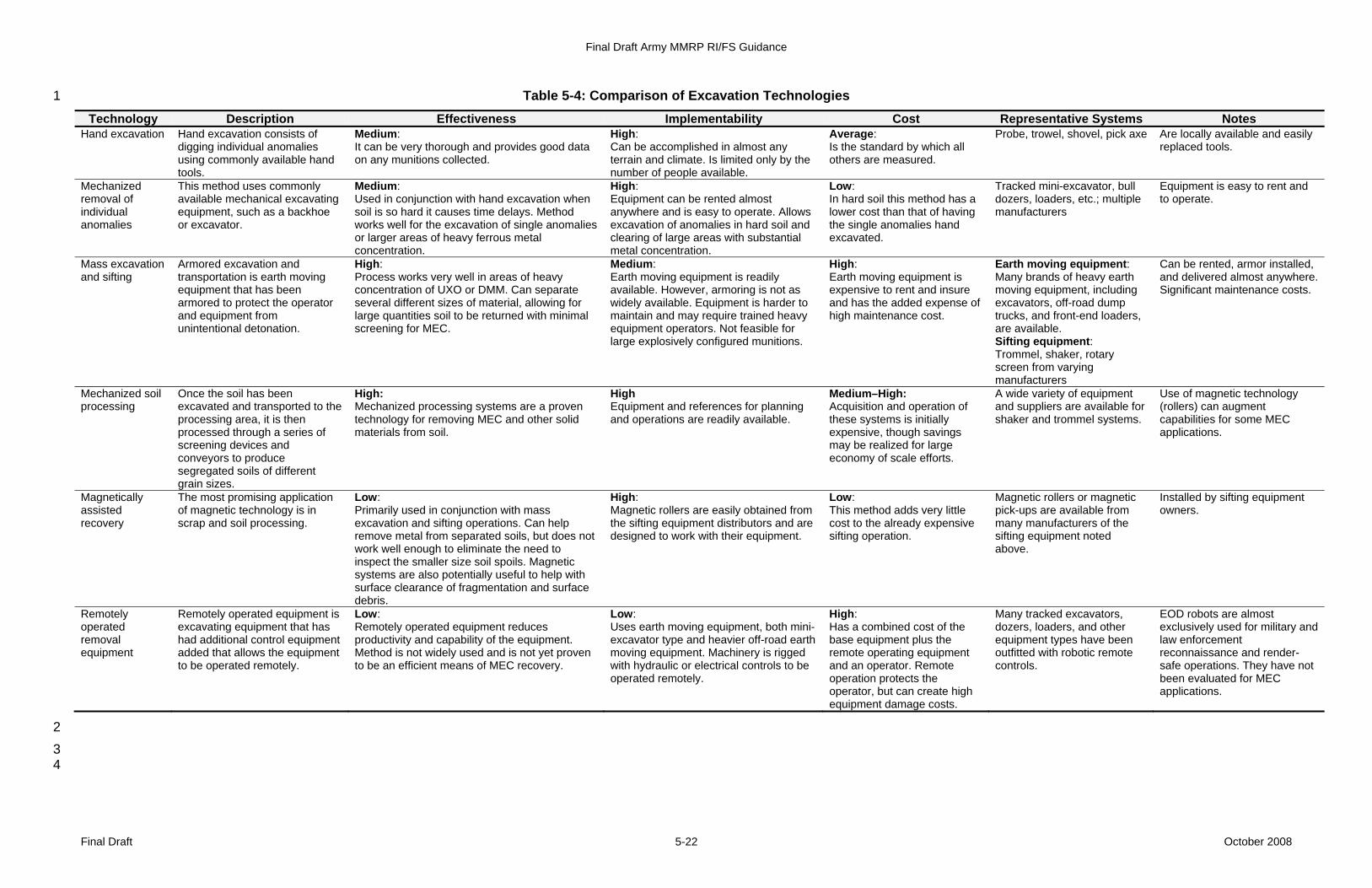
Final Draft Army MMRP RI/FS Guidance
Final Draft October 2008 5-22
Table 5-4: Comparison of Excavation Technologies 1
Technology Description Effectiveness Implementability Cost Representative Systems Notes Hand excavation Hand excavation consists of
digging individual anomalies using commonly available hand tools.
Medium: It can be very thorough and provides good data on any munitions collected.
High: Can be accomplished in almost any terrain and climate. Is limited only by the number of people available.
Average: Is the standard by which all others are measured.
Probe, trowel, shovel, pick axe Are locally available and easily replaced tools.
Mechanized removal of individual anomalies
This method uses commonly available mechanical excavating equipment, such as a backhoe or excavator.
Medium: Used in conjunction with hand excavation when soil is so hard it causes time delays. Method works well for the excavation of single anomalies or larger areas of heavy ferrous metal concentration.
High: Equipment can be rented almost anywhere and is easy to operate. Allows excavation of anomalies in hard soil and clearing of large areas with substantial metal concentration.
Low: In hard soil this method has a lower cost than that of having the single anomalies hand excavated.
Tracked mini-excavator, bull dozers, loaders, etc.; multiple manufacturers
Equipment is easy to rent and to operate.
Mass excavation and sifting
Armored excavation and transportation is earth moving equipment that has been armored to protect the operator and equipment from unintentional detonation.
High: Process works very well in areas of heavy concentration of UXO or DMM. Can separate several different sizes of material, allowing for large quantities soil to be returned with minimal screening for MEC.
Medium: Earth moving equipment is readily available. However, armoring is not as widely available. Equipment is harder to maintain and may require trained heavy equipment operators. Not feasible for large explosively configured munitions.
High: Earth moving equipment is expensive to rent and insure and has the added expense of high maintenance cost.
Earth moving equipment: Many brands of heavy earth moving equipment, including excavators, off-road dump trucks, and front-end loaders, are available. Sifting equipment: Trommel, shaker, rotary screen from varying manufacturers
Can be rented, armor installed, and delivered almost anywhere. Significant maintenance costs.
Mechanized soil processing
Once the soil has been excavated and transported to the processing area, it is then processed through a series of screening devices and conveyors to produce segregated soils of different grain sizes.
High: Mechanized processing systems are a proven technology for removing MEC and other solid materials from soil.
High Equipment and references for planning and operations are readily available.
Medium–High: Acquisition and operation of these systems is initially expensive, though savings may be realized for large economy of scale efforts.
A wide variety of equipment and suppliers are available for shaker and trommel systems.
Use of magnetic technology (rollers) can augment capabilities for some MEC applications.
Magnetically assisted recovery
The most promising application of magnetic technology is in scrap and soil processing.
Low: Primarily used in conjunction with mass excavation and sifting operations. Can help remove metal from separated soils, but does not work well enough to eliminate the need to inspect the smaller size soil spoils. Magnetic systems are also potentially useful to help with surface clearance of fragmentation and surface debris.
High: Magnetic rollers are easily obtained from the sifting equipment distributors and are designed to work with their equipment.
Low: This method adds very little cost to the already expensive sifting operation.
Magnetic rollers or magnetic pick-ups are available from many manufacturers of the sifting equipment noted above.
Installed by sifting equipment owners.
Remotely operated removal equipment
Remotely operated equipment is excavating equipment that has had additional control equipment added that allows the equipment to be operated remotely.
Low: Remotely operated equipment reduces productivity and capability of the equipment. Method is not widely used and is not yet proven to be an efficient means of MEC recovery.
Low: Uses earth moving equipment, both mini-excavator type and heavier off-road earth moving equipment. Machinery is rigged with hydraulic or electrical controls to be operated remotely.
High: Has a combined cost of the base equipment plus the remote operating equipment and an operator. Remote operation protects the operator, but can create high equipment damage costs.
Many tracked excavators, dozers, loaders, and other equipment types have been outfitted with robotic remote controls.
EOD robots are almost exclusively used for military and law enforcement reconnaissance and render-safe operations. They have not been evaluated for MEC applications.
2 3
4
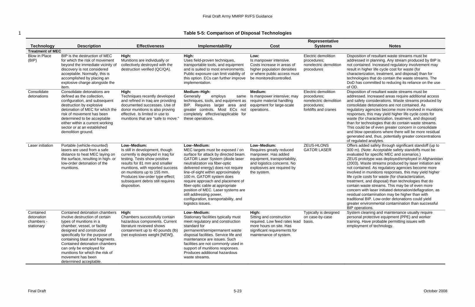
Final Draft Army MMRP RI/FS Guidance
Final Draft October 2008 5-23
Table 5-5: Comparison of Disposal Technologies 1
Technology Description Effectiveness Implementability Cost Representative
Systems Notes Treatment of MEC Blow in Place (BIP)
BIP is the destruction of MEC for which the risk of movement beyond the immediate vicinity of discovery is not considered acceptable. Normally, this is accomplished by placing an explosive charge alongside the item.
High: Munitions are individually or collectively destroyed with the destruction verified (QC/QA).
High: Uses field-proven techniques, transportable tools, and equipment and is suited to most environments. Public exposure can limit viability of this option. ECs can further improve implementation.
Low: Is manpower intensive. Costs increase in areas of higher population densities or where public access must be monitored/controlled.
Electric demolition procedures; nonelectric demolition procedures
Disposition of resultant waste streams must be addressed in planning. Any stream produced by BIP is not contained. Increased regulatory involvement may result in higher life cycle cost for waste (for characterization, treatment, and disposal) than for technologies that do contain the waste streams. The DoD has committed to reducing its reliance on the use of OD.
Consolidate detonations
Consolidate detonations are defined as the collection, configuration, and subsequent destruction by explosive detonation of MEC for which the risk of movement has been determined to be acceptable either within a current working sector or at an established demolition ground.
High: Techniques recently developed and refined in Iraq are providing documented successes. Use of donor munitions is also proving effective. Is limited in use to munitions that are “safe to move.”
Medium–High: Generally employs same techniques, tools, and equipment as BIP. Requires larger area and greater controls. Most ECs not completely effective/applicable for these operations.
Medium: Is manpower intensive; may require material handling equipment for large-scale operations.
Electric demolition procedures; nonelectric demolition procedures; forklifts and cranes
Disposition of resultant waste streams must be addressed. Increased areas require additional access and safety considerations. Waste streams produced by consolidate detonations are not contained. As regulatory agencies become more involved in munitions responses, this may yield higher life cycle costs for waste (for characterization, treatment, and disposal) than for technologies that do contain waste streams. This could be of even greater concern in consolidate and blow operations where there will be more residual generated and, thus, potentially greater concentrations of regulated analytes.
Laser initiation Portable (vehicle-mounted) lasers are used from a safe distance to heat MEC laying on the surface, resulting in high- or low-order detonation of the munitions.
Low–Medium: Is still in development, though currently is deployed in Iraq for testing. Tests show positive results for 81 mm and smaller munitions, with reported success on munitions up to 155 mm. Produces low-order type effect; subsequent debris still requires disposition.
Low–Medium: MEC targets must be exposed / on surface for attack by directed beam. GATOR Laser System (diode laser neutralization via fiber-optic delivered energy) does not require line-of-sight within approximately 100 m. GATOR system does require approach and placement of fiber-optic cable at appropriate position of MEC. Laser systems are still addressing power, configuration, transportability, and logistics issues.
Low–Medium: Requires greatly reduced manpower. Has added equipment, transportability, and logistics concerns. No explosives are required by the system.
ZEUS-HLONS GATOR LASER
Offers added safety through significant standoff (up to 300 m). (Note: Acceptable safety standoffs must be evaluated for specific MEC and scenarios.) ZEUS prototype was deployed/employed in Afghanistan (2003). Waste streams produced by laser initiation are not contained. As regulatory agencies become more involved in munitions responses, this may yield higher life cycle costs for waste (for characterization, treatment, and disposal) than technologies that do contain waste streams. This may be of even more concern with laser initiated detonation/deflagration, as residual contamination may be higher than with traditional BIP. Low-order detonations could yield greater environmental contamination than successful BIP operations.
Contained detonation chambers - stationary
Contained detonation chambers involve destruction of certain types of munitions in a chamber, vessel, or facility designed and constructed specifically for the purpose of containing blast and fragments. Contained detonation chambers can only be employed for munitions for which the risk of movement has been determined acceptable.
High: Chambers successfully contain hazardous components. Current literature reviewed shows containment up to 40 pounds (lb) (net explosives weight [NEW]).
Low–Medium: Stationary facilities typically must meet regulatory and construction standard for permanent/semipermanent waste disposal facilities. Service life and maintenance are issues. Such facilities are not commonly used in support of munitions responses. Produces additional hazardous waste streams.
High: Sitting and construction required. Low feed rates lead more hours on site. Has significant requirements for maintenance of system.
Typically is designed on case-by-case basis.
System cleaning and maintenance usually require personal protective equipment (PPE) and worker training. Have probable permitting issues with employment of technology.
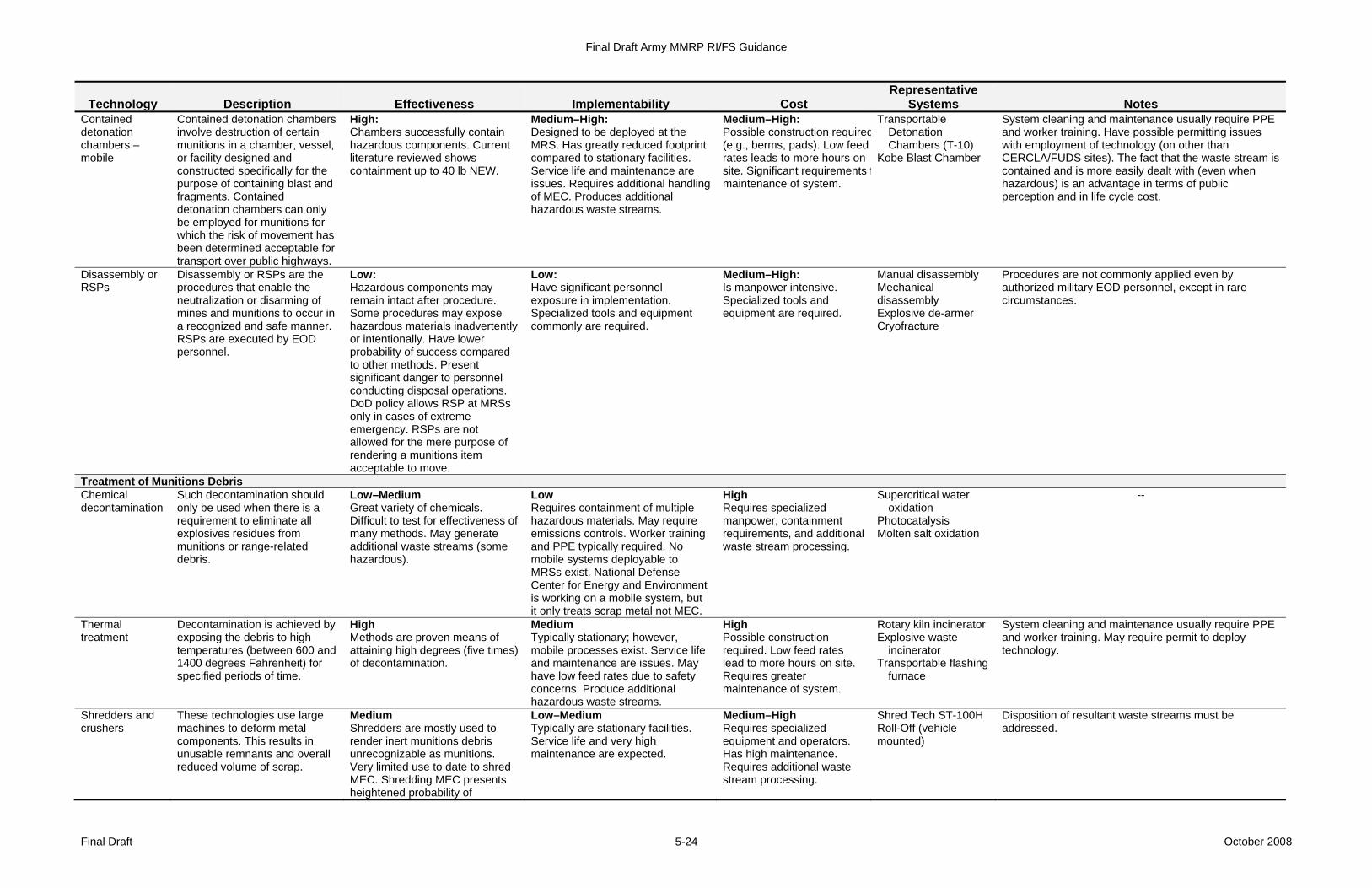
Final Draft Army MMRP RI/FS Guidance
Final Draft October 2008 5-24
Technology Description Effectiveness Implementability Cost Representative
Systems Notes Contained detonation chambers – mobile
Contained detonation chambers involve destruction of certain munitions in a chamber, vessel, or facility designed and constructed specifically for the purpose of containing blast and fragments. Contained detonation chambers can only be employed for munitions for which the risk of movement has been determined acceptable for transport over public highways.
High: Chambers successfully contain hazardous components. Current literature reviewed shows containment up to 40 lb NEW.
Medium–High: Designed to be deployed at the MRS. Has greatly reduced footprint compared to stationary facilities. Service life and maintenance are issues. Requires additional handling of MEC. Produces additional hazardous waste streams.
Medium–High: Possible construction required(e.g., berms, pads). Low feed rates leads to more hours on site. Significant requirements fmaintenance of system.
Transportable Detonation Chambers (T-10)
Kobe Blast Chamber
System cleaning and maintenance usually require PPE and worker training. Have possible permitting issues with employment of technology (on other than CERCLA/FUDS sites). The fact that the waste stream is contained and is more easily dealt with (even when hazardous) is an advantage in terms of public perception and in life cycle cost.
Disassembly or RSPs
Disassembly or RSPs are the procedures that enable the neutralization or disarming of mines and munitions to occur in a recognized and safe manner. RSPs are executed by EOD personnel.
Low: Hazardous components may remain intact after procedure. Some procedures may expose hazardous materials inadvertently or intentionally. Have lower probability of success compared to other methods. Present significant danger to personnel conducting disposal operations. DoD policy allows RSP at MRSs only in cases of extreme emergency. RSPs are not allowed for the mere purpose of rendering a munitions item acceptable to move.
Low: Have significant personnel exposure in implementation. Specialized tools and equipment commonly are required.
Medium–High: Is manpower intensive. Specialized tools and equipment are required.
Manual disassembly Mechanical disassembly Explosive de-armer Cryofracture
Procedures are not commonly applied even by authorized military EOD personnel, except in rare circumstances.
Treatment of Munitions Debris Chemical decontamination
Such decontamination should only be used when there is a requirement to eliminate all explosives residues from munitions or range-related debris.
Low–Medium Great variety of chemicals. Difficult to test for effectiveness of many methods. May generate additional waste streams (some hazardous).
Low Requires containment of multiple hazardous materials. May require emissions controls. Worker training and PPE typically required. No mobile systems deployable to MRSs exist. National Defense Center for Energy and Environment is working on a mobile system, but it only treats scrap metal not MEC.
High Requires specialized manpower, containment requirements, and additional waste stream processing.
Supercritical water oxidation
Photocatalysis Molten salt oxidation
--
Thermal treatment
Decontamination is achieved by exposing the debris to high temperatures (between 600 and 1400 degrees Fahrenheit) for specified periods of time.
High Methods are proven means of attaining high degrees (five times) of decontamination.
Medium Typically stationary; however, mobile processes exist. Service life and maintenance are issues. May have low feed rates due to safety concerns. Produce additional hazardous waste streams.
High Possible construction required. Low feed rates lead to more hours on site. Requires greater maintenance of system.
Rotary kiln incinerator Explosive waste
incinerator Transportable flashing
furnace
System cleaning and maintenance usually require PPE and worker training. May require permit to deploy technology.
Shredders and crushers
These technologies use large machines to deform metal components. This results in unusable remnants and overall reduced volume of scrap.
Medium Shredders are mostly used to render inert munitions debris unrecognizable as munitions. Very limited use to date to shred MEC. Shredding MEC presents heightened probability of
Low–Medium Typically are stationary facilities. Service life and very high maintenance are expected.
Medium–High Requires specialized equipment and operators. Has high maintenance. Requires additional waste stream processing.
Shred Tech ST-100H Roll-Off (vehicle mounted)
Disposition of resultant waste streams must be addressed.
Final Draft Army MMRP RI/FS Guidance
Final Draft October 2008 5-25
Technology Description Effectiveness Implementability Cost Representative
Systems Notes accidental detonation. Residue typically still requires additional treatment to achieve higher decontamination levels.
1 2 3 4 5 6 7 8 9 10 11 12 13 14 15 16 17 18 19 20
Final Draft Army MMRP RI/FS Guidance
Final Draft October 2008 5-26
safety of personnel. High concentrations of MC are not expected to be 1 encountered on ranges. Such concentrations could be found at munitions 2 operating facilities (e.g., a melt-out facility, production facility), including in settling 3 ponds and drains. 4 5 MC contamination can result from corrosion of munitions (e.g., UXO, DMM) or 6 from low-order detonations. In a low-order detonation, a munitions item's filler 7 may be scattered over portions of a firing range as constituents or partially 8 encased in the remains of the delivery system. This results in a complex source 9 term that is not amenable to simple evaluation (Brannon et al., 1999). 10 11 Specific MC sampling requirements for an RI/FS are determined on a MRS-12 specific basis by the MR Project Team through the TPP process and the 13 development of a CSM. For additional information on MC characterization 14 requirements, see the EPA’s 1988 Guidance on Conducting Remedial 15 Investigations and Feasibility Studies under CERCLA, USACE's 1994 16 Engineering and Design - Technical Guidelines for Hazardous and Toxic Waste 17 Treatment and Cleanup Activities (EM 1110-1-502), Military Munitions Response 18 Process (EP 1110-1-18) (USACE, 2002), and Engineering and Design – Military 19 Munitions Response Actions (EM 1110-1-4009) (USACE, 2007). MC 20 characterization sampling approaches are addressed in the following sections. 21
5.3.1 Representative Soil Sampling Methods 22 The environmental characteristics of MC in soil indicate that they are extremely 23 heterogeneous in spatial distribution. Secondary MC contamination on testing 24 and training ranges is generally the result of releasing a low-order detonation that 25 exposes a munitions filler. The distribution of MC in soil depends on the degree 26 of combustion and the condition of the munitions item that experienced a low-27 order detonation. Concentrations may range from nondetectable levels (less than 28 0.5 parts per million [ppm]) to percent levels (greater than 10,000 ppm) for 29 samples collected within several feet of each other. At locations used for OB/OD, 30 MC-related contamination can vary greatly (from nonexistent to the presence of 31 chunks of explosive filler). Analysis of the concentration of explosive MC-related 32 contamination is needed to determine whether MC pose an explosive hazard 33 because the type and level of MC-related contamination that can pose an 34 explosive hazard vary greatly. When operating in areas known to pose an 35 explosive hazard, a safety analysis is needed for materials handling equipment to 36 prevent initiating forces that could propagate a detonation throughout the soil 37 mass (Crockett et al., 1998). 38 39 One key aspect to characterizing soils for lead or other MC at a small arms range 40 is reaching consensus on whether to sieve the soil samples prior to analysis. 41 One of the primary reasons to sieve is to remove bullet fragments. Retaining 42 bullet fragments yields a higher concentration of lead; however, the lead in the 43 fragments is not readily available to receptors. 44 45
Final Draft Army MMRP RI/FS Guidance
Final Draft October 2008 5-27
In some locations, native or anthropogenic background concentrations of metals, 1 perchlorate, or PAHs may exceed non-site-specific risk-based screening levels or 2 regulatory limits that are used commonly for screening purposes or response 3 action decision-making. If these parameters are analyzed and no appropriate 4 regional or MRS-specific background data are available for the MRS, background 5 samples should be collected and analyzed. Some available resources for 6 background condition evaluation include the following (USACE, 2007): 7
• Guidance for Environmental Background Concentration Analysis 8 Volume I: Soil (NAVFAC UG-2049-ENV, April 2002) 9 https://portal.navfac.navy.mil/ 10
• Guidance for Environmental Background Concentration Analysis 11 Volume II: Sediment (NAVFAC UG-2054-ENV, April 2003) 12 https://portal.navfac.navy .mil/ 13
• Guidance for Environmental Background Concentration Analysis 14 Volume III: Groundwater (NAVFAC UG-2059-ENV, April 2004) 15 https://portal.navfac .navy.mil/ 16
• Guidance for Comparing Background and Chemical Concentrations in 17 Soil for CERCLA Sites (EPA 540-R-01-003 OSWER 9285.7-41, 18 September 2002) http://www.epa.gov/oswer/riskassessment/pdf/ 19 background.pdf 20
• Environmental Quality – Environmental Statistics. (USACE EM 1110-1-21 4014, January 2008) http://www.usace.army.mil/publications/eng-22 manuals/em1110-1-4014/entire.pdf 23
• Data Quality Assessment: Statistical Methods for Practitioners. (EPA 24 QA/G-9S, February 2006) http://www.epa.gov/quality1/qs-docs/g9s-25 final.pdf 26
27 The Cold Regions Research Engineering Laboratory (CRREL), a USACE ERDC 28 laboratory, has conducted numerous studies to determine the best means to 29 collect a representative sample. These studies have been conducted at primarily 30 active and BRAC sites as part of a research and development (R&D) effort 31 (Jenkins et al., 1996; Thiboutot et al., 2002). Their current recommendations are 32 documented in full in the Field Analytic Technologies Encyclopedia (FATE) 33 Explosives Module located at http://clu-in.org/char/technologies/exp.cfm and in 34 Appendix A of SW8330B located at http://www.epa.gov/epaoswer/ 35 hazwaste/test/new-meth.htm. 36
5.3.2 Analytical Methods 37 Analytical methods for MC should be based on the munitions-related activities, 38 including the types of munitions involved and their fills, conducted at an MRS. 39 Some of the more common MC include nitrogen-based explosives, perchlorate, 40 white phosphorus, agent breakdown products, CWM agents, and heavy metals. 41 Metals at some quantity are found in all cased military munitions. Metal analyses 42
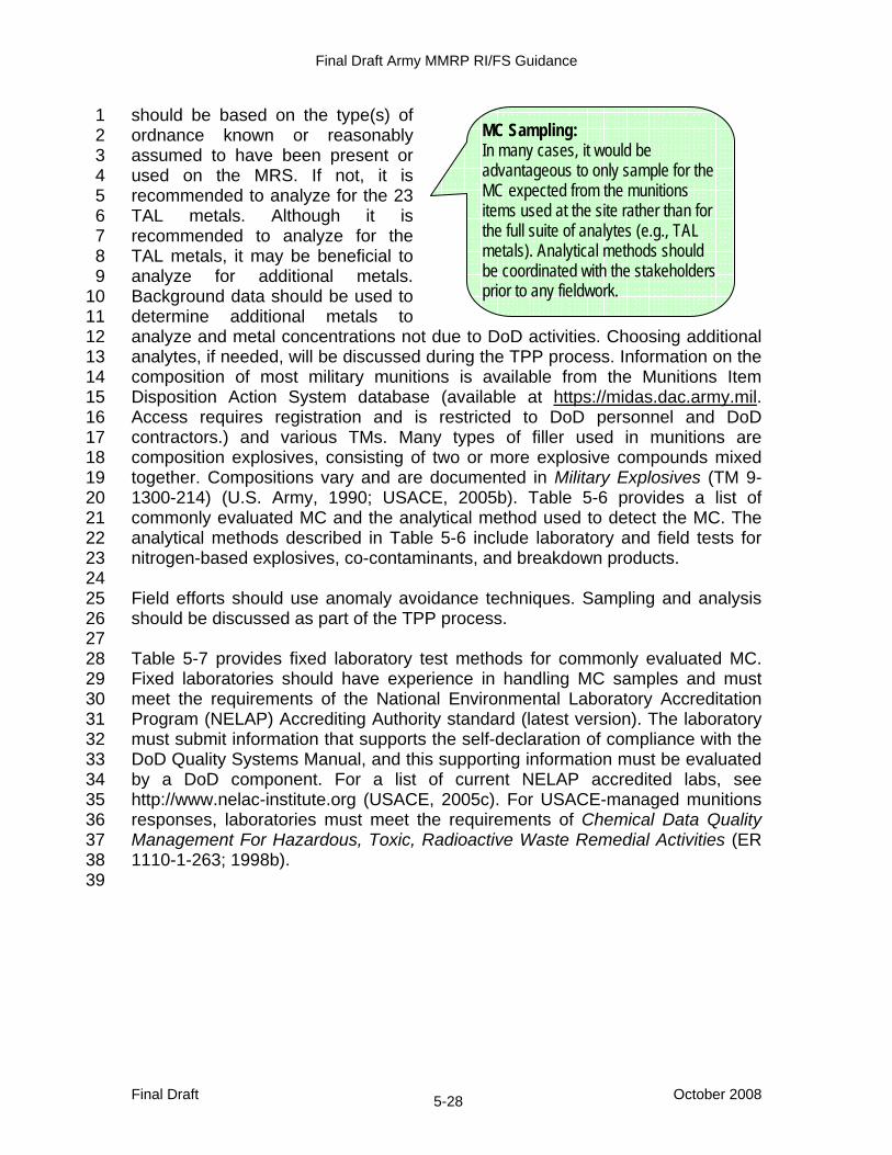
Final Draft Army MMRP RI/FS Guidance
Final Draft October 2008 5-28
should be based on the type(s) of 1 ordnance known or reasonably 2 assumed to have been present or 3 used on the MRS. If not, it is 4 recommended to analyze for the 23 5 TAL metals. Although it is 6 recommended to analyze for the 7 TAL metals, it may be beneficial to 8 analyze for additional metals. 9 Background data should be used to 10 determine additional metals to 11 analyze and metal concentrations not due to DoD activities. Choosing additional 12 analytes, if needed, will be discussed during the TPP process. Information on the 13 composition of most military munitions is available from the Munitions Item 14 Disposition Action System database (available at https://midas.dac.army.mil. 15 Access requires registration and is restricted to DoD personnel and DoD 16 contractors.) and various TMs. Many types of filler used in munitions are 17 composition explosives, consisting of two or more explosive compounds mixed 18 together. Compositions vary and are documented in Military Explosives (TM 9-19 1300-214) (U.S. Army, 1990; USACE, 2005b). Table 5-6 provides a list of 20 commonly evaluated MC and the analytical method used to detect the MC. The 21 analytical methods described in Table 5-6 include laboratory and field tests for 22 nitrogen-based explosives, co-contaminants, and breakdown products. 23 24 Field efforts should use anomaly avoidance techniques. Sampling and analysis 25 should be discussed as part of the TPP process. 26 27 Table 5-7 provides fixed laboratory test methods for commonly evaluated MC. 28 Fixed laboratories should have experience in handling MC samples and must 29 meet the requirements of the National Environmental Laboratory Accreditation 30 Program (NELAP) Accrediting Authority standard (latest version). The laboratory 31 must submit information that supports the self-declaration of compliance with the 32 DoD Quality Systems Manual, and this supporting information must be evaluated 33 by a DoD component. For a list of current NELAP accredited labs, see 34 http://www.nelac-institute.org (USACE, 2005c). For USACE-managed munitions 35 responses, laboratories must meet the requirements of Chemical Data Quality 36 Management For Hazardous, Toxic, Radioactive Waste Remedial Activities (ER 37 1110-1-263; 1998b). 38 39
MC Sampling: In many cases, it would be advantageous to only sample for the MC expected from the munitions items used at the site rather than for the full suite of analytes (e.g., TAL metals). Analytical methods should be coordinated with the stakeholders prior to any fieldwork.
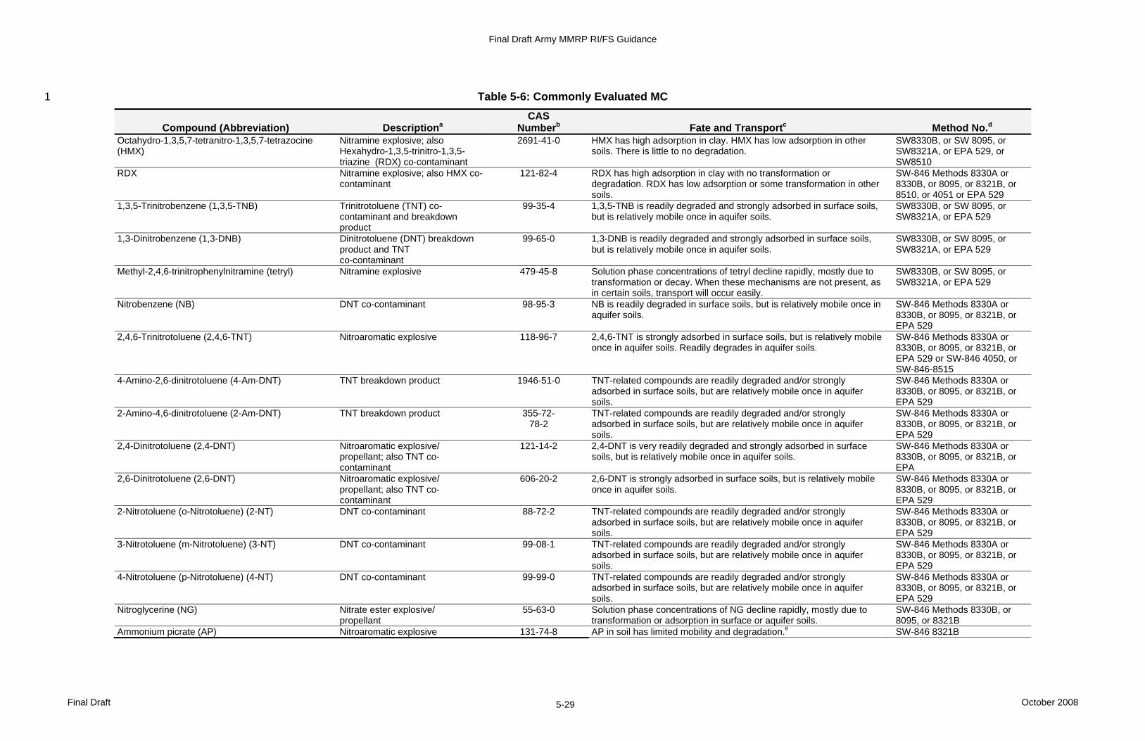
Final Draft Army MMRP RI/FS Guidance
Final Draft October 2008 5-29
Table 5-6: Commonly Evaluated MC 1
Compound (Abbreviation) Descriptiona CAS
Numberb Fate and Transportc Method No.d Octahydro-1,3,5,7-tetranitro-1,3,5,7-tetrazocine (HMX)
Nitramine explosive; also Hexahydro-1,3,5-trinitro-1,3,5-triazine (RDX) co-contaminant
2691-41-0 HMX has high adsorption in clay. HMX has low adsorption in other soils. There is little to no degradation.
SW8330B, or SW 8095, or SW8321A, or EPA 529, or SW8510
RDX Nitramine explosive; also HMX co-contaminant
121-82-4 RDX has high adsorption in clay with no transformation or degradation. RDX has low adsorption or some transformation in other soils.
SW-846 Methods 8330A or 8330B, or 8095, or 8321B, or 8510, or 4051 or EPA 529
1,3,5-Trinitrobenzene (1,3,5-TNB) Trinitrotoluene (TNT) co-contaminant and breakdown product
99-35-4 1,3,5-TNB is readily degraded and strongly adsorbed in surface soils, but is relatively mobile once in aquifer soils.
SW8330B, or SW 8095, or SW8321A, or EPA 529
1,3-Dinitrobenzene (1,3-DNB) Dinitrotoluene (DNT) breakdown product and TNT co-contaminant
99-65-0 1,3-DNB is readily degraded and strongly adsorbed in surface soils, but is relatively mobile once in aquifer soils.
SW8330B, or SW 8095, or SW8321A, or EPA 529
Methyl-2,4,6-trinitrophenylnitramine (tetryl) Nitramine explosive 479-45-8 Solution phase concentrations of tetryl decline rapidly, mostly due to transformation or decay. When these mechanisms are not present, as in certain soils, transport will occur easily.
SW8330B, or SW 8095, or SW8321A, or EPA 529
Nitrobenzene (NB) DNT co-contaminant 98-95-3 NB is readily degraded in surface soils, but is relatively mobile once in aquifer soils.
SW-846 Methods 8330A or 8330B, or 8095, or 8321B, or EPA 529
2,4,6-Trinitrotoluene (2,4,6-TNT) Nitroaromatic explosive 118-96-7 2,4,6-TNT is strongly adsorbed in surface soils, but is relatively mobile once in aquifer soils. Readily degrades in aquifer soils.
SW-846 Methods 8330A or 8330B, or 8095, or 8321B, or EPA 529 or SW-846 4050, or SW-846-8515
4-Amino-2,6-dinitrotoluene (4-Am-DNT) TNT breakdown product 1946-51-0 TNT-related compounds are readily degraded and/or strongly adsorbed in surface soils, but are relatively mobile once in aquifer soils.
SW-846 Methods 8330A or 8330B, or 8095, or 8321B, or EPA 529
2-Amino-4,6-dinitrotoluene (2-Am-DNT) TNT breakdown product 355-72- 78-2
TNT-related compounds are readily degraded and/or strongly adsorbed in surface soils, but are relatively mobile once in aquifer soils.
SW-846 Methods 8330A or 8330B, or 8095, or 8321B, or EPA 529
2,4-Dinitrotoluene (2,4-DNT) Nitroaromatic explosive/ propellant; also TNT co-contaminant
121-14-2 2,4-DNT is very readily degraded and strongly adsorbed in surface soils, but is relatively mobile once in aquifer soils.
SW-846 Methods 8330A or 8330B, or 8095, or 8321B, or EPA
2,6-Dinitrotoluene (2,6-DNT) Nitroaromatic explosive/ propellant; also TNT co-contaminant
606-20-2 2,6-DNT is strongly adsorbed in surface soils, but is relatively mobile once in aquifer soils.
SW-846 Methods 8330A or 8330B, or 8095, or 8321B, or EPA 529
2-Nitrotoluene (o-Nitrotoluene) (2-NT) DNT co-contaminant 88-72-2 TNT-related compounds are readily degraded and/or strongly adsorbed in surface soils, but are relatively mobile once in aquifer soils.
SW-846 Methods 8330A or 8330B, or 8095, or 8321B, or EPA 529
3-Nitrotoluene (m-Nitrotoluene) (3-NT) DNT co-contaminant 99-08-1 TNT-related compounds are readily degraded and/or strongly adsorbed in surface soils, but are relatively mobile once in aquifer soils.
SW-846 Methods 8330A or 8330B, or 8095, or 8321B, or EPA 529
4-Nitrotoluene (p-Nitrotoluene) (4-NT) DNT co-contaminant 99-99-0 TNT-related compounds are readily degraded and/or strongly adsorbed in surface soils, but are relatively mobile once in aquifer soils.
SW-846 Methods 8330A or 8330B, or 8095, or 8321B, or EPA 529
Nitroglycerine (NG) Nitrate ester explosive/ propellant
55-63-0 Solution phase concentrations of NG decline rapidly, mostly due to transformation or adsorption in surface or aquifer soils.
SW-846 Methods 8330B, or 8095, or 8321B
Ammonium picrate (AP) Nitroaromatic explosive 131-74-8 AP in soil has limited mobility and degradation.e SW-846 8321B
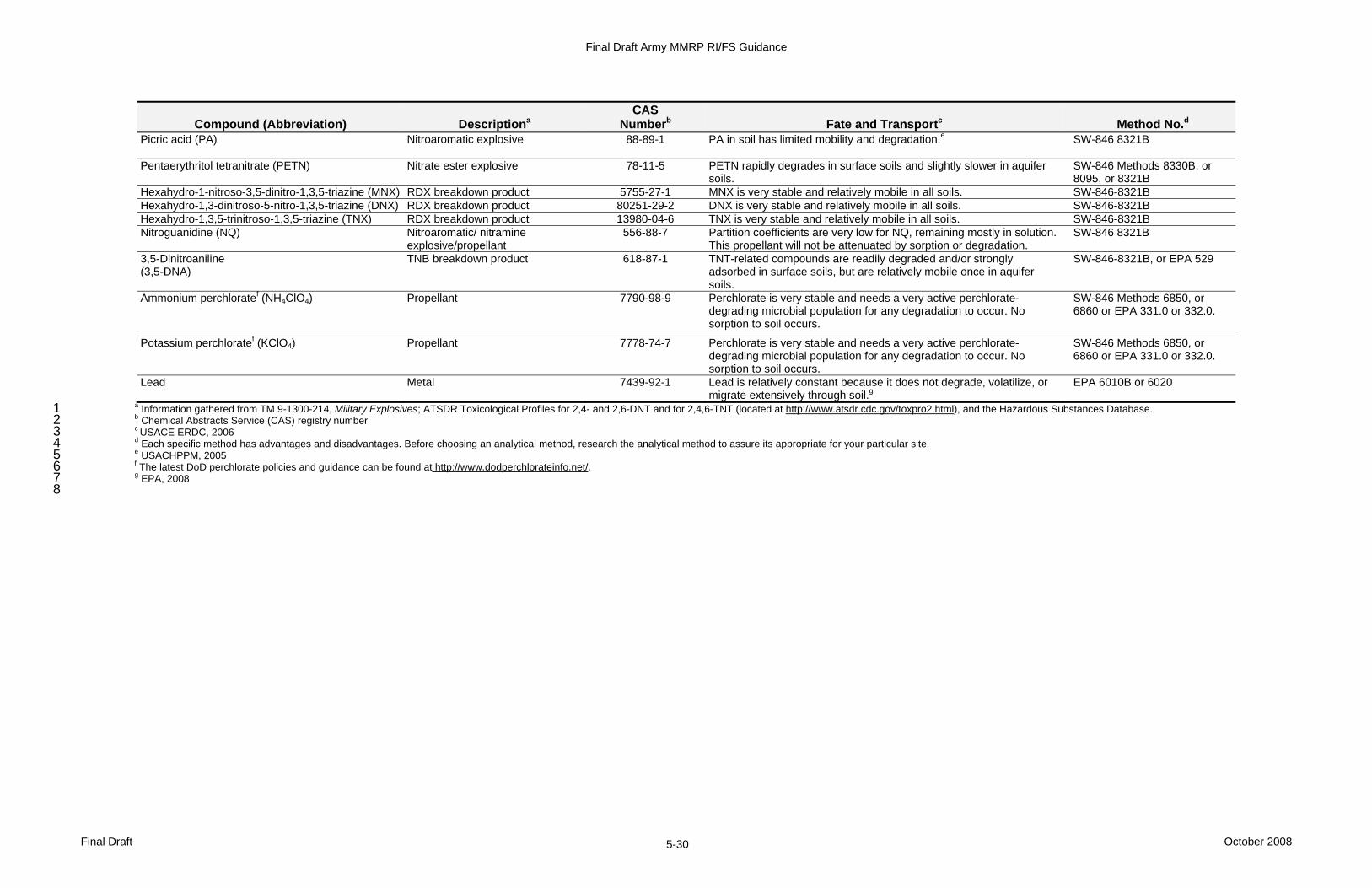
Final Draft Army MMRP RI/FS Guidance
Final Draft October 2008 5-30
Compound (Abbreviation) Descriptiona CAS
Numberb Fate and Transportc Method No.d Picric acid (PA)
Nitroaromatic explosive 88-89-1 PA in soil has limited mobility and degradation.e SW-846 8321B
Pentaerythritol tetranitrate (PETN) Nitrate ester explosive 78-11-5 PETN rapidly degrades in surface soils and slightly slower in aquifer soils.
SW-846 Methods 8330B, or 8095, or 8321B
Hexahydro-1-nitroso-3,5-dinitro-1,3,5-triazine (MNX) RDX breakdown product 5755-27-1 MNX is very stable and relatively mobile in all soils. SW-846-8321B Hexahydro-1,3-dinitroso-5-nitro-1,3,5-triazine (DNX) RDX breakdown product 80251-29-2 DNX is very stable and relatively mobile in all soils. SW-846-8321B Hexahydro-1,3,5-trinitroso-1,3,5-triazine (TNX) RDX breakdown product 13980-04-6 TNX is very stable and relatively mobile in all soils. SW-846-8321B Nitroguanidine (NQ) Nitroaromatic/ nitramine
explosive/propellant 556-88-7 Partition coefficients are very low for NQ, remaining mostly in solution.
This propellant will not be attenuated by sorption or degradation. SW-846 8321B
3,5-Dinitroaniline (3,5-DNA)
TNB breakdown product 618-87-1 TNT-related compounds are readily degraded and/or strongly adsorbed in surface soils, but are relatively mobile once in aquifer soils.
SW-846-8321B, or EPA 529
Ammonium perchloratef (NH4ClO4) Propellant 7790-98-9 Perchlorate is very stable and needs a very active perchlorate-degrading microbial population for any degradation to occur. No sorption to soil occurs.
SW-846 Methods 6850, or 6860 or EPA 331.0 or 332.0.
Potassium perchloratef (KClO4) Propellant 7778-74-7 Perchlorate is very stable and needs a very active perchlorate-degrading microbial population for any degradation to occur. No sorption to soil occurs.
SW-846 Methods 6850, or 6860 or EPA 331.0 or 332.0.
Lead Metal 7439-92-1 Lead is relatively constant because it does not degrade, volatilize, or migrate extensively through soil.g
EPA 6010B or 6020
a Information gathered from TM 9-1300-214, Military Explosives; ATSDR Toxicological Profiles for 2,4- and 2,6-DNT and for 2,4,6-TNT (located at http://www.atsdr.cdc.gov/toxpro2.html), and the Hazardous Substances Database. 1 b Chemical Abstracts Service (CAS) registry number 2 c USACE ERDC, 2006 3 d Each specific method has advantages and disadvantages. Before choosing an analytical method, research the analytical method to assure its appropriate for your particular site. 4 e USACHPPM, 2005 5 f The latest DoD perchlorate policies and guidance can be found at http://www.dodperchlorateinfo.net/. 6 g EPA, 2008 7
8
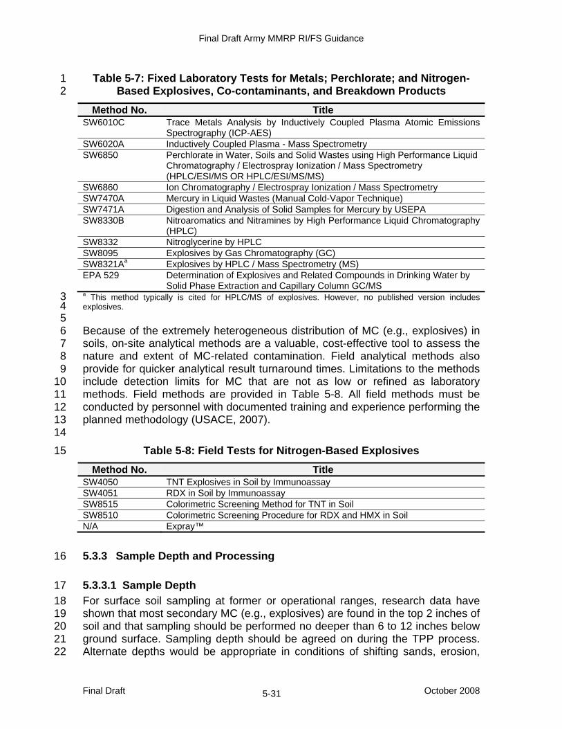
Final Draft Army MMRP RI/FS Guidance
Final Draft October 2008 5-31
Table 5-7: Fixed Laboratory Tests for Metals; Perchlorate; and Nitrogen-1 Based Explosives, Co-contaminants, and Breakdown Products 2
Method No. Title SW6010C Trace Metals Analysis by Inductively Coupled Plasma Atomic Emissions
Spectrography (ICP-AES) SW6020A Inductively Coupled Plasma - Mass Spectrometry SW6850 Perchlorate in Water, Soils and Solid Wastes using High Performance Liquid
Chromatography / Electrospray Ionization / Mass Spectrometry (HPLC/ESI/MS OR HPLC/ESI/MS/MS)
SW6860 Ion Chromatography / Electrospray Ionization / Mass Spectrometry SW7470A Mercury in Liquid Wastes (Manual Cold-Vapor Technique) SW7471A Digestion and Analysis of Solid Samples for Mercury by USEPA SW8330B Nitroaromatics and Nitramines by High Performance Liquid Chromatography
(HPLC) SW8332 Nitroglycerine by HPLC SW8095 Explosives by Gas Chromatography (GC) SW8321Aa Explosives by HPLC / Mass Spectrometry (MS) EPA 529 Determination of Explosives and Related Compounds in Drinking Water by
Solid Phase Extraction and Capillary Column GC/MS a This method typically is cited for HPLC/MS of explosives. However, no published version includes 3 explosives. 4 5 Because of the extremely heterogeneous distribution of MC (e.g., explosives) in 6 soils, on-site analytical methods are a valuable, cost-effective tool to assess the 7 nature and extent of MC-related contamination. Field analytical methods also 8 provide for quicker analytical result turnaround times. Limitations to the methods 9 include detection limits for MC that are not as low or refined as laboratory 10 methods. Field methods are provided in Table 5-8. All field methods must be 11 conducted by personnel with documented training and experience performing the 12 planned methodology (USACE, 2007). 13 14
Table 5-8: Field Tests for Nitrogen-Based Explosives 15
Method No. Title SW4050 TNT Explosives in Soil by Immunoassay SW4051 RDX in Soil by Immunoassay SW8515 Colorimetric Screening Method for TNT in Soil SW8510 Colorimetric Screening Procedure for RDX and HMX in Soil N/A Expray™
5.3.3 Sample Depth and Processing 16
5.3.3.1 Sample Depth 17 For surface soil sampling at former or operational ranges, research data have 18 shown that most secondary MC (e.g., explosives) are found in the top 2 inches of 19 soil and that sampling should be performed no deeper than 6 to 12 inches below 20 ground surface. Sampling depth should be agreed on during the TPP process. 21 Alternate depths would be appropriate in conditions of shifting sands, erosion, 22
Final Draft Army MMRP RI/FS Guidance
Final Draft October 2008 5-32
grading, etc. If MEC items are expected or found in the subsurface, initial 1 sampling should also be taken from subsurface soil near the identified MEC or 2 munitions debris location. Subsurface MEC avoidance techniques need to be 3 followed (USACE, 2007). 4 5 If significant releases of MC are believed to have occurred, groundwater 6 sampling should be considered. The decision to sample groundwater should be 7 made based on depth to groundwater, its susceptibility from surface releases, 8 potential receptors, the magnitude of the suspected MC release, and the type of 9 MC suspected at the site. If surface water is located on or near the MRS and 10 receives runoff from suspected MC source areas, surface water / sediment 11 sampling should be considered. 12
5.3.3.2 Sampling Schemes 13 For MC sampling during the RI/FS, the available methods for sample collection 14 include discrete sampling, composite sampling (spoke and hub), and multi-15 incremental sampling. These collection methods have been used and 16 documented during CRREL’s R&D efforts. The types of sample collection to be 17 used are decided by the MR Project Team during the TPP process. 18 19 Discrete soil samples provide point concentrations. However, because of the 20 distribution of explosives on live-fire ranges, discrete samples are not 21 reproducible and can give concentrations of an order of magnitude difference in 22 adjacent samples. Discrete samples may be appropriate for low-order 23 detonations or under a munition (e.g., UXO or DMM) following its removal or 24 detonation in place as decided by stakeholders during the TPP process. 25 26 Composite sampling was developed by CRREL as a way to show the differences 27 in discrete sampling compared to composite sampling. A spoke and hub template 28 of seven samples was used. The findings from this sampling technique led to the 29 development of the multi-increment (MI) sampling approach. This seven spoke 30 sampling template will not be used for MC sampling, as the MI sampling 31 approach will produce significantly more representative data. 32 33 MI sampling involves the collection of 30 or more individual samples over a 34 defined decision unit. The result of MI sampling has been shown to provide a 35 reproducible decision unit average concentration. The recent update of 36 SW8330B (http://www.epa.gov/epaoswer/hazwaste/ test/new-meth.htm) includes 37 specific guidance on multi-incremental sampling. 38 39 SW8330B recommends collecting 1000 grams (g) of soil and sieving and 40 grinding the entire sample prior to subsampling. The sieving and grinding may 41 occur in the field or in the laboratory. For additional information on laboratory 42 subsampling, see Guidance for Obtaining Representative Laboratory Analytical 43 Subsamples from Particulate Laboratory Samples (EPA, 2003a at http://www.clu-44 in.org/download/char/epa_subsampling_guidance.pdf). 45
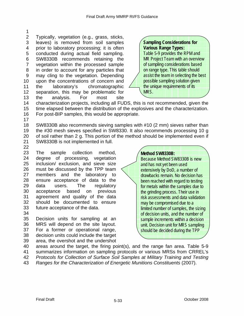
Final Draft Army MMRP RI/FS Guidance
Final Draft October 2008 5-33
1 Typically, vegetation (e.g., grass, sticks, 2 leaves) is removed from soil samples 3 prior to laboratory processing; it is often 4 conducted during actual field sampling. 5 SW8330B recommends retaining the 6 vegetation within the processed sample 7 in order to account for any particles that 8 may cling to the vegetation. Depending 9 upon the concentrations of concern and 10 the laboratory’s chromatographic 11 separation, this may be problematic for 12 the analysis. For most site 13 characterization projects, including all FUDS, this is not recommended, given the 14 time elapsed between the distribution of the explosives and the characterization. 15 For post-BIP samples, this would be appropriate. 16 17 SW8330B also recommends sieving samples with #10 (2 mm) sieves rather than 18 the #30 mesh sieves specified in SW8330. It also recommends processing 10 g 19 of soil rather than 2 g. This portion of the method should be implemented even if 20 SW8330B is not implemented in full. 21 22 The sample collection method, 23 degree of processing, vegetation 24 inclusion/ exclusion, and sieve size 25 must be discussed by the TPP team 26 members and the laboratory to 27 ensure acceptance of data to the 28 data users. The regulatory 29 acceptance based on previous 30 agreement and quality of the data 31 should be documented to ensure 32 future acceptance of the data. 33 34 Decision units for sampling at an 35 MRS will depend on the site layout. 36 For a former or operational range, 37 decision units could include the target 38 area, the overshot and the undershot 39 areas around the target, the firing point(s), and the range fan area. Table 5-9 40 summarizes information on sampling protocols or various MRSs from CRREL’s 41 Protocols for Collection of Surface Soil Samples at Military Training and Testing 42 Ranges for the Characterization of Energetic Munitions Constituents (2007). 43
Sampling Considerations for Various Range Types: Table 5-9 provides the RPM and MR Project Team with an overview of sampling considerations based on range type. This table should assist the team in selecting the best possible sampling solution given the unique requirements of its MRS.
Method SW8330B: Because Method SW8330B is new and has not yet been used extensively by DoD, a number of drawbacks remain. No decision has been reached with regard to testing for metals within the samples due to the grinding process. Their use in risk assessments and data validation may be compromised due to a limited number of samples, the sizing of decision units, and the number of sample increments within a decision unit. Decision unit for MRS sampling should be decided during the TPP
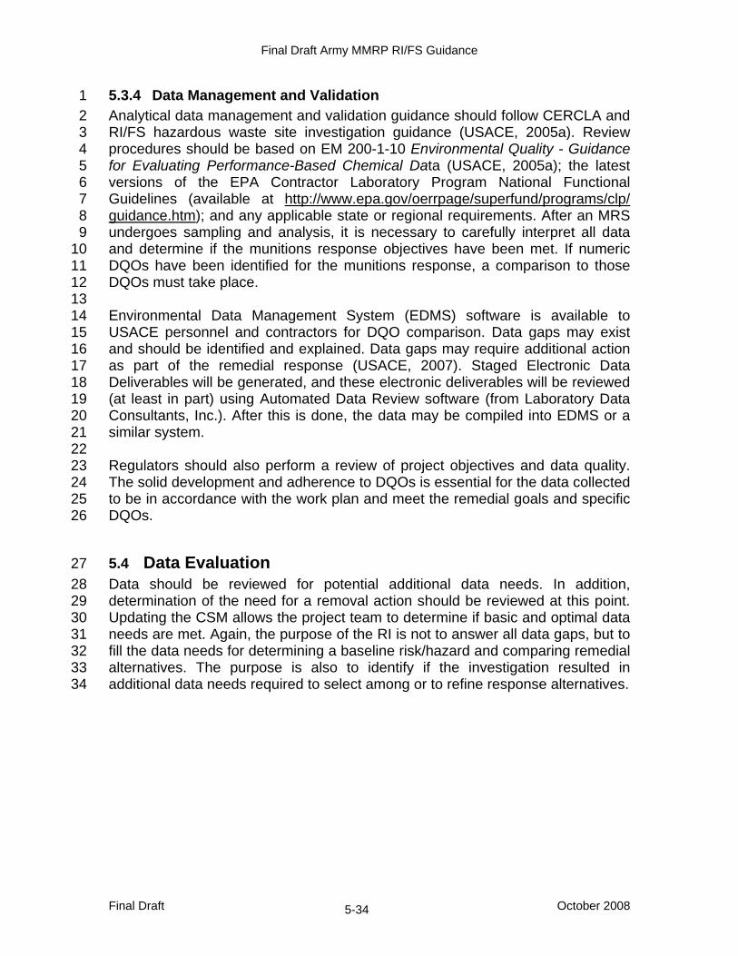
Final Draft Army MMRP RI/FS Guidance
Final Draft October 2008 5-34
5.3.4 Data Management and Validation 1 Analytical data management and validation guidance should follow CERCLA and 2 RI/FS hazardous waste site investigation guidance (USACE, 2005a). Review 3 procedures should be based on EM 200-1-10 Environmental Quality - Guidance 4 for Evaluating Performance-Based Chemical Data (USACE, 2005a); the latest 5 versions of the EPA Contractor Laboratory Program National Functional 6 Guidelines (available at http://www.epa.gov/oerrpage/superfund/programs/clp/ 7 guidance.htm); and any applicable state or regional requirements. After an MRS 8 undergoes sampling and analysis, it is necessary to carefully interpret all data 9 and determine if the munitions response objectives have been met. If numeric 10 DQOs have been identified for the munitions response, a comparison to those 11 DQOs must take place. 12 13 Environmental Data Management System (EDMS) software is available to 14 USACE personnel and contractors for DQO comparison. Data gaps may exist 15 and should be identified and explained. Data gaps may require additional action 16 as part of the remedial response (USACE, 2007). Staged Electronic Data 17 Deliverables will be generated, and these electronic deliverables will be reviewed 18 (at least in part) using Automated Data Review software (from Laboratory Data 19 Consultants, Inc.). After this is done, the data may be compiled into EDMS or a 20 similar system. 21 22 Regulators should also perform a review of project objectives and data quality. 23 The solid development and adherence to DQOs is essential for the data collected 24 to be in accordance with the work plan and meet the remedial goals and specific 25 DQOs. 26
5.4 Data Evaluation 27 Data should be reviewed for potential additional data needs. In addition, 28 determination of the need for a removal action should be reviewed at this point. 29 Updating the CSM allows the project team to determine if basic and optimal data 30 needs are met. Again, the purpose of the RI is not to answer all data gaps, but to 31 fill the data needs for determining a baseline risk/hazard and comparing remedial 32 alternatives. The purpose is also to identify if the investigation resulted in 33 additional data needs required to select among or to refine response alternatives. 34

Final Draft Army MMRP RI/FS Guidance
Final Draft October 2008 5-35
Table 5-9: MI Sampling Considerations for Various Range Types Range Type Description
Typical Weapons Used Typical MC Sampling Designa Additional Considerations
Hand grenade range
Hand grenade ranges are small throwing bays, sometimes divided into several courts. Practice is to throw grenade from behind a fortified earthen wall into an impact area.
• M67 fragmentation grenade
• Composition B (RDX, TNT) • MC should include degradation products
and impurities of RDX and TNT.
• MI samples will target the area between the front bay to the impact area, all along the impact area’s width. Sample depth is dependent on the depth of penetration for a hand grenade; the sample depth should reflect this depth of penetration. For areas < 100 square meters (m2), recommend 30 increments to prepare MI sample along a systematic grid. For areas > 100 m2, recommend 30–100 increments, depending on site size. Number of samples will be agreed to during the TPP process. Depth profiles are recommended as a single five-increment sample.
• When courts are not separated by barriers, sample as single decision unit.
• Deposition is normally at surface; however, with cratering and range management, this will vary.
Anti-tank rocket range
Rocket projectiles are fired from shoulder-mounted tubes.
• 66 mm M72 Light Anti-armor Weapon (LAW)
• AT4 rockets
• Practice rounds include propellant, but no high explosive warhead.
• LAW rocket warheads include Octol (HMX, TNT) with a tetryl or RDX booster, M7 double-base (nitrocellulose [NC]/NG) propellant, potassium perchlorate, and carbon black.
• For the target area, MI sample should be taken in areas where most munitions residues are expected to be found (near targets, etc). Increments should be determined based on the size of the decision unit, as indicated above. A segmented halo design can establish MI samples within the individual segment areas.
• For the firing point, determine where subsurface accumulation of energetic residue is likely to occur and collect the MI sample at the depth of penetration.
• Explosive and propellant residues are present in front of and behind the firing line and around targets.
Artillery range
Artillery ranges are the largest Army training ranges.
• 155 mm howitzer • 105 mm artillery
projectiles • 120 mm tank
projectiles • 81 mm, 60 mm, and
120 mm mortar rounds
• Various smaller munitions
• High explosive components include TNT, Composition B, tetryl, octyl, etc.
• Single-based (NC; 2,4-DNT), double-based (NC/NG), and triple-based (NC/NG/NQ) gun propellants were used.
• For impact areas, use a square grid centered on each target, with an MI sample from top using a systematic grid pattern.
• Point source samples may be taken near low-order detonations. Recommend a small grid centered around low-order detonations taking MI sample from top portion of soil.
• Depth profile samples of these areas are taken as a single increment MI sample at several separate depths to establish the depth at which residues have mixed into the soil profile.
• Other areas outside may be chosen for sampling and should follow the impact area grid, collecting MI sample from top.
• Low-order detonations of rockets/mortars pose the greatest risk for contaminant point sources in impact and target areas.
• Propellant residues at firing points are often found downrange where excess propellant was burned.
Bombing range
Various Various • Apply same principles for artillery impact ranges.
Demolition range
Various Various • Apply a grid within the OB area, collecting an MI sample from the top.
Small arms range
Various Various • Apply similar principles for hand grenade range. Soil samples should not include intact or fragmented bullets and lead shot. When samples are ground and analyzed, these can falsely indicate high bioavailability of lead in soil.
Source: USACE ERDC, 2007
Note: This is not a comprehensive table for MRSs, as there may be other types of sites and munitions that may need to be considered. a Detailed information is not included in this table. For detailed information regarding MI sampling, refer to USACE ERDC, 2007.

Final Draft Army MMRP RI/FS Guidance
Final Draft October 2008 5-36
This page intentionally left blank.
Final Draft Army MMRP RI/FS Guidance
Final Draft October 2008 5-37
5.5 Baseline Risk/Hazard Assessment 1 The National Academy of Sciences (NAS) defines risk as the potential for 2 adverse effects to an exposed population (NAS, 1983). It is a function of the 3 probability of an accident (or adverse situation) occurring within a certain period 4 of time and resulting in consequences to people, property, or the environment. 5 The intent of these documents is discussed in Sections 5.5.1 through 5.5.3. The 6 following definition of risk from the Presidential/Congressional Commission on 7 Risk Assessment and Risk Management (1997) gives a clearer understanding of 8 risk as it relates to the MMRP: 9
Risk is the probability that a substance or situation will produce 10 harm under specified conditions and is a combination of two 11 factors: (1) the probability that an adverse event will occur and (2) 12 the consequences of an adverse event. 13 14
The EPA has developed general risk assessment methods for evaluating human 15 health and environmental risks at hazardous and toxic waste sites that follow the 16 basic relationship established by the NAS. These general risk assessment 17 methods are conducted through four basic steps: (1) hazard identification, (2) 18 exposure assessment, (3) dose response modeling, and (4) risk characterization 19 (NAS, 1983; EPA, 1988). These methods typically are used to quantify risk from 20 long-term, chronic exposure to varying levels of chemical contamination. 21 22 As the potential threats by MEC and MC are different, they have come to be 23 separated by the terms “hazard” and “risk.” A risk/hazard assessment evaluates 24 the risk of injury or death from any explosive hazard present. An MC risk 25 assessment evaluates the potential threat of carcinogenic risk or 26 noncarcinogenic hazard to human health and the environment through exposure 27 to MC. The MRSPP is used to determine the relative risk posed by UXO, DMM, 28 or MC at an MRS. 29 30 Explosive hazards may exist when MEC are known or suspected to be present at 31 an MRS. The exposure to MEC can occur if a receptor has access to an MRS, 32 MEC are present on the surface or may be exposed from the subsurface as a 33 result of the activity to be conducted, and the receptor makes physical contact 34 with any MEC encountered. An encounter with MEC may have one of three 35 outcomes: no effect, injury, or death. The established method for characterizing 36 the relative risk associated with the presence of UXO, DMM, or MC is application 37 of the MRSPP. The EPA, working with the DoD and the states, has also 38 developed a risk/hazard assessment tool for evaluating the relative risks that 39 may remain after implementation of alternative munitions response actions. 40 41 This risk/hazard assessment tool describes and estimates the likelihood of 42 adverse outcomes from an encounter with MEC. Several methods have been 43 developed for performing a risk/hazard assessment on an MRS; however, no 44

Final Draft Army MMRP RI/FS Guidance
Final Draft October 2008 5-38
single methodology has been widely accepted, tested, and fully implemented. 1 Both quantitative and qualitative methods evaluate MEC hazards. Information on 2 available risk tools is on the USACE Ordnance and Explosives Directorate Web 3 site (http://www.hnd.usace.army.mil/oew/index.aspx). 4 5 Without a quantitative risk assessment model, the exit criteria for a munitions 6 response at an MRS must be determined on a site-by-site basis in collaboration 7 with environmental regulators and Army explosive safety officials and consistent 8 with future land use. The risk/hazard 9 assessment and other qualitative methods 10 are tools for qualitatively describing the 11 explosive hazard and are not meant to be 12 the decision makers. 13 14 If the risk/hazard assessment tool is not 15 available to the MR Project Team during 16 implementation of the RI and the MR 17 Project Team does not accept other 18 methods, a qualitative discussion of the 19 hazard at the MRS should be developed by 20 the MR Project Team. If the risk/hazard 21 assessment tool is available to the MR 22 Project Team, it should be augmented with a qualitative discussion of risk in 23 relation to current and reasonably anticipated future users of the property. 24
5.5.1 U.S. Environmental Protection Agency Munitions and Explosives of 25 Concern Hazard Assessment 26
A multiagency (EPA, OSD, Army, Navy, states, Department of Interior, and 27 tribes) workgroup has developed risk/hazard assessment (2008) to promote 28 mutual understanding of technical issues of an MRS through a collaborative, 29 team-based HA process. The method is currently in public review form. The EPA 30 risk/hazard assessment is designed to enhance communication of hazards within 31 an MR Project Team and between project teams and external stakeholders. Use 32 of the risk/hazard assessment should facilitate evaluation of removal and 33 remedial alternatives and evaluation of determined or reasonably anticipated 34 future land use activities. 35 36 The EPA risk/hazard assessment reflects the fundamental difference between 37 assessing chronic chemical exposure risk and assessing acute MEC explosive 38 hazards. An explosive hazard can result in immediate injury or death. Risks from 39 UXO explosive hazards are evaluated as being either present or not present. If 40 the potential for an encounter with MEC exists, the potential that the encounter 41 could result in death or injury also exists. According to the risk/hazard 42 assessment, if MEC are known or suspected to be present, a munitions response 43 (e.g., investigation) will normally be a removal or remedial action. As a general 44
Exit Criteria for MRA/MRS: The RPM and MR Project Team should develop an exit strategy for an MRA/MRS in conjunction with the stakeholders. This task is complicated by the lack of an accepted risk assessment model. A key element of the exit strategy for the subject MRA/MRS is the accepted future land use!
Final Draft Army MMRP RI/FS Guidance
Final Draft October 2008 5-39
rule, munitions responses (i.e., removal or remedial) will include implementation 1 of LUCs. In some cases, LUCs alone may suffice. 2 3 The EPA risk/hazard assessment addresses human health and safety concerns 4 associated with potential exposure to MEC at land-based sites. It does not 5 address underwater sites, nor does it address the chemical agent hazards 6 associated with CWM sites, nor does it directly address environmental or 7 ecological concerns that might be associated with MEC. 8
5.5.2 U.S. Army Corps of Engineers Ordnance and Explosives Risk Impact 9 Assessment 10
The OERIA provides a qualitative risk assessment tool that aids in risk 11 communication. The OERIA provides a table to compile information and rank an 12 MRS using the following factors: munitions type, sensitivity, estimated density 13 and depth, site accessibility and stability, human activities, and population. A 14 baseline score is developed based on best professional judgment. Actions (e.g., 15 ICs, clearance to a detectable depth) are evaluated, and relative scores are 16 given for each of the resulting site conditions. The table acts as a tool to compare 17 the results of response action alternatives and relies heavily on the MR Project 18 Team to analyze the results and select an alternative. The baseline risk 19 assessment is used to assess the relative impact that response alternatives may 20 have on reducing unacceptable risk of MC. The output of the method is a table 21 with each response alternative ranked with a letter grade (A being the highest) 22 for all risk factors identified. The MR Project Team should refer to USAESCH’s 23 2001 Interim Guidance Ordnance and Explosives Risk Impact Assessment for 24 further information on using the OERIA. 25
5.5.3 Munitions Constituents Risk Assessment 26 Risks posed by MC are assessed through a baseline risk assessment that 27 adheres to the requirements of CERCLA and the NCP. The following documents 28 provide the guidance for conducting risk assessments: 29
• EM 200-1-4 Environmental Quality - Risk Assessment Handbook - 30 Volume I: Human Health Evaluation and Volume 2: Environmental 31 Evaluation (USACE, 1999a and 1996) 32
• EM 1110-1-4009 Military Munitions Response Actions (USACE, 2007) 33 • EPA 540/1-89/002 Risk Assessment Guidance for Superfund (RAGS), 34
Volume I, Human Health Evaluation Manual (Part A), Interim Final 35 (1989b) 36
• EPA 540/G-89/004 Guidance for Conducting Remedial Investigations 37 and Feasibility Studies Under CERCLA, Interim Final (1988) 38
• EPA 540-R-97-006 Ecological Risk Assessment Guidance for 39 Superfund, Process for Designing and Conducting Ecological Risk 40 Assessments (1997) 41

Final Draft Army MMRP RI/FS Guidance
Final Draft October 2008 5-40
1 State risk assessment protocols should also be considered, keeping in mind that 2 MR Project Team approval is required prior to following any state-specific 3 cleanup plan. 4
5.6 Assessment of Required Interim Measures 5 In general, the Army expects the remedial process to be the most effective 6 solution for the majority of MRSs. If, 7 during the course of an RI/FS, site 8 characterization indicates the need for a 9 more immediate removal action, the MR 10 Project Team can and should switch 11 actions. However, following the removal 12 action, the munitions response should 13 transition back to the RI/FS process. 14 Therefore, it is preferable to limit 15 removal actions and perform interim 16 remedial actions that are determined 17 based on the overall remedial action 18 instead of performing removal actions 19 that require additional documentation 20 and assessment. 21 22 If either before the RI/FS begins or during the course of the investigation an 23 immediate threat is found, a removal action or interim remedial action may be 24 required. Removal actions are an integral part of the overall CERCLA process for 25 the MMRP, and a munitions response can enter the removal action phase from 26 any point in the CERCLA process, if deemed necessary. Factors determining the 27 need for a removal include property conditions, potential receptors, migration 28 pathways, and risk/hazard assessments. Removal actions generally have limited 29 objectives and typically are short term to mitigate the threat posed by a release 30 or threatened release of UXO, DMM, or MC. 31
5.6.1 Remedial Actions and Removal Actions 32 The NCP §300.415 categorizes removal actions in three ways: emergency, time-33 critical, and non-time-critical based upon the situation, the urgency and threat of 34 release or potential release, and the subsequent timeframe in which the action 35 must be initiated. Each type of removal action is discussed in detail below. When 36 appropriate, removal actions can be conducted as part of a munitions response. 37 Such responses normally reduce risks and may reduce the total cost. Removals 38 are normally expedited response actions, as opposed to final remedial actions, 39 which are usually intended to provide permanent remedies. 40
• Emergency removal actions: Emergency removal actions address 41 immediate, unacceptable hazards or risks and must commence within 42
Removal Actions: When a removal action is conducted within or in conjunction with the remedial response, the removal action will, to the extent practicable, contribute to the efficient performance of any anticipated long-term remedial action. When the removal action is completed, the munitions response normally will transition back to the RI/FS process.
Final Draft Army MMRP RI/FS Guidance
Final Draft October 2008 5-41
hours of discovery. Due to the exigency of an emergency removal, an 1 Action Memorandum (AM) is not required prior to performing the 2 emergency removal. Emergency removal actions include EOD response 3 to an immediate identification of MEC. Emergency removal actions are 4 described in ER 200-3-1 (USACE, 2004c). 5
• TCRA: A TCRA is an expedited removal action for which less than 6 6 months of planning time is available before on-site activities must begin. 7 TCRAs may be initiated at any phase of the munitions response. An AM 8 is required prior to performing the TCRA. TCRAs may be conducted for 9 situations that involve UXO, DMM, or MC alone or in combination. While 10 time may be limited, the TPP process should still be followed. 11
• NTCRA: The general difference between a TCRA and an NTCRA is the 12 amount of planning time that exists before on-site activities must be 13 initiated. For an NTRCA, a planning period of at least 6 months exists 14 before on-site activities must be initiated, and it has been determined 15 that a removal action is appropriate. An EE/CA will be conducted. An 16 AM is required prior to performing the NTCRA. Additional guidance for 17 NTCRAs is available in EPA 540-R-93-057 (1993). While time may be 18 limited, the TPP process should still be followed. 19
20 In addition to TCRAs and NTCRAs, the RI/FS may recommend Interim or 21 Contingent Remedial Actions to accomplish a mission similar to NTCRAs. The 22 Interim Remedial Action is implemented as a partial CERCLA response process. 23 24 For a removal action, an EE/CA is typically conducted. Typically, removal actions 25 are initiated in response to situations to abate, prevent, minimize, stabilize, 26 mitigate, or eliminate circumstances that pose an immediate and serious threat to 27 human health or the environment (EPA, 1988). Removal actions at MRSs on 28 active Army installations are usually the result of what the NCP characterizes as 29 an imminent “threat of fire or explosion.” 30 31 Remedial and removal actions are not mutually exclusive. For example, an MRA 32 with very complex conditions involving several MRSs with multiple sources and 33 types of UXO, DMM, or MC is addressed through a munitions response under 34 the remedial process. These MRSs may also involve individual removal actions. 35 When a removal action is conducted within or in conjunction with the remedial 36 response, the removal action will, to the extent practicable, contribute to the 37 efficient performance of any anticipated long-term remedial action. Following any 38 removal action (emergency, time-critical, or non-time-critical), the effort 39 transitions to the previous point in the remedial process to determine what 40 additional remedial action, if any, may be necessary to achieve the response in 41 place or response complete milestones or closeout (USACE, 2002). 42
Final Draft Army MMRP RI/FS Guidance
Final Draft October 2008 5-42
5.7 Remedial Investigation Reporting 1 The RI portion of the RI/FS report should include the MRS background, a 2 description of the physical characteristics, a description of the data collection and 3 analysis, the updated CSM, the baseline risk/hazard assessment, and the 4 recommended remedial action objectives. Development of RI objectives is 5 discussed in Section 4.1. An example RI/FS report outline is included in 6 Appendix D. 7
5.7.1 Update Conceptual Site Model 8 The CSM is refined with information collected during the RI. Given the results of 9 the RI, the MRS may become an MRA containing more than one MRS with 10 similar characteristics and corresponding response alternatives. A CSM would be 11 required for each MRS. 12
5.7.2 Update Munitions Response Site Prioritization Protocol 13 The MRSPP requires the DoD in consultation with representatives of the states 14 and Indian tribes, to assign each MRS a relative priority for response actions. 15 The MRSPP evaluates the potential explosive, chemical agents, and 16 environmental hazards at an MRS. A full description of the MRSPP process is 17 described in 32 CFR Section 179. 18 19 The MRS's initial MRSPP score shall be developed during the SI phase. These 20 scores must be reviewed annually and must be revised whenever new data are 21 obtained, such as in the RI/FS. 22 23
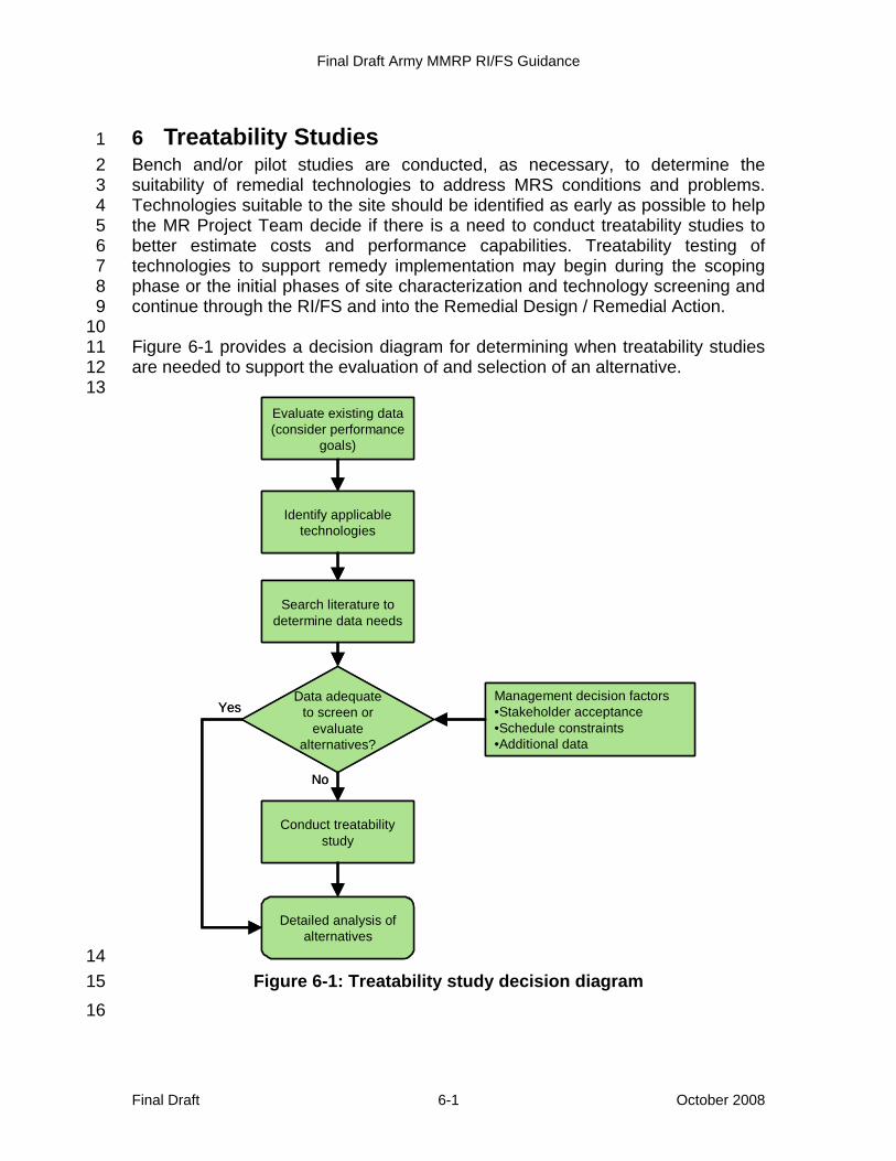
Final Draft Army MMRP RI/FS Guidance
Final Draft 6-1 October 2008
6 Treatability Studies 1 Bench and/or pilot studies are conducted, as necessary, to determine the 2 suitability of remedial technologies to address MRS conditions and problems. 3 Technologies suitable to the site should be identified as early as possible to help 4 the MR Project Team decide if there is a need to conduct treatability studies to 5 better estimate costs and performance capabilities. Treatability testing of 6 technologies to support remedy implementation may begin during the scoping 7 phase or the initial phases of site characterization and technology screening and 8 continue through the RI/FS and into the Remedial Design / Remedial Action. 9 10 Figure 6-1 provides a decision diagram for determining when treatability studies 11 are needed to support the evaluation of and selection of an alternative. 12 13
14 Figure 6-1: Treatability study decision diagram 15
16
Evaluate existing data (consider performance
goals)
Data adequate to screen or
evaluate alternatives?
Management decision factors•Stakeholder acceptance•Schedule constraints•Additional data
Yes
No
Identify applicable technologies
Search literature to determine data needs
Conduct treatabilitystudy
Detailed analysis of alternatives
Final Draft Army MMRP RI/FS Guidance
Final Draft 6-2 October 2008
If treatability studies are deemed necessary, a testing plan identifying the types 1 and goals of the studies, the level of effort needed, a schedule for completion, 2 and the data management guidelines is submitted to the state and/or the EPA for 3 review. The testing plan also addresses the limitations of the proposed 4 technology relative to field application and expected cost, time, and 5 implementability issues associated with the technology at this site. Treatability 6 studies are MRS- or munitions response–specific and short term. Care must be 7 exercised to ensure the treatability study is representative of material to be 8 treated (MC or munitions) to minimize uncertainty in the decision. Upon review 9 completion, a test facility and any necessary equipment, vendors, and analytical 10 services are procured by the contractor. 11 12 Treatability studies for an MMRP RI/FS may include the following: 13
• Vegetation removal studies – As detection technology is more effective 14 with less vegetative cover, techniques to facilitate vegetation removal 15 are possible treatability options. The type of vegetation at the site 16 determines the best method for its removal. Options for vegetation 17 removal include cutting, controlled burns, and biological methods. 18
• MEC treatability studies – Continued technology advancements will 19 provide the RPM a variety of technological solutions for disposing of 20 MEC with the necessary tools and information required for FS decision-21 making. Technological advancements and “real life” and “field tested” 22 applications will also provide a platform for future studies. 23
• MC treatability studies – Treatability studies for MC address 24 technologies and bench-scale tests for soil and groundwater 25 contamination (e.g., biodegradation, pump and treat, composting). 26
27 28
Final Draft Army MMRP RI/FS Guidance
Final Draft 7-1 October 2008
7 Feasibility Study 1 “The primary objective of the FS is ensuring appropriate remedial alternatives are 2 developed and evaluated...and an appropriate remedy selected” (NCP, 40 CFR 3 300.430[e]). The FS process includes the development and screening of 4 alternatives and detailed analysis of alternatives. This section focuses on the 5 development of alternatives for MEC. The process for developing and screening 6 response action alternatives for MEC differ from that used for MC or other 7 environmental contaminants, as detailed in Chapter 4 of the Guidance for 8 Conducting Remedial Investigations and Feasibility Studies Under CERCLA 9 (OSWER Directive 9355-01, 1988). 10
7.1 Development of Response Actions and Process Options 11 For the majority of MRAs/MRSs the below RI/FS alternatives are normally 12 evaluated: 13
• NFA 14 • LUCs / risk management (ICs such as ECs, educational programs, legal 15
mechanisms, and construction support) 16 • Active treatment alternative (surface and subsurface removal response 17
combined with risk management) 18 • Active treatment and disposal plus LUCs 19
20 There are several technologies used during munitions responses, including 21 remedial actions, to MEC: detection technologies, recovery technologies, and 22 disposal technologies. Table 7-1 provides an example of the process options for 23 MEC remedial actions. 24
7.1.1 No Further Action 25 The NCP requires a “no action” alternative be developed for the FS. This 26 alternative provides a baseline for comparison against the other alternatives. The 27 NFA alternative is not discussed to any great extent if it is clear there is risk and 28 some kind of cleanup action must be considered. However, the NFA alternative 29 must be evaluated against the threshold criteria and balancing factors, as must 30 all alternatives at this phase of the process. 31
7.1.2 Risk Management or Land Use 32 Controls 33
LUCs are physical, legal, and other 34 mechanisms restricting access and 35 property use. LUCs can be used to 36
mitigate risks associated with the potential 37 exposure to any hazards prior to, during, 38
LUC Selection: The selected LUC must be compatible with the agreed upon future land use. It must be clearly defined, established in coordination with affected parties, and enforceable.
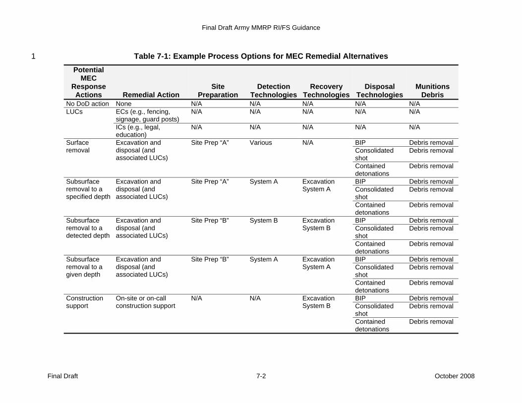
Final Draft Army MMRP RI/FS Guidance
Final Draft 7-2 October 2008
Table 7-1: Example Process Options for MEC Remedial Alternatives 1
Potential MEC
Response Actions Remedial Action
Site Preparation
Detection Technologies
Recovery Technologies
Disposal Technologies
Munitions Debris
No DoD action None N/A N/A N/A N/A N/A LUCs ECs (e.g., fencing,
signage, guard posts) N/A N/A N/A N/A N/A
ICs (e.g., legal, education)
N/A N/A N/A N/A N/A
Surface removal
Excavation and disposal (and associated LUCs)
Site Prep “A” Various N/A BIP Debris removal Consolidated shot
Debris removal
Contained detonations
Debris removal
Subsurface removal to a specified depth
Excavation and disposal (and associated LUCs)
Site Prep “A” System A Excavation System A
BIP Debris removal Consolidated shot
Debris removal
Contained detonations
Debris removal
Subsurface removal to a detected depth
Excavation and disposal (and associated LUCs)
Site Prep “B” System B Excavation System B
BIP Debris removal Consolidated shot
Debris removal
Contained detonations
Debris removal
Subsurface removal to a given depth
Excavation and disposal (and associated LUCs)
Site Prep “B” System A Excavation System A
BIP Debris removal Consolidated shot
Debris removal
Contained detonations
Debris removal
Construction support
On-site or on-call construction support
N/A N/A Excavation System B
BIP Debris removal Consolidated shot
Debris removal
Contained detonations
Debris removal
Final Draft Army MMRP RI/FS Guidance
Final Draft 7-3 October 2008
or after a response when cleanup to a level that allows for either unrestricted use 1 is not possible. Because some MEC might not be detected or removed during a 2 response, some form of LUC is normally required to address any residual 3 hazards that might exist. LUCs may be a component of other remedial actions, 4 unless leaving MEC in place proves to be the most favorable risk management 5 decision (e.g., due to technical or economic limitations, concerns regarding 6 worker safety, to prevent collateral ecological injuries) (U.S. Army, 2004a). The 7 DoD Policy on Land Use Controls Associated with Environmental Restoration 8 Activities (2001b) provides additional information concerning LUCs and 9 discusses the evaluation of unrestricted land use and unlimited access versus 10 LUCs during an FS. 11 12 The primary LUC mechanisms for MEC are defined below: 13
• Physical mechanisms encompass a variety of engineered remedies that 14 reduce or eliminate potential exposure to MEC known or suspected to 15 be present. Such controls are intended to limit or prohibit access to an 16 MRS, warn people of the potential dangers known or suspected to be 17 present at an MRS, or prevent the potential for MEC to migrate from the 18 MRS. These mechanisms are also known as physical controls or ECs. 19
• Legal mechanisms used for LUCs may be the same as those used for 20 ICs, as discussed in the NCP. These mechanisms are imposed primarily 21 to ensure that restrictions on land use, developed as part of a remedy 22 decision, stay in place. Examples of legal mechanisms include updates 23 to the Real Property Master Plan and restrictive covenants, equitable 24 servitudes, and deed restrictions for transfer properties. 25
26 A primary objective of LUCs is to help manage risks/hazards present at the site 27 during the implementation of remedial actions, as well as any residual 28 risks/hazards after the completion of active remedial actions. LUCs also ensure 29 that current and future land use is compatible with the agreed upon land use that 30 was the basis for the evaluation, selection, and implementation of the response 31 action alternative. Because current technologies do not allow for complete 32 removal of all MEC, LUCs are a component of nearly all munitions responses to 33 MEC. At active installations, the Army is responsible for maintaining LUCs. 34 35 At MRS where a use restriction is part of munitions response to MEC, the LUC 36 must be clearly defined, established in coordination with affected parties, and 37 enforceable. Implementing LUCs through established real estate and land use 38 management mechanisms provides a means to help ensure LUCs remain 39 associated with the land upon transfer of ownership. Use of a system of mutually 40 reinforcing controls is often a necessary component in a LUC strategy. When 41 considering LUCs as part of the response alternatives, the unrestricted use 42 alternative must also be considered. 43
Final Draft Army MMRP RI/FS Guidance
Final Draft October 2008 7-4
7.1.2.1 Active Installations 1 In the case of an active installation, 2 risk management responsibility is a 3 command responsibility, installations 4 should incorporate LUC into the 5 installation’s Master Plan (part of the 6 environmental overlay and an annex 7 with descriptions of both ECs and ICs) 8 (AR 210-20). In addition, if 9 appropriate, installations should 10 develop written management 11 procedures for maintenance and 12 inspection of ECs and review of proposed actions that may impact the LUCs 13 (e.g., construction projects, excavations). 14
7.1.2.2 Transferring Properties 15 When a property is transferring from federal control, the transfer documents 16 should specify the responsibility of the transferee and any subsequent property 17 owners with regard to maintenance and enforcement of LUCs. At properties 18 transferring from federal control, the Army should use state LUC registries where 19 available. The Army may, upon transfer, grant a property interest to the relevant 20 state or local agency, allowing the state or local agency to maintain and enforce 21 the LUC. Most LUCs at transfer sites would also be memorialized as deed 22 restrictions or in other publicly available legal instruments. The Army may work 23 together with state or local government agencies or with other appropriate 24 authorities (e.g., zoning boards) to assist in LUC management and enforcement, 25 ensuring compliance with remedial LUCs by a transferee. It is essential the Army 26 consult state property law and state environmental law when drafting the 27 restriction because state law may require the use of a particular type of 28 instrument or operative language. 29
7.1.2.3 Transferred Properties 30 For property transferred with some type of LUC, proprietary mechanisms may be 31 used to restrict land use. Proprietary controls are contractual or real estate 32 mechanisms, usually established in a transfer deed or contract for sale in the 33 form of covenants or easements. Such proprietary LUCs may be supplemented 34 with existing forms of control imposed by a state or local government originating 35 from their police power authorities. This may include zoning, permitting, and local 36 redevelopment ordinances. However, the Army cannot impose or enforce these 37 forms of governmental restrictions. Instead, the Army can work together with 38 state or local governments to ensure zoning and other forms of restrictions are 39 maintained. LUCs should be incorporated into appropriate transfer 40 documentation. The LUCs should be managed and maintained at the local level 41 whenever possible. 42 43
Long-Term Remedy Effectiveness: When evaluating LUCs, the MR Project Team should consider the long-term effectiveness and efficiency of the remedy. Therefore, clear plans and procedures to ensure the LUCs remain in effect and are enforced are important considerations for regulatory and stakeholder review.
Final Draft Army MMRP RI/FS Guidance
Final Draft October 2008 7-5
Approaches to LUC documentation differ between property owned/controlled by 1 the Army and property not under the control of the Army. Active installations 2 cannot use restrictive covenants or negative easements to restrict property 3 because these restrictions cannot be created without a conveyance. 4 Furthermore, federal real property policy generally does not permit creation of 5 restrictive covenants or negative easements by a land holding agency, such as 6 the Army. As a practical matter, even if these restrictions could be placed on 7 active installation property, restrictive covenants would not be effective for 8 notifying installation personnel of the existence of LUCs because they are 9 recorded in the local land records office, and title searches typically are not 10 performed when making land use decisions at active installations. However, state 11 law may permit alternative means of recording, such as a LUC notice, so 12 installation representatives should consider state real property law when 13 approaching this issue. A LUC notice may not create or convey a property 14 interest (U.S. Army, 2004a). 15
7.1.3 Remedial Action with Long-Term Management (Surface and 16 Subsurface Excavation and Disposal) 17
7.1.3.1 Surface Removal and Disposal 18 A surface removal is the removal of any MEC visible in part or whole on the 19 surface. A surface removal may be based on a visible survey of an MRS or may 20 be technology aided. During a surface removal, qualified personnel mark, 21 identify, and record the approximate locations of all MEC found on the surface for 22 subsequent destruction. In addition, all munitions debris and other materials 23 interfering with the geophysical investigation should be collected and stored for 24 later disposal (USACE, 2006a). 25
7.1.3.2 Subsurface Removal and Disposal 26 Geophysical investigations are performed to acquire data and identify all 27 anomalies beneath the surface. The data gathered is processed using 28 discrimination techniques to determine a dig list of those anomalies selected for 29 investigation. Whereas RI geophysical investigations are aimed at identifying the 30 presence or absence of MEC and, if present, the extent of the MEC, remedial 31 action geophysical investigations aim to identify all potential MEC-like 32 geophysical anomalies. The geophysical investigation phases are the same 33 during both the RI and the remedial action, but remedial action investigations 34 typically cover the entire site, while RIs typically only investigate a portion of the 35 site using one of the sampling strategies outlined in Section 5.2.2. Geophysical 36 investigations typically are performed in three phases. 37
• Phase 1: GPO (See Section 5.2) 38 • Phase 2: Geophysical survey – Employ geophysical instrumentation to 39
survey the MRS. Geophysical data are then analyzed and interpreted to 40 identify potential MEC for intrusive investigation. 41
Final Draft Army MMRP RI/FS Guidance
Final Draft October 2008 7-6
• Phase 3: Reacquisition of target anomalies for intrusive investigation – 1 All anomalies selected for excavation are physically reestablished by 2 precise survey methods, mapped, documented on dig sheets, and 3 intrusively investigated (USACE, 2000a). 4
5 Subsurface excavations and disposal methods for any MEC found are also 6 described in AR 385-10 Army Safety Program (2007b), AR 385-61 Army 7 Chemical Agent Safety Program (2003a), DA PAM 385-63 Range Safety 8 (2003b), and DA PAM 385-65 Explosive and Chemical Site Plan Development 9 and Submission (2008). 10 11 The design of remedial alternatives are based on land use and the potential 12 depth of any MEC that may be present. Potential interaction between receptors 13 and MEC are considered when designing a munitions response for MEC. 14 Currently, most anomalies selected for investigation are investigated to detection 15 depth. Other aspects that may be considered include the ability to store, destroy 16 or transport any MEC recovered. Storage and transport are discussed in EP 385-17 1-95a, EP 75-1-3 RCWM, and EM 1110-1-4009 (USACE, 2003l, 2004a, 2007). 18 19 Recovered MEC is normally destroyed on site, either at the location of discovery 20 or at the location on the MRS that has been sited and approved under Service 21 and DoD policy. In some cases, recovered MEC may be transported of the MRS 22 for destruction. The decision regarding the disposition of any MEC recovered is 23 based on the risk associated with the disposal operation, as determined by site-24 specific characteristics and the nature of the MEC recovered. Additional 25 information on MEC disposal operations can be found in TM 60A-1-1-31 26 Explosive Ordnance Disposal (U.S. Army, 1999). The MEC contractor shall 27 comply with the provisions of DoD 6055.9-STD, DoD Instruction 4140.62 28 (DDESB, 2008) and EM 1110-1-4009 (USACE, 2007) for the inspection and 29 certification of MPPEH. 30
7.1.3.3 Long-Term Management 31 LTM of an MRS where a munitions response to MEC will normally require some 32 level of LUCs, as described in Section 7.1.2, and recurring review of the 33 effectiveness of the response. Recurring reviews occur as part of the CERCLA 5-34 year review, but may be conducted at intervals less than 5 years if conditions at 35 the MRS have changed significantly (e.g., reasonably anticipated land use 36 changes from open space to residential). 37
7.2 Development and Screening of Alternatives 38 Alternatives identified in the FS are screened initially for effectiveness, cost, and 39 implementability. While the initial screening with regard to a munitions response 40 that only involves MEC (i.e., is not also addressing environmental contaminants, 41 including MC) may have limited utility, it may prove to be beneficial. This initial 42
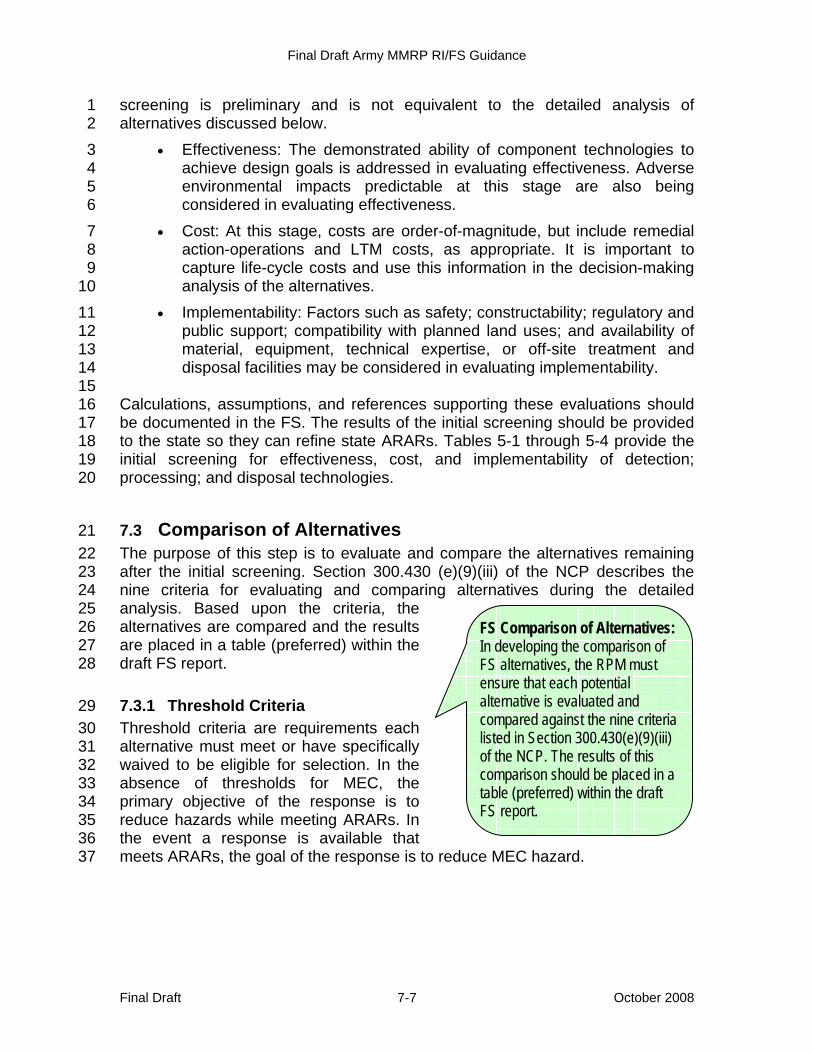
Final Draft Army MMRP RI/FS Guidance
Final Draft October 2008 7-7
screening is preliminary and is not equivalent to the detailed analysis of 1 alternatives discussed below. 2
• Effectiveness: The demonstrated ability of component technologies to 3 achieve design goals is addressed in evaluating effectiveness. Adverse 4 environmental impacts predictable at this stage are also being 5 considered in evaluating effectiveness. 6
• Cost: At this stage, costs are order-of-magnitude, but include remedial 7 action-operations and LTM costs, as appropriate. It is important to 8 capture life-cycle costs and use this information in the decision-making 9 analysis of the alternatives. 10
• Implementability: Factors such as safety; constructability; regulatory and 11 public support; compatibility with planned land uses; and availability of 12 material, equipment, technical expertise, or off-site treatment and 13 disposal facilities may be considered in evaluating implementability. 14
15 Calculations, assumptions, and references supporting these evaluations should 16 be documented in the FS. The results of the initial screening should be provided 17 to the state so they can refine state ARARs. Tables 5-1 through 5-4 provide the 18 initial screening for effectiveness, cost, and implementability of detection; 19 processing; and disposal technologies. 20
7.3 Comparison of Alternatives 21 The purpose of this step is to evaluate and compare the alternatives remaining 22 after the initial screening. Section 300.430 (e)(9)(iii) of the NCP describes the 23 nine criteria for evaluating and comparing alternatives during the detailed 24 analysis. Based upon the criteria, the 25 alternatives are compared and the results 26 are placed in a table (preferred) within the 27 draft FS report. 28
7.3.1 Threshold Criteria 29 Threshold criteria are requirements each 30 alternative must meet or have specifically 31 waived to be eligible for selection. In the 32 absence of thresholds for MEC, the 33 primary objective of the response is to 34 reduce hazards while meeting ARARs. In 35 the event a response is available that 36 meets ARARs, the goal of the response is to reduce MEC hazard. 37
FS Comparison of Alternatives: In developing the comparison of FS alternatives, the RPM must ensure that each potential alternative is evaluated and compared against the nine criteria listed in Section 300.430(e)(9)(iii) of the NCP. The results of this comparison should be placed in a table (preferred) within the draft FS report.
Final Draft Army MMRP RI/FS Guidance
Final Draft October 2008 7-8
7.3.1.1 Criterion for Protectiveness of Human Health and the Environment. 1 The overall protectiveness is a combination of the magnitude of residual risk / 2 hazard following the action and the short- and long-term effectiveness of the 3 alternative. 4 5 The hazard/risk assessment tool (upon DoD and Army acceptance) and the 6 USACE OERIA, as discussed in Section 5.5, provide input to the threshold 7 criteria of protection of human health and the environment. These tools can be 8 used qualitatively to evaluate the relative protection allowed by the remedial 9 alternatives. 10
7.3.1.2 Compliance with Applicable or Relevant and Appropriate 11 Requirements 12
See Section 4.1.4 for a discussion of ARARs. RPMs should consult their 13 organization's legal counsel for guidance on ARARs. 14
7.3.2 Balancing Criteria 15 Balancing criteria are those that form the basis for comparison among 16 alternatives that meet the threshold criteria. 17
7.3.2.1 Long-Term Effectiveness and Permanence 18 Long-term effectiveness considers the magnitude of residual risk/hazard, the 19 adequacy of the response in limiting the risk/hazard, the required LUCs, and 20 LTM. 21
7.3.2.2 Reduction of Toxicity, Mobility, or Volume through Treatment 22 This is a balancing criterion and assesses the degree to which response 23 alternatives employ recycling or treatment, reducing toxicity, mobility, and 24 volume. Toxicity, mobility, and volume are factors that can be addressed for MC. 25 For MEC, the toxicity and mobility factors are not specifically relevant. Therefore, 26 the reduction of volume, or removal of MEC, is the primary factor for MEC. 27 Remedial alternatives, at a minimum, address the principal potential threats 28 posed by the site to the local environment. Considerations for the evaluation of 29 this criterion are as follows: 30
• Disposal processes for MEC 31 • Amount of UXO, DMM OR MC to be destroyed, treated, or recycled. 32
The management of the MPPEH, and the disposal of material 33 documented as safe or documented as potential explosive hazard. 34
• Degree of expected reduction in toxicity, mobility, and volume, including 35 the means by which the principal threat is addressed 36
• Degree to which the alternative is irreversible 37
Final Draft Army MMRP RI/FS Guidance
Final Draft October 2008 7-9
• Type, quantity, or volume of residuals that will remain, considering the 1 persistence, toxicity, mobility, and propensity to bioaccumulate 2
• The degree to which the alternative reduces the inherent hazards posed 3 by the principal threat 4
5 When conducting these analyses, decision makers need to consider the multiple 6 sources possibly generating waste during a munitions response (removal or 7 remedial) and prioritize the associated concerns (i.e., UXO, DMM or MC) for (a) 8 MEC (explosives safety), (b) MC and incidental non-munitions contaminants; 9 and, (c) MPPEH (explosives safety). When evaluating response alternatives 10 against the reduction in toxicity, mobility, and volume criterion, consider the 11 degree to which the response alternative will address any MEC present and treat 12 any environmental contaminants, including MC, present. In certain situations, the 13 removal of MEC may effectively remove any MC contamination present. 14 Confirmation sampling following the removal of MEC will help determine where 15 any additional MC treatment is required. 16
7.3.2.3 Short-Term Effectiveness 17 Short-term effectiveness considers worker and community safety, as well as 18 ecological impacts, socioeconomic impacts, and cultural impacts. Worker and 19 community safety is addressed through ECs and ICs established during the 20 remedial action (e.g., EZs, PPE). Ecological impacts vary with site-specific 21 conditions and alternatives (e.g., surface vs. subsurface removal). For example, 22 alternatives requiring a high level of vegetation removal have a larger impact 23 than those not requiring such removal. The evaluation of socioeconomic impacts 24 requires decision makers to conduct an analysis to determine if environmental 25 justice is a concern or potential concern. To conduct this analysis, decision 26 makers should evaluate impacts or potential impacts of each alternative on 27 minority and low-income communities living on or near the MRS. Examples 28 include how a response alternative would impact low-income communities versus 29 affluent communities or how subsistence farming or fishing patterns relate to the 30 response alternatives. 31
7.3.2.4 Implementability 32 Implementability can include technology and administrative requirements. 33 Examples of each are given below: 34
• Technical requirements 35 ° Access due to terrain, vegetation, soils, water, hazards 36 ° Availability of technology 37 ° Availability of equipment 38 ° Meteorological/climatological concerns 39 ° Available technology 40

Final Draft Army MMRP RI/FS Guidance
Final Draft October 2008 7-10
° Ability to determine effectiveness 1 ° The ability or inability to integrate munitions responses with other 2
environmental responses 3 • Administrative requirements 4
° Legal considerations 5 ° Coordination and time requirements 6 ° Access due to ownership 7 ° Personnel/equipment shortages 8 ° Funding availability 9 ° Contracting existing mechanisms and capacities 10
7.3.2.5 Cost 11 This is a balancing criterion used to evaluate the capital cost, annual O&M cost, 12 and net present value costs associated with implementing each alternative with 13 consideration of discount rates over a 30-year period. The 30-year period 14 adopted in this document is consistent with the NCP and does not represent a 15 limitation on the length of response implementation (EPA, 1991a). It is used in 16 this context for subsequent use during the comparative analysis to evaluate the 17 differences in costs among alternatives. As such, the cost estimates need to be 18 revised prior to the end of the original O&M period. 19 20 When conducting the analysis of individual response alternatives, decision 21 makers should compare net present value costs associated with implementing 22 each alternative. In addition, Guidance for Conducting Remedial Investigations 23 and Feasibility Studies Under CERCLA (EPA, 1988 and 1990) indicates that 24 order-of-magnitude cost estimates having a desired accuracy of -30% to +50% 25 should suffice for the more detailed analysis of response alternatives for this 26 criterion. 27
7.3.3 Modifying Criteria 28 Modifying criteria are criteria considered in remedy selection. 29
7.3.3.1 Regulatory Acceptance 30 Dialogue among members of the MR Project Team should be maintained 31 throughout the process. However, formal evaluation of this criterion should 32 precede remedy selection, which is the final step in the detailed analysis of 33 response alternatives. 34
7.3.3.2 Community Acceptance 35 Community acceptance may be estimated based on community outreach efforts, 36 but this criterion should be the last phase of the process prior to remedy selection 37
Final Draft Army MMRP RI/FS Guidance
Final Draft October 2008 7-11
and cannot be fully evaluated in the RI/FS phase. Community outreach efforts 1 include, but are not limited to, the development of the CRP, RAB meetings, 2 public meetings, and other widely accepted mechanisms. 3 4 The detailed analysis provides the means by which facts are assembled and 5 evaluated to develop the rationale for a remedy selection. Therefore, it is 6 necessary to understand the requirements of the remedy selection process to 7 ensure that the FS analysis provides the sufficient quantity and quality of 8 information to simplify the transition between the FS report and the actual 9 selection of a remedy (USACE, 2006b). 10 11 Final community acceptance is evaluated when the Proposed Plan has been 12 issued and the public meeting / comment period for the Proposed Plan has been 13 conducted. Public/community concerns are then addressed in the selection of the 14 remedy in the final ROD/DD, and responses are provided in the responsiveness 15 summary section of the ROD/DD. 16
7.4 Reporting 17 The FS portion of the RI/FS report should summarize the results of the RI, detail 18 the development of ARARs and resulting PRGs and remedial action-operations, 19 identify and screen the general response alternatives, provide detailed alternative 20 descriptions, and provide a comparative analysis of the response alternatives. 21 Appendix D provides an outline of the RI/FS report and example presentations of 22 the content. 23
24