final report dir&ct prime andkelded platetixts “ ; … · prime andkelded platetixts “ ; by...
TRANSCRIPT

DIR&CT
FINAL REPORT
on
EXPLOSION TEST FOR M2LDED ARMOR AND SHIP PLATEPRIME AND KELDED PLATE TIXTS “ ;
by
WILLIAM A. SNIQWINGTROJAN POWDER COMPA~
Under Navy~Contract NObs-31223
CWtITTEE ON SHIP CONSTRUCTIONDIVISION OF ENGINEERING & JN)USTRJ!ALR.WE)4RCH
~ NAT~ONAL’R&SEARCH COUNCIL
1
Advisory to.,
B&U OF SHIPS, NA~ DEPARTMENTUnder.,Contractl@bs-34231.
&wiai No. SSC-4
August’30:1:6
copy No.Js., , \

August 30, 1946
Chief, Bureau of ShipsNavy DepartmentWashington 25, D. C.
Dear Sir:
Attached is Report Serial No. SSG4, entitledl!Di~e~t ~Plosion Test for ,~eldedArmor and Ship plate: priMe
and Welded Plate Tests!t. This report has been submitted bythe contractor as the final report on work done on ResearchProject lJhC-25under Contract No. NObs-31223 between the dureauof Ships, Navy Department and the Trojan Powder bmpany.
The report has been reviewed and acceptance recom-mended by remesentatives of the Committee on Ship Construction,division of engineering and Industrial Research, NRC,accordance with the terms of the contract between theof Ships, Navy Department and the National Academy of
Very truly yours,
inBureauSciences.
Chairman, Division of Engineeringand Industrial I&search
.unclosure
.– —-——

PREFACE.— . .
The Navy Department through the Bureau of bhips is distributingthis report to those agencies and individuals that were actively associatedwith this research program. This”report represents a part of the &esearCh!work contracted for under the section of the Navy’s directive “to investigatethe design and construction of welded’steel merqhant vessels”.,. . .
The distribution of this report is as follows:
Jopy No, 1 -copy M+ 2 -
Zopy No. 3 -copy No. ../+-copy Xo. 5 -Uopy No. 6-Copy No. 7 -ti~y NO, 8 -copy No. 9 -Copy No, 10 -Copy No. 11 -
copy No. 12 -copy Jo. 13 -copy NO. 14 -Copy No. 15 -copy No. 16 -copy No. 17 -copy ]JO.18 -copy No. 19 -Jopy No. 20 -copy No. 21 -copy ~0. 8 -:Opy No. 10 -
copy Lo., 1 -Jopy No. 22 -cOpy iiO.23 -copy No. 24 -copy No. 25 -COPY NO. 26 -COpY iio.27 -copy :’jO.28 -COPY No. 29 -Copy No. 30 -
Chief, Bureau ofJr. D. W. Monk,
Interim bhip
. .
Ships, Navy DepartmentChairman, National Research Council
k
Structure Sub-Committee
Captain L. V. Honsinger, USN, Bureau of Ships, ChairmanCaptain ii.P. Roop, USN . .
Commander d. D. Schmidtman, USCGLt. Comdr. J. k. MacCutcheon, USCCH3(T)David ?, Brown, American dureau of ShippingJohn Vasta, U. S. iiaritimeCommissioni. J. Wanless, U. b. Maritime GcmmissionJ. L. dilson.,American bureau of ShippingFinn Jonassen, Liaison Representative, NRC
Members of Advisory Cormittee of Research ProjectssR-92, W-93 and SR-96
J. b. Qikhalapov, chairmanJavid ArnottJ. -. datesH. C. BoardmanPaul Ffiel.dC. H. Herty, Jr.b. L. HoytA. NadaiH. ‘d.Pierceti.C. WthJohn Vasta ,..J. ~. “i~ilson
Navy Department
Vice .dqdm.l &S L, Cochrane, USN, Bureau of ShipsComdr. R. H. Lambertj USN, Bureau of ShipsGomdr. R. S. kandelkorn, USN, Bureau of ShipsJomdr. J. H. Mc@lkin, USN,’tiureauof ShipsA. G. Bissell, Bureau of Ships ,,
=, T. khrrison, Bureau of tihips .
E. Rassman, Bureau of ShipsR. A. ;~iley,Bureau of bhips ,.
K, D, ‘Jilliams,Bureau of ShipsNoah Kahn, Hew York Naval bhipyard

Copy Nof 31 -COPY ;lO132 -copy NO,.33 -Copy NQ4 34 -Copies No. 35
Copie~ No. 37
copy iuo,39 -Gopy No. 40 -copy No. @ -copy No. 42 -
copy No. 43 -Copy No. ~ -
copy NO. 45 ‘-
COPY No. 46 -copy k. 17 -copy No. a -
copy No. 47 -copy i’~oe4$ -copy iJo.49 -copy ;?0,50 -
Copy No. 51 -
COpY ::0.52 -copy No. 53 -copy No, 11 -copy A’lo.54 -copy No. 55 -~Opy NO, 56 -:Opy l%. 57 -copy AO. 58 -Copy No. 59 -
Navy Department (conttdj
... d. Osgood, David Taylor kodel dasiriF..M. dobertson, Office of Research and InventionsNaval Research LaboratoryPhiladelphia Xaval ShipyardL36-
&3b-
Publications doard, Navy Department via Bureau ofShips, code,330cTechnical Libraryj Bureau of Ships, Code 337-M
J. S. Coast Guard
dear.lktairaldl.1.isRee~-H+llj USCGCaptain d. d. Qnk, Jr., USCGComdr. P. A. Ovenden, USCGRs. Jo Lank
U. b. Maritime Commission
Captain T. L. Schumacher, UtiN ,-‘ h. Martinskyd, ,.
Representatives of American Iron,and Steel InstituteCommittee on manufacturing Problems
C. k. Parker, Secretary, General Technical Committee, AmericanIron and Steel Institute
=. C. Bibber, Carnegie-illi.noisSteel CorporationC. H. Herty, Jr., tiethlehembteel ~ompanyd. C. Smith, Republic Steel Corporation
Lem’oersof the “’jeldStress Committee‘JeldingResearch Council
Everett Chapman, Chairman4, A. Adams&Motte Grover,iilliamSpraragen
Jean F. M. Feiker, Chairman, Division of .ingineeringandIndustrial Research, NRC
Jr. Clyde ‘killiams,Chairman, Comnittee on Engineering LaterialsV. H. Schnee, Chairman, Committee on Ship ConstructionFinn Jonassen, Research Coordinator, Committee on Ship Construction;~m.A. Snel.ling,Investigator, hesearch Pxmject NRC-25T. R. Cuykendall, Investigator, fiesearchproject SR-89 ..H. L. Davis, Investigator, Research Project SR-924. Paul DeGarmo, Investigator,Research project SR-92k:.Gexxxner, Investigator, .ie$earchProject SR-96S. R. Parker, Investigator, Research Project SR-92

Copy No. 60- lJ.M. ‘Nilsori,Investigator, fiesearchProject W-93Copy No. 61 - A3hrt Miller, Investigator, NObs-3&32COPY NO, 62 - ‘.:.o.Copies 63 thru 67 -
bpy do. 68 - U, S.
Snellingj Director of”desearch, Trojan Powder CompanyIi.braryof Congress via Bureau of Ships, Code 330c,Navy DepartmentNaval ~gineering Experiment Station
Copy No. @ -copy No, ‘?’0-Copy i~o.71 -COpX NO. 72 -copy No* 73 -copy ;~o,74 -‘copyIqo+‘/5-Copy NQ, 76 -Copy Nu~ 77 -copy No; ’78-Copy No. 79 -copy No. 80 -Copy No. gl -Gopy No. 82 -Copy ~~0.83 -copy No. 84 -copy No. 85 -Copy No, %6 -Copy No. @ -copy No. 88 -Copy No. 89 -dopy No. 90 -copy No. 91 -copy NO. 92 -Copy No. 93 -Uopy No. 94 -Copy No. 95-COpJrNO. 96 -copy No. 97 -Copy ifo.98 -Copy No. 99 -copy 110.100-
(Copies 69 thru 100- Bureau of Ships)
Total Nunber of Copies - 100
-.—
FINAL REPORT ‘
TO THE
NAVY DEPARTMENT
BUREAU OF SHIPS
NObs-31223
.
DIRECT EXPLOSION TdST FOR WELD@ ARMOR AND SHIP PLATE●
PRIME AND WELDED PIATE TESTS
Report Prepared by
William A. Snelling
Trojan Powder Company
ld.lentown~Pa.
January, 1946

NJMWRY
Direct Explosion Test for Prime and hblded Steel Plate
1. The direct explosion test has been reduced to practice and itsability to determine the relative resistance to multi-axial shock loading ofprtie or welded steel plates with reproducible accuracy has been demonstrated.
(a) Tests to compare butt-welded steel plates intneas-welded condition with similar welded specimens, which had been stressrelieved using the low temperature stress relief method, have been performed.
(b) Tests to compare butt-welded steel plates in the as-welded condition with similar welded specimens some of which were flamestress relieved and some of which were furnace-stressrelieved have beenperformed.
2. An investigation ‘.vasconducted to ascertain whether or not it waspossible to reproduce by shock loading in 0.02511thick specially-treatedmateria~ the extent and distribution of deforr,ationproduced in 0.5’1thickmedium steel plate subjected to the explosion test.

Final.Report
Navy Department Bureau of Ships NO’OS-31223
TABLE,,PFCOIV~.~
.Abstract
I. Introduction.....*! .o.*.*ooo**D** ● *9
11. Results and Discussion . ● . ● . c ● ● ● ● ● ● Q ● Q * ● ● ●
A. Tests Comparing As-Welded with Stress Relieved Butt-WeldedShip Steel Specimens . . . . . . . . . . . . . . . . . .
B. Tests Comparing As-Welded with Several Types of StressRelieved Butt-Welded Steel Specimens . . . . . . . . . ●
C. Testing of 0.025flThick Specially-Treated Steel PlateUtilizing Explosives . . . . . . . . . . . . . . . . . .
111, Conclusions . . . . . . . . Q ● ● ● ● ● ● ● ● ● ● ● ● ● ● *
IV. Illustrations:
Figure 1 -t!11II
II
II
II
II
Base Plate and Test Set-up . . . . . . . . . . .75 mm. Standard Density Apparatus Assembled . . .75 mm Standard Density Apparatuslkisas_@. .Initiating Device. , . . . . . . ● . T ● ● ● ● ●
Typical Longitudinal Stress Pattern of anAs-WeldedSpecimen . . . . . . . . . . ..o. .Typical Longitudinal Stress Pattern of a StressRelieved Plate , . . . . . . . . . . . . . . . .H.T.S. Plate Showing Typical Transverse WeldFailure . ..0. ● *O*.* ● ***
Apparatus ~o~ ~e~t~ng Thin Steel Specimens in aHydraulic Medium . . . . . . ,. . ● . Q . ● ● ●
~
1
3
3
7
9
u
12
E15
16
17
18
19

Abstract
The direct explosion test has been utilized to determinethe relative resistance of welded and unwelded steel spectiens toshock loading. The tests were conducted using a special explosivewhich is detonated in direct contact with the spectien under controlledconditions. Repetitive tests have demonstrated the excellent repro-ducibility of the test.

-1-
DIRECT EtP&OSION ~ST FOR PRIME Al@ WELDED PL&TE
I. Introduction.—.
A. During the period cotiere~by this report, the direct expl-osiontest for prine and welded plate has beeh r,educedto practice, i.e., specimenshave been submitted for testing and the ~esults of such tests have been usedas an index of structural performance of tiarious’specimens subjected to severeloading conditions. - .
3. Possible methods ofsheet by means of explosives were
$. A discussion of each of
..,,
shock testing 0.025!Istudied.
the studies outlined
specially-treated
above follows the
steel
de-tails of the experimental equipment and explosive characteristicsbelow:
i,,
Orizinal.tests indicated that a firm base on which the spectien andrelated supports could be placed for testing was necessary and that ~ertaininaccuracies could thereby be eliminated. The base shown in Figure 1 (Photo-graph B-63) has proven satisfactory and con$ists of an eight foot square blockof reinforced concrete fifteen inches thick and which rests on abed of well-compacted cinders. Two pieces of steel, t~~ lower 3!!thick and the upper lttthick, weigh a total of approximately 2,500 lbs. and are placed bn top of theconcrete. The top piece of steel is easi~,~replaced if it becomes damaged,
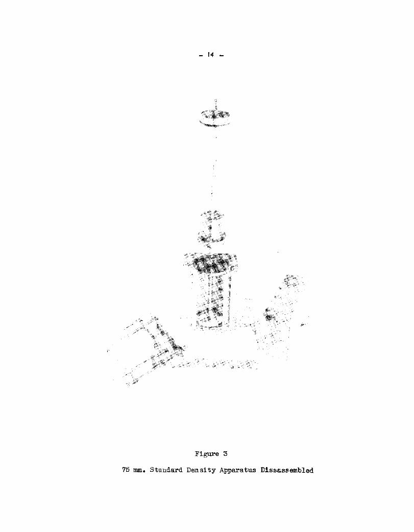
Original tests indicated that #’@h the physical shape of the explo-sive charge and the type of explosive chb~ge must be controlled. A cylindricalpellet was found to be desirable and a device known as a Standard Density Appara-tus, develo~d by the Trojan Powder Com~any a number of years ago, was found tobe readily adaptable to the making of #uStable pellets ”withthe testing explo-sives used.
[
Several modifications of the Standard Density Apparatus have beenmade, one of,which is shown in Figures z and 3. These figmes illustrate the
‘“ equipment sp~cifically adapted to m~e pellets 75 mm in diameter,,>, With thisapparatus the density of the explosiveichargecan be controlled within certainlimits at will, and densities have been consistently rcproducedwith a varia~tion of less than 1%. Figure 2 shows ,~heapparatus completely assembled andready for use, while Figure 3 shows tlfeapparatus disassembled.
,{
The type of explosive requi~ed has been found to be influenced by.the,.
particular steel specimens being inv<$tigated, so that a number of specializedexplosives have been formulated to m+bt the variousnpeds, and @ all cases thecharacteristics of the testing explo,@ivesare measured by subjecting thdrn.to,anumber of tests, the most important if which are the ballistic pendulum testwhich is an index of the gas volume, the rate of detonation test which measuresthe speed of the detonating wave, aridthe standard density test which measurestho density under standardized conditions. ~ ,,
After the physical shape of the charge and the type ofexplosive hadbeen decided upon, an initiator was designed so that the charge could be usedwith greatest effectiveness (Figure 4). This initiator is,placed an top of eachcharge of explosive and consists of a ring about 1-1/21!in diameter of Ensign-Bi,ckforlPrimacordand a pi~ce extending across the center of the ring, both of
,,,.
,.

-2 -.,.
which are firmly attached to a small.wooden block. One endlengths of Primacord is bent in the form of a semicircle tothe opposite end of one is twisted several times around the
of each of twomake the ring, andextending portion
of the other. The detonator is attached to this upwardly extending part.
When the detonator is fired, the length of Piimacord is caused todetonate which in turn detonates thq explosive charge. The flat ring $s placedso that its entire circurrife~en,cemakes contact with the’top ,ofthe explo~iv~,charge. Since the detona+iQn of the charge takes place around.its c~rctieren~e,instead of from one spot ~kich would be the case when a detonator alone is used,the detonation wave travels practically in a,straight downward direction..,,,, ,l;’;:,.,~,,,, ,’ ,’,
Thequant+ty of ’explosivecontained in this initiator is approximately2.89 grams, ~d the:~ount”of e~~lmsive actually touching,the explosive.chargeis only abdut’1,18 ~rh’s~ ‘ ““4
,.,L,,.: ‘$’;;
Onthe basis of the resqlits.obtainedwith this initiator, it appears tobe a definite improvement oveb th~use:;of a detonator alone. .’., ,,.,:~..,.
It is of utmost.importah~~,to have thoroughly in mind the fundament~characteristics of an explosivi,fi~~rderto understand or control its effects.These fundtientals were use~’ak;a Atartlng point for the formulation of a specialtesting explosive to be used in this research project. From past experience the ,effects ~f:bxplosiv~a,havebeen conveniently.classifiedinto brisant effects andgas volume effectsl the ‘inter-relationshipof which can cause any of the infinitenumber of variations,..~nthe types of shock produced by explosive action. It isentirely true, hqwevqr, that this distinction is not entirely a physical one, andthat there is a little overlapping in the two types of effects.
,-,.: ..
A highly brisant explosiv~ (that is;,,
one with a rapid rate of detona~~on).’,~,,will produce a very shattering and destr~ctive b~oy which is many tines ‘character-ized by a’spall or a hole when an,arrngr.plate is sub~ected‘tosuch-a shock. In “ “ “’contrast, a I!slowl!explosive or’’one.~t~!lowbrisanc”e(low rate of detonation) ., “tends to move or ~ef,orm@t,erial in it~ ‘vici@ty. A dish or cup-shaped indenta~.tion is likely to be the,,resultof tJie~@Lication of such an explosive forceagainst steel plate, depending on how,?}@the rate~of detonation is,.andthetype of steel.
,. :/ ,4 ,.,,!.,- ...,,
,1,A very good an~~”of the rat~jof detonation tid gas volume of an ex-
Yplosive can be found inba.~istics. in $,1#$speed and mass,of the projectile whenin flight. The sp@ed of thetprojd~~,,~,~
P
~:~~ be likened to ,therate of detonationof an explosive, while the mass of t e projectile can be’likened to the gas volume.It is known that a projectile must have a certain mass in combination with itsvelocity in order to penetrate a plate, and similarly an explosive must have asufficiently high gas volume @ order to have sufficient force with which to per-form the particular task desired. Just’as the weight and speed of a projectilecan be”varied within ,widelimits in accordance with specific requirements, so canan explosive be formulated to have almost any combination of rate of detonationand gas volume within reasonable limits that are desired.
From previous experience it was decided,that in order to produce morefldishinglrand leSS ‘tsp~ingtt in the specimens tested by the direct applicationof an explosive shock, the explosive to be developed.would have to have’a tom-’paratively low rate of detonation and sufficient gas volume. ‘.
.

-3-
A number of experimental explosives were formulated and tested bymethods then in use which included rate of deto,nati.ontests, standard densitytests, gas volume tests, afidsmall lead block tests, and also by actual testson steel plates. Several of the explosives made produced satisfactoryhullplate deformation, and finally and experincntal explosive designated as NS-D ‘was adopted as being the most promising. !lhisexplosive contains trinitrotolueneas its basic explosive ingredient, with ammonium nitrate and sodium nitrate ascooperating oxidizing salts as well as several other chemical components, Notonly are the proportions important, but it was learned that the particle size andthe intimacy.of tiure are significant factors in obtaining reproducible results.
NS-D”explosive is a dry, pulverulent powder with a density of about‘1.16(water = 1.00), a rate of detonation of approximately 2200 meters per second,and a gas volume of 10.5 (TNT standard = 10.0).
Additional detail$ of the testing procedure, experimental equipment,and explosives used in these tests are presented in a series of earlier reports,(Final.Report - Part I.,OSRD No.4655, Serial No. M-446 dated 23 January 1945;Final.Report - Part II; 0~ No.!63$2, Serial No. M-622 dated 5 December 1945).
,,
11. Results and Discussion.’ ~~
A. Tests Comparing As-”@’ldedwith Stress Relieved Butt-Welded Shi@Steel Specimens.
A group of twenty 18’:x 18’)x3/4f1 butt-welded spec~~ns~ ten of whichwere in the as-welded condition, and ten of which were stress r’elieved,weretested using the,direct explosion test to determine whether stress relievingaffected the resistance to shock loading. The stress relieved specimbns wereprepared using the low temperature method of stress relief which involves theheating of the metal on each side of the weld and parallel thereto (by’s movingflame to a temperature not over 400%?), while at the same time cooling the welditself with a stream of water, The temperature differential causes plastic flowin the weld thereby reducing the residual welding stress.
These tests wertirequested by the U. S. Coast Guard. No unwelded speci-mens were furnished
The steel used to prepare these specimens was of the rimned type and wasprocured from the Worth Steel Co. The chemicsl analyses and mechanical propertiesof this steel are listed in Table I:
TABLE I
‘Chemical AnalysisMelt No. ~ No. ~ #l_ &
6-?3983 3 O*U3 0.43 O,oa
,.. ,,:,’ ,,,
,,,’,
in% .,.,.~0.025
Yield Tensile StrengthTest Piece Point I+bs. Lbs. per Square % Elonga-
Thickness Sec.Area per Sq. In. Inch tion in 811——
0,738’1 1*122 Sq. 37,7W 59,500 32~7inches
——
.. , ,.,
., ...”. ,; .-..4 ,,- ,,...lkch.specimen vias”pkepared’byjoining %WO,$J1!x&ll x,.3/41t”piqqes,to-
gether us~g E 6QL0,electrod@”’with”bdouble-V~ 600 included,~Qei, @tt. weld’consisting ~ e,igh$passes,”‘after‘yhich’the weld reinfcn%emnt was,,~,,~fflovedpn‘one’side;of the pla~e. ,The“weldreitioieemnt”Within.:1-l/~\! of,.,e~ch,,,edge,of theplate was removed,on.the.oppo’site,s,tde,”sm that the.plate$ [email protected]~ [email protected] test. ,:, ~
: .,: .:,: ..’.,. J ‘: .,:,.!,-,......,(..
,.. , .,. .,, -.... .,,,
‘.Figure 5 sh~s a typical p16t of’the longitud~l’’stress’patternof’ !,., ..
,..
the as-welded spectiens.” F~g@e 6 shows d @6bof the longitudinal styesispattern in a typical stressr,~lievedplate, and also gives as a cou,parison‘the”’average stress pattqr~::hg~.:lnFigure “5~’Ir.additionj Figure 6 indicates thetemperature attained ak various’points;’:duringthe stress relieving process.
, .. .... ‘ .,’ .“..‘..
:;: The plates,were stored pr.or to testing in an insulated cabinet with+l@o(21+oc). ,: !the temperature “maintained’’at70°F -., .....””,,.,, .,. .,,,.
The powder char.~e;cc?n~is%’ed’ofM-D exp~osi,ve(Iot,5~6,B), and was,,
... .packed by means of a Stahdard’13ensityApparatus in 75 mm di~e~er paper cartons.In all tests except those on Plate lC, Specimen 1 and Plate lC,’Specimen 2, thecharge was prepared in two increments. In the aboyernentiormd two tests~ however,the charge,was prepared in three increments.
.,. ‘. ,,,.- ,,.
In general, each specimen’was supported by-:”ceqteringit on a @mmetri-cal IIpin..wheeltype!!support as showq in Figure 1, and’the explosive charge wascenteredo~ the weld at the center of the plate and wo@ined in an 8-1/2tldiameterx 12f~high,@aft c@on filled with’~approximately 35 ,lbs.of 2~30 mesh Ottawasand, a@ pas detonated by means of a #6”’fu.se.typeblasting cap attached tio~Primacord~itiator which was in juxtapositionwith the.top.of the expl~,s~vecolumn, all of,which is in conformity with the usual e,st,ablishedtesti~ procedure.Ih Figure.,1,a plateof glass is us.edinstead of:a,steel plate to showliemanner
;. of support. ,.,l?heout:ercotiming container is cu% away toshowthe Ottawa’sahd and “ .the explosive cylinder. The Prtiacord initiator.arid.the~use are also’’~hown.This symmetrical.method of support sinulates the ~,our-~idedsupport’~ktp “section
.. of a,platp recei~es from the plate surrounding it..,, .,!.,,
,. .,...,,In a few specific instances some parts of this general..’p~ocedurewere
:,: ,,
depar}ed fromz which are as follows:... .,, ;,. ,,
In til tists except those on Plate~4C,~~pe&im&n3 ~dPlate:4G,.Specimen 4, the distance between the suppo&tswas..16tt.~easyr~qg~rom the insideof a bar to the one parallel to it(. h the ease of those two spcc~ensi”thedistance between the supports was’10!land the charge was not centered on theplate and
!......’
—was placed on the~parent,metal... .’.’ ,
Specific data’for each tast,.isas follows: ~j,~:;;.’......,.””,,(.,.,..,...<,.,..’*i ,,, . ., *c ,..:,
:,.,..,,“,,:!,.1 ..,., ., i..,,.“;:
,.,’;,:-::,, ,’.: ,:.’,- :.....<..-.,,.-,!..,,..,,.. .!”,.,..--.-1.-,,’... .. . t’... ;“.’
●
.,.,,,,....... ,.,,,(: .,.. ,.. ,,,:,’ ,.
.. .

~5-
TABLE II,,
Test Specimen Total Charge Grams per No. of& Number Wt.,in Grams Increment Increments Results
NS-lW PIilCspec. 4
‘ASWELDED
1$0 90 2
2C0 100 2
200 100 2
205 102, 103 2
210 105 2
210 105 2
220 110 2
No failure. 57 mm dish par-allel to weld. 58 mm dishperpendicular to weld.
NS-188 PLIC spec. 5 No failure. 61 mm dish pati-allel to weld. 62 mm dishperpendicular to weld.
1$s-192p~C spec. 1 No failure. 59 mm dish par-allel to weld. 61 qm dishperpendicularto weld.
NS-200 PL3C spec. 5 i3rokein 4 pigces.
N&190 PL3C spec. 3
NS-194 PL3C spec. 2
NS-l@ PL3C spec. 4
Broke in 3 pieces.
Broke in 4 pieces.
Broke in ~ pieces.
230 115 2
280 94, 92, 94 3
330 I.lo 3
NS-186 PILC spec. 3 Broke in 4 or more pieces.1 or more not recuvered.
Broke in 3 pieces.NS-185 PILC spec. 2
NS-184 PLIC spec. 1 Broke in ~ pieces.
STRESS RELIEVED(using the low temperature method of stress”relief.)
105 2NS-191 PL2C spec. 4 210 No failure.,63-1/2 mm dishparallel to weld. 65 mm dishperpendicul,zirto weld.
No failure. 67M dish par-allel to.w.eld.,,70 mm dishperpendictiar”to weld. ,,
No ’failure.65 rmr,dishpapallel to weld. 67mm ti.shperpendicular to weld. ~
N&193 PL2C spec. 3 230 115 2
NS-197 PL2C spec. 5 230 135 2
232-1/2
235
240
250
250
SL6.25 2
117, 118 2
J.20 2
125 2
Broke in 5 pieces.NS-201
NS-199
Ns-196
NS-198
NS.495
PL4C spec. 5
PL4C spec. 2
PL2C spec. 2
PL4C spec. 1
Broke in 4 pj.ec:es.. :
Broke ti 5 piecesk
Broke in 4 pieces.
Broke in 4 pieces.PL2C Spec. 1 125 .2
..

:6-
TABLJiII(copt~d)Test Specimen Total Charge G=: No. ofNo. Number ~W. in Grams Incremeht. Increments Results-—
,,, ,. . . .
NS-202 PL4C spec. 3 230
Ns-203~.pL4c spec. & ~~240 ~.::.. ... .,.,:.:.. ,;’,,
All PUG and PL3Cwere ,flamestress.relieved:
,,.,,.: ..’..’. !•:,,J~,.,..”. “.$.,:..,. .
It can be seen in
115 ‘“ 2 No failure.,....,.,.
120 ‘2 Broke ~ ~ pieces. Consid-erable petalling.
plates were as-welded and all.PL2C ~d PuC plates
Table II that all charges of 205 grams or.rndre.causedfailure ii the as*w61c@q plates, whereas all charge= of 200 ~~ or less did notcause failude inthe as-welded plates. The as-welded plates are considered to havea breaking,$trengt h’r’a~+of:from 200 to 210 grams which has been consistently es-tablished with a double check both at 200 ~amsand at 210’grams\.
:.
All charges of,,232-1/2grams or more caused faikure in the stress re-lieved platiesjwhereas_all charges of 230 grams or less did not cause failure inthe stress relieyed plates. The stress relieved plates are considered to have abreaking st~ength range of from 230 to ~0 gr~s, which has been consistently es-tablished wjth a double check at both 230 gramsand 240 grams.
The term Ilbreakingstrength rangeltis used in this report to indicatethe maximum charge at”which no failure occurred and the minimum charge at whichfailure occurred. In some instances, a double check is used to bound the breakingstrength range.
Using the above procedure, the stress relieved plates require 30 gramsmore explosive charge to cause failure than did the as-welded plates..
It.is interesting to note that stress“relievedplate PL4C, specimen3which was tested with a 230 gram chsrge did not fail, and that stress relievedplate PI&~ specimen ’4’which was tested with a 240 gram charge did fail in view ofthe fact that both of these plates were tested following a different procedure ,fromthat followed ”forNS-l@ to NS-201. NS-202 (Plate P14C, specimen3) and 203 (PlatePL4C, specimen 4) were tested while the specimen was supported on the four sets ofbars plahed in a pin-wheel fashion with each set of parallel bars being 101I(inste~:of L61!)apart. The specimen was placed on the support bars so that each side of onecorner of the specimen was supported by a 11~portion of each of the two support bars,over which it rested. The other two supports were completely covered by the speci-men. The explosive charge was centered on that portion of the plate supported bythe bars, and therefore, its center was 611from each edge of the corner above men-tioned, and Consequently was not over or touchingthe weld. :’
Note: Some of the specimens exhibited a slight tiount of warping due to weldingand therefore,did not rest absolutely flat on the support barso
.
B. Tests Comparing As-Welded with Several T~e.s of Stre$s.Rel,ieved,Butt-Welded Steel Specime~.
-— ...—
The specimens discussed in this section are not comparable with thosediscussed in the pretri.oussection because of the difference in the stress re-lieving practice, and in view of the different type of steel used. The specimen.size is also different~
A group of eighteen 1211x 1211x 3/411butt-welded specimens were tes~cdto determine their relative resistance to shock loading as obtained by the diuectexplosion test. Six were in the as-welded condition, six were furnace stress re-lieved at ~500’F for one hour, and six were torch stress relieved by passing amultiple tip torch progressively over the weld bead on one side of the plate oul.:r(side on which weld reinforcement had been machined off). The weld metal reach.>da temperature of 9000F on the side opposite to the flame and this temperature wasmaintained for 10 -minutes. A fully killed, normalized steel was used to preparethese specimens+ This steel was furnished from Lukens Steel Co., Heat No. 20340,Slab No. 6, Plate No. lQ, and had the followtig chemical analysis:
TABLE 111
~arbon me= Phosphorous sulfur Silicon Q12SL
0.18 0.55 0 ● 015 0.028 0.23 0.20
Each specimen was prepared by welding two 611x 12t1x 3/41tplates to-gether using Type E 601o electrodes in the downhand position with a double-V, 60°included angle, butt weld consisting of eight passes, after which the weld rein-forcement was removed on one side of the plate, and that part of the weld rein-forcement within 1-1/4!!of each,edge of the opposite side of the plate was alsoremoved. The directidn of rolling was to right angles to the weld axis.
The plates were stored in an insulated cabinet with the temperaturemafitained at 70°F ~ 1/2° (23.+ ‘C).
The powder charge consisted of NS-D explosive (Lot 556B, the same ex-plosive used to test the twenty specimens discussed in the preceding section””ofthis report), and was packed by means of a Standard Density Apparatus in 75 mmdiameter paper cartons in two increments, and was confined in an %1/211 diameter -x 121’ high kraft carton filled with approximately35 lbs. of 20-30 ineshOttawa sand,and was detonated by means of a fuse-type detonator attached to a Primacord boosterplaced in juxtapositionwith the top of the explosive charge M the usual manner.The weight of charge was the only sontroll.ablefactor varied for each plate.
.,
‘lhe,resultsof the tests follow:
TABLE IV
Test Specimen Total Charge Grams perNo. Number Wt’,in Grams Increment Results
., AS WELDEDNs-207 1 180 90 47 mm dish parallel to the weld..53mm
dish perpendicular to the weld. Plate7/811longer perpendicularto weld thanparallel to it. No failure.
-,. .,.!1.’,,...- 8- ,,TABLE IV (cont~d) ‘“
Test Specimen Total @iarge~S’p&e~ . ,“No. Number Wt..,in Grams Increment . “- ..— .— RwniLti~~- ,
,,, ...~icont;$) ““- ‘~.:..-.~NS-21O “. 2 “ ,;19~ ‘“;
.95”.’ ~“50~ dish par~lel,,~o weld. 53 mm.. ... ,. .. ,, .cfishperpendicul~ to we~,d. Plate;.,.‘5/8Vtong.erperpendictirto weldthariparallel tq,~t...,‘Nofailure..,.
.. .. i,;.1... +.l.“’, ,,,
N&2:16 , ‘,,:5‘“ “: -190” :::, 95.,,,. “,51:@” Ash @ral.lel to weld. 55 mm.,,,, ,. .,..,.,,. dish ‘jG&p&i’idicularto weld. Plate.. ,,.,,..;.’‘...),: l!)lotiger;”perpendic,ylarto weld than,...,.’ .:”,, ,,,,, ,,,, .,.. . :.,, ,,,,.,,.. .. .,, , par~llel~t0“ii., No failure.,,
. .,. .,.
,. .,.
,,. .... . . ,,.:. .,
● ✎
m-209 ,17 ““,“
,,
“ NS-212 ~ Q’.
NS-218 “ i6
NS-215
NS-208
N&211
u““
18 “
,..
‘7
9
10 .
4 ,’., ,., ,,.
,. .,,::,
.,,, > ‘ .,’,.,.: .,
.:”l W !“200 ,:.... .,,Platie.fafie~.byety,ansv~rse,,cracking.:,.,..,., ,, Pki’te~reniiinedm, one @ece+.’.’Light
... ., ~ could be,seen t-~oug~ places of....’.,,.
failure..:, , ‘“ ‘,,;,’,“ .,
200 100 ‘“’ “’Plate ‘faiied by transverse ,cracking.,....... ..,, Plate remained in one piece. Light
could be seen through places of,,,.’.. ., failureo
‘..,, ...,,, .“ TORCH STRESS,RELIEVEL)
...
180 .90 50 mm di~h parallel tb weld. 52 mmdish perpendicular to weld...No failure.
190 ‘ 95 52 m dish parallel to weld; 51 mm,., dish perpendicular to weld..,. . No failure. ~
190 95 50 mm dish parallel to weld. 55 mm, . dish perpendicular to weld. Plate
3/411longer perpendicular to weld..than parallel to it. No failure..,
2) ‘, ‘{m Broke ti”3 pieces with failuretransverse to weld..,.
, 200 100 Broke in 2 pieces with failure,, transverse to weld.
‘ “FURNACE STRESS RELIEVED
200 : 100 #lmm dish psral.lelto weld. 57 mmdish perpendicular to weld. Plate7/8’1longer perpendicular to weldthan parallel to it. No failure.
220 llo 5’7~~ish parallel to”weld 5811Hudish ~erpendicular to weld.No faiLure,
230 115 56~ dish parallel to weld. 60 mmdish perpendicular to weld.No failure.
.—

-9-
NS-217 12 250 125
NS-219 8 260 130
@wlt!q
RELIEVED (cont~d)
58 mm dish parallel to Wld. 58 fi~-djshperpendicular to weld. No fai~~~.
57 mm dish parallel to weld. 61 mm ~~.shperpendicular to weld. Plate l’!io”%~rperpendicdar to weld than parallel toit. No failure.
55mm dish parallel to weld. 62 mm:~1.s~perpendicular to weld. Plate 1-1/4”longer perpendicular to weld thanpar~llel to it. No failure.
It can be seen in Table IV that the breaking strength range for the as-welded plates was between 190g and 200g, such restits having been consistentlyestablished by performing two tests at both 190 g and 200 g and obtaining similarresults.
‘Thebreaking strength range for the furnace stress relieved Plates isabove 260 g since no failure occurred in this series at that charge or at a lessercharge..
The breaking strength range for the torch stress relieved ”plateswasbetween 190 g and 200 g, such results having been consistently established byperforming two tests at both 190 and 200 g a.niobtaining similar resuits.
Tests made on silicon killed, normalized steel, Heat 203402:utilizinga different lot of NS-D explosive gives a rough comparison of the difference be-tween prime (unwelded) plate ati the various welded specimens which were prepardfrom the same steel ad the results of which are cited above. The breakingstrength range was between 400 and 420 g. A dish of 75 ~ was the Wxim~~btain-ed without accompanying plate failure. r,-
Figure 7 (PhotographB-53) is included to show a lrrwelded plate with atypical transverse failure. The tests on this series are covered in OSRD ReportNo. 6382,Serial No. b&622,dated 5 December, 1945.,This specimen was,made,fromhigh tensile steel welded with E 6010 electrodes. ,,,,
Note: The differences noted between the measurements of the depth ofthc dishparallel to the weld and perpendicular to the weld as stated in the.resultscolumn is due largely to the fact that the plates weri not square, ‘,andthat’inaddition, the specimens were not 1.21!on each side. The depth df dish figuresare, therefore, given in the thought that they may be of some ,he>pin analyzingthe results qualitatively.
c. Testing of 0.0251tThick Specially-Treated Steel Plate UtilizingExplosives.
The Pennsylvania State College under NDRC project”NR&96 hd’now underNavy contract NOlls-31217,has been engaged in developing a thin steel sheet formodel studies which will exhibit the same behavior as 1/211ship plate when sub-

-1o-,. ~ \ .;?.s..:!::.. ,:
jetted to rapid biaxial loading incanv~derwater expl-psioni:A,n~pgr of d~ferenttypes of thin sheet ste~l Werp dev?lop?d~ which wheti:~estedstatic@y ir’a:.hy-draulic systernwi~~’fetidto exhi~lt skv~r~~~e~the’duct~litf of% 51 X-51 x1/2’!plat+ tested b~.dqtotiting aj~harge of axplosive in contact with the geometri-cal center of the,qndersi.~eof the platewhich was in,the water while the opposite
‘,,.side was in the ~,” ~~~~~ ‘: ‘“
:..... !>,+ LI .. .. .,, ..,.!.., ‘.,.:...!,:’,,,.’”;..1...’.<.
‘ It.wAs thought that thq increased ductility,obtained tight have been theresult of eith+r:’the’”siz$’bi’fdtt,or the great difference in the bpeed of testing.It was, therefoi%,‘dekd.ra~~@’ko”t6st the thin specimens utilizing a charge of ex-plosive in the 6ff6rt”l@ ~btain’&h answer to that question. Consequently, pre-liminary tests were tid~rtaken which are described below:
., . Circular specimens df the special experimental steel sheet, 31!in di-ah=ter”x’Cl,025ttthick were:centered on the top surface of a cylindrical brassstipporthaving a 2-1{21~diweter hole bored concentric with the outer wall of thesupport;‘hndwere tested using”a very small explosive’charge.
. .“ ‘, J
,, .<The spe$~e,n wa~’not clamped to the ’brasssupport, but was,,heldin placebythe’!weight of a,,plaste,r”ofparis ‘c@c approximately illin diameter”ahd 1’1thickthrough’the center of which a smali hole had been drilled para~el to l!: axis.Any one of.,thestandard test detonators which are prepared @th v~ious weights ofcharge acc~ately weighed and contained in a smsll copper cap$de and numbered insteps of on~-hafi from #1/2 to #4, andin steps of one from #4 to #8 would fitsnugly in the hole. The lowest numbered detonator has the smallest charge whichis less-th%l/4 gram. :“.
:, :.!,...’”’, ,,
. ......‘).The.test was performed by inserting the fuse-type testi’’detonatorin thehole in the,plaster of paris disc which was placed on the top of the steel test
“spee~e~so that the detonator rested on the center’thereof. The specim~n was in‘“ tuin den~ered over the liolein the %rasssupport. No auxiliary charge was used,,,.‘sihde It””’wasfound thatte,stdetonatbtis’:betweennumbers .l/23and2 supplied the
desired degree of eicplo~ive’’forcei”‘DuY~ng”the ekplosioh~’tfieplaster of paris discjrovided ’confinement~
,,,. . . ...... ...... .. ... :, .’. .,..,, ..,, ,,.
., >..... .“...”!...,
,T~efew tests run indicate.thatspecimens pre~red, by,different heat.’.’
treatment methbds can’be differentiated by $hist~st~ Qni of the specimens tested‘: had,been @r,ked witha grid on the side ‘[email protected],,qnwhich the explosive’
charge has placed;and subsequent to testing thd,,defo’rtit.ionof’the specimen (themaximum obtatiable without failure) at various pofits d~s plotted. Not as muchductility is shown when an 0.025tlthick speciqen is tested with a high rate ofshock loading as when it is tested stakical.1.~~ a,:hyd@il_icsystem, tidicating., ...,a speed ,effAct,.’ .,, . ,. .:
,..,,
.. ‘: . ,.
“A’~esti’ngapparatus ,wasdesigned, the ~atiing~of.which is shown kFigure 8, so that the circular spec~ens could be t:st~d.in a hydraulic mediumutilizing the shock produced by the detonation of a charge of explosive,
,,..;,.... The charge is platied”inthe cent~r of the largc~part of the fluid chamberand is entirely surrounded by the fluidi All air is displaced’by the fluid. Afterthe specimenand the ch,~~e,ar,~in place, the appqratus is seqled and the chargedeto~ked, The shockwave travels through the fluid in the.small channel to the.specimen,,one side of which is exposed..tothe fluid. The deformation obtainablemay be ’vaiiedby changing”the weight of the charge, and by other methods not in-
——

vestigated. This work was in progress when the contract terminated.
III. Conclusions.
1. Tests have shown that the static detonation of an explosive chargeunder controlled conditions in direct contact with welded and unwelded steelspecimens provides a convenient and reproducible method for deter~ning the rola,.tive resistance to failure under conditions of multi-axial shock loading.
2. Using the direct explosion test, it is possible to determine theeffects of stress relieving, pre-heating, electrode composition, and other cha.~jari
in welding procedure on performance.
3.” It has been determined using the direct explosion test that aspecial low temperature stress relieving process M which plastic flow is pro-duced in the weld by thermal loading does not adversely affect the behavior ofwelded plates when subjected to severe conditions of loading. Actual test datashow a slight improvement in performance for the specimens prepared using the lowtemperature stress relief process.
4. Tests conducted on welded plates furnace stress relieved at l15@Fshowed @roved shock resistance over corresponding as-welded spectiens.
5. It is possible using a special technique to explosively te.stsheetspecimens 0.02511thick. Tests made on specially-treatedsteel sheet in thisthickness have exhibited reduced ductility when compared with corresponding staticbulge test”specimens, These results indicate that ductilities exhibited in bulgetests in this thickness range are considerably affected by the speed of testing.(Strain distribution will be included in a report to be prepared under ContractNObs-31217:)

-12-
Figure 1
Base Plate and Test Set-up

-13-
Figure 2
75 mm. Standard Density Apparatus Assembled
.- 14-.
Figure 3
75 mm Standard Density Apparatus Dlssassembled

-15-
Figure 4
Initiating Device

-. 16-
I I 4 , I I , II
— ___ _~... L-.Q ..+_“~.:
‘- -+---- j.._...L.__~..._,...]. ~,-+---:““ ;-“! j ! ,1 ~\!tt-t-,1! i
B- ‘-+-;i>f‘:-:-’- -!-1-‘1--F..+.....!...~~:--~ ...-+.--j– \ --$2.r-: l ....L_...-....4--- ---- * --., -~ -~.–-
,... + ~...j.. t-+ j \ 4- ,-.. .—:._ . ,.. : ..... .1... f\:\l ( ‘ -: , :----- --, .-. ~.. -_:-..
I
I‘ -- --j -- “ ‘“– ‘“”” “-–-” ‘—--,
../-.. .’Q ,’l-i .:. :. ,.~ ..~ . ..[-.
: .T .1. .. .. . ~,.-.
! ~. –- -..T
-p ; ~
Iv+
I [’1 I I I Iilllil:l .!..– -–. --- -—---. -\--- –--; ---1 !:
) 1
1 I + I I ,, I +---+
}--!--1--:--1-:-l-h-1--’-1‘kkw’
I I I I I i I I I I I I I I 1“ t t’ 1.”1” 1 1 .1.. l.. :!-:. I : I I I I I I i I I 1 I 1 I I

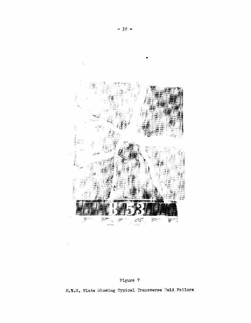
Figure 7
H.T~S. Plate Showing Typical Transverse ‘WeldFailure

— —.— — .—
\
F&are 8
FOR TFSTINGTHU S’rEELSPECI-
/MEW Ill A RYDMuLIC MEDIW