final report me 450: design and manufacturing iii fall 2006
TRANSCRIPT
Final Report
ME 450: Design and Manufacturing III
Fall 2006
Regenerative Braking for a Hydraulic Bicycle
Team 05
Bryan Kobie Andrew McCulloch Thomas Waisanen
Section Instructor Professor Alan Wineman
2
EXECUTIVE SUMMARY The Environmental Protections Agency (EPA) has been working with the University of Michigan to create a hydraulic regenerative braking system for a bicycle. The goal of the regenerative hydraulic braking project is to reduce the amount of energy required from the rider to accelerate the bike. When the rider engages the regeneration cycle for deceleration, a hydraulic motor stores energy from braking in the form of pressurized hydraulic fluid in an accumulating tank. When the rider wants to accelerate again, he/she runs the launch cycle, which uses the same motor to release the pressure in the tank and convert the stored energy into torque on the front wheel of the bicycle. Ideally, the pressure stored in the tank will provide enough energy to return the bike to its original speed prior to the regeneration cycle. This semester, our goal was to improve upon this system with the assistance of David Swain from the EPA. Previous ME450 teams have worked to build a working prototype; our task was to optimize the design by maintaining efficiency, by reducing the weight of the system, and by having it fit inside a standard bicycle front fork. We also improved the overall safety of the system to make it more user-friendly. We hope the product of our work demonstrated the benefits of hydraulic regenerative braking and the possibility of implementing this technology on other vehicles. Due to unforeseen circumstances, we had to reduce the scope of our project and focus only on the inner workings of the system, leaving the work of packaging the design to a future team. The prototype we designed is built and complete, and the next team can design around it. The customer requirements we can test for have been met but requirements such as system efficiency cannot be tested until a complete system is made.
3
TABLE OF CONTENTS Introduction…………………………………………………………………..…………… 4 Customer Requirements and Engineering Specifications……………………………… 4 Concept Generation and Selection..…….....…………………………………………….. 5 Engineering Design Parameter Analysis…..……………………………………………. 9 Final Design Description ………………………………………….……………………… 11 Prototype Description…….……………………………………….……………………… 14 Manufacturing Plan………………………………………………………………………. 15 Testing…………….………………......…………………………………………………… 16 Engineering Change Notices……………………………………..………………………. 16 Discussion…………………………………………………………………………………. 17 Recommendations……………………………….………………………………………... 19 Conclusions…...…………………………………………………………………………… 20 Acknowledgements….……………………………………………………………………. 21 Information Sources……………....……………………………………………………… 21 References …………………………………...……………………………………………. 22 Appendices …………………………………………………...…………………………… 23
4
INTRODUCTION Regenerative braking is a technology that stores energy from decelerating a body and makes that energy available for reuse. With traditional friction brakes, the kinetic energy of a body is 100% wasted as heat dissipated to surroundings. Regenerative braking has two common forms: hydraulic and electric. Electric systems use generators to convert kinetic energy into chemical potential energy via batteries. Hydraulic systems use pumps to convert kinetic energy into mechanical potential energy by pressurizing an incompressible fluid. The driving motivation for regenerative braking is increased efficiency for automobiles, which in turn would reduce greenhouse gas emissions and decrease dependence on fossil fuels. The United States Environmental Protection Agency (EPA) is developing hydraulic regenerative braking (HRB) systems for large sport utility vehicles and delivery trucks. Ford Motor Company has introduced a concept vehicle with Hydraulic Launch Assist (a type of HRB system) and claims that it is 80% energy efficient. On this wider basis, our project is beneficial because it casts HRB into a different field with unique requirements: low weight and small components. The hope is that anything learned by building HRB for a bicycle may be used to improve other HRB systems. Over the last few years, the EPA has sponsored a project at the University of Michigan that seeks to use HRB on a bicycle. Teams of undergraduate engineers have developed 3 generations of an HRB system, with each generation improving upon its predecessor. The first generation proved that an HRB system could function with a bicycle, but it was very heavy, unreliable, and overwhelmed the bicycle frame. The second generation improved the first by fitting more components inside a front wheel hub and by lightening the components. However, other components were still mounted to the bicycle frame and the design was still too heavy to use. The latest generation fit all of the components into the front wheel and improved the design of the front hub while reducing weight, but the size of the hub required a specialized fork to hold it. Our design, the fourth generation, can fit inside a standard bike fork and weighs much less than previous designs. With the guidance of David Swain and the EPA, we have improved upon the third generation of an HRB system for a bicycle. Our task was to optimize the design by maintaining efficiency, reducing the weight of the system, and having it fit inside a standard bicycle front fork. Due to unforeseen circumstances, our project goal changed mid-semester from focusing on the entire system to concentrating solely on the functional aspects of the internal mechanisms. We hope that our project can demonstrate the benefits of hydraulic regenerative braking and highlight the possibility of widespread implementation for this technology. CUSTOMER REQUIREMENTS AND ENGINEERING SPECIFICATIONS Customer Requirements for our project can be seen in the form of a Quality Function Deployment (QFD) diagram in Appendix A on page 23. Combining these customer requirements with our sponsor requirements, we derived the set of engineering specifications given below in Table 1. The size requirements were chosen so that the system can fit into most
5
standard bike forks without any complex adapters. Ideally, it would be possible to retrofit any bike with the hydraulic regeneration brake. Next, the braking and launch torque values were chosen such that the rider feels comfortable both stopping and accelerating. Earlier ME450 teams found that a braking torque of 130 N-m was enough to quickly stop the bike without coming close to flipping the bike over the front wheel. A launch torque of 90 N-m ensures that the front tire will not slip during launch, which keeps efficiency high. Finally, we hoped to improve the performance of the brake by reducing its weight to less than 50% of its predecessor and by increasing the maximum working pressure of the system. A higher pressure increases energy density of the operating fluid, which allows the system to either store more energy or be more compact. In general, the customer would like the system to outperform earlier prototypes while still being safe and efficient. Another important aspect of the design is ergonomics. Earlier models lacked in this area because the design teams were more concerned with developing a working system. Now that the general system has been developed, our team can concentrate on making the system user friendly. For instance, the customer needs an easy way to activate the system without removing their hands from the bicycle. Also, information about the pressure stored in the tank must be readily available so the rider can monitor system performance. Hopefully this and the improved ergonomics will make our design easier for users to adjust to the system, decreasing the learning curve. We want the customer to be comfortable using the brake in about an hour.
Table 1: Engineering Specifications and Target Values Engineering Specifications Target Value
Hub Width and Diameter 4” and 29”, respectively Maximum Braking Torque 130 N-m Top Speed ~25 mph Approximate Efficiency >70% Maximum Launch Torque 90 N-m
Maximum System Working Pressure 5000 psi Total Front Hub Weight <50 lbs
Learning Curve ~ 1 hour CONCEPT GENERATION AND SELECTION Our three main goals for this project were to reduce the weight of the system by half, to allow for the system to fit inside a standard 4” fork, and to have the system be universal for all bicycles. In choosing a design, we also kept in mind that a standard bicycle rim cannot withstand the high torques developed by the hydraulic system. Thus, we came up with several different concepts for strengthening the rim, lightening the components, and packaging everything together. The different parts of a HRB system that can be modified are: the two accumulators (high and low pressure), the pump and motor, the drive train, and the support structure (rim and

6
superbracket). The term superbracket refers to a solid plate inside the wheel that all the inner components mount to. These are the parts that we redesigned to meet the project goals. Reducing the Rim Weight The first idea for lightening the rim came about while observing last year’s design. The Fall 2005 team had taken a large block of aluminum and machined it down to a bike rim. While this was a strong design, it was much heavier than necessary and the aluminum itself was very costly. Since one of our main project goals is to reduce the weight of the system, we developed ideas to lighten the rim while keeping it strong. An idea presented to us by our sponsor was to create two half-shell hubs that, when connected, would create an entirely enclosed rim able to fit a 29” tire. The idea required two blocks of solid material, either aluminum or magnesium. Once we had these pieces, which would cost $1600 approximately, the machining would need to be outsourced because of complexity. The pros of this approach are weight reduction and fewer components in the final design. However, our group decided that the cost and turn-around-time for outsourcing was too great to continue on with this concept. The idea we are most hopeful about is to create six aluminum sections that will be attached to the inside of an existing rim. Each piece will cover four spoke holes and have the same angle of curvature as the 29” rim as seen in Figure 1. These segments would attach through the existing spoke holes with bolts and to the outer rim with welds. The sections will be attached to a carbon fiber hub that is designed to form a true circle.
Figure 1: One of six arc segments which attach to and reinforce rim
The main drawback of this design is complexity. Very precise manufacturing is required to ensure that a true wheel is formed when all the pieces come together. A wheel that is not true will cause vibration and negative handling effects. We had planned on manufacturing the wheel in such a way that roundness will not be an issue, but due to unforeseen circumstances we were unable to pursue this rim design. We hope that future teams will consider our concept.

7
Low Pressure Accumulator Design For the low pressure accumulator, previous groups used either a heavy piston-cylinder or made one out of metal. As the low pressure accumulator does not experience any pressures higher than atmospheric, these versions were both overbuilt. As such, we developed two concepts to reduce the weight of the accumulator: one with carbon fiber construction and one using a household plastic bottle. Carbon fiber construction allows the accumulator to be extremely light and made into any shape. However, at the time of our project there was an extreme shortage of carbon fiber and we could not find any within our budget. Carbon fiber is also expensive and requires a special mould material, which drives up project cost. Thus, we chose to reuse a plastic container for the accumulator. We found out what types of plastic are compatible with our water/glycerin hydraulic fluid and searched for a bottle that would fit inside our design. Any clear bottle made from the right material would have worked; for example, we considered bottles for soda, syrup, shampoo, soap, cooking oil, and condiments. It was also desireable for the bottle to have a large mouth, as we knew we would need to have two ports going through the cap. As such, we decided to use a large-mouthed, oval-shaped honey bottle. Accumulator Placement To improve handling, we initially decided to take the high and low pressure accumulators out of the front wheel. We considered mounting the accumulators on the bicycle frame or on a platform above the rear wheel. The major problem with external placement was that it prevented the bicycle from being a universal design. We ultimately decided to keep the accumulators inside the front hub in order to maintain the design’s versatility. With the placement known, we needed to decide how the accumulators would sit inside the wheel. The Fall 2005 semester placed the low pressure accumulator at an angle so when braking was initiated it would facilitate the accumulation of energy. Since handling is very important to our customer, we tried to place the accumulators as close to the axis of movement as possible. In this respect, the ideal placement for the accumulators is in line with the front forks to minimize inertial effects. The axle makes inline positioning impossible, and space is needed between the accumulators to accommodate plumbing. Thus, we decided to place the accumulators parallel to the forks with a large enough offset from the axle to make room for hosing. This configuration can be seen in Figure 2 on the next page.

8
Figure 2: Accumulators designed to be in-line with forks and offset from axle
Gear Selection After calculating gear ratios to stop and launch the bike (Appendix D), we searched for gears online that fit our packaging constraints. For the main drive gear, there were several types and configurations that would meet the torque and packaging constraints of the system. We considered three main systems: a planetary gear with inner spur gears, a standard gear-train with external tooth interfaces, and bevel gears. Planetary gears would require expensive, specialized parts and would also be difficult for us to manufacture and mount inside the wheel; thus, we chose to implement a standard gear-train. A standard gear train is more common and readily available, but it requires the motor and pump to be mounted laterally inside the wheel which makes the system wider than the required 4”. Finally, a set of bevel gears used in tandem with the standard spur gear train allows the motor and pump to be situated longitudinally, reducing their width impact. The bevel gears increase flexibility in gear ratios by adding an interface where gear ratios can be modified. For these reasons, we chose to use a standard spur gear set with a set of bevel gears, as shown in Figure 3.
Figure 3: Gear-train with large spur gear, small pinion gears, and bevel/miter gears

9
ENGINEERING DESIGN PARAMETER ANALYSIS The different components that required detailed engineering calculations were the gear train, the support structure or superbracket, and the axle. All calculations were made to optimize performance under load while minimizing weight. The main forces involved were torques in the gears and axle, and moments in the superbracket. We started with the gears and proceeded to the superbracket and axle. Finally, parameter analysis was performed for the hydraulic fluid. Gear Ratio Calculations The torque in the gear train is a direct response to the accelerations that the system provides. We wanted the system to stop a bike faster than it launched the bike for safety reasons. Thus, we designed the gear train around the braking cycle because that is when it experiences the highest torques. A previous team determined 3.63 m/s2 to be a comfortable deceleration, so we designed the system to generate a peak braking torque of 3.63 m/s2. Using the calculations in Appendix D on page 26, we determined the final gear ratio to be 18:1 between the pump shaft and the final drive gear. Thus, if the rider is traveling at 20 MPH and initiates braking, the bike tire is rotating at 232 RPM and the pump shaft is rotating at 4176 RPM. At 4176 RPM and 3000 psi system pressure, the pump is generating 4.52 N-m of torque. The gear train multiplies this torque to 81.36 N-m which decelerates the bike at 2.10 m/s2. The system pressure increases as braking continues and at 10 MPH the bike is decelerating at 2.93 m/s2. Similarly, at 5 MPH the bike is decelerating at 3.63 m/s2. Braking is ended at a little less than 5 MPH per operating instructions. We set the launch gear ratio to be 14.5:1 between the motor shaft and the final drive gear. The chosen gear ratio maximizes motor efficiency during launch as illustrated in Appendix C on page 22. The lower gear ratio also provides a gentler acceleration that is easy to control. At the maximum operating pressure of 5000 psi, the motor outputs 7 N-m of torque at 800 RPM (a little under 5 MPH bike speed). The bike is accelerated forward at 2.75 m/s2 initially and acceleration decreases as system pressure falls. We feel that the acceleration meets our requirements of being exciting as well as safe. Torque requirements for gear train Torque transfer through the gear train is directly related to the gear ratios that we selected. In our design, the pump gear train used a 2:1 gear ratio bevel set and a 9:1 gear ratio spur set to achieve the 18:1 final gear ratio. Similarly, the motor gear train used a 1:1 gear ratio bevel set and a 14.5:1 gear ratio spur set to achieve the 14.5:1 final gear ratio. The intermediate gear ratios determine the torque that each intermediate component transmitted. Using the simple gear relations listed in Appendix E, we determined the maximum torque requirements for each gear component. The torque values are listed in Table 2. Each gear must be rated with a service factor for its respective load to avoid failure during operation. The service factor of a gear is the rated torque value (usually found in a catalog) divided by the

10
operating torque (designed). Service factors normally range from 0.8 to 1.5 for gear applications, where lower values are appropriate for light use with little system shock. We set our service factor to 0.8 because the system is designed for very light use and none of the components cause shocks in the gear train. Ultimately, the lower service factor leads to lighter components which are important to our design. Table 2: Operating torques and necessary torque ratings in individual gears Pump Gear Train Motor Gear Train
Gear Operating
Torque (N-m)
Required Torque Rating (N-m)
Operating Torque (N-m)
Required Torque Rating (N-m)
1st bevel gear 4.52 3.62 7.57 6.06 2nd bevel gear 9.04 7.23 7.57 6.06 Pinion gear 9.04 7.23 7.57 6.06 Spur gear 81.36 65.09 110. 87.8 Design Requirements for Superbracket The superbracket is the plate of metal that everything is mounted on; we designed our it such that it met the strength and torque requirements while still being as lightweight as possible. Essentially, we wanted to remove as much material as possible from the stock plate while maintaining structural integrity. Our initial superbracket design was in the shape of a rectangle with the corners removed, as is shown in Figure 4 below. This allowed us to remove material while still being able to mount all the necessary components. In order to predict the bending moments and torques that were applied to it, we performed the strength calculations provided in Appendices H and I on pages 27-30. The superbracket needed to be thick enough that components can be bolted onto it, rigid enough that the pump and motor torques would not flex the plate, and strong enough that the axle plate bolts could absorb the main drive gear’s torque. We had planned to remove more material from the superbracket, but we were limited by the time constraints of the project.
Figure 4: Superbracket with mounting holes

11
Liquid Characteristics for Operating Fluid Hydraulic fluids vary in four main properties that effect how they work with equipment: viscosity, compressibility, lubricity, and compatibility. Viscosity is a fluid’s resistance to flow; compressibility describes how a fluid’s density changes under pressure; lubricity is the ability of a fluid to lubricate working parts; and compatibility describes the materials that may be used with a fluid. All of the properties can be designed to increase various parameters such as power transfer, efficiency, and durability. Even though last years project had notable efficiency it could be improved by changing the hydraulic fluid. The previous group found that the bicycle had the best performance at high ambient temperatures, which reduces fluid viscosity. To confirm this, we called the pump supplier and found out what fluid they used and at what temperature they tested the pumps. Using this information we were able to find the viscosity we needed. After some research, we chose to use an aqueous-glycerin solution because it may be easily tailored by varying the water content in the mixture. Most importantly, viscosity can be modified to the most efficient level for our intended operating conditions. The optimum viscosity for our design is 37 cSt, which is obtained with a mixture of 3:1 weight ratio of glycerin to water. The compressibility of the mixture is low enough that we are not worried about a change in performance under high pressure. Furthermore, lubricity may be varied by using chemical additives that will negligibly affect other fluid properties. Finally, glycerin is compatible with all of the hydraulic components previously described in the report because those components are intended for use with more caustic fluids. The only component that we had to design specifically for use with glycerin was the low pressure accumulator since we are building it ourselves. We found that PETE plastic, a common plastic used in soda bottles, is recommended for use with glycerin. FINAL DESIGN DESCRIPTION The final design incorporates three main systems: gears, hydraulics, and support. The gears are responsible for transferring force from the bicycle tire to the hydraulic system, thus enabling braking and launching. The hydraulic system stores energy during braking and delivers it during launch, and the support system remains stationary and fixes all components relative to each other. Figure 3, enlarged in Appendix F on page 28, shows the relationships between the three systems. The final design strikes a balance between efficiency, weight, and performance by tuning each system as described below.
12
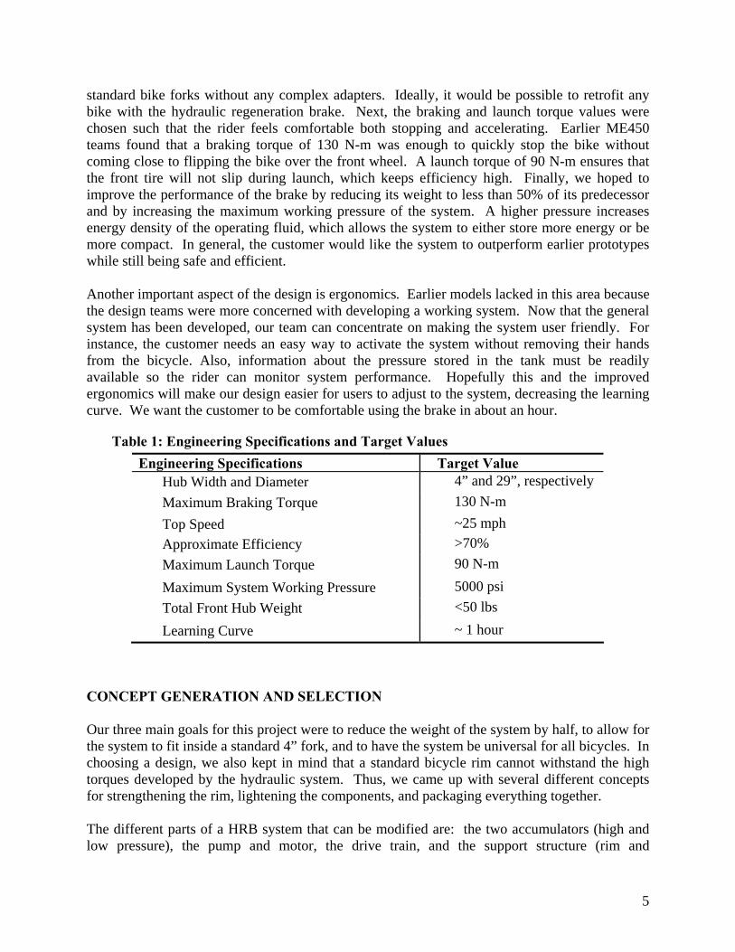
Figure 3: Final Component Layout
Gears The gears selected for our final design met the required torque ratings described in Table 2 on page 8. In addition to torque ratings, we used sizing and weight constraints to make our selection. Once assembled, the gear trains had an overall diameter less than 17 inches, and an overall thickness less than 3 inches. The approximate weight of the entire gear train will be 10 pounds without the large drive gear. Each gear train consists of a bevel gear set and a spur gear set. The pump bevel gears were in a ratio of 2:1 while the motor bevel gears were 1:1. The spur gear set amplifies and transmits torque to the main drive gear, which is rigidly attached to the bicycle wheel. The selected gearing allows the pump and motor to be mounted longitudinally, minimizing the width that each one requires. Each train is designed to deliver comfortable and efficient operating torques as detailed in the Engineering Design Parameter Analysis. Hydraulic Components In choosing our hydraulic components we wanted to ensure that each part was lighter than the previous years and would take up as little space as possible. In some cases where we were not given many options we looked at efficiency losses to make the best choice. Our sponsor took the first step towards improving last years bicycle by purchasing better components over the summer. In our first meeting, he provided us with an ACP Parker Hydraulic Accumulator and two Parker HY-09 Series Pump Motors. These parts helped greatly in minimizing the weight and size of the system. The pump and motor we used were 1.48 cc and can produce up to 7.83 N-m. Since they were significantly smaller than the previous semester’s, it allowed us to change their placement and put them parallel to the superbracket instead of perpendicular to it, thus saving space. The main improvement over last year’s high pressure accumulator was weight. Although our accumulator was longer than the previous year’s and would not be able to fit inside the previous 24” bicycle rim, the prospect of using a 29” rim allowed us to continue as planned and take
High Pressure Accumulator
Low Pressure Accumulator
Pump
Check Valve
Motor
3-Way Valves
Superbracket
13
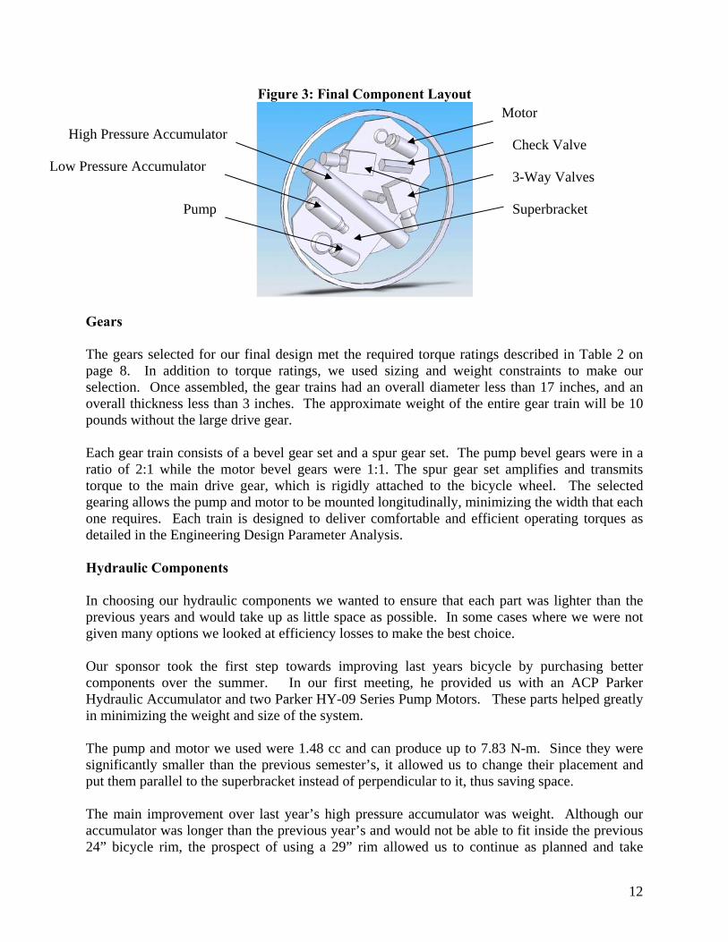
advantage of the benefits of the newer accumulator. This accumulator was also precharged to a higher pressure to improve energy density which allowed us to reduce the volume of operating fluid. The only thing we needed to do was decide how to fix the accumulator to our superbracket. We wanted to use clamps, which would make it easier to remove the accumulator from the system, but due to their size we decided to go with padded hose clamps which were smaller and lighter. One of the components which proved difficult to procure were the hydraulic valves. The project design calls for two high-pressure, three-way valves and a check valve. Our high pressure valves needed to be initially closed and then opened when charged. Initially we intended to use the same Parker valve model as the previous term because it met all the required specifications while being compact. After experiencing a lot of difficulty in getting these parts, we decided to look for a different valve producer. In our search, we found that Delta valves met our requirements in terms of leakage and flow. The one major downfall was that they were much larger and had different size hose fittings, although neither of these compromised the functionality of our design. Another component we hope to improve upon is the low pressure accumulator. Past semesters have used large, heavy, opaque containers, but we plan to use a simple plastic bottle with an aluminum cap. The bottle we have selected is extremely light, the proper volume, transparent, and quite cost effective. It is made of the plastic PETE, which is “recommended” as resistant to our hydraulic fluid. The aluminum cap threaded onto the bottle to provide a seal, and an SAE6 hole was drilled into the top of this cap to accommodate a hose fitting. Another hole in the cap was drilled to provide space for a breather tube which evacuates air from the bottle. The low pressure assembly can be seen below in Figure 6.
Figure 6: Low Pressure Accumulator with Adapter
Hydraulic Fluid In addition to the solid hydraulic components, the operating fluid of the hydraulic system was open to design. There are four different properties that must be considered when choosing a hydraulic fluid: viscosity, compressibility, lubricity, and compatibility. The pump and motor in our design were designed for a range of fluid properties, but their efficiency can be tuned. We

14
chose a 3:1 weight ratio of glycerine to water with a Propanol additive to meet our requirements as described in the Engineering Parameter Analysis section. Superbracket We originally designed our superbracket in the tentative shape of a rectangle as seen in Figure 4 on page 10, but more material was removed from the corners in order to reduce weight. After performing the bending moment calculations as shown in Appendix H, we decided that an aluminum plate with a thickness of 3/8” was appropriate. The shape resulted from the outspread locations of the pump, the motor, and the mounting bolts for the high pressure accumulator. The main drive axle was welded onto the axle plate which was bolted onto the superbracket. Strength calculations for the bolts on the axle plate can be seen in Appendix I. PROTOTYPE DESCRIPTION For the most part, our prototype matched our final design very closely; our actual prototype can be seen in Figure 7 below. However, there were some small differences between the two due to problems procuring components. Ideally, we wanted to use valves produced by Parker, as these were smaller, lighter, and presumed to be more efficient. However, due to ordering timeframes and unreliable distributors, we settled with larger Delta valves that match the desired functionality. Also, we had hoped to use a gear train with a larger drive gear and 1:1 bevel gears in order to most efficiently use the space available inside the wheel. However, torque requirements and gear supplier limitations have forced us to have the large drive gear be custom-made as well as to have an altered ratio in the bevel gears for the pump.
Figure 7: Actual Prototype
15
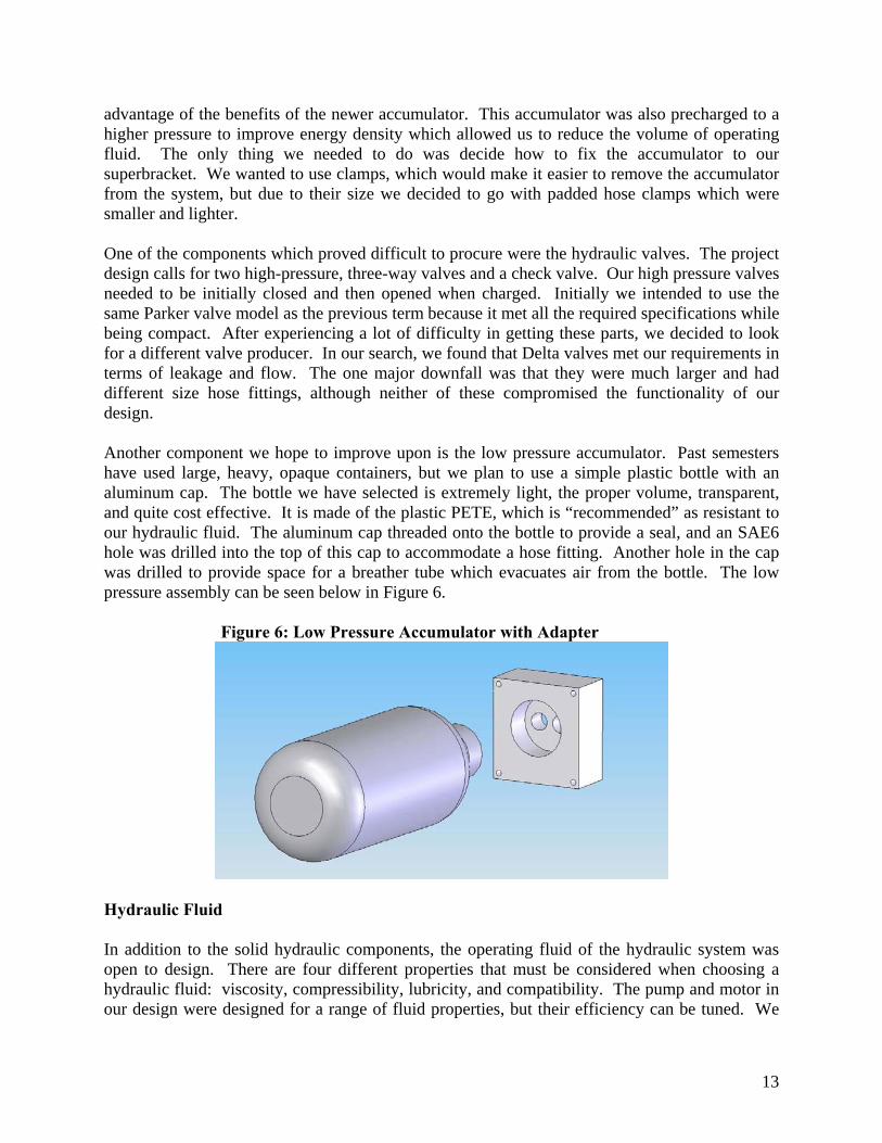
MANUFACTURING PLAN While much of our project is based on components that we have purchased, many components and fixtures needed to be manufactured. The following sections describe the design and manufacturing strategies for the superbracket, axle plate, the low pressure accumulator cap, and the pump mounting brackets. Superbracket The final design of the superbracket depended on the strength calculations and how much material we could remove. Our initial concept is shown in Figure 2 on page 9, but there is potential for more weight reduction. The stock material was originally a two foot square plate of 1/4” thick steel. Due to a warped piece of steel, we decided to change the material to aluminum and increase its thickness to 3/8”. In the first process, we drilled several different holes: the mounting holes for the accumulator hose clamp mounts, the pinion shaft holes, and the center axle hole. It was important to have this all done in the same machining session as it is critical that the shaft holes and axle holes be located exactly as designed. After mounting all the components, we then cut off as much excess material as possible with a bandsaw. We then tapped the bolt holes and welded the angle iron pump brackets in the proper location. Axle Plate The axle plate can be seen in Figure 8 below. After we designed the axle plate, we decided that it needed to be machined out of one piece of stock in order to have exact perpendicularity. As such, we purchased a single large block of mild steel sized at 5” x 5” x 1”. First, we faced off the sides and made the piece square with an end mill. Then, using a CNC mill, we programmed the dimensions of the part and let the mill run. After the boss and axle hole were milled out, we drilled out the six bolt through-holes as accurately as possible. To remove more material and lighten the part, we then mounted it in a lathe with the axle-hole boss clamped in the chuck; this allowed us to have a circular edge around the six bolt holes as opposed to a square edge. Finally, we welded the axle onto the axle plate on both the front and back of the part, making sure the axle was as perpendicular to the plate as possible.
Figure 8: Axle Plate with bolt holes and axle hole

16
Cap for Low Pressure Accumulator To modify a standard plastic bottle into a low pressure accumulator, we needed a cap that could seal the container and had holes for the fluid flow as well as a breather plug. Our final design for this cap can be seen in Figure 6 on page 13. The stock material was a block of aluminum, which we cut with a bandsaw to rough dimensions and then faced off the sides with an endmill. Then, without removing the block from the mill vise, we drilled the bolt holes as well as the through-holes for the hosing. Finally, we tapped the bolt holes. Pump and Motor Mounting Brackets To mount the pump and motor to the superbracket, we used simple aluminum angle iron with through-holes that match the pump and motor bolt holes. First we cut the angle iron to a reasonable length with a bandsaw, and then we drilled and tapped the bolt holes. After this we milled out a circular portion of the angle iron for the pump/motor shaft to pass through. These brackets are bolted onto the superbracket. TESTING The assembly of our prototype in itself was a test to see if we had met our goals. All the components, even the oversized valves, fit on the superbracket within the constraints of a 29” bicycle rim. The gearing fit together well and operated smoothly. Unfortunately, we were unable to test for our other design specifications because the packaging has not been designed yet, a project left for next term. Until this is done we cannot know the final weight or if it will fit inside a standard bicycle fork. To test the system for functionality it has to be charged. The ideal way to charge it would be to place it in a bicycle and engage the hydraulic braking. Again, this cannot be done until the packaging is designed. It is possible to charge the system without a bicycle but this requires designing a test stand and testing the regen and launch systems independently. ENGINEERING CHANGE NOTICES Although our prototype is a good representation of what we designed, there have been some minor changes. Superbracket Soon after we began manufacturing we realized that the steel plate we were going to use was bowed. Because of the close tolerances needed for the gear train it could not be used. After consulting different sources we learned that steel is much more likely to bow than aluminum. Through calculations we found that a 3/8” thick piece of aluminum would provide the same strength as the ¼” steel and therefore decided to sacrifice that 1/8” so that the system could

17
work. This decision in the end was very beneficial because the weight of the entire system was reduced dramatically. Low Pressure Accumulator Adaptor After manufacturing the low pressure accumulator adaptor we realized that a plate to hold the bottle in place was not needed. The bottle’s cap, which was epoxied into the aluminum adaptor, held the bottle firmly. This cut down on overall manufacturing time and did not affect any other part of the project. A picture of the initial design is shown below in Figure 9, the final design can be seen in Figure 6 on page 13.
Figure 9: Initial Low Pressure Accumulator Adaptor Design
DISCUSSION We feel that we accomplished an immense amount of work this semester, and we definitely view our project as an overall success. That being said, many components in the project could have been designed differently, optimized, or further improved upon. This section also considers more specifically where there is the most potential for weight and thickness reductions. Design Critique One of the components in our project that turned out the best was the superbracket. After calculating the amount of bending and flexing for both steel and aluminum, we discovered that we could lighten the part considerably by using aluminum. Additionally, the care we took to accurately machine the axle holes was critical to the perfect alignment of all components. The time we put into the superbracket paid off, and it is an excellent reflection of the thought and effort we put into the project. However, there are still areas that could be improved upon. For
18
example, much more material could be removed from corners or where strength is less needed, and it might even be possible to use a thinner plate to reduce the overall thickness of the system. Another component that we view as a success is the low pressure accumulator. We definitely put thought into weight savings and practicality, and we think that there is very little refinement needed with our current design. It is light and efficient, and is one of the few places where we were really able to be creative with the project. The aluminum cap could be lighter, but the time needed for machining probably does not warrant the weight saving possibilities. The axle plate was well designed, but we could have better thought out the manufacturing plan. We calculated the number and size of the bolts needed to withstand the applied torque, and we also calculated the necessary wall thickness. However, we should have realized that removing material from steel takes significant time. Instead of machining the entire axle plate (with the protruded boss) from one large block of steel, we should have welded a pre-made cylindrical block to a pre-made plate. Then, we could have still drilled out the axle and bolt holes at the exact locations without needing to remove all the excess material around the boss. There are many other less-significant components that turned out well, yet still have room for improvement. For example, the valves we ordered serve their purpose, but were not the original valves we wanted and were much heavier than necessary. Also, the main drive gear is perfectly sized and meshes well with the entire gear train, but we did not have enough time to remove material and lighten it. A third example is the bearing and standoff systems for both pinion gears; while everything meshes and rotates freely, there are several places where clearances and heights can be reduced to lessen the overall thickness. A fourth example is the hosing, where we simply connected everything as needed without optimizing the junctions or minimizing the lengths. Potential for Weight and Thickness Reductions The most critical component to improve is the main drive gear. Weighing 35 lbs, it could be spoked and thinned out to remove as much as 75% of its weight. Additionally, in the final design, the gear will be rigidly attached to the wheel and will not need to be in contact with the axle, so even more material will be able to be removed from its center. The valves are the next most critical components for weight reduction. Unless a better, high pressure 3-way solenoid valve can be found, we recommend replacing our 10 lb Delta valves with 1.4 lb Parker valves. There are several more components that can be adjusted or improved upon to reduce thickness or lighten the system, and these can be seen in Table 3 on page 19.
19
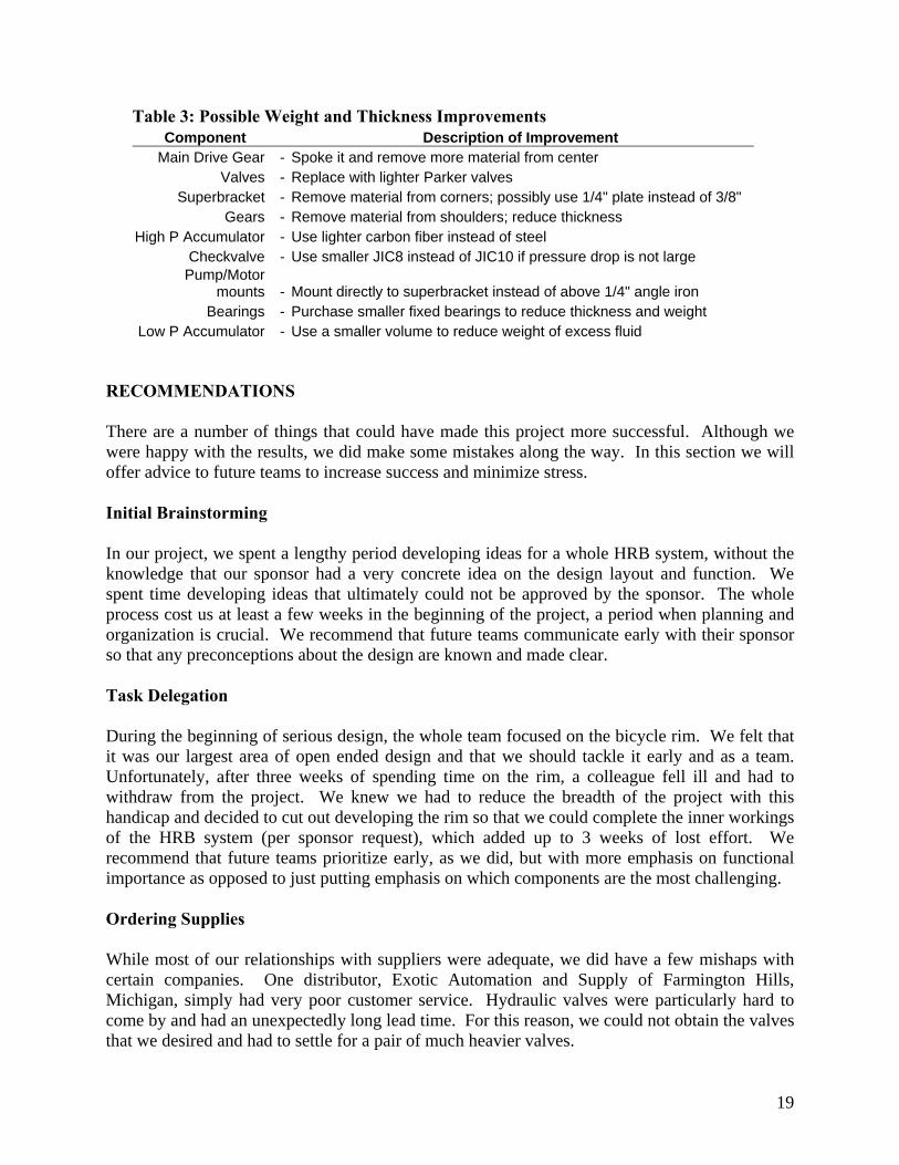
Table 3: Possible Weight and Thickness Improvements Component Description of Improvement
Main Drive Gear - Spoke it and remove more material from center Valves - Replace with lighter Parker valves
Superbracket - Remove material from corners; possibly use 1/4" plate instead of 3/8" Gears - Remove material from shoulders; reduce thickness
High P Accumulator - Use lighter carbon fiber instead of steel Checkvalve - Use smaller JIC8 instead of JIC10 if pressure drop is not large
Pump/Motor mounts - Mount directly to superbracket instead of above 1/4" angle iron
Bearings - Purchase smaller fixed bearings to reduce thickness and weight Low P Accumulator - Use a smaller volume to reduce weight of excess fluid
RECOMMENDATIONS There are a number of things that could have made this project more successful. Although we were happy with the results, we did make some mistakes along the way. In this section we will offer advice to future teams to increase success and minimize stress. Initial Brainstorming In our project, we spent a lengthy period developing ideas for a whole HRB system, without the knowledge that our sponsor had a very concrete idea on the design layout and function. We spent time developing ideas that ultimately could not be approved by the sponsor. The whole process cost us at least a few weeks in the beginning of the project, a period when planning and organization is crucial. We recommend that future teams communicate early with their sponsor so that any preconceptions about the design are known and made clear. Task Delegation During the beginning of serious design, the whole team focused on the bicycle rim. We felt that it was our largest area of open ended design and that we should tackle it early and as a team. Unfortunately, after three weeks of spending time on the rim, a colleague fell ill and had to withdraw from the project. We knew we had to reduce the breadth of the project with this handicap and decided to cut out developing the rim so that we could complete the inner workings of the HRB system (per sponsor request), which added up to 3 weeks of lost effort. We recommend that future teams prioritize early, as we did, but with more emphasis on functional importance as opposed to just putting emphasis on which components are the most challenging. Ordering Supplies While most of our relationships with suppliers were adequate, we did have a few mishaps with certain companies. One distributor, Exotic Automation and Supply of Farmington Hills, Michigan, simply had very poor customer service. Hydraulic valves were particularly hard to come by and had an unexpectedly long lead time. For this reason, we could not obtain the valves that we desired and had to settle for a pair of much heavier valves.

20
There are other things to look out for besides lead times and poor service. It is very important that teams make sure an invoice for ordered parts is available. A majority of our shipments arrived with no invoice attached and we had to request an invoice separately. Most of the suppliers were very helpful in getting invoices and they did not cause any frustration. We also recommend that future teams maintain vigil on shipments and get updates from distributors very often. Machining Our machine process was successful despite starting later than planned. However, there were added frustrations and long work days because of the late start, which resulted from miscommunication with the machine shop. To compound the problem, it often takes longer than planned to machine a part. For these reasons, we recommend that future teams plan more than adequate time for machining, talk with professors about machine shop dates, and, if possible, look for secondary places to machine to ensure that parts get made when intended. Prototype Assembly On this project in particular, prototype assembly is very involved and time consuming. The plumbing of the hydraulics requires a lot of mental effort to ensure that all clearances are met while maintaining high efficiency by eliminating sharp changes in flow direction. We recommend that future teams perform the assembly at the EPA where many parts and experienced people can be found. CONCLUSIONS As a continuation of previous projects, our project goal was to improve the most recent design of a hydraulic regenerative braking system for a bicycle. The most recent design was too large for use with a standard bike fork, and its weight impeded steering and made the bicycle cumbersome. In order to make the system more attractive to potential users, the weight needed to be reduced greatly and the dimensions needed to change so that installation on any common bicycle could be possible. In addition to these goals, our design needed to maintain high efficiency established by the earlier design, and provide safety mechanisms in the design to protect the user. In response to the design problem, we developed a set of specifications and designed a prototype to meet the specifications. We accomplished the project goals by using lighter components and by redesigning the layout of the components to save space. The major components that accounted for weight savings were the accumulators, the superbracket, and the pump and motor. Unfortunately, we could not finish the complete prototype and install it on a bicycle because of unforeseen circumstances. However, the prototype that was created meets all of the specifications that can be measured without a complete bike; it fits inside a standard bicycle fork, weighs considerably less than previous designs, and implements safety devices. We believe that
21
our system will deliver the intended braking and launch forces and maintain high efficiency once it is coupled with a hub designed by a future team. While we believe our prototype is a very successful solution to the original engineering problem, there are still a few things that can be improved to optimize the design. Most importantly, the existing 3-way valves should be replaced with the lighter versions that the design originally called for. Next, the superbracket could be reworked with more detailed stress and deflection calculations to see where excess material can be machined away. Finally, the main gear that we received for the prototype is made of solid steel. It is intended that the team responsible for creating a wheel hub will machine the gear to whatever shape they need and then remove excess material. If all of these things are done, a great weight savings will be accomplished and our prototype will be even more successful. ACKNOWLEDGEMENTS First and foremost we would like to thank the United States Government’s Environmental Protection Agency (EPA) and our sponsor David Swain. The grant provided to the University of Michigan by the EPA has allowed us to take part in this exciting project which has certainly enhanced our educational experience at this University. We are also thankful to Bob Coury and Marv Cressey for their machining advice and to Steven Emanuel for putting in long hours to help us manufacture our prototype. Last, but not least we would like to thank Ann Arbor Gearing Technologies for donating a large custom made gear essential to the completion of our final design. INFORMATION SOURCES Since our project is a continuation of the work from previous teams, we had the privilege of accessing their reports and documentation. As such, two of our main sources of information were Jason Moore, a graduate student who has worked on the project for over a year, and our sponsor from the EPA, David Swain, who has led this project for several semesters. In addition to the EPA and former students, we used the internet a great deal to research products and gather information. During gear development we procured catalogues online and used them to specify which gears we required. During fluid development, we performed research into various liquids and read scientific studies that applied to our specific application. We also used the internet to perform a patent search on HRB systems for bicycles. One version of an electrohydraulic/air bike has already been patented (Patent # 4942936) by Elmer W. Gardner, Jr. In his design, the working fluid – either hydraulic fluid or air – can be pressurized both by braking and by pedaling. The system is said to be functional, but the design overwhelms the frame of the bicycle as seen in Figure 9. The largest part of this system is a complex gear train comprising of screw gears, worm gears, and spur gears. In contrast, our design fits inside the front wheel.

22
Figure 9: Patent #4942936 is for a complex hybrid bicycle that employs hydraulic and electric power transfer.
REFERENCES 1. Fall ’05 Final Report: Regenerative Braking for a Hydraulic Bicycle
Kristin Ciarelli, Sean Cranford, Steven El Aile, Jason Moore 2. United States Patent and Trademark Office Home Page
http://www.uspto.gov/

23
APPENDIX A
QFD Diagram with customer requirements and engineering specifications

24
APPENDIX B Gantt Chart
25
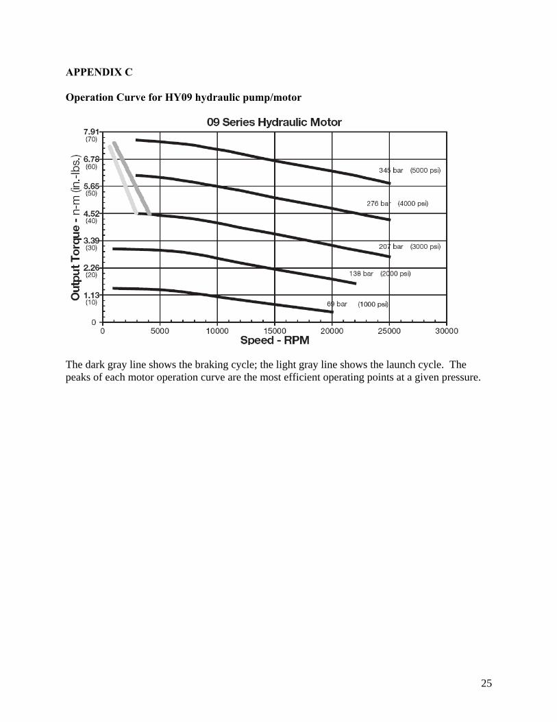
APPENDIX C Operation Curve for HY09 hydraulic pump/motor
The dark gray line shows the braking cycle; the light gray line shows the launch cycle. The peaks of each motor operation curve are the most efficient operating points at a given pressure.
26
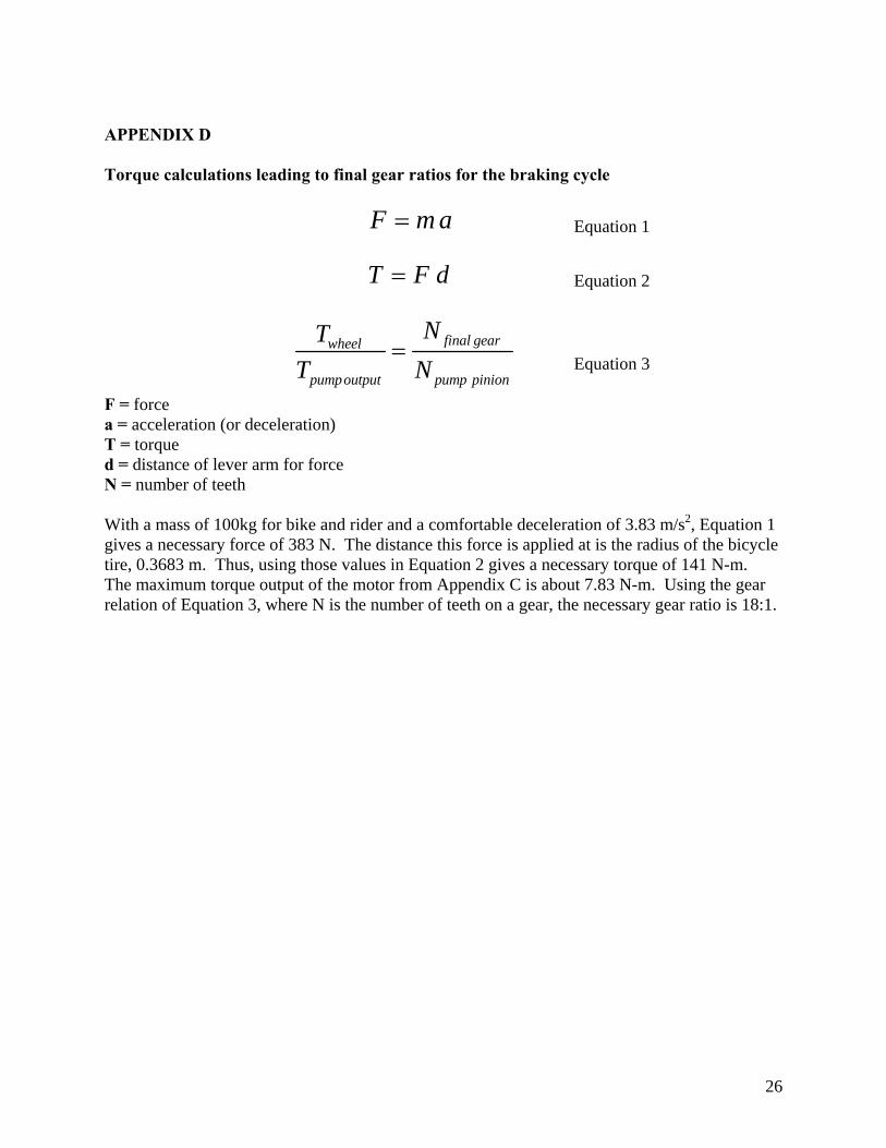
APPENDIX D Torque calculations leading to final gear ratios for the braking cycle
F m a= Equation 1
T F d= Equation 2
final gearwheel
pumpoutput pump pinion
NTT N
= Equation 3
F = force a = acceleration (or deceleration) T = torque d = distance of lever arm for force N = number of teeth With a mass of 100kg for bike and rider and a comfortable deceleration of 3.83 m/s2, Equation 1 gives a necessary force of 383 N. The distance this force is applied at is the radius of the bicycle tire, 0.3683 m. Thus, using those values in Equation 2 gives a necessary torque of 141 N-m. The maximum torque output of the motor from Appendix C is about 7.83 N-m. Using the gear relation of Equation 3, where N is the number of teeth on a gear, the necessary gear ratio is 18:1.
27
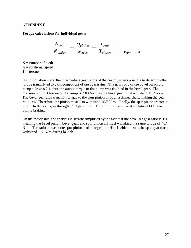
APPENDIX E Torque calculations for individual gears
gear pinion gear
pinion gear pinion
N TN T
ωω= =
Equation 4
N = number of teeth ω = rotational speed T = torque Using Equation 4 and the intermediate gear ratios of the design, it was possible to determine the torque transmitted to each component of the gear trains. The gear ratio of the bevel set on the pump side was 2:1, thus the output torque of the pump was doubled in the bevel gear. The maximum output torque of the pump is 7.83 N-m, so the bevel gear must withstand 15.7 N-m. The bevel gear then transmits torque to the spur pinion through a shared shaft, making the gear ratio 1:1. Therefore, the pinion must also withstand 15.7 N-m. Finally, the spur pinion transmits torque to the spur gear through a 9:1 gear ratio. Thus, the spur gear must withstand 141 N-m during braking. On the motor side, the analysis is greatly simplified by the fact that the bevel set gear ratio is 1:1, meaning the bevel pinion, bevel gear, and spur pinion all must withstand the same torque of 7.7 N-m. The ratio between the spur pinion and spur gear is 141/2:1 which means the spur gear must withstand 112 N-m during launch.

28
APPENDIX F Final Component Layout

29
APPENDIX G: Cost Analysis Sheet
Qua
ntity
Part
Des
crip
tion
Purc
hase
d Fr
omPa
rt N
umbe
rPr
ice(
Each
)Pr
ice(
Tota
l)U
se1
Gal
lon
Tech
nica
l Gra
de G
lyce
rinC
LP C
hem
ical
s*G
LY99
5TC
H00
1$1
10.2
9$1
10.2
9Fl
uid
150
0 m
L P
ropa
nol
Sci
ence
Stu
ff**
C24
29$4
1.83
$41.
83Fl
uid
13"
x 3"
Ang
le Ir
on (1
ft)
AS
AP
Sou
rce,
Ann
Arb
orN
/A$1
2.62
$12.
62A
ccum
ulat
or/E
ngin
e M
ount
s1
1' x
2' x
3/8
" Alu
min
umA
SA
P S
ourc
e, A
nn A
rbor
2800
7000
$101
.50
$101
.50
Sup
erbr
acke
t1
6" x
6" x
1.2
5" S
teel
Blo
ckA
SA
P S
ourc
e, A
nn A
rbor
AA
A00
300
$9.7
5$9
.75
Axl
e P
late
15/
8" D
iam
eter
Ste
el R
od (1
ft)
AS
AP
Sou
rce,
Ann
Arb
or13
8017
00$1
2.66
$12.
66R
egen
Gea
ring
Sha
ft2
Del
ta P
ower
Val
veFe
dera
l Flu
id P
ower
, Ply
mou
thH
U-S
3E-0
0-D
L-12
-S$1
53.6
3$3
07.2
6V
alve
s6
SA
E10
-JIC
6 Fi
tting
sFe
dera
l Flu
id P
ower
, Ply
mou
thA
3105
-6-1
0$1
.94
$11.
64Fi
tting
s fo
r Val
ves
1P
arke
r Hyd
raul
ic H
igh
P A
ccum
ulat
orE
xotic
Aut
omat
ion
AC
P05
AA
075E
1KTC
$141
.00
$141
.00
Hig
h P
ress
ure
Acc
umul
ator
2P
arke
r 09
Ser
ies
Hyd
raul
ic G
ear M
otor
sE
PA
09S
GC
KP
$0.0
0$0
.00
Reg
en/P
ump
Mot
ors
1B
osto
n S
pur G
ear (
.5" B
ore)
Mot
ion
Indu
strie
sN
B18
B-1
/2$1
9.10
$19.
101
Bos
ton
Spu
r Gea
r (5/
8" B
ore)
Mot
ion
Indu
strie
sN
B28
B-5
/8$2
8.20
$28.
201
Bos
ton
Bev
el G
ear (
5/8"
Bor
e)M
otio
n In
dust
ries
L152
BY-
G$5
2.20
$52.
201
Bos
ton
Bev
el G
ear (
.5" B
ore)
Mot
ion
Indu
strie
sL1
52B
Y-P
$32.
40$3
2.40
2B
osto
n M
iter G
ear
Mot
ion
Indu
strie
sH
LK10
1Y$2
8.20
$56.
401
Ste
el S
pur G
ear 1
6" P
itch/
252
teet
hA
nn A
rbor
Gea
ring
Tech
nolo
gies
N/A
$0.0
0$0
.00
Mai
n G
ear
1P
air o
f Jac
k S
tand
sW
alm
art
7003
0567
058
$17.
89$1
7.89
Des
ign
Exp
o D
ispl
ay1
29" B
icyc
le R
imW
heel
s in
Mot
ion,
Ann
Arb
or$5
7.24
$57.
24Fo
r use
by
next
term
1B
earin
g M
ount
(5/8
" Bor
e)M
cMas
ter-
Car
r***
5968
K72
$25.
91$2
5.91
Bea
ring
Mou
nt R
egen
1B
earin
g M
ount
(.5"
Bor
e)M
cMas
ter-
Car
r***
5968
K71
$25.
91$2
5.91
Bea
ring
Mou
nt P
ump
1S
tain
less
Ste
el K
ey S
tock
1/8
" x 1
/8" x
12"
McM
aste
r-C
arr*
**92
530
A10
0$2
.00
$2.0
0La
unch
Key
1S
tain
less
Ste
el K
ey S
tock
3/1
6" x
3/1
6" x
12"
McM
aste
r-C
arr*
**92
530
A11
7$3
.02
$3.0
2R
egen
Key
1S
teel
Bal
l Bea
ring
(5/8
" Bor
e)M
cMas
ter-
Car
r***
6035
5 K
47$6
.00
$6.0
0R
egen
Bea
ring
1S
teel
Bal
l Bea
ring
(.5" B
ore)
McM
aste
r-C
arr*
**60
355
K46
$4.9
6$4
.96
Laun
ch B
earin
g1
.5" D
iam
eter
Sha
ft (1
ft)
McM
aste
r-C
arr*
**92
530
A11
8$8
.95
$8.9
5P
ump
Sha
ft3
Hos
e B
arb
Tee
(3/8
")A
ce H
ardw
are,
Ann
Arb
or40
2973
2$5
.99
$17.
97Lo
w P
ress
ure
Hos
ing
11H
ose
Cla
mp
(Siz
e)A
ce H
ardw
are,
Ann
Arb
or41
915
$1.2
9$1
4.19
Low
Pre
ssur
e H
osin
g26
1/4-
20 B
olts
Ace
Har
dwar
e, A
nn A
rbor
*56
$0.0
8$2
.08
Ass
embl
y26
1/4-
20 N
uts
Ace
Har
dwar
e, A
nn A
rbor
*56
$0.2
0$5
.20
Ass
embl
y6
5/8"
Bol
tsA
ce H
ardw
are,
Ann
Arb
or*5
6$0
.35
$2.1
0A
ssem
bly
1C
oupl
e 3/
4"A
ce H
ardw
are,
Ann
Arb
or43
105
$0.1
9$0
.19
Spa
cer f
or M
ain
Gea
r1
8' T
ube
3/8
IDA
ce H
ardw
are,
Ann
Arb
or40
2750
4$3
.12
$3.1
2Lo
w P
ress
ure
Tubi
ng1
Mag
net C
eram
ic B
lock
Ace
Har
dwar
e, A
nn A
rbor
2108
553
$3.4
9$3
.49
Low
Pre
ssur
e A
ccum
ulat
or F
ilter
* w
ww
.clp
chem
ical
s.co
m**
ww
w.s
cien
cest
uff.c
omTo
tal
$1,1
37.0
7**
* w
ww
.mcm
aste
r.com
30
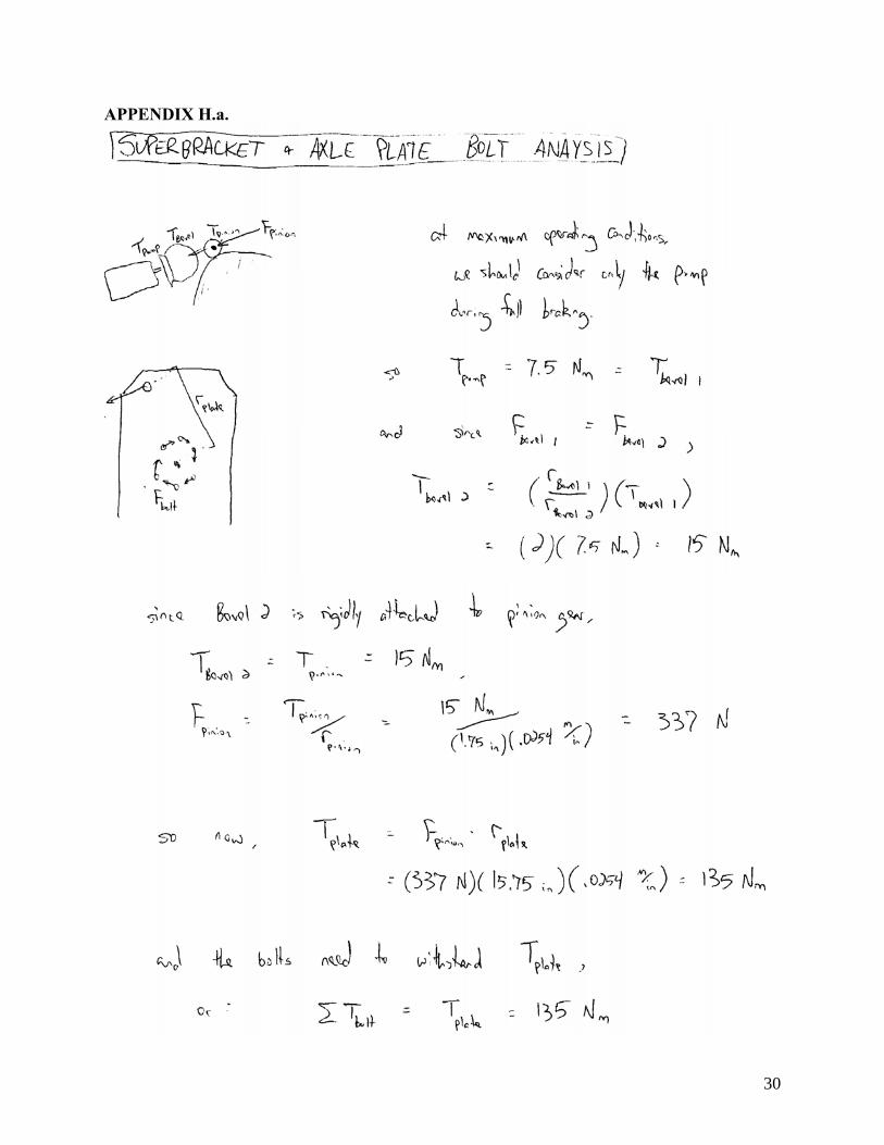
APPENDIX H.a.

31
APPENDIX H.b.

32
APPENDIX I.a.
33
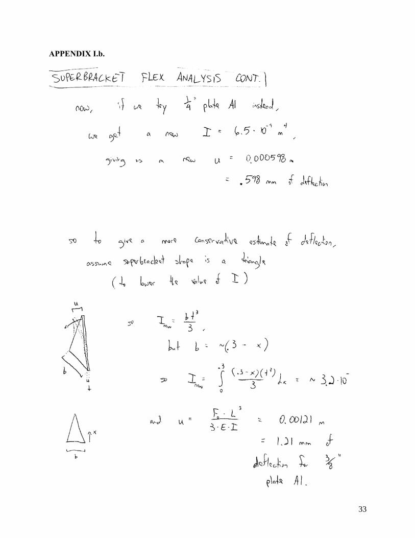
APPENDIX I.b.