me 450: design and manufacturing iii
TRANSCRIPT

ME 450: Design and Manufacturing III Final Report
Piston Alignment Fixture
Sponsored by: The Environmental Protection Agency
Presented by:
Team 8 Sabrina Hall David Lenss
Evan Quasney Kristina Tolbert
Section Instructor:
Dr. Kazuhiro Saitou
18 April 2006

EXECUTIVE SUMMARY 3
ABSTRACT 4
PROBLEM DESCRIPTION 4
INFORMATION SOURCES 5
CUSTOMER REQUIREMENTS 6
ENGINEERING REQUIREMENTS 7
QUALITATIVE FUNCTION DEPLOYMENT (QFD) MATRIX 9
CONCEPT GENERATION 9
CONCEPT SELECTION 12
THE ALPHA DESIGN 12
ENGINEERING DESIGN PARAMETER ANALYSIS 13
FINAL DESIGN DESCRIPTION 15
PROTOTYPE DESCRIPTION 18
DESIGN VALIDATION PLAN 18
MANUFATURING PLAN 19
PROJECT PLAN 22
PROBLEM ANALYSIS AND DISCUSSION 22
RECOMMENDATIONS 25
CONCLUSIONS 25
ACKNOWLEDGEMENTS 26

REFERENCES 26
BIOGRAPHIES 27 Appendix A: Example Bent Axis Pump Images Appendix B: Qualitative Function Deployment Matrix Appendix C: Gantt Chart Appendix D: Design Concepts Appendix E: Pugh Chart Appendix F: Alpha Prototype Razor Engineering Prints Appendix G: Engineering Prints for Final Design Appendix H: Bill of Materials Appendix I: Rapid Prototype Appendix J: Photographic Manufacturing Description Appendix K: Design Safe Analysis
- 2 -

EXECUTIVE SUMMARY The assembly of bent axis pumps is difficult due to high tolerances, tight spaces, and articulated subassemblies. The EPA requested the design and fabrication of a fixture that aligns and fits 9 pistons into bores and aligns a CV joint faster than their current process. The purpose of this document is to present a problem description, literature search, customer and engineering specifications, problem analysis, concept generation and selection, engineering design parameters, final design description, prototype description, final manufacturing plan, final validation plan, project plan, and a description of our design validation and recommendations. The bent axis pump used by the EPA is being tested to examine the wear experienced over a set of operating conditions. A test regimen to examine this wear calls for the rapid disassembly, inspection, and reassembly of the pump over short intervals of time. The current disassembly and assembly method requires two people, multiple hand tools, and a lot of grunt work. A fixture that reduces assembly time to less than 10 minutes will be designed and fabricated. Bent axis pumps are protected under US Patent 6,773,368. While the pump itself is described in great detail, no information is provided to characterize the assembly process. No assembly fixtures or procedures were found to provide benchmarking analysis. Qualitative requirements were defined based on input from the customer. The customer requirements are a faster assembly / disassembly time, a small size, able to maintain tolerances, easy to use, easy to remove, durable, low cost, safe, lightweight, and anticipates pump redesign. From these customer requirements, engineering specifications were developed, and their importance assessed using a Qualitative Function Deployment matrix. The selected final designs were the Piston Catcher and The Razor. These two tools were chosen due to space and geometry constraints. The Piston Catcher is sectioned into three pieces to allow assembly in the available space. A full-scale mock up of the fixture was prototyped using a ZCorp 310 RP machine, and made of plaster ZP102. A prototype of the Razor was not deemed necessary. The final design was made of Aluminum 6061 on a Milltronics Manufacturing CNC Mill with Centurion Mk I CAM controller, with standard metric ISO tolerances. The final manufacturing plan estimates that machining will take approximately 50 hours. A feasibility and validation test was conducted at the EPA to demonstrate that the engineering specifications of the final design had been fulfilled to determine the effectiveness of the final design. With practice, the EPA could possibly assemble the pump in 60 – 90 seconds, a 900% improvement over the current method. From this validation test, several recommendations were drawn up for minor changes to the final design to fully optimize the functionality of the fixture. The timeline of this project spanned a 15-week period, beginning January 10 and ending April 18. Four milestone design reviews must be completed, each with a written report and oral presentation. The project was completed with the budget of $400.
- 3 -

ABSTRACT The Environmental Protection Agency (EPA) is involved in research and design of high-efficiency hybrid vehicles based on hydraulic systems. Building and testing hydraulic piston pumps form part of this study. Nine pistons in a two-inch circle are spherically-jointed to connecting rods and surround a central constant velocity (CV) joint. The pistons and CV joint must be assembled simultaneously into a mating barrel inside the pump housing; the multiple joints make it difficult to align all parts at once. This project is to design a removable fixture to position the pistons and line up the CV joint for proper assembly within tight quarters. PROBLEM DESCRIPTION Problem Background The EPA is in charge of the certification of vehicles for public use. The EPA also does research and development in applications to reduce waste and pollution. One such application is in hybrid vehicles. To increase efficiency in hybrid vehicles the EPA is researching and developing hydraulic systems. Currently, they are building and testing bent axis hydraulic piston pumps. The EPA is conducting tests to examine wear on the back plate of their bent axis pumps. This requires that the pump be inspected frequently, during which time it must be completely disassembled for inspection, and reassembled again to resume testing. It is difficult to reassemble the pump due to space constraints and the geometry of the part. It typically takes two operators approximately 10 minutes to reassemble the 15lb pump. This project is to design and manufacture a device used to quickly and easily assemble the pistons and constant velocity (CV) joint. Bent Axis Pumps Background A bent axis pump has six main parts shown in Figure 1 (page 3) and Appendix A: a back plate, swash plate, yoke, nine pistons, CV joint, barrel, inlet passage, and outlet passage. The nine pistons are centered on a two inch diameter circle with 0.0005 inch clearance between each piston and its corresponding bore. These pistons surround a CV joint that holds the barrel and swash plate together and allows them to rotate while at different angles. The rotating plane (produced by the yoke angle) is at an angle to the plane of the back plate, putting each piston at a different depth within the barrel. The inlet passage fills the bores with hydraulic fluid when the pistons are away from the barrel, and the outlet passage is open to the bores when the pistons move toward the barrel. The output fluid is at a higher pressure than the input, which provides energy that is stored to be used by the vehicle. To assemble this pump, the pistons must first be lined up with the bores in a specific order. Each piston must go in a specific bore so that the CV joint will line up correctly. The top three pistons, when the pump in on a test bench in the zero degree position, are first manually put into their bores. Next two more pistons, one on each side of the first three, are put into their bores. This process is repeated until all pistons are in the barrel. While one person is inserting the pistons as described, a second person manipulates the yoke by changing its angle with respect to the horizontal and holding it closer or farther away from the swash plate. After all pistons are
- 4 -

inserted, one person reaches between the piston shafts with their fingers or small screwdrivers to connect the CV joint.
Figure 1: Bent Axis Pump
Project Outcome This project will design and manufacture two fixtures, one to align the 9 pistons with the barrel, and another to connect the CV joint. This will make the assembly of the pump quicker, easier, and safer than the current situation. This fixture will hopefully save the EPA a significant amount of time and frustration through the course of their testing process. INFORMATION SOURCES The invention of bent axis pumps, also called variable axis hydraulic pumps, is credited to Geoffrey Allan Williames in Victoria, Australia. Bent axis pumps are protected under US patent 6,773,368 as of January 21, 2001. The patent does not provide any discussion of an assembly or alignment method for the pistons with their respective bores. The method of alignment between the CV joint, back plate, and swash plate assembly are not discussed in the patent. Further research did not produce any material about related fixtures. Most fixture assembly prints and process methods are considered proprietary and maintained in-house by product and fixture manufacturers. Finding piston-bore assembly methods and fixtures proved to be incredibly difficult and fruitless.
- 5 -
Information sources were used to educate the team about snap-fit joints and hinged fixtures, and to help evaluate the effectiveness of these features. Snap-fit designs provide many benefits in assembly. These joints provide fast, economical, and accurate assembly in mass production without the need for bonding equipment. Usually, snap-fits are designed for one time use plastic applications; however, they can be made for nondestructive disassembly and/or out of metal. Using snap-fits in the design will allow for quicker assembly while allowing the fixture to be easily removed and reused. Although snap-fits present many benefits, the alpha-design does not incorporate them due to some possible complications. Reusable snap-fit designs generally involve intricate and costly tooling. Furthermore, if not designed properly snap-fits have a tendency to creep under stress; and even when properly designed can be easily damaged by mistreatment. Due to space constraints, the amount of compliance available may limit the use of snap-fits. The alpha-design may use two snap-fits to hold the external ring together. By eliminating snaps for the piston and CV joint, the design could effectively reduces the costs of tooling and design while maintaining the added benefits of incorporating snap-fits. CUSTOMER REQUIREMENTS Once the problem scenario had been defined, the information relayed during the customer meeting was translated into their requirements. Based on the some of the issues facing the EPA, and their current piston alignment method, the customer requirements were quite evident. The first customer requirement is that the new method for piston alignment must be faster than the current method. During a worst case trial benchmarking session, it took more than 23 minutes to properly align the CV joint and pistons with their bores. A typical assembly session takes about 10 minutes. The EPA asked for a significantly shorter fixturing process. In addition to a faster process, the EPA also asked that our fixture maintain the very tight tolerances in the nine piston bores. Because the nine pistons are all within a 3.5 inch barrel diameter surrounding an internal CV joint, there is little space available to work with. The fixture created must be small and easily removable from these tight spaces. It must also be lightweight and easy to us. A small fixture would require less material, reducing costs and benefiting the customer. The EPA also suggested that we anticipate the redesign of the bent axis pump. The proof-of-concept research being undertaken is highly temperamental, and changes to the pump design are a reality in both the short- and long-term research cycle. Therefore, a fixture that is able to anticipate pump redesign is optimal. Due to the cyclical wear each bent axis pump experiences between maintenance, there must be no foreign object damage (F.O.D.) to the pump during the piston alignment process. Any F.O.D., however small, could lead to pump failure. A durable fixture is less likely to have a small piece break off inside the pump or leave scrapings or shavings.
- 6 -
Most importantly, this fixture must be safe to use. The safety of the operator should be the utmost concern of the employer. Safety will directly impact every aspect of this design process from start to finish. ENGINEERING REQUIREMENTS Number of Pieces The number of pieces is an engineering requirement that impacts ease of use, removal, and maintenance. The fewer pieces to the fixture, the easier it is to use, remove, and maintain. A quantified upper bound was established of at most ten (10) pieces to the fixture, to incorporate the maximum of every concept that has been generated. All designs generated predicate the use of 2 – 5 pieces, which falls well below the maximum. The alpha prototype incorporates the use of 3 pieces. Manufacturing Time ‘Manufacturing Time’ is the second engineering requirement. It is measured in terms of hours of machining time for the EPA to reproduce a new fixture. Manufacturing time directly relates to cost-per-hour, so a reduction in manufacturing time will lead to a significantly reduced production cost to the customer. Therefore, an ambitious goal of less than twenty (20) hours of shop-time has been set to help lower the cost of the fixture. The tight tolerances and geometric complexity of all fixture concepts dictates the necessity for CNC machining, which will keep the 20-hour time limit a reality. Elastic Modulus of Fixture Material ‘Elastic Modulus of Fixture Material’ is measured in GPa. The wide breadth of fixture concepts generated makes it possible to use a variety of materials, including but not limited to plastics, aluminums, and tool steels. The elastic modulus varies greatly between a plastic and tool steel; thus a very large target range between 3 and 205 GPa was selected. There are advantages and disadvantages to choosing a distinct material anywhere within this range. A target value in the middle-high end of the range was pursued in relation to other important factors in the decision making process (material cost, malleability, machinability, etc). The alpha prototype designs will use Aluminum 6061, with an elastic modulus of 69 GPa. [5] Fixture Volume The Fixture Volume will be measured in cubic centimeters of the final design. The fixture must fit within a box 89 x 89 x 120 mm. This volume represents the space bounded by the yolk and back plate, including the CV-joint and nine pistons. The physical volume of the fixture has implications on its machining time and cost, and will therefore be held at a minimum. The alpha prototype has dimensions of 88 x 88 x 22 mm. Time to Assemble Pump with Fixture The ‘Time to Assemble Pump with Fixture’ is measured in minutes of assembly (min). The smaller the assembly time, the faster the turn around time of the fixture during inspection, which ultimately will yield faster test completion and dollars saved. Based on discussion with the customer, a target of less than ten (10) minutes was set.
- 7 -

Fixture Tolerancing Fixture Tolerancing will be measured in millimeters (mm), and will be quantified by the maximum tolerance allowed on the piston bores, being 0.005 mm. Number of Pump Redesigns Capable of Being Fit on one Fixture ‘Number of Pump Redesigns Capable of Being Fit on one Fixture’ is another engineering requirement. The team attempted to fit as many redesigns of the pump as possible on the same fixture. The more redesigns anticipated, the less expensive the assembly of future pumps would be. As such, the target goal is the consideration of at least one (1) more design than currently exists. This target is realistic because if at least one redesign of the pump can be fixtured with the same assembly fixture, then the possibly of fixturing infinitely many redesigns of the pump is also met. The alpha prototype does not incorporate this ability. However, due to the size of the fixture and material chosen, it is just as cheap for the EPA to have a new fixture made to fit a new pump design. Fixture Permanence ‘Fixture Permanence’ is measured in Brinell Hardness Number (BHN). The higher the Brinell Hardness Number, the higher the manufacturing time, but the more permanent and resistant to wear the fixture will be. A high BHN will indicate a fixture constructed of hardened tool steel, and represent a significant investment of material, manufacturing time, and cost. A low BHN will represent a softer material such as plastic, which is disposable and indicates higher mass production of the assembly fixture. Selecting a BHN within the target range will have advantages and disadvantages; as with ‘Elastic Modulus of Fixture Material,’ consideration will be given to other factors including cost and manufacturing time when selecting a BHN. The target range is 72 – 105 BHN. Aluminum 6061, the chosen material for the alpha prototype, has a Brinell Hardness Number of 30. [5] No Sharp Edges ‘No Sharp Edges’ is measured as a numeric quantity. Keeping sharp edges at a minimum will help ensure operator safety. The target is zero (0) sharp edges. This target is taken as an absolute; one sharp, exposed edge will constitute an engineering failure and a danger to the user. Surface Finish ‘Surface Finish’ is dictated by an industry standard unit of measurement, microinches (μin). Surface finish has a direct impact on sharp edges and tolerancing, and is affected by the material’s elastic modulus and Brinell Hardness Number. The target goal is 63 μin, which is easily achieved during regular machining processes and subsequent light polishing. Cost of Fixture Redesign for ‘New’ Pump ‘Cost of Fixture Redesign for ‘New’ Pump’ serves as a measure of the ease of redesign, should the need arise, for an updated version of the assembly fixture. It is measured in dollars ($) and incorporates all costs associated with creating a new fixture, including manpower and material. Reducing the cost of redesign will again incorporate the broad category of material selection and ultimately lies with the final pump design. The target value is to establish a redesign cost less than $3000.
- 8 -

Disposability ‘Disposability’ has been quantified as how environmentally friendly, or “green,” the assembly fixture will be. It is measured by the recyclability of each individual part of the fixture, and is a ‘yes’ or ‘no’ answer. If each distinct part of the fixture is recyclable, then the fixture is Disposable, and will meet the target of “YES.” If at least one part of the fixture cannot be recycled by conventional means, then the fixture will not meet the ‘Disposability’ requirement, and will receive a rating of “NO.” QUALITATIVE FUNCTION DEPLOYMENT (QFD) MATRIX Having developed the customer and engineering requirements, a qualitative function deployment (QFD) matrix (Appendix B) was made to find any interdependencies of design parameters, and to determine the relative correlations between the customer and engineering requirements. An order of importance and weights were assigned to each customer requirement and used to determine the importance rating of each engineering requirement. Based on this importance rating, a set of specifications was created to characterize the fixture design. Across the bottom of the QFD matrix, each engineering requirement with its appropriate unit of measurement is listed. Additionally, target values for each category are included on the QFD below their engineering requirement. The top of the QFD also reflects the preference of a target range. A ‘-’ indicates that the lower the value, the more desirable, while a ‘+’ indicates that a higher value is more desirable. No preference means that other factors are also considered when deciding upon the final target for that specific engineering requirement. CONCEPT GENERATION Having set forth all the engineering requirements and customer specifications, concept generation began. The original design problem was treated as two distinct fixture / tool processes: The piston alignment, and the CV alignment. The viable concepts produced fell into two broad groups: Piston Alignment Fixtures and CV Alignment Tools. The piston fixture category can be further broken down into categories that identify the ‘fit’ method of the fixture: Snap, Sleeve, and Captive. Only two CV Alignment ideas were considered. Please refer to Appendix D for graphics of each concept. Snap-Fits Snap fit designs attach to the piston shafts or the pistons from either the interior or exterior of the radial shaft arrangement. Typically, snap fit designs involve thermoplastics that are easily produced at a low cost via injection molding. However, these designs will fatigue from cyclical wear, eventually leading to failure and disposal of the fixture. This material is recyclable, but dealing with the added step of recycling will add cost to the use of the fixture and may be undesirable. Piston and CV External Snap Fixture The piston and CV external snap fixture uses three fixture pieces joined to form an external ring around the pump assembly pieces. Three pieces were chosen so that two could be made identical and easily replaced if
- 9 -

needed. One of the external pieces would contain an extension to snap onto the CV and hold it in place during alignment. To assemble the pump using this fixture, the three pieces are first joined around the piston shafts and the CV joint connected to the CV snap extension. The pistons are then individually snapped into the fixture. The fixture is held against the barrel as the pistons are pushed and wiggled into their bores. After assembly the three fixture pieces could be disassembled for removal. This design could be adapted for a change in pistons and/or CV joints by changing the respective snap areas. However, this would cause the fixture to be completely remade. The piston and CV external snap fixture could be quickly manufactured using injection molding. Molds for this process can be expensive, however. Also, the CV joint is not in the same plane as the pistons, creating the need for more complicated tooling. Making the fixture out of a metal would reduce tooling costs, but may scratch the pistons. Other difficulties in design are the ability to reuse the part, after a period of time the snap fits may wear and no longer hold the pistons in their tightly-toleranced positions. The compliance involved in snap-fits would make meeting the tight tolerances of the pump extremely difficult. Plastic snap fits would wear more quickly than metal, creating the need for multiple fixtures and adding a disposal cost. To help increase the life of the fixture sharper edges may be required, introducing hazardous working conditions for the operator. The most significant difficulty in this design is the space allowed for the fixture; the outside diameter may be too thick for the small clearances available, and the snap extension for the CV joint is too large to be removed after assembly Fixtures with Sleeves Sleeve designs align piston shafts and conduits with a semicircular cover resting between the barrel and the yoke. While the sleeve fit functions as an alignment tool, each piston may be attached to the fixture, freeing the hands of the pump assembler. These designs would use a substantial amount of material, increasing cost and fixture weight. Also, the addition of more pieces to the fixture decreases the accuracy and tolerance of assembly. Adaptable Snap-Fit with Sleeve The adaptable snap-fit with sleeve incorporates both metal and plastic in its design, and was geared to prevent F.O.D. and anticipate piston/barrel redesign. This fixture has a metal outer ring to act as a “reference” surface for plastic inserts. Each insert would fit over the pistons, but would be thin enough that it could be easily removed and redesigned should the need arise. This would keep the redesign cost to a minimum, because the inner diameter of the external metal ring would serve as the reference datum for the plastic pieces. The plastic pieces would be held in place by a key-lock system, and each segment of the plastic-metal would dovetail into each other. Around the outside of the metal ring would be a sleeve that slid back and forth to locate on the barrel. After locating on the barrel, the entire assembly could be rotated left or right to line up and insert the pistons. A separate tool would be needed to align the CV joint. This concept would be composed of three main identical fixture sections. Having all pieces
- 10 -

identical makes manufacturing, redesign, and use of the fixture easier. This system, while great for adaptability, would be very difficult to follow through with. The many different interlocking pieces would cause the alignment precision to drop. Moreover, meeting the tolerances for the plastic-metal alignment during machining would be difficult, and the sleeve is not manufacturable. Captive Fixtures Captive designs fit tightly to both piston conduits and the barrel to aid in assembly. These designs encompass the piston conduit, producing a high level of precision during assembly. A captive fit would eliminate the ability to “wiggle” the pistons into place if the fixture wears or deforms out of tolerance, so the material used must reflect this. Magnetic Piston Alignment Two main pieces snap together to form an outer ring around the piston shafts. Each main piece contains tabs that stand out and hold magnets. These magnets would help guide the piston shafts and pistons to their proper locations. This design is helpful in the alignment of the shafts, cutting down the pistons’ six degrees of freedom (DOF) (due to ball joints at both the base of the shafts and pistons) to 3 DOF. Other designs eliminate all but 1 DOF, making their assembly time even quicker. The design also utilizes the current available working space by using small but strong magnets on thin tabs. Magnets are mounted flush within the tabs, no sharp edges occur to harm the operator. Manufacturing time may increase compared with other designs because of the need to fit magnets into the fixture. Due to the use of magnets, fixture disassembly is quick and easy. This design concept is flexible for redesign as long as the materials are kept magnetic. Otherwise, the redesign could be costly and ultimately ineffective. CV Alignment Fixtures A separate tool was designed to align the CV joint. A fixture that combined piston and CV alignment proved to be extremely difficult to design. Concepts for separate tools were generated that would fit between the piston shafts to align the CV joint. CV Snapper The CV Snapper involves a plastic ring structure hinged in the middle to snap around the male end of the CV joint. This design incorporates handles that protrude between piston shafts to manipulate the joint’s position during pump assembly. The CV Snapper is a lightweight design that can be produced at a low cost. There is no need to maintain tight tolerances in manufacturing, due to the way the snapper grabs the CV around its outer diameter rather than trying to mesh with the joint’s surface geometry.
- 11 -

CONCEPT SELECTION A list of critical requirements were generated from the customer and engineering specifications; these requirements were classified as good (+), bad (-), and neutral (0) within a Pugh Matrix (Appendix E) to compare concepts. The critical requirements include number of pieces, manufacturing time, ease of use, fixturing time, maintenance of tolerances, durability, surface finish, disposability, ease of removal, capability of pump redesign, cost of fixture redesign, low production cost, and lightweight. After examining each concept against the critical requirements, the selected concepts were ranked by the following procedure. First add all good (+) tallies for a given concept. Then subtract the number of bad (-) tallies from this number. A higher net score of tallies results in a better concept. Concepts are ranked from to lowest to highest; the lowest ranking represents the best concept. THE ALPHA DESIGN The Piston Catcher The chosen piston alignment design is a two piece static fixture shown in Figure 2. Two pieces were chosen to make assembly of the pump simpler. With the pistons in the barrel the fixture is placed around the piston shafts (one piece being inserted from above, and one from below the pump axis), connected, and slid on over the barrel. The two piece design allows the fixture to be assembled in the tight space available by inserting the halves directly above and below one another. The lip on the edge of the fixture fits between the outside of the barrel and the inside yolk surface. The chamfers on the back of the fixture pilot in the existing piston bore chamfers. With the fixture in place on the barrel, the assembly is slid away from the back plate, allowing the pistons to slide directly from the barrel and into the fixture. The fixture’s piston bores are greater than 190°, which will prevent the pistons from falling out of the fixture. The smaller opening at the end of the fixture’s piston bores will keep the pistons from coming all the way out of the fixture, but allow room for the shafts. With the pistons securely in the fixture, the barrel may be fully removed and examined. To reassemble the pump, the barrel is put in place with the fixture (containing the pistons) on the end. The barrel is then moved toward the back plate, sliding the pistons out of the fixture and back into the barrel. The fixture can then be removed by disconnecting the two halves.
Figure 2. Alpha Prototype – “Piston Catcher”
- 12 -

This design was favored over the rest of the concepts generated because it removed the need to deal with each conduit individually. The team also felt that this concept would allow for the fastest fixturing time and would be durable enough to withstand the testing demands of the EPA. A disadvantage of the Piston Catcher is that it uses more material than some of the other designs. However, due to the small size of the fixture this is not a real issue. The Razor The Razor involves a magnet attached to the end of a cylindrical shaft. The magnetic end of the shaft fits into a groove on the male end of the CV joint. This enables the male end of the CV joint to be manipulated into position during pump assembly using one hand. It can then be removed by simply pulling the magnet away from the groove. This tool provides good functionality and ease of use. It is extremely easy to manufacture with minimal components. The Razor design has only a few drawbacks that include: disposability of the magnet and redesign cost incurred with a different size groove for the male end. See Appendix F for an engineering drawing of the prototype Razor.
Figure 3. Alpha Prototype – “The Razor”
ENGINEERING DESIGN PARAMETER ANALYSIS The Piston Catcher The dimensions of the alpha prototype were determined based on pump geometry. The fixture was designed to fit within the 89 x 89 x 120 mm volume bounded by the yolk and back plate, and to be as small and lightweight as possible for ease of use. The dimensions of the fixture are 88 x 88 x 22 mm. The thickness of the fixture was designed so that the pieces could be placed two deep on the shafts and slid together to assemble the fixture (Figure 6). The current design allows for this with 98 mm of clearance. The fixture will consist of three identical pieces due to the geometry of the pump. This makes manufacturing and replacement of damaged pieces easier. Three pieces would not be difficult for a user to manipulate due to the captive nature of the pieces when installed. Smaller pieces are also easier to maneuver in small quarters. The cutouts shown in Figure 4 were designed be greater than 9.5mm at their smallest point, which is the largest point on the shafts, to allow the fixture to be inserted at any point along the shafts. The cutouts are oriented so that the fixture can be easily installed by inserting the pieces
- 13 -

directly above or below the CV joint, where the yolk allows access to the shafts. The bores were also designed so that they would encircle the pistons with more than 190 degrees of material. This will prevent the pistons from coming out of the fixture. The depth of the bores is slightly less than the length of the pistons, so that the pistons will stick out and pilot the fixture on the barrel face, and serve as a lead-in during assembly. It is not necessary to machine the fixture bores to the tight tolerances of the pump. The most important thing is instead to make sure the pistons are aligned parallel to each other during insertion, which this fixture accomplishes. The tabs that hold the three fixture pieces together are oriented circumferentially so that the fixture holds itself together when all pieces are present. Standard ISO tolerances will be used to dimension the tabs. These tolerances are acceptable because, as stated previously, it is most important to hold the pistons parallel to each other. The chamfers on the barrel bores guide the pistons and allow them to easily be transferred to the barrel. The tabs and grooves were placed between the fixture’s bores rather than through them to preserve the tolerances of the bores. Aluminum 6061 was chosen as the fixture material to lower the cost and weight of the fixture. Stress and failure analysis was not necessary due to the nature of the fixture and the light loads that it must support (at most 6 N).
Cutout
11.95 mm
Figure 4. Final Design for the Piston Catcher
- 14 -

The Razor The Razor has a magnetic end that fits into a groove on the male end of the CV joint. The end of the Razor is designed to geometrically fit this groove, with enough magnetic pull to hold onto the male end of the CV joint. The stick of the Razor is made of aluminum and is designed to be slender enough to fit through the space between the piston shafts (10.4 mm) and long enough (10 cm) to stick out of the shafts and comfortably hold onto. Design for Manufacturability / Assembly Three pieces were chosen to simplify the manufacturing of the fixture. Having all pieces identical meant that the team could create them the same way. The fixture is also designed so that all pocket milling could be done with the assembled fixture resting on its back side. This was necessary to obtain the desired tolerances between fixture pieces. Based on the team’s available manufacturing capabilities, certain faster manufacturing techniques were discounted in favor of traditional, proven methods. Higher technology metalworking techniques, such as graphite-electrode electrostatic drilling and 5-axis milling, were bypassed simply because the team did have ready access to such facilities or the knowledge and exposure to operate this machinery. For this reason, the team decided to pursue a conservative construction and manufacturing route. In the end, this method probably took longer, but allowed the team to retain a greater the degree of control over the manufacturing process. Failure / Safety The design of the fixture incorporates a smooth surface finish and no sharp edges; these safety factors ensure no foreign object damage to the pump, no bodily harm to the user, and minimize the probability of fixture failure. The principal failure modes include damaging the pump apparatus and alignment fixture, which may result in bodily harm. To avoid failure, the operator should follow precautionary steps. To minimize risk to the user population, several precautionary tasks were taken. These include regular inspection of the pump apparatus, exercising caution, posting Job Safety Analysis Reports from the designsafeTM software in the EPA confines, proper training for pump operators, providing a clean working environment, and wearing safety glasses and gloves. No material safety factor for the fixture was necessary due to the insignificant loads from the pistons and shafts. The prototype has an expected lifetime of six to twelve months; this is due to contact wear and cyclical loading when utilizing the fixture during assembly. FINAL DESIGN DESCRIPTION The Piston Catcher The final design shown in Figures 4 and 5 is a static fixture containing three identical pieces made of aluminum 6061. Having three identical pieces makes manufacturing and replacement of damaged pieces easier. These smaller pieces are easier to maneuver in small quarters, and are not difficult to use during assembly due to the captive nature of the pieces when installed. The cutouts in the fixture are wider than the thickest part of the shaft, allowing the pieces to be inserted at any point along the shaft. The lip on the edge of the fixture helps to line the fixture up on the barrel, fitting between the barrel and yoke. The added material at the end of the fixture
- 15 -
bores prevents the pistons from sliding all the way through the fixture and out the other side. The fixture bores encircle the pistons with more than 190° of material, preventing the pistons from falling out while the barrel is absent. The tongue and groove slots allow the fixture to hold itself together when all pieces are present, and allow the three identical pieces to be assembled in any order. Assembly of a pump using the Piston Catcher is depicted graphically in Figure 6 on page 14. This setup removes the need to deal with each conduit individually, significantly reducing assembly time.
Figure 5. Final Design of Piston Catcher
With the pistons in the barrel, the first piece is placed around three shafts and slid onto the barrel.
A second piece is placed around three adjacent shafts, slid onto the barrel and into the first piece, connecting them.
- 16 -

This is repeated with the third piece to complete the fixture and form a ring. The barrel is then moved away from the back plate, sliding the pistons out of the barrel bores and into the fixture bores. The barrel can then be removed and examined.
Finally, the Razor is used to reach between pistons shafts to grab the male end of the CV joint and magnetically manipulate it into position.
Figure 6. Pump Assembly Using the Piston Catcher and Razor Reassembly begins by placing the fixture on the barrel face. The barrel is then moved toward the back plate, sliding the pistons out of the fixture and back into the barrel. The fixture can be removed by simply disconnecting the pieces (See Appendix H for a Bill of Materials and Appendix G for Engineering Drawings). The Razor The Razor, shown in Figure 7 on page 16, is a simple tool to aid in the alignment of the CV joint during pump assembly. After the pistons have been inserted into the barrel, the Razor reaches between the piston shafts to grab the male end of the CV joint magnetically, as shown in Figure 6. This end of the CV joint is then manipulated into position as the barrel is slid toward the back plate to connect the joint. Once the joint is connected the Razor is simply pulled out of the pump. The handle was slightly modified from the alpha prototype, making it longer and increasing the diameter at the end furthest from the magnet to make it more ergonomic. (See Appendix H for a Bill of Materials and Appendix G for Engineering Drawings)
- 17 -

Figure 7. The Razor Final Design
PROTOTYPE DESCRIPTION The Piston Catcher A full scale plaster mock up of the final design shown in Appendix I was fabricated using rapid prototyping at the University of Michigan 3D Lab using a ZCorp 310 RP machine. Due to differences in the material used, the prototype will be used to test only the feasibility of assembly with the fixture on one of the EPA’s bent axis pumps. It will not be used to test load capability. The prototype possesses nearly the same dimensional qualities as the final design. Each piece contains three 17mm diameter bores to catch the piston conduits. These bores enclose more than 190° of each conduit, thus forming a captive fit. The three cutouts on each piece of the rapid prototype are radially oriented, while those of the final design will all be oriented in the same direction. When assembled, the prototype has a sleeve that provides a captive fit over the barrel. The depth of the prototype is 25mm; the final design will have a depth of 22mm due to a decrease in the depth of the fixture bores. All sharp edges were rounded with a 0.5mm fillet. The Razor A prototype of the razor was not created. The simplicity of the apparatus negates a need for prototyping. Loading tests will be administered using the magnetic tool tip to ensure safety when lifting the CV joint. DESIGN VALIDATION PLAN To systematically demonstrate that engineering specifications have been met, a feasibility test was conducted at EPA of Ann Arbor using the rapid prototype fixture on a bent axis pump. The feasibility test was preformed to determine whether specifications were met in terms of the time required to assemble the pump with the fixture, as well as the maintenance of tolerance between fixture and pump, and ease of assembly.
- 18 -

Prior to testing, the prototype fulfilled several of the engineering specifications. The fixture prototype is comprised of 3 pieces, dimensioned according to standard ISO geometric tolerances, and occupying a 88 x 88 x 25 mm volume. The manufacturing time, elastic modulus of fixture material, fixture permanence, and surface finish clearly vary between prototype and final design. Therefore, these aspects will not be addressed during the feasibility test. However, if the target values are satisfied by the prototype and perform their necessary functions they will most certainly be satisfied by the final design (e.g. if the surface finish of the plaster prototype is suitable, the surface finish of the aluminum final design will be more than adequate). The feasibility test consisted of assembling the pump with the fixture while observing the behavior of the apparatus to determine success and failure in design. Foremost, the team attempted to attach each piece of the fixture to a group of three conduits, and then fasten the fixture pieces together. The piston shafts were not able to articulate in their full range of motion once attached to the fixture, creating alignment issues. To solve this, the final design will have more fixture material removed to accommodate this range of motion, and the orientation of the cutouts will change from the radial orientation of the rapid prototype to having all three cutouts oriented in the same direction. There were little problems in terms of tolerance between conduits and fixture bores, the diameter of the fixture bores on the final design will be increased by 0.25 mm to add clearance. It was evident then that in aligning the pistons it is more important to keep the pistons parallel to each other than it is to have tight tolerances. The chamfers on the barrel bores serve to guide the pistons into the bores. Subsequently, the pieces of the fixture were fastened to the barrel to examine the transfer of conduits from fixture bores to the barrel bores. Overall, the feasibility test was a success. A final test will be conducted using the final design to verify the fixture’s functionality. MANUFATURING PLAN Rapid Prototype A proof-of-concept model was made in the University of Michigan 3DL in the Media Union. Each piece was rapid prototyped in a stereolithography machine with a filler and resin, and then final-coated with an epoxy hardener to prevent the material from leaving any foreign object damage (F.O.D.) during the test-fit. It was also sanded to improve clearances and burnish the surfaces, again to prevent F.O.D. The proof-of-concept model yielded valuable information about fixture assembly methods and provided insight into the final product manufacturing plan. One benefit of stereolithography is rapid, inexpensive prototype construction, but at the expense of tolerances. If the rapid prototype is acceptable to the sponsor, then alpha-prototype machining will commence. Piston Catcher 6061-T651 aluminum (6061) was chosen as the material for the final product. This material was chosen because the properties of aluminum 6061 fall within the range specified by the engineering criterion, and because of the malleability and ease of machining. The material was procured in a 5” wide x 12” long x 2.5” thick blank. The manufacturing plan for the piston catcher can be generally divided into multiple phases: Pre-machining, Frame and Pocket Machining, and Final Machining. All of the machining phases were done on a Milltronics Manufacturing 3-axis CNC mill with Centurion I controller in the Walter E. Lay Automotive
- 19 -

Laboratory Graduate Machine Shop (WELALGMS). See Appendix J for an illustration of in-process geometry. Pre-machining A 0.4-inch thick block of scrap aluminum was machined into a rectangle on a Bridgeport mill with a 0.5 inch, two-flute end mill at 1500 RPM. A bolt-hole pattern was drilled in the center of the rectangle with a center drill and then a #8 drill bit at 1200 RPM. This bolt-hole pattern represented a circle through the center of each of the nine piston bores. Each of the holes was tapped with a 1/4"-20 tap to accept locating bolts. This piece became the tooling block, shown in Figure 8.
Figure 8. Tooling Block for Machining the Piston Catcher
For the fixture, three 1” by 5” by 2.5” blocks were cut from the aluminum 6061-T651 stock. Three holes in the same orientation as three bolt holes on the tooling block were milled and drilled in each fixture block with a thru-hole using a 1/4" drill bit at 1200 RPM and a 3/8” end mill at 1500 RPM. The milling only went deep enough to drop the bolt heads below the top of the max-flat of the interior pocket of the final fixture. One at a time, each fixture block was bolted to the tooling block pre-positioned in a vice. Using the tooling block’s edges to establish the theoretical center of the fixture, a 1/2" end mill at 1800 RPM, 0.1000 inch max depth of cut, 50 IPM, and 40% max feed rate was used to cut a parallelogram out of each aluminum block. Each block was true to datum C (Appendix G), and allowed for 5mm minimum clearance around the exterior of the fixture. 4 mm of clearance was left 120 degrees CCW from datum C to allow for the tab machining. All three fixture blocks were similarly reduced from 1-by-5-by-2.5 inch blocks to about one-third of their original size. Each block was rotated onto the freshly-milled surfaces for the tab and pocket machining. After properly orienting each piece in the vice, the pockets were cut with a 1/16” end mill at 2600 RPM, 0.0025 max D.O.C., 25 IPM, 20% max feed rate, to establish the 2.5 mm wide x 4 mm deep pockets. The position of this pocket was referenced from the opposite exterior “point” of
- 20 -

the parallelogram. Each block was then rotated and flipped 60 degrees onto the opposite edge, to machine the 2.5 mm wide x 4 mm tall tabs. A 1/2" end mill at the previously stated feeds and speeds was used. All three fixture blocks were in the vice as such to establish the tabs and pockets. After breaking all sharp edges and much filing and sanding, the pieces were fit together and bolted to the tooling plate as an assembly, still attached to the vice on the Milltronics mill. Frame and Pocket Machining A circular exterior frame was milled using a 3/4" end mill at 1800 RPM, 0.075 max D.O.C., 50 IPM, 40% max feed rate on the pre-machined assembly to establish the outer diameter of the fixture. This same end mill was used to mill the interior pocket ‘flat’ to establish the inner diameter of the lip at a 41.5 mm radius It was also used to create the large thru-hole with a 21.5 mm radius in the center of the assembly. One at a time, each tooling bolt was removed from the fixture and a 3/8” end mill at the above speeds and feeds was used to machine the pockets and clearance for each piston and its respective shaft. After machining, a 7/16” washer was placed below each tooling bolt to guarantee that the fixture would not chatter out of tolerance. Finish Machining Having established all piston bore pockets, the final 40 degree slants on the cutouts for the shafts had to be machined. GibbsCAM was used to write the code to machine the 40-degree slants and 0.050 fillets on sharp corners. All major diameters were then given a 45-degree 0.0250 inch chamfer. The part was removed from the tooling block, washed in soap and water to remove all cutting fluids, and towel dried. It was visually inspected for flaws. Finding none, all major dimensions were inspected and found to be within tolerance. The fixture was sanded to remove any remaining sharp edges, and to improve the fit between the tongues and grooves. The fixture was then accepted as finished.
Figure 9. The Piston Catcher
The Razor The Razor was manufactured on a lathe by first turning a steel dowel stock to a diameter of 11.56mm. The second, smaller 6.35mm diameter was then created at a length of 130.05mm, and the rod was parted at a length of 211.33 mm. It was sanded to remove sharp edges. A magnet
- 21 -

was then cut to fit the profile of a groove in the male end of the CV joint and attached to the end of the rod. PROJECT PLAN The initial tasks for this project were to become familiar with the sponsor and their requirements for the project, and to set up a time line for the team to follow (Appendix C). Sabrina will keep track of the team’s progress using a Gantt chart. Research must then be conducted to learn about bent axis pumps and any currently existing fixtures related to the problem. The customer and engineering requirements will be used by the team to generate many concepts to address the problem in different ways. The concepts will be evaluated for effectiveness using a Pugh Chart, lead by Evan, before choosing a final design. The final design will be modeled by Dave, and a prototype created by the team and benchmarked by Kristina. A critical deadline will be to choose a concept, model it, and order raw material before the team leaves for spring break on February 24. A report and presentation will be created before each design review to present the team’s progress. The team will work together to complete most tasks, with all members being informed about each step in the design process. The mileposts for this project are the four design reviews on January 24, February 21, March 16 and March 30, and also the Design Expo on April 18. This project must be completed with a budget of $400. PROBLEM ANALYSIS AND DISCUSSION Design Drivers The EPA’s bent axis pump contains nine pistons in a tight two inch circle. The allotted space contributes to the difficulty of manually assembling the pump, and creates the need for an alignment fixture. However, this geometry also limits the available space for a fixture. The six degrees of freedom of the pistons (due to ball joints at both the base of the shafts and the pistons) also make the pump difficult to assemble. Currently, pump assembly on a test stand in a horizontal orientation takes roughly ten minutes. The time required to assemble the bent axis pump using the new fixture must be less than that time. The pistons fit into the piston bores with a tolerance of ± 0.0005 inch. The fixture must be designed to align and assemble the bent axis pump with ease while mating with the rest of the pump. Standard ISO geometric tolerances will be used for proper dimensioning of the fixture. A CNC will be used to easily meet these tolerances. Material Selection Aluminum 6061 has been selected as the fixture material. This material has an elastic modulus of 69 GPa [5], falling within the range specified, and will withstand the static load of the nine pistons and shafts when captive around the barrel. Each piston shaft and conduit exerts 0.476 N and 0.188 N forces at their center of mass, respectively. Material selection of the fixture must support these loads without deformation or damage to the apparatus. An aluminum fixture will not harm the ferrous parts within the pump and is highly resistant to corrosion. Aluminum is relatively low in cost, and has a Brinell Hardness of 30.
- 22 -

Modeling Many of the engineering specifications have been derived from the modeling process. As the yoke articulates, the barrel is not accessible from the sides; it may only be accessed from the upper and lower portions with the yoke in zero and forty-five degree positions, respectively. Therefore, the fixture will consist of three pieces to attach to the conduits within the space constraints of the pump assembly. This number satisfies our specifications. The pieces will be connected using tab and groove fittings, to give them the ability to hold themselves together when all pieces are present. The number of pieces directly affects the alignment accuracy of the fixture; standard ISO geometric tolerances will be used for proper dimensioning. This dimensioning system can be used rather than the tight tolerances of the pump because, as shown in testing with the rapid prototype, it is most important during pump assembly to hold the pistons parallel to each other. These tolerances will maintain the necessary clearances of the engineering specifications, and allow the pistons to be accurately enough that the chamfers on the barrel bores will guide them during insertion. The fixture will not take pump redesigns into consideration. The presence of an insert within the design would increase the total number of parts, thus affecting tolerance of assembly. The accuracy of assembly outweighs the benefits of including an insert to accommodate for redesign. The volume of the fixture is much less than the space available for fixturing. This will allow room for the operator to easily manipulate it during assembly. The dimensions of the complete fixture are 88 x 88 x 22 mm, and the dimensions of the available fixturing space are 89 x 89 x 120 mm. Manufacturing The manufacturing time target was set at less than twenty hours. Fabrication of the fixture took place on a CNC milling machine, with tool paths for the shaft cutouts being generated on GibbsCAM. Actual manufacturing time came to more than 60 hours. A more experienced machinist, however, could significantly reduce this time. Although machining tolerances are limited by capability, typical CNC machines have the following tolerances: turning ± 0.0254 mm, boring ± 0.0127 mm, milling ± 0.0508 mm, and drilling + 0.2032 – 0.0508 mm [2]. In addition, typical CNC machines will produce the following surface finishes: turning 0.0016-0.0032 mm, boring 0.0008-0.0032 mm, milling 0.0016-0.0032 mm, and drilling 0.0016-0.0062 mm [2]. These values exceed aforementioned standard ISO specifications. The final design incorporates fillets to eliminate sharp edges. Design Issues The biggest anticipated problem in creating this fixture was proprietary constraints and transfer of “sensitive” information between the design team and the EPA. Frequent trips between campus and the EPA took place to complete assembly trials and gather information. Fabrication of the fixture also became an issue. The members of the team alone did not possess the experience and knowledge to capably machine this fixture in the project time span. Due to this, machine availability and time in the undergrad machine shop was a serious limitation to the team’s progress and ability to complete the fixture in the allotted time. This was overcome
- 23 -
through some special help from Steven Emanuel and time spent in the Walter E. Lay Automotive Laboratory Graduate Machine Shop. Testing The fixture was tested on a bent axis pump at the Environmental Protection Agency National Vehicle and Fuel Emissions Laboratory of Ann Arbor to verify fixturing time, assembly tolerance, size, durability, cost, weight, no foreign object damage, ease of use, removal, and safety. To satisfy engineering specifications, the assembly of the pump should take less than ten minutes. The device performed above expectations, quickly and easily assembling all pistons into the barrel at once. The old system of assembling the pump took two experienced people an average of 10 minutes to manually insert each piston into its respective bore. The new system, using the fixtures designed in this project, takes a novice an average of 3 minutes to assemble all pistons at once. Team 8’s average assembly time using the Piston Catcher, 3 minutes, is much less than the EPA’s average manual assembly time of 10 minutes, as shown in Figure 10 below. It is even better than the EPA’s best record of 4 minutes. As the fixture is used, experienced users can anticipate having an average assembly time of 1.5 minutes. The Piston Catcher surpasses the customer requirement of an assembly time less than 10 minutes.
45
10
4 3 1.50
10
20
30
40
50
1 2 3 4 5
Tim
e (m
in)
CUSTOMER REQUIREMENT:Repeatable Target = 10 min
EPA Average Record
EPA Best Record
Team 8 Best Record
Fixture Current Average Record
Predicted FixtureAverage Record
Figure 10. Fixture Significantly Reduces Assembly Time
Design Critique The Piston Catcher and Razor performed very well in validation testing. The only issue encountered with the Piston Catcher was that it was difficult to remove due to binding of the shafts. As the barrel and fixture are pushed toward the back plate to reassemble the pump the angle of the shafts change, which causes them to bind against the shaft cutouts in the fixture. This can be avoided by increasing the diameter of the bolt circle the cutouts are located on by 2-4mm, and putting a chamfer on the back of the cutouts. The thickness of the material could also be reduced to further help with this.
- 24 -

The team was unable to find a magnet strong enough to lift the CV joint that was also small enough to fit within its grooves. A custom magnet would need to be made to address this issue. This could be accomplished by first cutting a piece of steel to size and then magnetizing it. RECOMMENDATIONS The manufacturing process could be changed to reflect the use of EDM and 5-axis milling machines. The team has such limited experience and exposure to such systems that this manufacturing plan would most likely have been faulty had it been undertaken for this project. Someone professionally experienced in these processes, however, could reduce the difficulty and time required to machine the fixture. In addition, all dimensions could be changed to English units to ease in the manufacturability and assembly of the fixture. Metric units were originally chosen to compliment those used to dimension the EPA’s bent axis pump. Many machine shops in America use English units as their primary system of measurement, which was an oversight on the part of the team. Mass production of the Piston Alignment Fixture and Razor would necessitate adding a protective coating to both fixtures. This would protect the pump from foreign object damage by the fixtures and increase the life span of the fixtures themselves, particularly the magnet on the Razor. The Piston Catcher was not designed to anticipate pump redesign. A change in piston or barrel diameter would necessitate the creation of a new fixture. The CAD model and engineering drawings can be easily changed to account for this type of pump redesign. A change in the number of pistons would require more work to reposition the tongue and groove joints. An increase or decrease in the number of pistons would also affect the number of pieces that make up the fixture. The Razor would be unaffected by a change in the CV joint as long as material used remains ferrous and the grooves are not made smaller than they currently are. A reduction in size of the grooves would require a new, smaller, more powerful magnet. If the material of the CV joint becomes nonferrous, an option would be to design a claw or hook that would attach to the end of the Razor shaft instead of the magnet it currently has. The hook would then be used to reach between the piston shafts and manipulate the CV joint. CONCLUSIONS The EPA’s bent axis pump is being tested to examine back plate wear over a set of operating conditions. The test regimen calls for rapid disassembly, inspection, and reassembly of the pump. The current disassembly and assembly method does not meet the EPA’s requirements. A fixture that takes less than 10 minutes to assemble and disassemble the pump will be created to meet these requirements. A literature and patent search revealed that no assembly fixtures or procedures are publicly available to provide benchmarking analysis. The EPA’s customer requirements are a faster assembly / disassembly time, a small size, able to maintain tolerances, easy to use, easy to remove, durable, low cost, safe, lightweight, and
- 25 -

anticipates pump redesign. The related engineering specifications were depicted in a Qualitative Function Deployment matrix. The team has chosen to proceed with the “Piston Catcher” as the design to assemble the pistons, and a separate tool, “The Razor,” to align the CV joint. Both of these are easy to use, simple, and reusable designs. They will be manufactured using a CNC machine to meet the standard ISO geometric tolerances desired. A rapid prototype was created and successfully tested at the EPA of Ann Arbor. This testing revealed slight design changes necessary for a fully functioning fixture. The final design incorporates these changes in an aluminum three piece fixture for the Piston Catcher and a rod with a magnetic end that fits any groove in the male end of the CV joint for the Razor. The final design was validated by using it to assemble a bent axis pump at the EPA with success, and in less time than their most skilled and experienced employee. The timeline of this project spans a 15-week period, beginning January 10 and ending April 18. A written report and oral presentation was completed before each of the four milestone design reviews. The project was completed under the budget of $400. ACKNOWLEDGEMENTS Team 8 would like to thank the following contributors to this project:
Mike Delduca and Andrew Moskalick of the EPA, Ann Arbor Steven Skerlos, Coordinator of ME450 W06 Robert Coury and Marvin Cressey of the Mechanical Engineering
Undergraduate Machine Shop We would also like to thank Professor Kazuhiro Saitou for his help in dealing with confidentiality and proprietary issues. A special thanks goes to Steven “Vice grip” Emanuel of the Walter E. Lay Automotive Laboratory Graduate Machine Shop for all the help, guidance, time, and patience he contributed during the fabrication of our fixture. This would not have been possible without his expertise. Thanks again Steve. REFERENCES 1. Engine Mechanics of Integrated Publishing: The Most Informative Site on the Internet. Figure 4-13: In-line Axial Piston Pump. From URL: <http://www.tpub.com/content/engine/14105/css/14105_58.htm> 2. Roymech: Bent Axis Pump. From URL: <http://www.roymech.co.uk/images1/Bent_axis_pumpa.gif> 3. Rhinoceros: NURBS modeling for Windows: Examples – Bent Axis Pump From URL: <http://gallery.mcneel.com/fullsize/11155.jpg>
- 26 -

4. U.S. Patent & Trademark Office. Patent No. 6,773,368. Variable Transmission Vehicle Powertrains. 5. MatWeb: Your Materials Information Source. From http URL: <http://www.matweb.com> 6. http://www.ticona.com/index/tech/design/snap_fits.htm BIOGRAPHIES Sabrina Hall My name is Sabrina Hall, and I am from Coldwater, Michigan. I will graduate in May of 2006 with a degree in mechanical engineering. This will make me the first person in my close and extended family to achieve a college degree. My father strongly encouraged me to choose Michigan for my undergraduate degree based on the prestige and record of excellence surrounding Michigan graduates. I have two younger brothers who are both big Michigan State fans. I am a fan of the Michigan wolverines (of course), which makes for some fun sibling rivalry. A love of science and learning about how things work is what attracted me to engineering. As a child I enjoyed working on automobiles with my father, and I still take pleasure in standing over an engine with him. I am a member of Phi Sigma Rho, a sorority for women in engineering. I have also been a part of the Formula MRacing Team on campus. My past work experience as an intern for three summers with BorgWarner Emissions/Thermal Systems has given me a background in automotive thermal systems. During my time there, I had the fortune to interact and work with not only engineers, but lab technicians, customers, and suppliers as well. I was involved in all phases of product development projects for OEM customers, including initial design, prototyping, testing, and verification. I have accumulated a class load with an emphasis on design, manufacturing, materials, and automotive engineering to prepare me for a career in the automotive industry. I hope to live in southern Michigan after I graduate. David Lenss My name is David Alexander Lenss, and I am from Clifton Park, New York. I plan on graduating in December 2006 with an undergraduate degree in mechanical engineering. I am a proud member of Phi Kappa Psi, a community service based fraternity founded in 1852. I have acted as the Corresponding Secretary, Philanthropy Chair, Rush Chair, and House Manager for this organization and am very much involved in the Greek system. In addition, I have networked with community service organizations across campus such as the Detroit Project, Dance Marathon, K-Grams, Ozone House, Habitat for Humanity, Motor City Blight Busters, and other Greek Organizations. As a high school student, I always had a knack for math and science. My father, a University of Michigan alumnus of mechanical and aerospace engineering, raised me as a die-hard Michigan
- 27 -

fanatic. At an early age, I was dead set on being a “Michigan Man”. Once accepted into the college of engineering, I was not sure of what engineering concentration to study. I had always been fascinated by understanding how things work, and had a particular interest in physics. After completing introductory courses, I was impressed by the mechanical engineering department; it was renowned as one of the top programs in the nation and seemed to embody the spirit of the “leaders and best”. I chose mechanical engineering as my major and have hardly been disappointed since. In the future I plan on returning to the northeast to be close to my family. I have been employed by a compression and injection molding company entitled Extreme Molding, and will continue working for them as I pursue graduate studies in business or law at SUNY Albany. Evan Quasney I am a first-semester senior in mechanical engineering from Silver Spring, Maryland, outside of Washington, D.C. I am the third-generation University of Michigan attendee in my family. While I had always had an aptitude for math and science as a child, it was my senior-year high school research 'paper'-turned-design and fabrication of a medieval siege weapon, an onager, that crystallized my focus on mechanical engineering. Through the pursuit of my undergraduate degree, I became focused on jet-turbine, automotive, aerospace, and defense industries. During my first co-op with Pratt & Whitney (UTC) in East Hartford, Connecticut, from January through August, 2005, I came to find my true calling as a manufacturing engineer on the shop floor. By the time I left Pratt, I had assumed control of all LEAN manufacturing operations in my business unit and cell, and had independently led several Kaizen teams. My exposure to Six Sigma tools had honed my degree focus. Upon my return to school in the fall of 2005, I secured a manufacturing-process control internship with DaimlerChrysler for the summer 2006 timeframe, and have since added class emphasis on the automotive industry, design for manufacturing, and manufacturing control processes. Upon completion of my undergraduate degree in December 2006, I will hopefully be enrolling in the SGUS program to complete my Master's degree in Mechanical Engineering, with a focus on manufacturing processes. I additionally plan to complete an MBA in production control in the near future. I am a member of Pi Tau Sigma ME Honor Society and an executive member of the University of Michigan Sailing Team. Upon graduation with my Master's degree I hope to return to the aerospace, defense, or automotive industry somewhere near large bodies of water so I can continue to develop my sailing skills. Kristina Tolbert I am Kristina Tolbert, born at St. Joseph’s Mercy Hospital in Ann Arbor, MI. My entire life I have lived in Pinckney, MI with my parents, one brother, a dog, two cats, and four horses (although the only pets we have now are one horse). Since I can remember I always spent one week in the summer at my grandparents’ house in Troy, where I would watch my grandfather sketch mechanical designs for Ann Arbor Machine. Thus started my interest in mechanical engineering, which just grew as I learned to love math and physics.
- 28 -

Today I am an executive member of the Michigan Society of Automotive Engineers (MSAE) and the Formula MRacing Team (FSAE). I am the MSAE webmaster/secretary and the FSAE Body leader. I enjoy the hands on and team experience I have gained through FSAE and the networking through SAE. As a senior undergraduate at the University of Michigan I am looking forward to possibly my last FSAE competition, as I graduate in May 2006. Last semester was my first co-op experience at Toyota Technical Center. I worked in the Noise and Vibration (NV) department benchmarking vehicles for upcoming projects and learning more about working for an OEM company. I enjoyed working for Toyota and learning about the NV department, but I believe I would enjoy a job working with vehicle dynamics. I am looking for a job in vehicle dynamics for when I graduate, I really like the math and physics as well as the ability to listen to something in the vehicle when testing, not just the sounds of the wind. I am also interested in pursuing a graduate degree while working.
- 29 -

Appendix A: Example Bent Axis Pump Images
From: http://gallery.mcneel.com/fullsize/11155.jpg
Rhinoceros: NURBS Modeling for Windows- Mechanical Engineering Gallery

Appendix B: Qualitative Function Deployment Matrix
Number of PiecesManufacturing Time -Elastic Modulus of Fixture MaterialVolume of Fixture - Correlation CodesTime to assemble pump with fixture - ++ - + + Very PositiveFixture Tolerancing - + PositiveNumber of pump redesigns capable of being fit to one fixture ++ + - NegativeFixture Permanence + - - Very NegativeNo Sharp EdgesSurface Finish + +Cost of fixture redesign to fit "new" pump + +Disposability + - - ++ -- -
Preferred - - - + + + - - + +Engineering Specifications
Customer Requirements Wei
ght
Num
ber o
f Pie
ces
Man
ufac
turin
g Ti
me
Elas
tic M
odul
us o
f Fi
xtur
e M
ater
ial
Vol
ume
of F
ixtu
re
Tim
e to
ass
embl
e pu
mp
with
fixt
ure
Fixt
ure
Tole
ranc
ing
Num
ber o
f pum
p re
desi
gns c
apab
le o
f be
ing
fit to
one
fix
ture
Fixt
ure
Perm
anen
ce
No
Shar
p Ed
ges
Surf
ace
Fini
sh
Cos
t of f
ixtu
re
rede
sign
to fi
t "ne
w"
pum
p
Dis
posa
bilit
y
faster fixturing time 11 9maintain tolerances 8 9small 3 9durable 2 3 1 3low cost 7 1 9 3anticipate redesign 1 3 1 3 3lightweight 4 9 3 3no Foreign Object Damage (F.O.D.) 6 1easy to use 10 3 9 3 3 3easy to remove 9 3 3 3safe 5 9 3
Raw score 99 10 111 117 91 72 47 57 45 21 3 57Relative Weight 14% 1% 15% 16% 12% 10% 6% 8% 6% 3% 0% 8%
Importance 3 11 2 1 4 5 8 6 9 10 12 6
Units: # hr GPa cc min mm # Brinell # μ in $ see below
Target: < 10
< 20
3 - 2
05
< 10
00
< 10
0.00
5
> 1
72 -
105
0 63 < $3
000
ALL
YES
Disposability:Units are measured in terms of all pieces of the fixture being recyclable.Target is Yes or No - All pieces of the fixture are 'green' and can be recycled
1

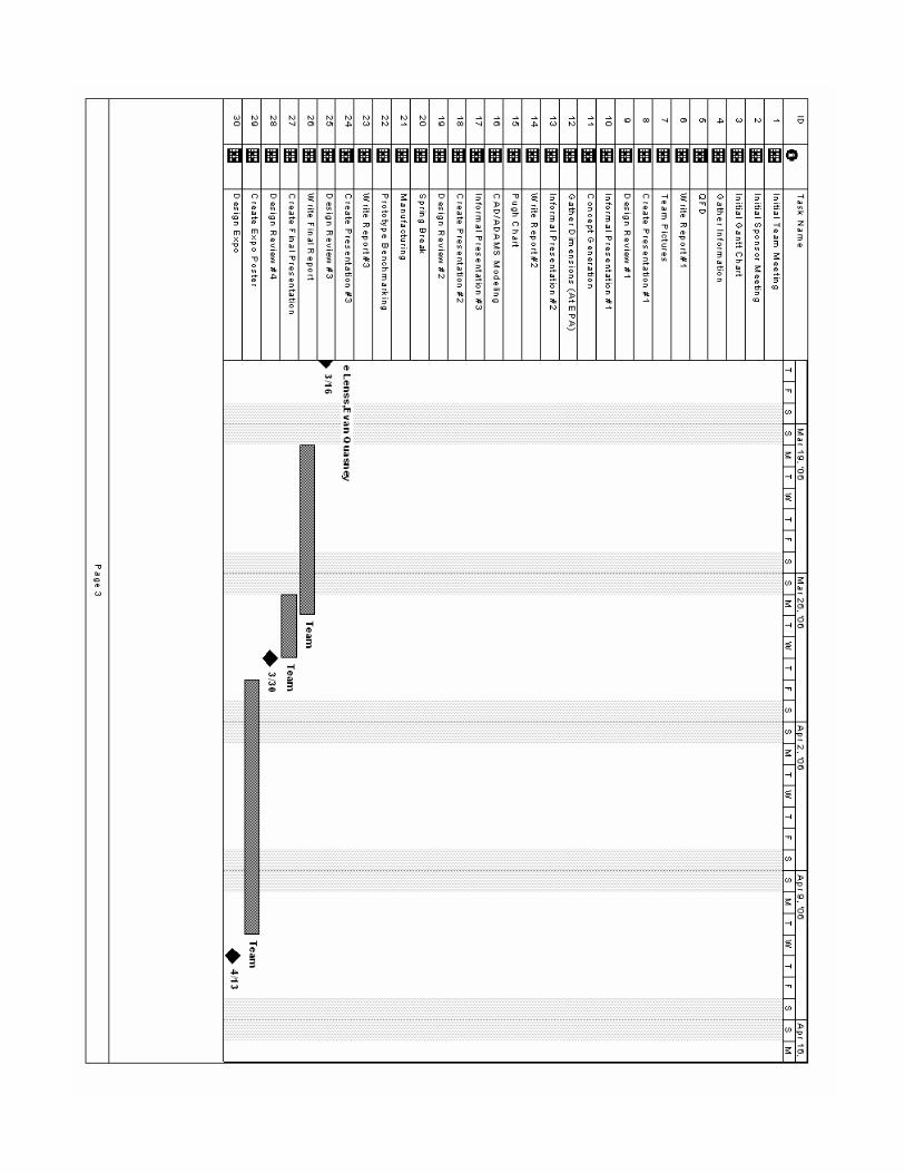
Appendix C. Gantt Chart


Appendix D: Design Concepts D1. – Snap Fits The piston and CV external snap fixture uses three fixture pieces joined to form an external ring around the pump assembly pieces. One of the external pieces would contain an extension to snap onto the CV and hold it in place during alignment. To assemble the pump using this fixture, the three pieces are first joined around the piston shafts and the CV joint connected to the CV snap extension. The pistons are then individually snapped into the fixture. The fixture is held against the barrel as the pistons are pushed and wiggled into their bores. After assembly the three fixture pieces could be disassembled for removal. Figure D1.1. Piston and CV External
Snap Fit
Figure D1.2. External Snap Fit with Magnet
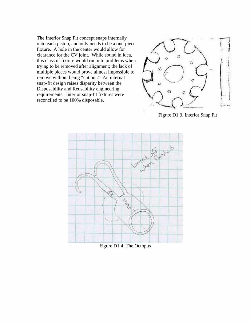
The Interior Snap Fit concept snaps internally onto each piston, and only needs to be a one-piece fixture. A hole in the center would allow for clearance for the CV joint. While sound in idea, this class of fixture would run into problems when trying to be removed after alignment; the lack of multiple pieces would prove almost impossible to remove without being “cut out.” An internal snap-fit design raises disparity between the Disposability and Reusability engineering requirements. Interior snap-fit fixtures were reconciled to be 100% disposable. Figure D1.3. Interior Snap Fit
Figure D1.4. The Octopus

D2. – Sleeve Concepts The sleeve with handles locates off the barrel, and would be put onto the pistons prior to their removal from the barrel. It would have two half-rings that would use attached handles to be force-fit around the barrels and pistons to grab each piston head and hold them in place. For assembly, the sleeve and handles would be aligned with the barrel, the barrel slid on until the pistons captured, and then the fixture removed.
Figure D2.1.Sleeve with Handles
Figure D2.2. Adaptable Snap Fit with Sleeve
This fixture has a metal outer ring to act as a “reference” surface with plastic inserts. Each insert would fit over the pistons, but would be thin enough that it could be easily removed and redesigned should the need arise. The plastic pieces would be held in place by a key-lock system, and each segment of the plastic-metal would dovetail into each other. Around the outside of the metal ring would be a sleeve that slid back and forth to locate on the barrel. After locating on the barrel, the entire assembly could be rotated left or right to line up and insert the pistons.

Magnets
Figure D2.3. Magnet Piston Alignment
D3. – Captive Designs
Figure D3.1. Knuckles
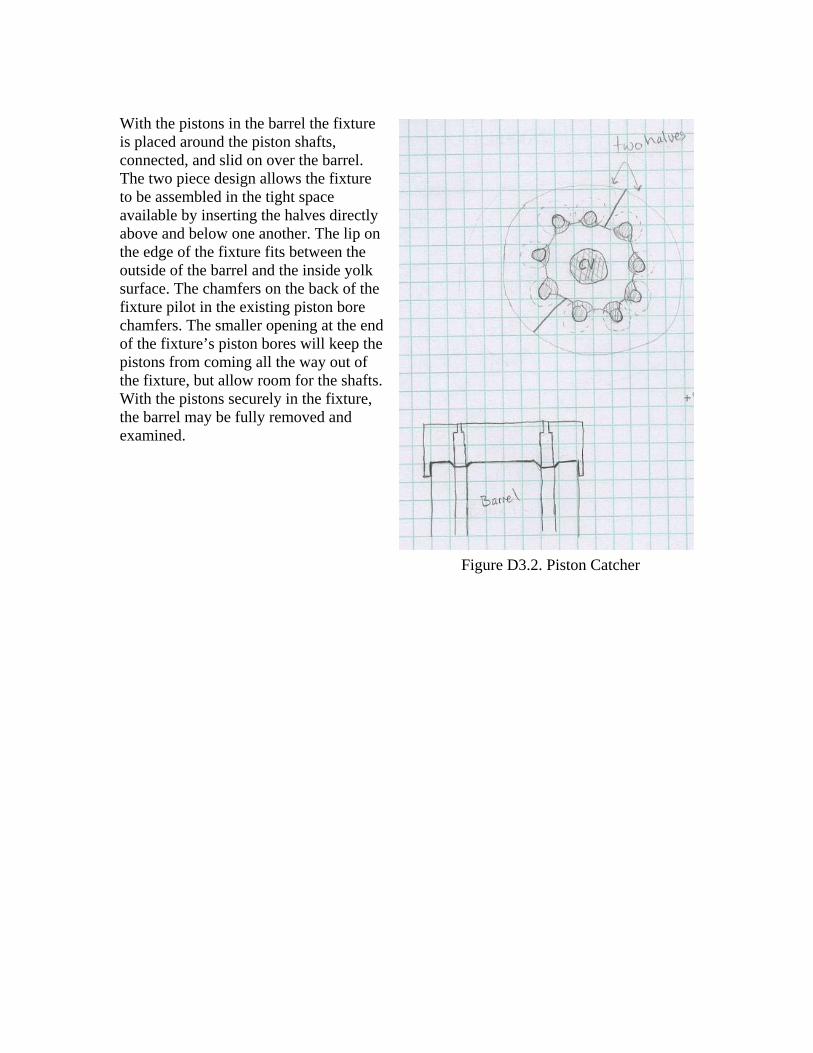
With the pistons in the barrel the fixture is placed around the piston shafts, connected, and slid on over the barrel. The two piece design allows the fixture to be assembled in the tight space available by inserting the halves directly above and below one another. The lip on the edge of the fixture fits between the outside of the barrel and the inside yolk surface. The chamfers on the back of the fixture pilot in the existing piston bore chamfers. The smaller opening at the end of the fixture’s piston bores will keep the pistons from coming all the way out of the fixture, but allow room for the shafts. With the pistons securely in the fixture, the barrel may be fully removed and examined.
Figure D3.2. Piston Catcher

D4. – CV Alignment Fixtures
Figure D4.1. The Razor
Figure D4.2. CV Snapper
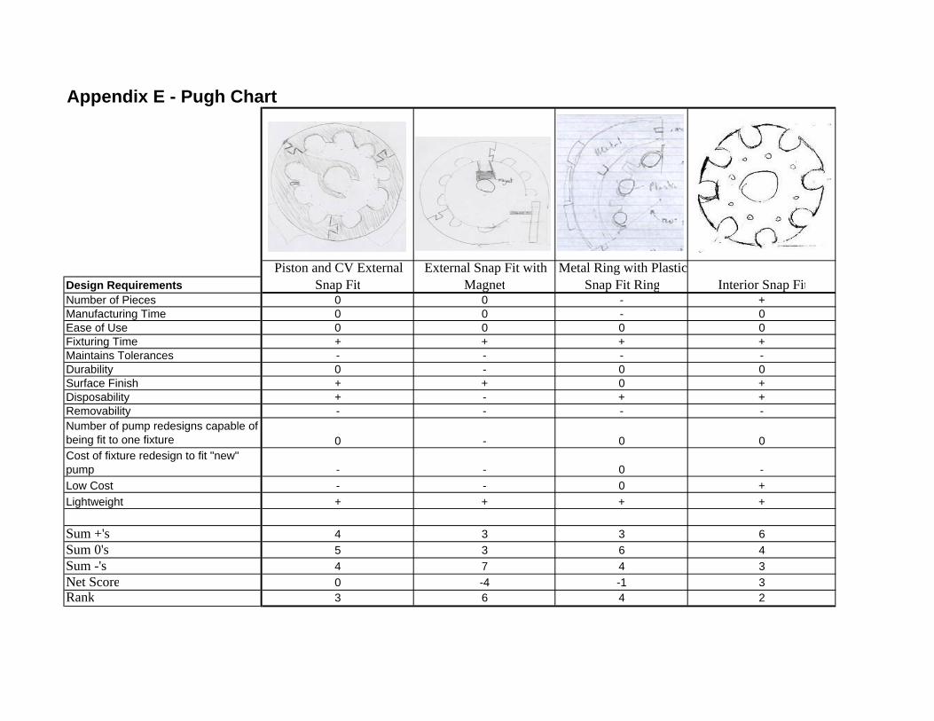
Appendix E - Pugh Chart
Design RequirementsNumber of Pieces 0 0 - +Manufacturing Time 0 0 - 0Ease of Use 0 0 0 0Fixturing Time + + + +Maintains Tolerances - - - -Durability 0 - 0 0Surface Finish + + 0 +Disposability + - + +Removability - - - -Number of pump redesigns capable of being fit to one fixture 0 - 0 0Cost of fixture redesign to fit "new" pump - - 0 -Low Cost - - 0 +Lightweight + + + +
Sum +'s 4 3 3 6Sum 0's 5 3 6 4Sum -'s 4 7 4 3Net Score 0 -4 -1 3Rank 3 6 4 2
Interior Snap FitPiston and CV External
Snap FitExternal Snap Fit with
MagnetMetal Ring with Plastic
Snap Fit Ring

- 0 0 +- - - +- + + 0+ 0 + ++ + 0 -+ + + -- + - +- - - +0 + + -
- 0 - 0
- 0 - -- - - +- + 0 +
3 6 4 71 4 3 29 3 6 4-6 3 -2 37 2 5 2
The OctopusMagnet AlignmentKnucklesSleeve with Handles

+ + ++ 0 ++ 0 ++ + ++ - ++ + +- + 0- - -+ + +
0 + 0
- 0 -0 + +0 + +
7 8 93 3 23 2 24 6 71 2 1
The RazorCV SnapperPiston Catcher

Appendix F – Engineering Prints for Alpha Prototype: The Razor

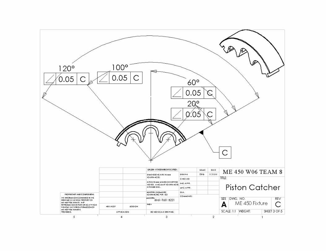
Appendix G – Engineering Prints for Final Design: Piston Catcher


Appendix G – Engineering Print for Final Design: The Razor

Appendix H – Bill of Materials
Inventory List: Bill of Materials
Level Inventor ID Name Source Contact Description Unit
Price Quantity Make/Buy
1 N/A Piston Alignment Fixture N/A N/A Fixture Assembly 1 Make
..2 N/A Piston Alignment Fixture Part N/A N/A Fixture Part 3 Make
….3 N/A 5" X 6" X 12" 6061-T651 Blank N/A N/A ME450 Team 8 Blanks for Fixture 4 Make
……4 8975K331 ASTM B221 - 5" X12" X 2.5" McMaster-Carr mcmaster.com 6061-T651 Aluminum Blank 84.31** 1 Buy
……4 5756K56 Flexible Magnets McMaster-Carr mcmaster.comAdhesive-Face Flexible Rare Earth Magnet 9.30** 1 Buy
……4 5756K36 Flexible Magnets McMaster-Carr mcmaster.com Plain-Face Flexible Rare Earth Magnet 6.90** 1 Buy
1 N/A Rapid Prototyped Alpha Model UM3D Lab Brett Lyons RP Alpha Concept 35.75 1 Buy
1 N/A Pump Mock-Up N/A N/A Hydraulic Pump Mock-Up 1 Make
..2 N/A Rapid Prototyped Pump Parts UM3D Lab Brett Lyons RP Barrel and RP Piston/Piston Shafts 118.45 1 Buy
..2 N/A Steel Sheets X50 Shop* Bob Coury Swash Plate 1 Make
..2 N/A Plexiglass X50 Shop* Bob Coury Yoke 1 Make
..2 N/A Aluminum Rod X50 Shop* Bob Coury Razor Shaft 1 Make 1 N/A Razor N/A N/A Shaft with Magnet on end 1 Make
……4 RECU-51235 End mill EWIE Co. Inc. Randy
Endmill 1/16” Diameter Single End 2 Fluted M42 Cobalt with 3/16” Shank 12.00 1 Buy
1 N/A 3’ X 4’ Poster Printing Groundworks N/A Design Expo Poster 60.00 1 Buy
……4 N/A Miscellaneous Hardware X50 Shop* Robert Coury
Miscellaneous Hardware used for clamping during machining 30 N/A
N/A TOTAL Total N/A N/A Total product cost with shipping and handling 337.67 N/A N/A
*Not a tool or test equipment **Total Shipping and Handling costs were $11.05

Appendix I – Rapid Prototype
A full scale plaster mock up of the final design was fabricated using rapid prototyping at the University of Michigan 3D Lab using a ZCorp 310 RP machine. The prototype material is ZP102; this material is a composition of 55% density by volume of 90-10 calcium sulfate-glass bead bonded powder, and 45% density by volume of high DP epoxy from West Systems. The layer thickness of the rapid prototyping process is 100 µm. The material typically has an ultimate compressive strength of1.4 MPa, and an ultimate tensile strength of 10 MPa with less than 1% elongation. Part strength is highly dictated by the geometry of the part. This means the prototype will not demonstrate the structural qualities of the final aluminum design; it will solely test the feasibility of assembly with the fixture on a bent axis pump.
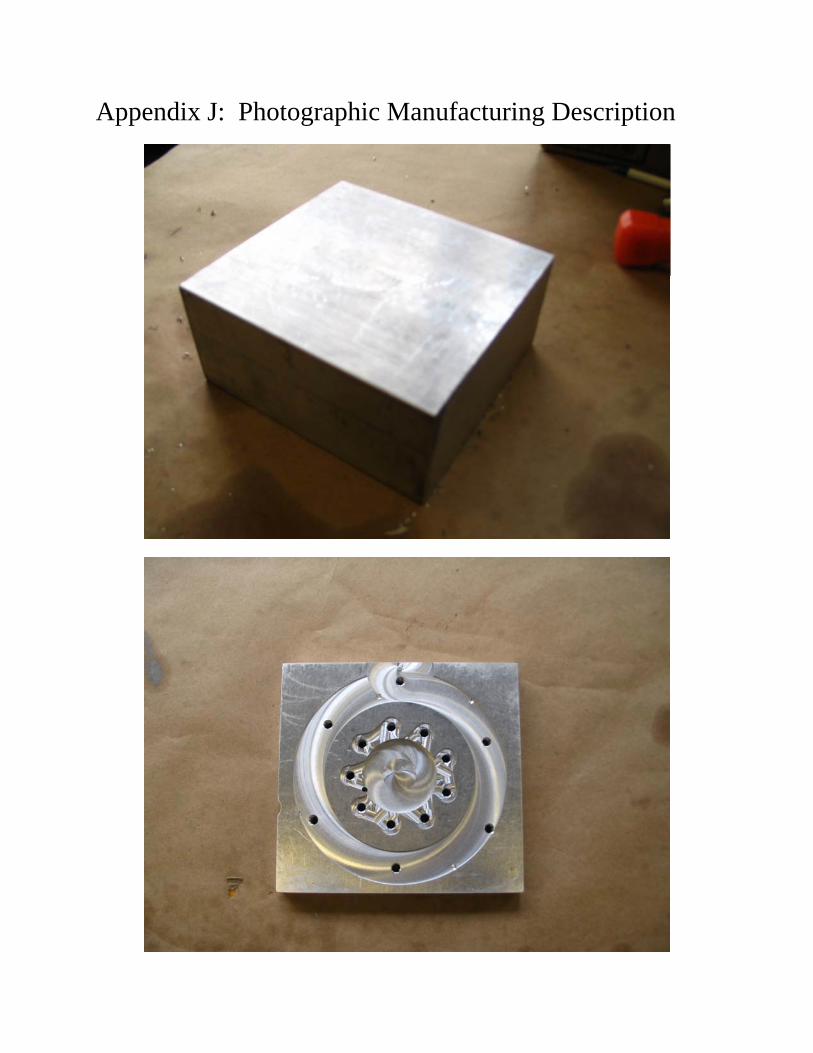
Appendix J: Photographic Manufacturing Description


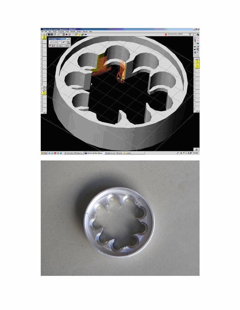

Appendix K Assembly of Bent Axis Pump with Piston Alignment Fixture 4/18/2006
designsafe Report
Application: Assembly of Bent Axis Pump with Piston Alignment Fixture Analyst Name(s): Sabrina Hall, David Lenss, Evan Quasney, Kristina Tolbert
This assessment describes the assembly of a bent axis
pump using a piston alignment fixture. The process involves
attachment of the fixture, alignment of piston shafts with the
barrel, and insertion of the piston shafts into the barrel.
Description: Company: Environmental Protection Agency (EPA)
Facility Location: United States Environmental Protection Agency
National Vehicle and Fuel Emissions Laboratory
2565 Plymouth Road
Ann Arbor, MI 48105
(734) 214-4200
Product Identifier: Piston Alignment Fixture
Assessment Type: Preliminary
Limits: Assembly of the bent axis pump utilizing the fixture must be
completed by one user in less than ten minutes; this must be
completed without damaging the apparatus or causing
personal harm to the user.
Sources: See Reference Section
Guide sentence: When doing [task], the [user] could be injured by the [hazard] due to the [failure mode].
ResponsibleHazard /
Task
User /
Failure Mode
Risk Reduction Methods
Status / Sub-process /
Initial Assessment
Severity
Exposure
Probability Risk Level
Final Assessment
Severity
Exposure
Probability Risk Level/Comments /Reference
None / Other : Not a hazard
N/A
Wear Safety Glasses
All Users
All Tasks
LowMinimal
None
Negligible
N/A Minimal
None
Negligible
Low Complete [4/18/2006]
Operator
slips / trips / falls : slip
Bodily harm
Drain Hydrolic Fluid
operator
lubrication
LowSlight
Remote
Unlikely
Clean work area, wear proper
shoes.
Slight
Remote
Unlikely
Low Complete [4/18/2006]
Operator
slips / trips / falls : fall hazard
from elevated work
Bodily harm
Drain Hydrolic Fluid
operator
lubrication
ModerateSerious
Remote
Unlikely
Have a spotter. Serious
Remote
Unlikely
Moderate Complete [4/18/2006]
Operator
slips / trips / falls : instability
Bodily harm
Drain Hydrolic Fluid
operator
lubrication
LowSlight
Remote
Unlikely
Have a spotter. Slight
Remote
Unlikely
Low Complete [4/18/2006]
Operator
chemical : reaction to / with
chemicals
Bodily harm
Drain Hydrolic Fluid
operator
lubrication
LowSlight
Remote
Unlikely
Wear gloves. Slight
Remote
Unlikely
Low Complete [4/18/2006]
Operator
fluid / pressure : high pressure
coolant
Pump failure
Drain Hydrolic Fluid
operator
lubrication
HighSerious
Frequent
Possible
Inspect machine regularly. Serious
Frequent
Possible
High Complete [4/18/2006]
Operator
fluid / pressure : fluid leakage /
ejection
Pump failure
Drain Hydrolic Fluid
operator
lubrication
HighSlight
Frequent
Possible
Inspect machine regularly. Slight
Frequent
Possible
High Complete [4/18/2006]
Operator
slips / trips / falls : slip
Bodily harm
Drain Hydrolic Fluid
operator
clean machine
LowSlight
Remote
Unlikely
Clean work area, wear proper
shoes.
Slight
Remote
Unlikely
Low Complete [4/18/2006]
Operator
Page 1

Appendix K Assembly of Bent Axis Pump with Piston Alignment Fixture 4/18/2006
ResponsibleHazard /
Task
User /
Failure Mode
Risk Reduction Methods
Status / Sub-process /
Initial Assessment
Severity
Exposure
Probability Risk Level
Final Assessment
Severity
Exposure
Probability Risk Level/Comments /Reference
slips / trips / falls : fall hazard
from elevated work
Bodily harm
Drain Hydrolic Fluid
operator
clean machine
ModerateSerious
Remote
Unlikely
Have a spotter. Serious
Remote
Unlikely
Moderate Complete [4/18/2006]
Operator
slips / trips / falls : instability
Bodily harm
Drain Hydrolic Fluid
operator
clean machine
LowSlight
Remote
Unlikely
Have a spotter. Slight
Remote
Unlikely
Low Complete [4/18/2006]
Operator
chemical : reaction to / with
chemicals
Bodily harm
Drain Hydrolic Fluid
operator
clean machine
LowSlight
Remote
Unlikely
Wear gloves. Slight
Remote
Unlikely
Low Complete [4/18/2006]
Operator
fluid / pressure : fluid leakage /
ejection
Pump failure
Drain Hydrolic Fluid
operator
clean machine
HighSlight
Frequent
Possible
Inspect machine regularly. Slight
Frequent
Possible
High Complete [4/18/2006]
Operator
slips / trips / falls : fall hazard
from elevated work
Bodily harm
Open Bent Axis Pump
Housing
operator
load / unload materials
ModerateCatastrophic
Remote
Unlikely
Have a spotter. Catastrophic
Remote
Unlikely
Moderate Complete [4/18/2006]
Operator
slips / trips / falls : object
falling onto
Bodily harm
Open Bent Axis Pump
Housing
operator
load / unload materials
ModerateCatastrophic
Remote
Unlikely
Be careful. Catastrophic
Remote
Unlikely
Moderate Complete [4/18/2006]
Operator
ergonomics / human factors :
excessive force / exertion
Pump failure
Open Bent Axis Pump
Housing
operator
load / unload materials
ModerateSlight
Occasional
Unlikely
Have a spotter. Slight
Occasional
Unlikely
Moderate Complete [4/18/2006]
Operator
ergonomics / human factors :
lifting / bending / twisting
Pump failure
Open Bent Axis Pump
Housing
operator
load / unload materials
ModerateSlight
Occasional
Unlikely
Have a spotter. Slight
Occasional
Unlikely
Moderate Complete [4/18/2006]
Operator
ergonomics / human factors :
human errors / behaviors
Bodily harm
Open Bent Axis Pump
Housing
operator
load / unload materials
LowMinimal
Remote
Unlikely
N/A Minimal
Remote
Unlikely
Low Complete [4/18/2006]
Operator
material handling : storing
Bodily harm
Open Bent Axis Pump
Housing
operator
load / unload materials
ModerateSerious
Remote
Unlikely
N/A Serious
Remote
Unlikely
Moderate Complete [4/18/2006]
Operator
material handling : movement
to / from storage
Bodily harm
Open Bent Axis Pump
Housing
operator
load / unload materials
ModerateSerious
Remote
Unlikely
Have a spotter. Serious
Remote
Unlikely
Moderate Complete [4/18/2006]
Operator
Page 2

Appendix K Assembly of Bent Axis Pump with Piston Alignment Fixture 4/18/2006
ResponsibleHazard /
Task
User /
Failure Mode
Risk Reduction Methods
Status / Sub-process /
Initial Assessment
Severity
Exposure
Probability Risk Level
Final Assessment
Severity
Exposure
Probability Risk Level/Comments /Reference
material handling : excessive
weight
Bodily harm
Open Bent Axis Pump
Housing
operator
load / unload materials
ModerateCatastrophic
Remote
Unlikely
Have a spotter. Catastrophic
Remote
Unlikely
Moderate Complete [4/18/2006]
Operator
fluid / pressure : high pressure
coolant
Pump failure
Open Bent Axis Pump
Housing
operator
load / unload materials
HighSerious
Frequent
Possible
Inspect machine regularly. Serious
Frequent
Possible
High Complete [4/18/2006]
Operator
fluid / pressure : fluid leakage /
ejection
Pump failure
Open Bent Axis Pump
Housing
operator
load / unload materials
HighSlight
Frequent
Possible
Inspect machine regularly. Slight
Frequent
Possible
High Complete [4/18/2006]
Operator
slips / trips / falls : debris
Bodily harm
Set Oriention of Yoke,
Barrel, and Piston Shafts to
Proper Locations
operator
sort / inspect parts
LowSlight
Remote
Unlikely
Wear gloves. Slight
Remote
Unlikely
Low Complete [4/18/2006]
Operator
ergonomics / human factors :
repetition
Bodily harm
Set Oriention of Yoke,
Barrel, and Piston Shafts to
Proper Locations
operator
sort / inspect parts
ModerateSlight
Frequent
Unlikely
N/A Slight
Frequent
Unlikely
Moderate Complete [4/18/2006]
Operator
confined spaces : confined
spaces
Bodily harm
Set Oriention of Yoke,
Barrel, and Piston Shafts to
Proper Locations
operator
sort / inspect parts
ModerateSlight
Frequent
Unlikely
N/A Slight
Frequent
Unlikely
Moderate Complete [4/18/2006]
Operator
chemical : reaction to / with
chemicals
Bodily harm
Set Oriention of Yoke,
Barrel, and Piston Shafts to
Proper Locations
operator
sort / inspect parts
LowSlight
Remote
Unlikely
Wear gloves. Slight
Remote
Unlikely
Low Complete [4/18/2006]
Operator
slips / trips / falls : debris
Bodily harm
Set Oriention of Yoke,
Barrel, and Piston Shafts to
Proper Locations
operator
position / fasten parts and
components
LowSlight
Remote
Unlikely
Wear gloves. Slight
Remote
Unlikely
Low Complete [4/18/2006]
Operator
Page 3

Appendix K Assembly of Bent Axis Pump with Piston Alignment Fixture 4/18/2006
ResponsibleHazard /
Task
User /
Failure Mode
Risk Reduction Methods
Status / Sub-process /
Initial Assessment
Severity
Exposure
Probability Risk Level
Final Assessment
Severity
Exposure
Probability Risk Level/Comments /Reference
ergonomics / human factors :
repetition
Bodily harm
Set Oriention of Yoke,
Barrel, and Piston Shafts to
Proper Locations
operator
position / fasten parts and
components
ModerateSlight
Frequent
Unlikely
N/A Slight
Frequent
Unlikely
Moderate Complete [4/18/2006]
Operator
confined spaces : confined
spaces
Bodily harm
Set Oriention of Yoke,
Barrel, and Piston Shafts to
Proper Locations
operator
position / fasten parts and
components
ModerateSlight
Frequent
Unlikely
N/A Slight
Frequent
Unlikely
Moderate Complete [4/18/2006]
Operator
chemical : reaction to / with
chemicals
Bodily harm
Set Oriention of Yoke,
Barrel, and Piston Shafts to
Proper Locations
operator
position / fasten parts and
components
LowSlight
Remote
Unlikely
Wear gloves. Slight
Remote
Unlikely
Low Complete [4/18/2006]
Operator
slips / trips / falls : impact to /
with
Bodily harm
Attach Primary Piece of
Piston Alignment Fixture
operator
position / fasten parts and
components
ModerateSlight
Frequent
Unlikely
N/A Slight
Frequent
Unlikely
Moderate Complete [4/18/2006]
Operator
slips / trips / falls : instability
Bodily harm
Attach Primary Piece of
Piston Alignment Fixture
operator
position / fasten parts and
components
LowSlight
Remote
Unlikely
N/A Slight
Remote
Unlikely
Low Complete [4/18/2006]
Operator
ergonomics / human factors :
posture
Bodily harm
Attach Primary Piece of
Piston Alignment Fixture
operator
position / fasten parts and
components
LowSlight
Remote
Unlikely
N/A Slight
Remote
Unlikely
Low Complete [4/18/2006]
Operator
ergonomics / human factors :
repetition
Bodily harm
Attach Primary Piece of
Piston Alignment Fixture
operator
position / fasten parts and
components
ModerateSlight
Frequent
Unlikely
N/A Slight
Frequent
Unlikely
Moderate Complete [4/18/2006]
Operator
Page 4

Appendix K Assembly of Bent Axis Pump with Piston Alignment Fixture 4/18/2006
ResponsibleHazard /
Task
User /
Failure Mode
Risk Reduction Methods
Status / Sub-process /
Initial Assessment
Severity
Exposure
Probability Risk Level
Final Assessment
Severity
Exposure
Probability Risk Level/Comments /Reference
ergonomics / human factors :
human errors / behaviors
Bodily harm
Attach Primary Piece of
Piston Alignment Fixture
operator
position / fasten parts and
components
LowSlight
Remote
Unlikely
N/A Slight
Remote
Unlikely
Low Complete [4/18/2006]
Operator
confined spaces : confined
spaces
Bodily harm
Attach Primary Piece of
Piston Alignment Fixture
operator
position / fasten parts and
components
ModerateSlight
Frequent
Unlikely
N/A Slight
Frequent
Unlikely
Moderate Complete [4/18/2006]
Operator
chemical : reaction to / with
chemicals
Bodily harm
Attach Primary Piece of
Piston Alignment Fixture
operator
position / fasten parts and
components
LowSlight
Remote
Unlikely
Wear gloves. Slight
Remote
Unlikely
Low Complete [4/18/2006]
Operator
slips / trips / falls : impact to /
with
Bodily harm
Attach Seondary Piece of
Piston Alignment Fixture
operator
position / fasten parts and
components
ModerateSlight
Frequent
Unlikely
N/A Slight
Frequent
Unlikely
Moderate Complete [4/18/2006]
Operator
slips / trips / falls : instability
Bodily harm
Attach Seondary Piece of
Piston Alignment Fixture
operator
position / fasten parts and
components
LowSlight
Remote
Unlikely
N/A Slight
Remote
Unlikely
Low Complete [4/18/2006]
Operator
ergonomics / human factors :
posture
Bodily harm
Attach Seondary Piece of
Piston Alignment Fixture
operator
position / fasten parts and
components
LowSlight
Remote
Unlikely
N/A Slight
Remote
Unlikely
Low Complete [4/18/2006]
Operator
ergonomics / human factors :
repetition
Bodily harm
Attach Seondary Piece of
Piston Alignment Fixture
operator
position / fasten parts and
components
ModerateSlight
Frequent
Unlikely
N/A Slight
Frequent
Unlikely
Moderate Complete [4/18/2006]
Operator
ergonomics / human factors :
human errors / behaviors
Bodily harm
Attach Seondary Piece of
Piston Alignment Fixture
operator
position / fasten parts and
components
LowSlight
Remote
Unlikely
N/A Slight
Remote
Unlikely
Low Complete [4/18/2006]
Operator
Page 5

Appendix K Assembly of Bent Axis Pump with Piston Alignment Fixture 4/18/2006
ResponsibleHazard /
Task
User /
Failure Mode
Risk Reduction Methods
Status / Sub-process /
Initial Assessment
Severity
Exposure
Probability Risk Level
Final Assessment
Severity
Exposure
Probability Risk Level/Comments /Reference
confined spaces : confined
spaces
Bodily harm
Attach Seondary Piece of
Piston Alignment Fixture
operator
position / fasten parts and
components
ModerateSlight
Frequent
Unlikely
N/A Slight
Frequent
Unlikely
Moderate Complete [4/18/2006]
Operator
chemical : reaction to / with
chemicals
Bodily harm
Attach Seondary Piece of
Piston Alignment Fixture
operator
position / fasten parts and
components
LowSlight
Remote
Unlikely
Wear gloves. Slight
Remote
Unlikely
Low Complete [4/18/2006]
Operator
slips / trips / falls : impact to /
with
Bodily harm
Attach Final Piece of Piston
Alignment Fixture
operator
position / fasten parts and
components
ModerateSlight
Frequent
Unlikely
N/A Slight
Frequent
Unlikely
Moderate Complete [4/18/2006]
Operator
slips / trips / falls : instability
Bodily harm
Attach Final Piece of Piston
Alignment Fixture
operator
position / fasten parts and
components
LowSlight
Remote
Unlikely
N/A Slight
Remote
Unlikely
Low Complete [4/18/2006]
Operator
ergonomics / human factors :
posture
Bodily harm
Attach Final Piece of Piston
Alignment Fixture
operator
position / fasten parts and
components
LowSlight
Remote
Unlikely
N/A Slight
Remote
Unlikely
Low Complete [4/18/2006]
Operator
ergonomics / human factors :
repetition
Bodily harm
Attach Final Piece of Piston
Alignment Fixture
operator
position / fasten parts and
components
ModerateSlight
Frequent
Unlikely
N/A Slight
Frequent
Unlikely
Moderate Complete [4/18/2006]
Operator
ergonomics / human factors :
human errors / behaviors
Bodily harm
Attach Final Piece of Piston
Alignment Fixture
operator
position / fasten parts and
components
LowSlight
Remote
Unlikely
N/A Slight
Remote
Unlikely
Low Complete [4/18/2006]
Operator
confined spaces : confined
spaces
Bodily harm
Attach Final Piece of Piston
Alignment Fixture
operator
position / fasten parts and
components
ModerateSlight
Frequent
Unlikely
N/A Slight
Frequent
Unlikely
Moderate Complete [4/18/2006]
Operator
Page 6

Appendix K Assembly of Bent Axis Pump with Piston Alignment Fixture 4/18/2006
ResponsibleHazard /
Task
User /
Failure Mode
Risk Reduction Methods
Status / Sub-process /
Initial Assessment
Severity
Exposure
Probability Risk Level
Final Assessment
Severity
Exposure
Probability Risk Level/Comments /Reference
chemical : reaction to / with
chemicals
Bodily harm
Attach Final Piece of Piston
Alignment Fixture
operator
position / fasten parts and
components
LowSlight
Remote
Unlikely
Wear gloves. Slight
Remote
Unlikely
Low Complete [4/18/2006]
Operator
slips / trips / falls : debris
Bodily harm
Remove Barrel
operator
sort / inspect parts
LowSlight
Remote
Unlikely
Wear gloves. Slight
Remote
Unlikely
Low Complete [4/18/2006]
Operator
ergonomics / human factors :
repetition
Bodily harm
Remove Barrel
operator
sort / inspect parts
ModerateSlight
Frequent
Unlikely
N/A Slight
Frequent
Unlikely
Moderate Complete [4/18/2006]
Operator
confined spaces : confined
spaces
Bodily harm
Remove Barrel
operator
sort / inspect parts
ModerateSlight
Frequent
Unlikely
N/A Slight
Frequent
Unlikely
Moderate Complete [4/18/2006]
Operator
chemical : reaction to / with
chemicals
Bodily harm
Remove Barrel
operator
sort / inspect parts
LowSlight
Remote
Unlikely
N/A Slight
Remote
Unlikely
Low Complete [4/18/2006]
Operator
slips / trips / falls : debris
Bodily harm
Remove Barrel
operator
position / fasten parts and
components
LowSlight
Remote
Unlikely
Wear gloves. Slight
Remote
Unlikely
Low Complete [4/18/2006]
Operator
slips / trips / falls : object
falling onto
Bodily harm
Remove Barrel
operator
position / fasten parts and
components
ModerateSerious
Remote
Unlikely
Be careful. Serious
Remote
Unlikely
Moderate Complete [4/18/2006]
Operator
ergonomics / human factors :
repetition
Bodily harm
Remove Barrel
operator
position / fasten parts and
components
ModerateSlight
Frequent
Unlikely
N/A Slight
Frequent
Unlikely
Moderate Complete [4/18/2006]
Operator
confined spaces : confined
spaces
Bodily harm
Remove Barrel
operator
position / fasten parts and
components
ModerateSlight
Frequent
Unlikely
N/A Slight
Frequent
Unlikely
Moderate Complete [4/18/2006]
Operator
chemical : reaction to / with
chemicals
Bodily harm
Remove Barrel
operator
position / fasten parts and
components
LowSlight
Remote
Unlikely
Wear gloves. Slight
Remote
Unlikely
Low Complete [4/18/2006]
Operator
Page 7

Appendix K Assembly of Bent Axis Pump with Piston Alignment Fixture 4/18/2006
ResponsibleHazard /
Task
User /
Failure Mode
Risk Reduction Methods
Status / Sub-process /
Initial Assessment
Severity
Exposure
Probability Risk Level
Final Assessment
Severity
Exposure
Probability Risk Level/Comments /Reference
slips / trips / falls : impact to /
with
Bodily harm
Remove Barrel
operator
special task(s) - barrel
changeout
ModerateSerious
Remote
Unlikely
N/A Serious
Remote
Unlikely
Moderate Complete [4/18/2006]
Operator
slips / trips / falls : object
falling onto
Bodily harm
Remove Barrel
operator
special task(s) - barrel
changeout
ModerateSerious
Remote
Unlikely
Be careful. Serious
Remote
Unlikely
Moderate Complete [4/18/2006]
Operator
ergonomics / human factors :
lifting / bending / twisting
Pump failure
Remove Barrel
operator
special task(s) - barrel
changeout
ModerateSlight
Occasional
Unlikely
N/A Slight
Occasional
Unlikely
Moderate Complete [4/18/2006]
Operator
material handling : storing
Bodily harm
Remove Barrel
operator
special task(s) - barrel
changeout
LowSlight
Remote
Unlikely
N/A Slight
Remote
Unlikely
Low Complete [4/18/2006]
Operator
material handling : movement
to / from storage
Bodily harm
Remove Barrel
operator
special task(s) - barrel
changeout
LowSlight
Remote
Unlikely
Have a spotter. Slight
Remote
Unlikely
Low Complete [4/18/2006]
Operator
confined spaces : confined
spaces
Bodily harm
Remove Barrel
operator
special task(s) - barrel
changeout
ModerateSlight
Frequent
Unlikely
N/A Slight
Frequent
Unlikely
Moderate Complete [4/18/2006]
Operator
chemical : reaction to / with
chemicals
Bodily harm
Remove Barrel
operator
special task(s) - barrel
changeout
LowSlight
Remote
Unlikely
Wear gloves. Slight
Remote
Unlikely
Low Complete [4/18/2006]
Operator
slips / trips / falls : debris
Bodily harm
Run Diagnostics on Barrel
operator
sort / inspect parts
LowSlight
Remote
Unlikely
Wear gloves. Slight
Remote
Unlikely
Low Complete [4/18/2006]
Operator
ergonomics / human factors :
repetition
Bodily harm
Run Diagnostics on Barrel
operator
sort / inspect parts
ModerateSlight
Frequent
Unlikely
N/A Slight
Frequent
Unlikely
Moderate Complete [4/18/2006]
Operator
confined spaces : confined
spaces
Bodily harm
Run Diagnostics on Barrel
operator
sort / inspect parts
ModerateSlight
Frequent
Unlikely
N/A Slight
Frequent
Unlikely
Moderate Complete [4/18/2006]
Operator
chemical : reaction to / with
chemicals
Bodily harm
Run Diagnostics on Barrel
operator
sort / inspect parts
LowSlight
Remote
Unlikely
Wear gloves. Slight
Remote
Unlikely
Low Complete [4/18/2006]
Operator
Page 8

Appendix K Assembly of Bent Axis Pump with Piston Alignment Fixture 4/18/2006
ResponsibleHazard /
Task
User /
Failure Mode
Risk Reduction Methods
Status / Sub-process /
Initial Assessment
Severity
Exposure
Probability Risk Level
Final Assessment
Severity
Exposure
Probability Risk Level/Comments /Reference
slips / trips / falls : debris
Bodily harm
Run Diagnostics on Barrel
operator
basic troubleshooting
LowSlight
Remote
Unlikely
Wear gloves. Slight
Remote
Unlikely
Low Complete [4/18/2006]
Operator
slips / trips / falls : object
falling onto
Bodily harm
Run Diagnostics on Barrel
operator
basic troubleshooting
ModerateSerious
Remote
Unlikely
N/A Serious
Remote
Unlikely
Moderate Complete [4/18/2006]
Operator
ergonomics / human factors :
duration
Bodily harm
Run Diagnostics on Barrel
operator
basic troubleshooting
LowSlight
Remote
Unlikely
N/A Slight
Remote
Unlikely
Low Complete [4/18/2006]
Operator
ergonomics / human factors :
human errors / behaviors
Bodily harm
Run Diagnostics on Barrel
operator
basic troubleshooting
LowSlight
Remote
Unlikely
N/A Slight
Remote
Unlikely
Low Complete [4/18/2006]
Operator
noise / vibration : equipment
damage
Pump failure
Run Diagnostics on Barrel
operator
basic troubleshooting
ModerateSerious
Remote
Unlikely
N/A Serious
Remote
Unlikely
Moderate Complete [4/18/2006]
Operator
noise / vibration : fatigue /
material strength
Pump failure
Run Diagnostics on Barrel
operator
basic troubleshooting
LowSlight
Remote
Unlikely
N/A Slight
Remote
Unlikely
Low Complete [4/18/2006]
Operator
confined spaces : confined
spaces
Bodily harm
Run Diagnostics on Barrel
operator
basic troubleshooting
ModerateSlight
Frequent
Unlikely
N/A Slight
Frequent
Unlikely
Moderate Complete [4/18/2006]
Operator
environmental / industrial
hygiene : contamination
Pump failure
Run Diagnostics on Barrel
operator
basic troubleshooting
LowSlight
Remote
Unlikely
N/A Slight
Remote
Unlikely
Low Complete [4/18/2006]
Operator
chemical : reaction to / with
chemicals
Bodily harm
Run Diagnostics on Barrel
operator
basic troubleshooting
LowSlight
Remote
Unlikely
N/A Slight
Remote
Unlikely
Low Complete [4/18/2006]
Operator
chemical : failure at key points
and trouble spots
Pump failure
Run Diagnostics on Barrel
operator
basic troubleshooting
ModerateSerious
Remote
Unlikely
Inspect machine regularly. Serious
Remote
Unlikely
Moderate Complete [4/18/2006]
Operator
slips / trips / falls : debris
Bodily harm
Run Diagnostics on Barrel
operator
special task(s) - barrel
changeout
LowSlight
Remote
Unlikely
Wear gloves. Slight
Remote
Unlikely
Low Complete [4/18/2006]
Operator
slips / trips / falls : object
falling onto
Bodily harm
Run Diagnostics on Barrel
operator
special task(s) - barrel
changeout
ModerateSerious
Remote
Unlikely
Be careful. Serious
Remote
Unlikely
Moderate Complete [4/18/2006]
Operator
Page 9
Appendix K Assembly of Bent Axis Pump with Piston Alignment Fixture 4/18/2006
ResponsibleHazard /
Task
User /
Failure Mode
Risk Reduction Methods
Status / Sub-process /
Initial Assessment
Severity
Exposure
Probability Risk Level
Final Assessment
Severity
Exposure
Probability Risk Level/Comments /Reference
confined spaces : confined
spaces
Bodily harm
Run Diagnostics on Barrel
operator
special task(s) - barrel
changeout
ModerateSlight
Frequent
Unlikely
N/A Slight
Frequent
Unlikely
Moderate Complete [4/18/2006]
Operator
chemical : reaction to / with
chemicals
Bodily harm
Run Diagnostics on Barrel
operator
special task(s) - barrel
changeout
LowSlight
Remote
Unlikely
Wear gloves. Slight
Remote
Unlikely
Low Complete [4/18/2006]
Operator
slips / trips / falls : debris
Bodily harm
Attach Barrel
operator
position / fasten parts and
components
LowSlight
Remote
Unlikely
Wear gloves. Slight
Remote
Unlikely
Low Complete [4/18/2006]
Operator
slips / trips / falls : object
falling onto
Bodily harm
Attach Barrel
operator
position / fasten parts and
components
ModerateSerious
Remote
Unlikely
Be careful. Serious
Remote
Unlikely
Moderate Complete [4/18/2006]
Operator
confined spaces : confined
spaces
Bodily harm
Attach Barrel
operator
position / fasten parts and
components
ModerateSlight
Frequent
Unlikely
N/A Slight
Frequent
Unlikely
Moderate Complete [4/18/2006]
Operator
chemical : reaction to / with
chemicals
Bodily harm
Attach Barrel
operator
position / fasten parts and
components
LowSlight
Remote
Unlikely
Wear gloves. Slight
Remote
Unlikely
Low Complete [4/18/2006]
Operator
slips / trips / falls : debris
Bodily harm
Remove All Fixture Pieces
operator
finishing task(s)
LowSlight
Remote
Unlikely
Wear gloves. Slight
Remote
Unlikely
Low Complete [4/18/2006]
Operator
slips / trips / falls : impact to /
with
Bodily harm
Remove All Fixture Pieces
operator
finishing task(s)
LowSlight
Remote
Unlikely
N/A Slight
Remote
Unlikely
Low Complete [4/18/2006]
Operator
ergonomics / human factors :
human errors / behaviors
Bodily harm
Remove All Fixture Pieces
operator
finishing task(s)
LowSlight
Remote
Unlikely
N/A Slight
Remote
Unlikely
Low Complete [4/18/2006]
Operator
noise / vibration : equipment
damage
Fixture failure
Remove All Fixture Pieces
operator
finishing task(s)
ModerateSerious
Remote
Unlikely
N/A Serious
Remote
Unlikely
Moderate Complete [4/18/2006]
Operator
noise / vibration : fatigue /
material strength
Fixture failure
Remove All Fixture Pieces
operator
finishing task(s)
LowSlight
Remote
Unlikely
N/A Slight
Remote
Unlikely
Low Complete [4/18/2006]
Operator
Page 10

Appendix K Assembly of Bent Axis Pump with Piston Alignment Fixture 4/18/2006
ResponsibleHazard /
Task
User /
Failure Mode
Risk Reduction Methods
Status / Sub-process /
Initial Assessment
Severity
Exposure
Probability Risk Level
Final Assessment
Severity
Exposure
Probability Risk Level/Comments /Reference
material handling : storing
Bodily harm
Remove All Fixture Pieces
operator
finishing task(s)
LowSlight
Remote
Unlikely
N/A Slight
Remote
Unlikely
Low Complete [4/18/2006]
Operator
material handling : movement
to / from storage
Bodily harm
Remove All Fixture Pieces
operator
finishing task(s)
LowSlight
Remote
Unlikely
Have a spotter. Slight
Remote
Unlikely
Low Complete [4/18/2006]
Operator
confined spaces : confined
spaces
Bodily harm
Remove All Fixture Pieces
operator
finishing task(s)
ModerateSlight
Frequent
Unlikely
N/A Slight
Frequent
Unlikely
Moderate Complete [4/18/2006]
Operator
chemical : reaction to / with
chemicals
Bodily harm
Remove All Fixture Pieces
operator
finishing task(s)
LowSlight
Remote
Unlikely
Wear gloves. Slight
Remote
Unlikely
Low Complete [4/18/2006]
Operator
slips / trips / falls : fall hazard
from elevated work
Bodily harm
Close Bent Axis Pump
Housing
operator
load / unload materials
ModerateCatastrophic
Remote
Unlikely
Have a spotter. Catastrophic
Remote
Unlikely
Moderate Complete [4/18/2006]
Operator
slips / trips / falls : object
falling onto
Bodily harm
Close Bent Axis Pump
Housing
operator
load / unload materials
ModerateCatastrophic
Remote
Unlikely
Be careful. Catastrophic
Remote
Unlikely
Moderate Complete [4/18/2006]
Operator
ergonomics / human factors :
excessive force / exertion
Pump failure
Close Bent Axis Pump
Housing
operator
load / unload materials
ModerateSlight
Occasional
Unlikely
Have a spotter. Slight
Occasional
Unlikely
Moderate Complete [4/18/2006]
Operator
ergonomics / human factors :
lifting / bending / twisting
Pump failure
Close Bent Axis Pump
Housing
operator
load / unload materials
ModerateSlight
Occasional
Unlikely
N/A Slight
Occasional
Unlikely
Moderate Complete [4/18/2006]
Operator
ergonomics / human factors :
human errors / behaviors
Bodily harm
Close Bent Axis Pump
Housing
operator
load / unload materials
LowMinimal
Remote
Unlikely
N/A Minimal
Remote
Unlikely
Low Complete [4/18/2006]
Operator
material handling : storing
Bodily harm
Close Bent Axis Pump
Housing
operator
load / unload materials
ModerateSerious
Remote
Unlikely
N/A Serious
Remote
Unlikely
Moderate Complete [4/18/2006]
Operator
material handling : movement
to / from storage
Bodily harm
Close Bent Axis Pump
Housing
operator
load / unload materials
ModerateSerious
Remote
Unlikely
Have a spotter. Serious
Remote
Unlikely
Moderate Complete [4/18/2006]
Operator
Page 11

Appendix K Assembly of Bent Axis Pump with Piston Alignment Fixture 4/18/2006
ResponsibleHazard /
Task
User /
Failure Mode
Risk Reduction Methods
Status / Sub-process /
Initial Assessment
Severity
Exposure
Probability Risk Level
Final Assessment
Severity
Exposure
Probability Risk Level/Comments /Reference
material handling : excessive
weight
Bodily harm
Close Bent Axis Pump
Housing
operator
load / unload materials
ModerateCatastrophic
Remote
Unlikely
Have a spotter. Catastrophic
Remote
Unlikely
Moderate Complete [4/18/2006]
Operator
fluid / pressure : high pressure
coolant
Pump failure
Close Bent Axis Pump
Housing
operator
load / unload materials
HighSerious
Frequent
Possible
Inspect machine regularly. Serious
Frequent
Possible
High Complete [4/18/2006]
Operator
fluid / pressure : fluid leakage /
ejection
Pump failure
Close Bent Axis Pump
Housing
operator
load / unload materials
HighSlight
Frequent
Possible
Inspect machine regularly. Slight
Frequent
Possible
High Complete [4/18/2006]
Operator
slips / trips / falls : slip
Bodily harm
Add Hydrolic Fluid
operator
lubrication
ModerateSerious
Remote
Unlikely
Clean work area, wear proper
shoes.
Serious
Remote
Unlikely
Moderate Complete [4/18/2006]
Operator
slips / trips / falls : fall hazard
from elevated work
Bodily harm
Add Hydrolic Fluid
operator
lubrication
ModerateSerious
Remote
Unlikely
Have a spotter. Serious
Remote
Unlikely
Moderate Complete [4/18/2006]
Operator
slips / trips / falls : instability
Bodily harm
Add Hydrolic Fluid
operator
lubrication
LowSlight
Remote
Unlikely
Have a spotter. Slight
Remote
Unlikely
Low Complete [4/18/2006]
Operator
chemical : reaction to / with
chemicals
Bodily harm
Add Hydrolic Fluid
operator
lubrication
LowSlight
Remote
Unlikely
Wear gloves. Slight
Remote
Unlikely
Low Complete [4/18/2006]
Operator
fluid / pressure : high pressure
coolant
Pump failure
Add Hydrolic Fluid
operator
lubrication
ModerateSerious
Remote
Unlikely
Inspect machine regularly. Serious
Remote
Unlikely
Moderate Complete [4/18/2006]
Operator
fluid / pressure : fluid leakage /
ejection
Pump failure
Add Hydrolic Fluid
operator
lubrication
ModerateSerious
Remote
Unlikely
Inspect machine regularly. Serious
Remote
Unlikely
Moderate Complete [4/18/2006]
Operator
ergonomics / human factors :
human errors / behaviors
Bodily harm
Operate Bent Axis Pump
operator
normal operation
LowSlight
Remote
Unlikely
N/A Slight
Remote
Unlikely
Low Complete [4/18/2006]
Operator
ergonomics / human factors :
deviations from safe work
practices
Bodily harm
Operate Bent Axis Pump
operator
normal operation
LowSlight
Remote
Unlikely
N/A Slight
Remote
Unlikely
Low Complete [4/18/2006]
Operator
Page 12

Appendix K Assembly of Bent Axis Pump with Piston Alignment Fixture 4/18/2006
ResponsibleHazard /
Task
User /
Failure Mode
Risk Reduction Methods
Status / Sub-process /
Initial Assessment
Severity
Exposure
Probability Risk Level
Final Assessment
Severity
Exposure
Probability Risk Level/Comments /Reference
fire and explosions : hot
surfaces
Bodily harm
Operate Bent Axis Pump
operator
normal operation
HighSerious
Frequent
Unlikely
Wear protection. Serious
Frequent
Unlikely
High Complete [4/18/2006]
Operator
heat / temperature : burns /
scalds
Bodily harm
Operate Bent Axis Pump
operator
normal operation
HighSerious
Frequent
Unlikely
Wear protection. Serious
Frequent
Unlikely
High Complete [4/18/2006]
Operator
heat / temperature : severe
heat
Bodily harm
Operate Bent Axis Pump
operator
normal operation
ModerateSerious
Remote
Unlikely
Wear protection. Serious
Remote
Unlikely
Moderate Complete [4/18/2006]
Operator
noise / vibration : noise /
sound levels > 80 dBA
Bodily harm
Operate Bent Axis Pump
operator
normal operation
ModerateSlight
Frequent
Unlikely
Wear ear plugs. Slight
Frequent
Unlikely
Moderate Complete [4/18/2006]
Operator
noise / vibration : equipment
damage
Pump failure
Operate Bent Axis Pump
operator
normal operation
ModerateSerious
Remote
Unlikely
N/A Serious
Remote
Unlikely
Moderate Complete [4/18/2006]
Operator
noise / vibration : fatigue /
material strength
Pump failure
Operate Bent Axis Pump
operator
normal operation
LowSlight
Remote
Unlikely
N/A Slight
Remote
Unlikely
Low Complete [4/18/2006]
Operator
confined spaces : confined
spaces
Bodily harm
Operate Bent Axis Pump
operator
normal operation
ModerateSlight
Frequent
Unlikely
N/A Slight
Frequent
Unlikely
Moderate Complete [4/18/2006]
Operator
environmental / industrial
hygiene : emissions
Bodily harm
Operate Bent Axis Pump
operator
normal operation
HighSerious
Occasional
Possible
Proper ventilation. Serious
Occasional
Possible
High Complete [4/18/2006]
Operator
ventilation : loss of exhaust
Bodily harm
Operate Bent Axis Pump
operator
normal operation
LowSlight
Remote
Unlikely
Proper ventilation. Slight
Remote
Unlikely
Low Complete [4/18/2006]
Operator
chemical : failure at key points
and trouble spots
Pump failure
Operate Bent Axis Pump
operator
normal operation
ModerateSerious
Remote
Unlikely
Inspect machine regularly. Serious
Remote
Unlikely
Moderate Complete [4/18/2006]
Operator
chemicals and gases : carbon
dioxide
Bodily harm
Operate Bent Axis Pump
operator
normal operation
ModerateSerious
Remote
Unlikely
Proper ventilation. Serious
Remote
Unlikely
Moderate Complete [4/18/2006]
Operator
fluid / pressure : high pressure
coolant
Pump failure
Operate Bent Axis Pump
operator
normal operation
ModerateSerious
Remote
Unlikely
Inspect machine regularly. Serious
Remote
Unlikely
Moderate Complete [4/18/2006]
Operator
fluid / pressure : hydraulics
rupture
Pump failure
Operate Bent Axis Pump
operator
normal operation
ModerateSerious
Remote
Unlikely
Inspect machine regularly. Serious
Remote
Unlikely
Moderate Complete [4/18/2006]
Operator
Page 13

Appendix K Assembly of Bent Axis Pump with Piston Alignment Fixture 4/18/2006
ResponsibleHazard /
Task
User /
Failure Mode
Risk Reduction Methods
Status / Sub-process /
Initial Assessment
Severity
Exposure
Probability Risk Level
Final Assessment
Severity
Exposure
Probability Risk Level/Comments /Reference
fluid / pressure : explosion /
implosion
Pump failure
Operate Bent Axis Pump
operator
normal operation
ModerateCatastrophic
Remote
Unlikely
Inspect machine regularly. Catastrophic
Remote
Unlikely
Moderate Complete [4/18/2006]
Operator
fluid / pressure : fluid leakage /
ejection
Pump failure
Operate Bent Axis Pump
operator
normal operation
ModerateSerious
Remote
Unlikely
Inspect machine regularly. Serious
Remote
Unlikely
Moderate Complete [4/18/2006]
Operator
fluid / pressure : liquid / vapor
hazards
Bodily harm
Operate Bent Axis Pump
operator
normal operation
LowSlight
Remote
Unlikely
Wear gloves. Slight
Remote
Unlikely
Low Complete [4/18/2006]
Operator
ergonomics / human factors :
human errors / behaviors
Bodily harm
Run Diagnostics on
Apparatus
operator
minor adjustments to
machine
LowSlight
Remote
Unlikely
N/A Slight
Remote
Unlikely
Low Complete [4/18/2006]
Operator
ergonomics / human factors :
deviations from safe work
practices
Bodily harm
Run Diagnostics on
Apparatus
operator
minor adjustments to
machine
LowSlight
Remote
Unlikely
N/A Slight
Remote
Unlikely
Low Complete [4/18/2006]
Operator
noise / vibration : equipment
damage
Pump failure
Run Diagnostics on
Apparatus
operator
minor adjustments to
machine
ModerateSerious
Remote
Unlikely
N/A Serious
Remote
Unlikely
Moderate Complete [4/18/2006]
Operator
confined spaces : confined
spaces
Bodily harm
Run Diagnostics on
Apparatus
operator
minor adjustments to
machine
ModerateSlight
Frequent
Unlikely
N/A Slight
Frequent
Unlikely
Moderate Complete [4/18/2006]
Operator
ergonomics / human factors :
human errors / behaviors
Bodily harm
Run Diagnostics on
Apparatus
operator
basic troubleshooting
LowSlight
Remote
Unlikely
N/A Slight
Remote
Unlikely
Low Complete [4/18/2006]
Operator
ergonomics / human factors :
deviations from safe work
practices
Bodily harm
Run Diagnostics on
Apparatus
operator
basic troubleshooting
LowSlight
Remote
Unlikely
N/A Slight
Remote
Unlikely
Low Complete [4/18/2006]
Operator
Page 14

Appendix K Assembly of Bent Axis Pump with Piston Alignment Fixture 4/18/2006
ResponsibleHazard /
Task
User /
Failure Mode
Risk Reduction Methods
Status / Sub-process /
Initial Assessment
Severity
Exposure
Probability Risk Level
Final Assessment
Severity
Exposure
Probability Risk Level/Comments /Reference
noise / vibration : equipment
damage
Pump failure
Run Diagnostics on
Apparatus
operator
basic troubleshooting
ModerateSerious
Remote
Unlikely
N/A Serious
Remote
Unlikely
Moderate Complete [4/18/2006]
Operator
confined spaces : confined
spaces
Bodily harm
Run Diagnostics on
Apparatus
operator
basic troubleshooting
ModerateSlight
Frequent
Unlikely
N/A Slight
Frequent
Unlikely
Moderate Complete [4/18/2006]
Operator
Page 15