finite element analysis of fast-track wall...
TRANSCRIPT

FINITE ELEMENT ANALYSIS OF FAST-TRACK
WALL HOUSING SYSTEM
SOMAIE HATAMI
A project report submitted in partial fulfillment of
the requirements for the award of the degree of
Master of Engineering (Civil-Structures)
Faculty of Civil Engineering
Universiti Teknologi Malaysia
JANUARY 2012

iii
Specially dedicated to my:
Supportive Father
Devoted Mother
Sincere Husband
Lovely Son
and everyone who had involved in this study.

iv
ACKNOWLEDGEMENT
First of all, I would like to express my special thanks to my supervisor Assoc.
Prof. Dr. REDZUAN ABDULLAH for his critics, advices, ideas and encouragement
which have contributed thoroughly in this study. Next, I wish to thank Universiti
Teknologi Malaysia for giving me chance to follow my study.
Also I would like to express my deepest gratitude to my family for their endless
support throughout the process of this study. Without their continual support and
guidance, this project report would not have been as presented here.
v
ABSTRACT
Fast-Track Wall (FTW) system is a load bearing wall system constructed by
pouring concrete into a specially designed formwork of FTW. The construction time is
reduced significantly compared to conventional brick wall system. The design
procedure for the FTW system is according to plain concrete walls, where the wall
contains either no reinforcement or less than 0.4% reinforcement. Reinforcement is
only provided in FTW walls to control cracking, but not for strength.
This study focuses on the finite element linear elastic analysis of a double storey
house under load combinations according to British Standard of Structural Use of
Concrete (BS 8110), built using Fast-Track Wall system. A finite element software
called LUSAS is used for the analysis and the stresses obtained from the analysis are
compared with allowable tensile and compression stresses of the concrete. Also, critical
stress locations in the wall with opening are defined based on an appropriate stress
criterion. Finally, a stress based design equation that relates the rectangular opening
sizes to the stress is proposed for FTW housing system. Besides evaluating stresses,
suitable diagonal corners sizes based on the stresses in wall with rectangular opening is
suggested.

vi
ABSTRAK
Sistem Fast Track Wall (FTW) merupakan system dinding galas beban yang
dibina dengan menuang konkrit ke dalam acuan yang direkabentuk khas. Kaedah
pembinaan FTW sangat cepat berbanding dengan kaedah membina dinding batu bata
secara konvensional. FTW direkabentuk mengikut kaedah rekabentuk dinding konkrit
tanpa tetulang. Tetulang minimum sebanyak 0.4% diletak di dalam dinding hanya
untuk mengatasi masalah retakan tetapi bukan untuk menambah kekuatan dinding.
Kajian ini tertumpu kepada analisis kaedah unsur terhingga anjal lelurus ke atas
system FTW bagi rumah kediaman dua tingkat yang menangung beban mengikut BS
8110. Analisis dijalankan dengan menggunakan perisian LUSAS. Tegasan yang
diperolehi daripada analisis dibandingkan dengan tegasan tegangan dan tegasan
mampatan yang dibenarkan bagi konkrit. Lokasi tegasan yang kritikal di dalam dinding
yang mempunyai bukaan juga ditentukan. Rumus rekabentuk yang berasaskan tegasan
bagi dinding FTW yang mempunyai bukaan segiempat dicadangkan. Disamping kiraan
tegasan, di dalam dinding yang mempunyai bukaan segiempat juga dicadang.

vii
TABLE OF CONTENTS
CHAPTER TITLE PAGE
DECLARARION ii
DEDICATIONS iii
ACKNOWLEDGMENT iv
ABSTRACT v
ABSTRAK vi
TABLE OF CONTENTS vii
LIST OF TABLES xi
LIST OF FIGURES xii
LIST OF SYMBOLS xv
LIST OF APPENDICES xvii
1 INTRODUCTION 1
1.1 Background of Fast-Track Wall (FTW) system
1
1.1.1 Advantages of Fast Track Wall System 3
1.2 Problem Statement 5
1.3 Aim and Objectives 5
1.5 Scope of Study 6
1.6 Expected Findings 6

viii
2 LITERATURE REVIEW 7
2.1 Introduction 7
2.2 Classification of Concrete Walls 8
2.3 Reinforcement in Plain Wall 8
2.4 Deflection 9
2.5 Methods of Designing the Concrete Walls 9
2.6 Effect of Tensile Strength on the Strength of Concrete Walls 10
2.7 Strength of Concrete Walls without Openings 12
2.7.1 Strength of Concrete Walls without Openings 12
in One-way Action
2.7.2 Strength of Concrete Wall without Opening 13
in Two-way Action
2.8 Strength of Concrete Walls with Openings 14
2.9 Numerical Studies on the Strength of Concrete Walls 16
3 METHODOLOGY 19
3.1 Introduction 19
3.2 Analysis of Walls Using LUSAS Software 20
3.2.1 Assumptions in Modelling 20
3.2.2 Modelling of a Proposed Plan 21
3.2.3 Modelling Steps of Selected Wall without 22
Steel Mesh
3.2.3.1 Creating a Model of Wall with Opening 22
3.2.3.2 Mesh Definition 24
3.2.3.3 Material Definition 25
3.2.3.4 Support Definition 26
3.2.3.5 Load Definition 27
3.2.3.6 Load Combination Definition 29
ix
3.2.4 Modelling Steps of Wire Mesh 31
3.2.4.1 Creating Wire Mesh 31
3.2.4.2 Mesh Definition of Wire Mesh 32
3.2.4.3 Geometric Definition of Wire Mesh 32
3.2.4.4 Material Definition of Wire Mesh 33
3.2.4.5 Eqivalence Definition 34
3.2.5 Modelling the Haunches of the Opening 35
3.3 Failure Criteria 38
3.4 Plain Wall Design Considerations 40
4 RESULT AND DISCUSSION 41
4.1 Introduction 41
4.2 Analysis of Wall Model with Rectangular Opening 43
4.2.1 Effect of Reinforcement in Plain Concrete Wall 43
4.2.2 Critical Load Combination 44
4.2.3 Parametric Study 46
4.2.3.1 Variation of the Opening Length (L) 46
4.2.3.2 Variation of the Height of the Wall 47
above the Opening (h)
4.2.3.3 Variation of L/h Ratio 49
4.2.3.4 Variation of Load Combination 1 51
4.3 Analysis of Wall Model with Diagonal Corners 53
4.3.1 Variation of b, c for a Certain h 56
4.3.2 Variation of c, h for a Certain b 58
4.3.3 Variation of b, h for a Certain c 59
4.3.4 Recommended Size of Diagonal Corners 60
in the Openings of FTW System
4.4 Design Procedure 61
x
5 CONCLUSION AND RECOMMENDATIONS 63
5.1 Conclusions 63
5.2 Recommendations 66
REFERENCES 67
Appendices A – C 72-78
xi
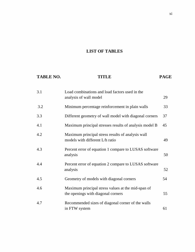
LIST OF TABLES
TABLE NO. TITLE PAGE
3.1 Load combinations and load factors used in the
analysis of wall model 29
3.2 Minimum percentage reinforcement in plain walls 33
3.3 Different geometry of wall model with diagonal corners 37
4.1 Maximum principal stresses results of analysis model B 45
4.2 Maximum principal stress results of analysis wall
models with different L/h ratio 49
4.3 Percent error of equation 1 compare to LUSAS software
analysis 50
4.4 Percent error of equation 2 compare to LUSAS software
analysis 52
4.5 Geometry of models with diagonal corners 54
4.6 Maximum principal stress values at the mid-span of
the openings with diagonal corners 55
4.7 Recommended sizes of diagonal corner of the walls
in FTW system 61
xii
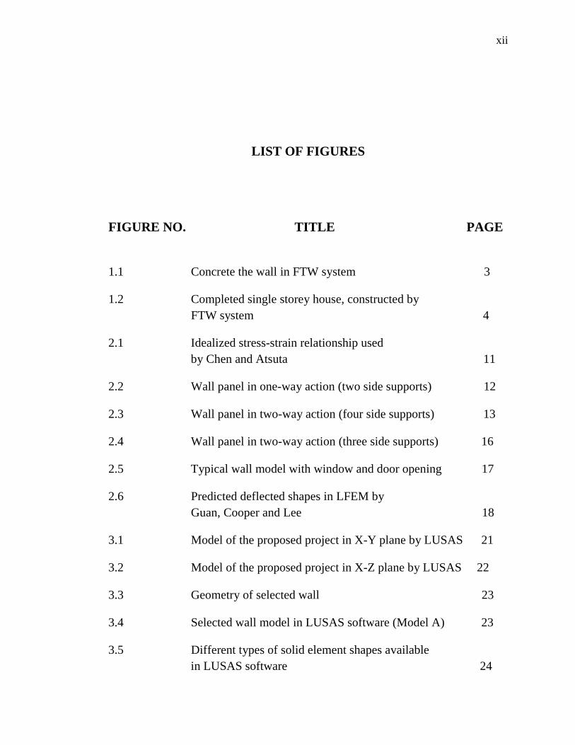
LIST OF FIGURES
FIGURE NO. TITLE PAGE
1.1 Concrete the wall in FTW system 3
1.2 Completed single storey house, constructed by
FTW system 4
2.1 Idealized stress-strain relationship used
by Chen and Atsuta 11
2.2 Wall panel in one-way action (two side supports) 12
2.3 Wall panel in two-way action (four side supports) 13
2.4 Wall panel in two-way action (three side supports) 16
2.5 Typical wall model with window and door opening 17
2.6 Predicted deflected shapes in LFEM by
Guan, Cooper and Lee 18
3.1 Model of the proposed project in X-Y plane by LUSAS 21
3.2 Model of the proposed project in X-Z plane by LUSAS 22
3.3 Geometry of selected wall 23
3.4 Selected wall model in LUSAS software (Model A) 23
3.5 Different types of solid element shapes available
in LUSAS software 24
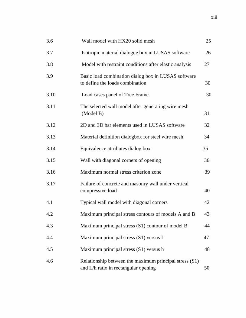
xiii
3.6 Wall model with HX20 solid mesh 25
3.7 Isotropic material dialogue box in LUSAS software 26
3.8 Model with restraint conditions after elastic analysis 27
3.9 Basic load combination dialog box in LUSAS software
to define the loads combination 30
3.10 Load cases panel of Tree Frame 30
3.11 The selected wall model after generating wire mesh
(Model B) 31
3.12 2D and 3D bar elements used in LUSAS software 32
3.13 Material definition dialogbox for steel wire mesh 34
3.14 Equivalence attributes dialog box 35
3.15 Wall with diagonal corners of opening 36
3.16 Maximum normal stress criterion zone 39
3.17 Failure of concrete and masonry wall under vertical
compressive load 40
4.1 Typical wall model with diagonal corners 42
4.2 Maximum principal stress contours of models A and B 43
4.3 Maximum principal stress (S1) contour of model B 44
4.4 Maximum principal stress (S1) versus L 47
4.5 Maximum principal stress (S1) versus h 48
4.6 Relationship between the maximum principal stress (S1)
and L/h ratio in rectangular opening 50
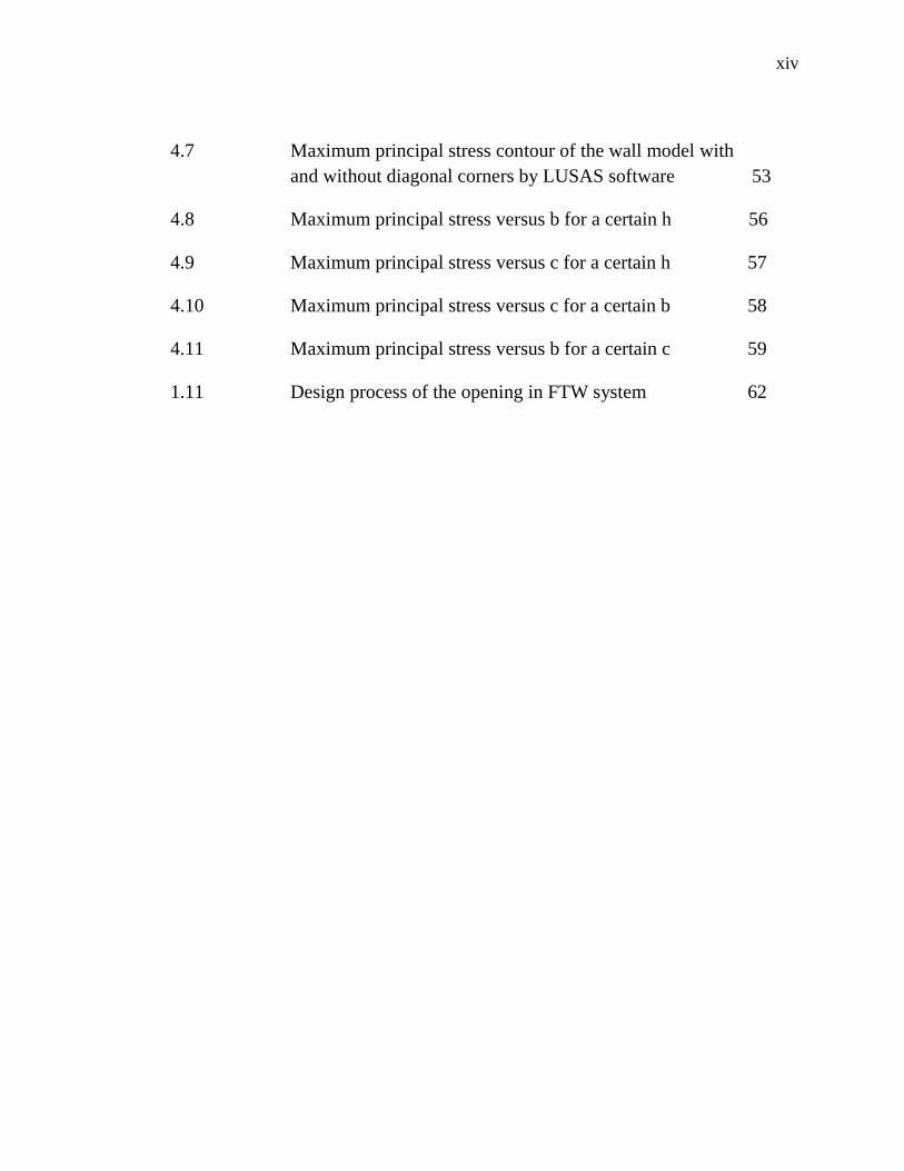
xiv
4.7 Maximum principal stress contour of the wall model with
and without diagonal corners by LUSAS software 53
4.8 Maximum principal stress versus b for a certain h 56
4.9 Maximum principal stress versus c for a certain h 57
4.10 Maximum principal stress versus c for a certain b 58
4.11 Maximum principal stress versus b for a certain c 59
1.11 Design process of the opening in FTW system 62
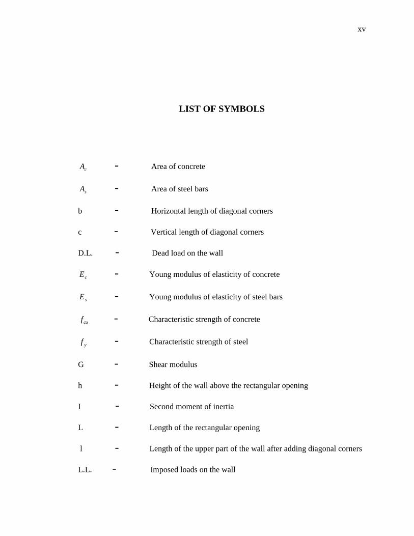
xv
LIST OF SYMBOLS
cA - Area of concrete
sA - Area of steel bars
b - Horizontal length of diagonal corners
c - Vertical length of diagonal corners
D.L. - Dead load on the wall
cE - Young modulus of elasticity of concrete
sE - Young modulus of elasticity of steel bars
cuf - Characteristic strength of concrete
yf - Characteristic strength of steel
G - Shear modulus
h - Height of the wall above the rectangular opening
I - Second moment of inertia
L - Length of the rectangular opening
l - Length of the upper part of the wall after adding diagonal corners
L.L. - Imposed loads on the wall
xvi
M - Moment in the wall
S1 - Maximum principal stress in LUSAS
S2 - Intermediate principal stress in LUSAS
S3 - Minimum principal stress in LUSAS
*
1S - Maximum principal stress at the mid-span of the wall above the
rectangular opening
S.W. - Self weight of the wall
W.L. - Wind load on the wall
- Coefficient of thermal expansion
m - Partial safety factor for strength of materials
1 - Maximum principal stress
2 - Intermediate principal stress
3 - Minimum principal stress
c - Uniaxial compression strength
t - Uniaxial tension strength
x - Normal stress in X direction
y - Normal stress in Y direction
xy -
- Poison’s Ratio
- Ultimate critical load combination on the wall

xvii
LIST OF APPENDICES
APPENDIX TITLE PAGE
A Proposed Plan Details 72
B Loading Calculations for Model A 77
C Metrics Standard Specification 78
1
CHAPTER 1
INTRODUCTION
1.4 Background of Fast-Track Wall (FTW) System
Concrete walls are usually constructed by erecting form panels in parallel
spaced apart and then pouring concrete in the space between the forms. Most common
method of erecting concrete walls involves form panels of plywood and wood forming.
If reinforcement is needed, rebar or other kinds of metal reinforcement is installed in the
space between the forms. In some installations, metal reinforcement is installed prior to
structural forms. After the space is filled with concrete, the wooden forms are removed.
This type of construction method of forming up and pouring concrete wall in-
situ is cumbersome. The wood itself is relatively expensive and provision of wooden
form is labor intensive. Skilled labors are needed to erect the wooden forms and the
wooden forms need to be removed after poured concrete is set. Accordingly, erection
operation for such construction method is time consuming and required considerable
expensive skilled labors for erection. Moreover, a large proposition of form
components or materials is non-reusable after the wooden forms are removed.
Although conventional building methods are well established and are generally
effective for constructing traditional building structure, there is still a need for
2
constructing a building structure which is cost effective to implement and can be
quickly and easily utilized so as to construct a desired building structure.
Fast-Track Wall (FTW) system [1] is an innovative method of construction
which uses the inherent strength of concrete to produce cost effective and durable
structures and generally relates to a formwork system and more particularly relates to a
fast-track forming system for concrete or mortar wall. The normal method of
constructing load-bearing concrete elements is to place the concrete into temporary
formwork or moulds, which are then removed once the concrete has attained sufficient
strength to be self-supporting and avoid damage.
Fast Track Wall system can be used on many types of projects. The idea behind
fast track is to complete the overall project sooner by having portions of construction
and design proceeding simultaneously.
Fast Track Wall system is casting concrete in a reusable mould and then
transport to the construction site that will help to reduce the wastage in the construction
industry by minimizing the conventional usage of timber. It is a formwork/mould
system that helps to revolutionize the Malaysian tradition of constructing a single and
double storey house. The roof structure can be of, for example, beams/trusses
constructed either in horizontal or raked. The beams /trusses give added stability and
strength to the top of building structure, and to support the roof and ceiling materials.
This system has been successfully practiced where the site is difficult to be accessed by
heavy machineries and vehicles.
The fast track project causes the structural engineer to design a building in
reverse of how design is normally done. Structures are usually designed from the top
down. Upper floors are designed first and gravity loads are tabulated from the roof
down to the foundations.
3
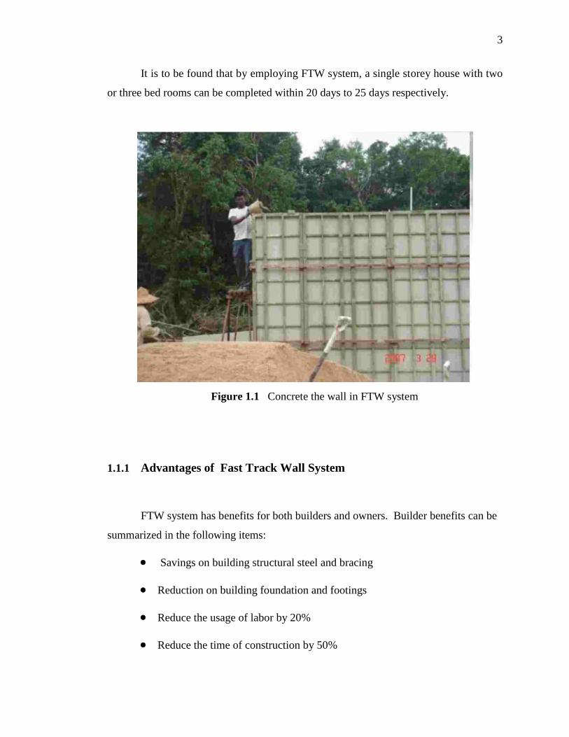
It is to be found that by employing FTW system, a single storey house with two
or three bed rooms can be completed within 20 days to 25 days respectively.
Figure 1.1 Concrete the wall in FTW system
1.1.1 Advantages of Fast Track Wall System
FTW system has benefits for both builders and owners. Builder benefits can be
summarized in the following items:
Savings on building structural steel and bracing
Reduction on building foundation and footings
Reduce the usage of labor by 20%
Reduce the time of construction by 50%
4
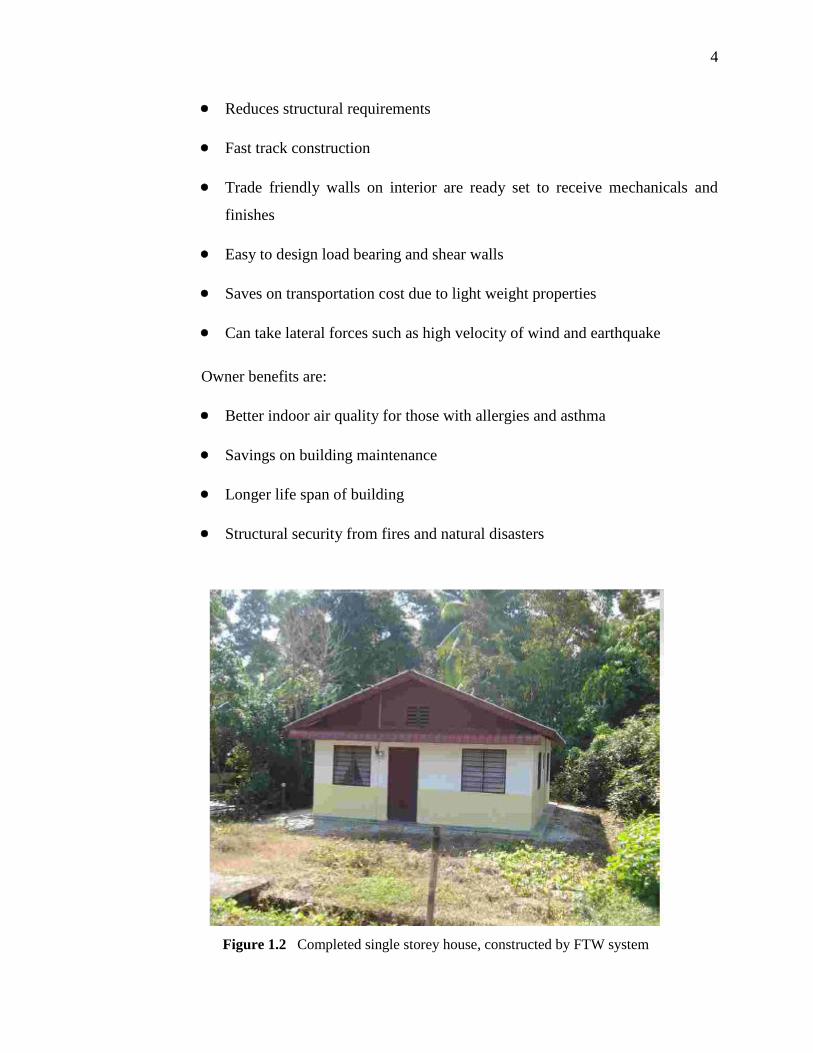
Reduces structural requirements
Fast track construction
Trade friendly walls on interior are ready set to receive mechanicals and
finishes
Easy to design load bearing and shear walls
Saves on transportation cost due to light weight properties
Can take lateral forces such as high velocity of wind and earthquake
Owner benefits are:
Better indoor air quality for those with allergies and asthma
Savings on building maintenance
Longer life span of building
Structural security from fires and natural disasters
Figure 1.2 Completed single storey house, constructed by FTW system
5
1.2 Problem Statement
Large openings in conventional construction require large headers and
supporting posts. On the other hand size of openings and windows in the houses
constructed by FTW system are limited and typically small. By adding large openings,
Fast Track Wall system becomes more and more cost effective because large openings
reduce the materials needed such as concrete, steel mesh, formwork, labor, etc. and
reduce the construction duration.
1.3 Aim and Objectives
The main objectives of this research are:
To study the stress distribution in double storey houses constructed
by Fast-Track Wall (FTW) system
To propose a design procedure based on stress criteria
To define the optimum size of rectangular openings for the walls in Fast-
Track Wall system
To suggest the best haunch dimensions of the openings in the walls of Fast-
Track Wall system
6
1.5 Scope of Study
The scopes of work for this research are as follow:
3D linear elastic analysis of wall system of double storey house made by
Fast-Track Wall system
Modeling of a proposed double storey house, using solid element, by
LUSAS software
Determine the stress distribution in concrete under typical domestic load
cases.
1.5 Expected Findings
The following can be some of the outcomes:
To define critical stress locations based on compression or tension stress
limitations of concrete according to BS 8110
To propose suitable size of rectangular openings in Fast Track Wall system
To suggest a method to design the openings in walls of Fast-Track Wall
system based on stresses limitations.
67
REFERENCES
1. Muhd Zaimi, A. M., Rosli, M. Z., and Group. Fast Track Wall System. Malaysian
Utility Innovation Pending Number: PI 2009 0172. World Intellectual Property
Organization WO/2010/082812 A2. 2009
2. British Standards Institution (BSi). The Structural Use of Concrete. London, BS
8110. 1997
3. Ramli Abdullah. Advanced Reinforced Concrete Structures. Lecturer note,
University Technology Malaysia. 2009
4. Bath, P., Thomas, J. M., and Choo, B. S. Reinforced Concrete: Design Theory and
Examples. 3rd
ed. New York: Taylor and Francis. 2006
5. American Concrete Institution (ACI). Building Code Requirements for Structural
Concrete and Commentary. Detroit, ACI 318. 2005
6. Meinheit, D. F. Discussion on Proposed Revision of ACI 318-363: Building Code
Requirements for Reinforced Concrete. Am. Concr. Inst. 1970. 67(1): 710-722
7. Yokel, F. Y., and Somes, N. F. Discussion on Proposed Revision of ACI 318-363:
Building Code Requirements for Reinforced Concrete. Am. Concr. Inst. 1970.
67(1): 723-736
8. Yokel, F. Y. Stability and Load Capacity of Members with no Tensile Strength.
Struct. Div. Am. Soc. civ. Engrs. 1971. 97(1): 1913-1921
9. Unnirishna Pillai, S., and Parthasarathy, C. V. Ultimate Strength and design of
concrete walls. Building and Environment. 1977. 12(1): 25-29
68
10. Parthasarathy, C. V. Ultimate Strength of Load Bearing Walls. M.Sc. Thesis.
Calicut University; 1973
11. Seddon, A. E. The Strength of Concrete Walls under Axial and Eccentric Loads.
Priceeding of a Symposium on Strength of Concrete Structures. May 1956. London:
Cement and Concrete Association. 1956. 445–486.
12. Varghese, P. C. Advanced Reinforced Concrete Design. 2nd
. ed. New Delhi:
Prentice-Hall of India. 2006
13. Chen, W. F. Discussion of: Stability and Load Capacity of Members with no
Tensile Strength, (F. Y. Yokel). Struct. Div. Am. Soc. civ. Engrs. 1972. 96(1): 1193-
1204
14. Chen, F. W., and Atsuta, T. Strength of Eccentrically Loaded Walls. Int. J. Solids
Structures. 1973. 9(1): 1283-1300
15. Saheb, S. M., and Desayi, P. Ultimate Strength of RC Wall Panels in One-way In-
plane Action. Struct. Eng. ASCE. 1989. 115(10): 2617-2630
16. Fragomeni, S. Design of Normal and High Strength Reinforced Concrete Walls.
Ph.D. Thesis. Griffith University, Melbourne; 1995
17. Doh, J. H. Experimental and Theoretical Studies of Normal and High Strength
Concrete Wall Panels. Ph.D. Thesis. Griffith University, Melbourne; 2002
18. Doh, J. H., and Fragomeni, S. Evaluation of Experimental Work on Concrete Walls
in One and Two-way Action. Aust. J. Struct. Eng. 2005. 6(1): 37-52
19. Swartz, S. E., Rosebraugh, V. H., and Berman, M. Y. Buckling Tests on
Rectangular Concrete Panels. ACI Struct. J. 1974. 71(1): 33-39
20. Saheb , S. M., and Desayi, P. Ultimate Strength of RC Wall Panels in Two-way In-
plane Action. Struct. Eng. ASCE. 1990. 116 (5): 1384-1402
69
21. Sanjayan, J. G., and Maheswaran, T. Load Capacity of Slender High Strength with
Side Supports. ACI Struct. J. 1999. 96(4): 571-576
22. Saheb , S. M., and Desayi, P. Ultimate Strength of RC Wall Panels with Opening.
Struct. Eng. ASCE. 1990. 116 (4): 1565-1578
23. Doh, J. H., and Fragomeni, S. Ultimate Load Formula for Reinforced Concrete
Wall Panels with Opening. Adv. Struct. Eng. 2006. 9(1): 103-115
24. Lee, D. J. Experimental and Theoretical Study of Normal and High Strength
Concrete Wall Panels with Openings. Ph.D. Thesis. Griffith University, Melbourn;
2008
25. Doh, J. H., Lee, D. J., Guan, H., and Loo, Y. C. Concrete Wall With Various
Support Conditions. Proceeding of the 4th
4th International Conference on
Advances in Structural Engineering and Mechanics (ASEM 08). May 26-28, 2008.
Korea: Techno-Press. 2008. 967-975
26. Doh, J. H., Loo, Y. C., and Fragomeni, S. Concrete Wall with and without
Openings Supported on Three Sides. Proceeding of the 21th
Australian Conference
on the Mechanics of Structures and Materials (ACMSM21). Dec 7-10, 2010.
London: Taylor and Francis Group. 2011. 209-214
27. Rombach, G. A. Finite Element Design of Concrete Structures. Heron Quay,
London: Tomas Telford Publishing. 2004
28. Guan, H. and Loo, Y. C. Flexural and Shear Failure Analysis of Reinforced
Concrete Slabs and Flat Plates. Adv. Struct. Eng. 1997. 1(1): 71-76
29. Hallinan, P., and Guan, H. Layered Finite Element Analysis of One-way and Two-
way Concrete Walls with Openings. Adv. Struct. Eng. 2007. 10(1): 55-72
70
30. Hallinan, P., and Guan, H. Parametric Study on Slenderness Ratio of Concrete
Walls with Openings. Proceeding of the Australian Structural Engineering
Conference. September 11-14, 2005. Newcastle, Australia: Engineers Australia.
2005. 578-587
31. Hallinan, P., and Guan, H. A Numerical Study of One-way and Two-way Concrete
Walls with Openings. Proceedings of the 10th
International Conference on Civil,
Structural and Environmental Engineering Computing. August 30-September 2,
2005. Stirling, Scotland: Civil-Comp Press. 2005. 174
32. Ghobarah, A. and Youssef, M. Modelling of Reinforced Concrete Structural Walls.
Eng. Struct. 1999. 21(1): 912-923
33. Thomson, E. D., Perdomo, M. E., Picn, R., Marante, M. E., and Firez, L. J.
Simplified Model for Damage in Squat RC Shear Walls. Eng. Struct. 2009. 31(1):
2215-2223
34. Guan, H., Cooper, C., and Lee, D. J. Ultimate Strength Analysis of Normal and
High Strength Concrete Wall Panels with Varying Opening Configurations.
Engineering Structures. 2010. 32(5): 1341-1355
35. LUSAS Mdeller User Manual Version 14. [CD-ROM]. Kingston Upon Thames
Surray. 2006
36. British Standards Institution (BSi). Loading for Building. London, BS 6399. 1996
37. Sundaraj, G. Wind Data Validation and Determination of Basic Wind Speed for
Building in Malaysia. M.Sc. Thesis. University Sains Malaysia; 2002
38. Husain, N. M., Zaini, S. S., and Majid, T. A. Development of Terrain Height
Multiplier for Seberang Jaya, Suburban Area. Proceeding of the International
Conference on Construction and Building Technology 2008 (ICCBT 2008). Kuala
Lumpur. June 16-20, 2008. 221-224

71
39. British Standards Institution (BSi). Steel, concrete and composite bridges. London,
BS 5400-3. 2000
40. Redzuan Abdullah. Finite Element Method for Structural Analysis. Lecturer note,
University Technology Malaysia. 2010
41. Ugural, A. C. Stresses in Plates and Shells. 2nd
ed. New York: McGraw-Hill. 1998