finite element method in fracture mechanicsimechanica.org/files/termpaper.pdf · the university of...
TRANSCRIPT

THE UNIVERSITY OF TEXAS AT AUSTIN
Finite Element Method
in Fracture Mechanics
Naoto Sakakibara
5/9/2008

2
Table of Contents
Summary............................................................................................................................................ 3
Introduction ....................................................................................................................................... 3
Quarter Point Element ...................................................................................................................... 4
Transition element ............................................................................................................................ 5
Meshing Rules for QPE and transitional element ............................................................................. 6
Stress Intensity Factor (SIF) ............................................................................................................... 8
Enriched Element ............................................................................................................................ 10
NS‐F‐FEM ver1.0 .............................................................................................................................. 12
Introduction to Extended Finite Element Method .......................................................................... 14
Adding Singularity field .................................................................................................................... 14
Adding Discontinuity ....................................................................................................................... 14
Enriching Mesh ................................................................................................................................ 15
Conclusion ....................................................................................................................................... 16
Bibliography ..................................................................................................................................... 17

3
Summary
The Finite Element Method (FEM) has been one of the most powerful numerical tools for the
solution of the crack problem in fracture mechanics. In 1960s, you can find the early application
of the finite element method in the papers by Swedlow, Williams and Yang [1965]. Henshell and
Shaw [1975] and Barsoum [1976] suggested the quarter point element in order to get accurate
solution around crack tip in 1975. On the other hand, Blenzley [1974] developed the enriched
elements in 1974. In recent research, Extended Finite Element Method (XFEM), which allows you
to calculate the crack propagation without remeshing finite elements, is proposed at the end of
20th century.
Introduction
It is known that the solution of the finite element has some error (5 to 10 %) with the general
isoparametric element. In addition to that, it is also reported that the large number of the mesh
don’t guarantee the solutions in the vicinity of the crack tip. The reason of those inaccurate
solutions is caused by the singularity of the stress (strain) field around crack tip as shown below.
(Mode I crack tip field from LEFM)
σ3C√r
cosθ2
1 sinθ2
σ3C√r
cosθ2
σ3C√r
sinθ2cos
θ2
Due to the lower order of the shape function of the isoparametric elements; those singularity
variation is hardly obtained. In this paper, two outstanding techniques will be introduced. Both
techniques can achieve the singularity field around the crack tip. One is called Collapsed
Quadrilateral Quarter element and the other is enriched elements.
4
Quarter Point Element
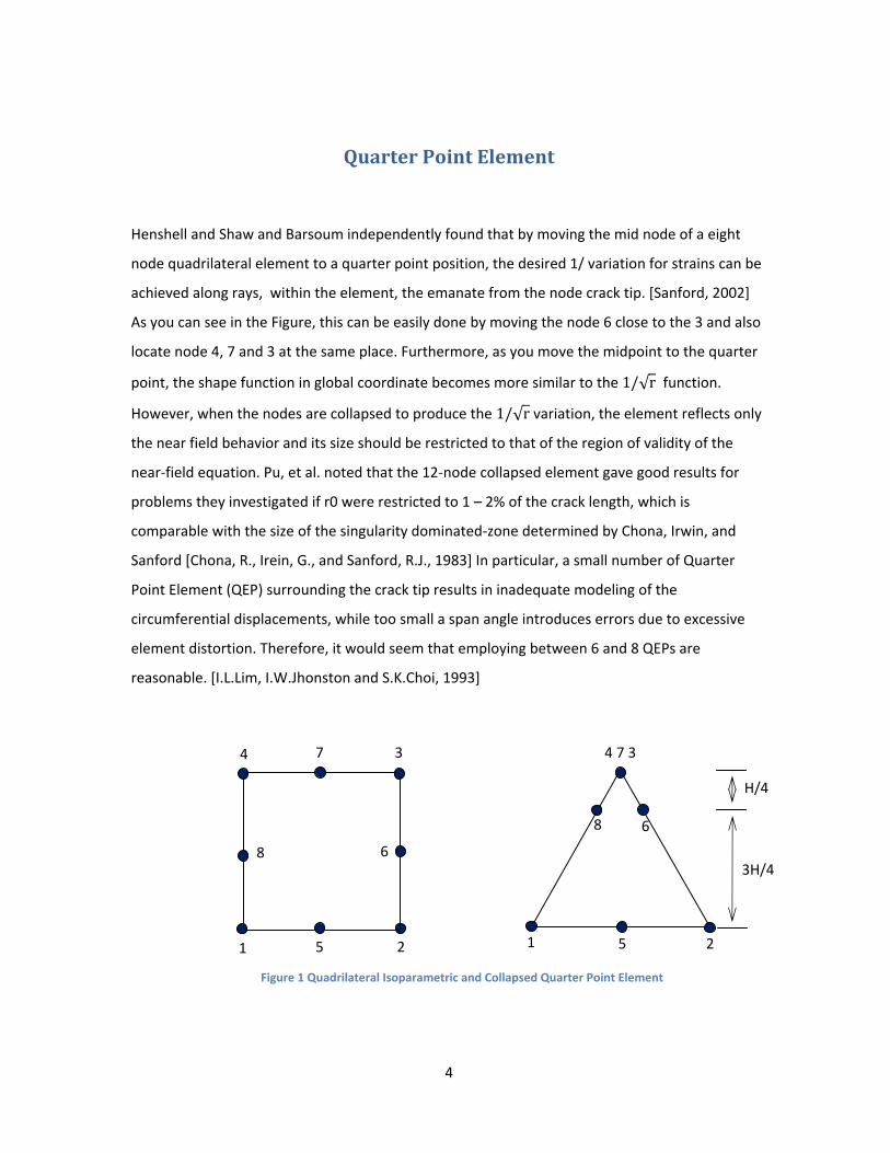
Henshell and Shaw and Barsoum independently found that by moving the mid node of a eight
node quadrilateral element to a quarter point position, the desired 1/ variation for strains can be
achieved along rays, within the element, the emanate from the node crack tip. [Sanford, 2002]
As you can see in the Figure, this can be easily done by moving the node 6 close to the 3 and also
locate node 4, 7 and 3 at the same place. Furthermore, as you move the midpoint to the quarter
point, the shape function in global coordinate becomes more similar to the 1/√r function.
However, when the nodes are collapsed to produce the 1/√r variation, the element reflects only
the near field behavior and its size should be restricted to that of the region of validity of the
near‐field equation. Pu, et al. noted that the 12‐node collapsed element gave good results for
problems they investigated if r0 were restricted to 1 – 2% of the crack length, which is
comparable with the size of the singularity dominated‐zone determined by Chona, Irwin, and
Sanford [Chona, R., Irein, G., and Sanford, R.J., 1983] In particular, a small number of Quarter
Point Element (QEP) surrounding the crack tip results in inadequate modeling of the
circumferential displacements, while too small a span angle introduces errors due to excessive
element distortion. Therefore, it would seem that employing between 6 and 8 QEPs are
reasonable. [I.L.Lim, I.W.Jhonston and S.K.Choi, 1993]
4
1 5
6
3
2
7
8
1 5 2
8 6
4 7 3
H/4
3H/4
Figure 1 Quadrilateral Isoparametric and Collapsed Quarter Point Element

5
Figure 2 Image of Shape Function
Even though quarter point elements have some difficulty in meshing, there is a strong advantage
of capability of using general Finite Element Code. In other words, there is no need to change the
formulation of finite element. Both nodes are simply expressed as below.
u x N x u
Transition element
Under special configuration, transitional elements improve the accuracy of stress intensity factor
computations. These transitional elements are located in the immediate vicinity of the singular
elements with the mid‐side nodes so adjusted as to reflect or extrapolate the square root
singularity on the stress and strains at the tip of the crack. As shown in the equation, the mid‐
point of the transitional element can be obtained by this relation. In this formula, the length of
the collapsed QPE is defined as 1 and L is the Length from crack tip to the outside of the
transitional elements.
βL L 2√L 1
4

6
According to the M.A.Hussain, it was found that there was improvement in accuracy for a
configuration which consisted only singular and transitional elements, when transitional
elements are used for a double‐edge crack problem.
Figure 3 Transition Element
Meshing Rules for QPE and transitional element
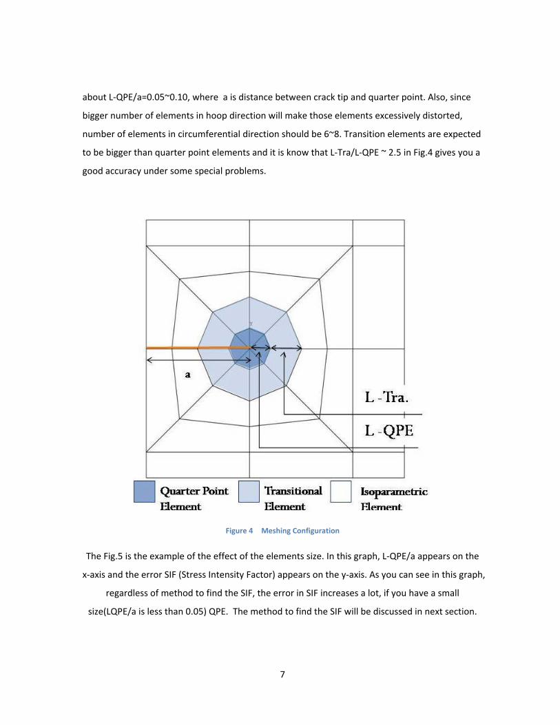
Fig.4 is the example of the meshing for the crack tip problem. As you can see in the figure, a plate
with certain crack size is given. Quarter point elements are located around the crack tip so that
the singularity of the stress & strain field will be satisfied. Transitional elements are deployed
right next to the quarter point element. Finally, rest of the region of the plate is meshed by the
CPE8 elements.
In general, there is no optimal numbers for the size of the each element. The mesh size should be
determined in each problem so that good accuracy is obtained. However, there exist some
suggestions in order to define the size of the mesh. For the collapsed quadrilateral QPE, the
recommended ratio for the crack length and the distance between crack tip and quarter point is
7
about L‐QPE/a=0.05~0.10, where a is distance between crack tip and quarter point. Also, since
bigger number of elements in hoop direction will make those elements excessively distorted,
number of elements in circumferential direction should be 6~8. Transition elements are expected
to be bigger than quarter point elements and it is know that L‐Tra/L‐QPE ~ 2.5 in Fig.4 gives you a
good accuracy under some special problems.
Figure 4 Meshing Configuration
The Fig.5 is the example of the effect of the elements size. In this graph, L‐QPE/a appears on the
x‐axis and the error SIF (Stress Intensity Factor) appears on the y‐axis. As you can see in this graph,
regardless of method to find the SIF, the error in SIF increases a lot, if you have a small
size(LQPE/a is less than 0.05) QPE. The method to find the SIF will be discussed in next section.

8
Figure 5 Stress Intensity Factor vs QPE size
Stress Intensity Factor (SIF)
(a) Quarter‐point displacement technique
The quarter‐point displacement technique (QPDT) was applied in the FEM simulation to evaluate
the SIF.
K 2 Gκ 1
√2 πL
vB vD
K 2 Gκ 1
√2 πL
uB uD

where
κ = (3
L = le
u’, v’
(b
Simila
show
Amon
e,
– ν)/ (1+ ν) f
ength of QPE
= local displa
b) Displacem
ar to the QPD
n below.
ng these tech
for plane stres
along clack f
acement arou
ment correlatio
DT method, SI
niques, the D
ss, = 3 - 4 ν fo
face,
und crack as s
on technique
F will be foun
DCT is more w
Figure 6 No
E
C
9
or plane strain
showed in Fig
nd by the Disp
widely used, a
ode # for SIF calc
D
B
n and axisym
g.
placement co
lthough the Q
culation
mmetry,
orrelation tech
QPDT is simpl
hnique as
ly to implemeent.
10
Enriched Element
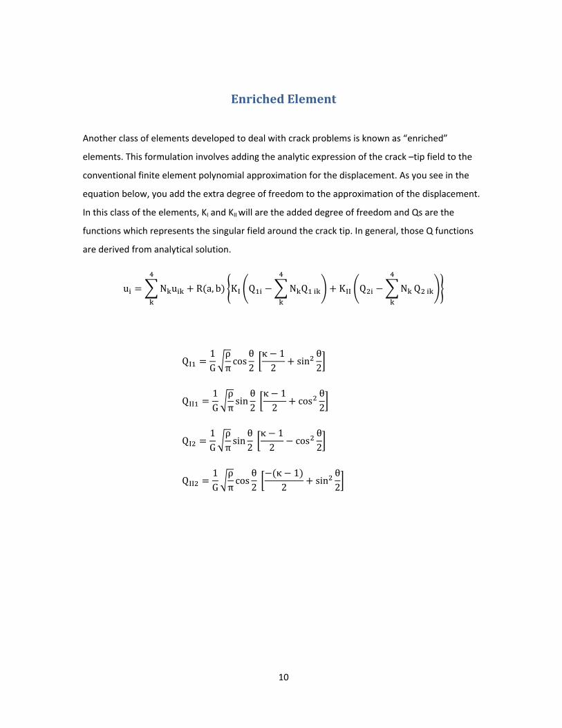
Another class of elements developed to deal with crack problems is known as “enriched”
elements. This formulation involves adding the analytic expression of the crack –tip field to the
conventional finite element polynomial approximation for the displacement. As you see in the
equation below, you add the extra degree of freedom to the approximation of the displacement.
In this class of the elements, KI and KII will are the added degree of freedom and Qs are the
functions which represents the singular field around the crack tip. In general, those Q functions
are derived from analytical solution.
u N u R a, b KI Q N Q KII Q N Q
QI1G
ρπcos
θ2 κ 12
sinθ2
QII1G
ρπsin
θ2 κ 12
cosθ2
QI1G
ρπsin
θ2 κ 12
cosθ2
QII1G
ρπcos
θ2
κ 12
sinθ2

This F
is the
Basica
soluti
It is kn
this is
1974]
Fig.7 shows th
experimenta
ally, he has fo
on from sma
nown that en
s true, only if
] used 7 x 7 G
he result from
al data of nor
ound that for
ll crack size to
nriched eleme
you use the a
aussian quad
Figure 7 S
m Blenzy’s pap
malized SIF a
this type of p
o relatively b
ents can achie
appropriate in
drature in ord
11
Stress Intensity F
per [Benzly, 1
nd circles are
problem, enri
ig clack.
eve singular f
ntegration m
der to achieve
Factor
1974] with sid
e his Finite Ele
ched elemen
field around c
ethod. For ex
e this higher o
de cracked pa
ement Analys
nt method has
crack tip very
xample, Blenz
order function
anel. Solid line
sis data.
s accurate
well. Howev
zy [Benzly,
ns.
e
ver
12
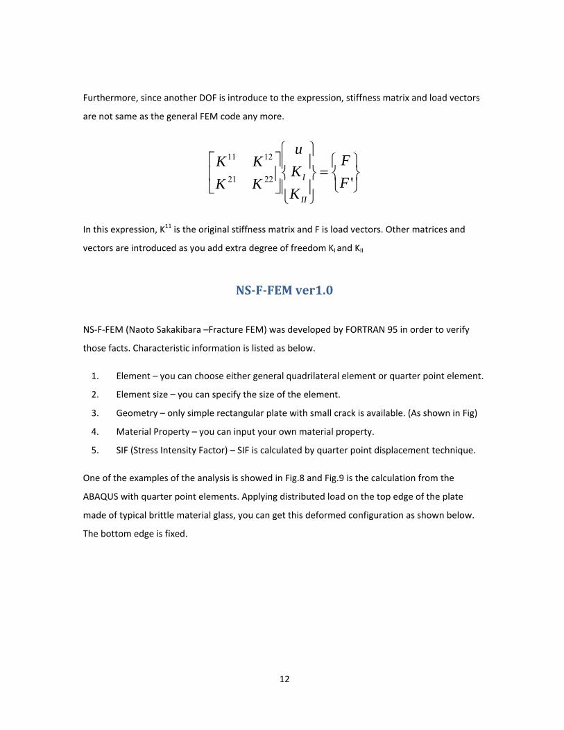
Furthermore, since another DOF is introduce to the expression, stiffness matrix and load vectors
are not same as the general FEM code any more.
⎭⎬⎫
⎩⎨⎧
=⎪⎭
⎪⎬
⎫
⎪⎩
⎪⎨
⎧
⎥⎦
⎤⎢⎣
⎡'2221
1211
FF
KKu
KKKK
II
I
In this expression, K11 is the original stiffness matrix and F is load vectors. Other matrices and
vectors are introduced as you add extra degree of freedom KI and KII
NSFFEM ver1.0
NS‐F‐FEM (Naoto Sakakibara –Fracture FEM) was developed by FORTRAN 95 in order to verify
those facts. Characteristic information is listed as below.
1. Element – you can choose either general quadrilateral element or quarter point element.
2. Element size – you can specify the size of the element.
3. Geometry – only simple rectangular plate with small crack is available. (As shown in Fig)
4. Material Property – you can input your own material property.
5. SIF (Stress Intensity Factor) – SIF is calculated by quarter point displacement technique.
One of the examples of the analysis is showed in Fig.8 and Fig.9 is the calculation from the
ABAQUS with quarter point elements. Applying distributed load on the top edge of the plate
made of typical brittle material glass, you can get this deformed configuration as shown below.
The bottom edge is fixed.

13
Figure 8 Deformed Configuration of NSFEM
Figure 9 Deformed Configuration of ABAQUS

14
Introduction to Extended Finite Element Method
At the end of the 20th century, new finite element method called Extended FEM was introduced.
This is the new FEM technique mainly for the fracture mechanics. The advantage of this
technique is that mesh is independent from the crack geometry, while in the most of the FEM
application, mesh should be created along the crack geometry. However, XFEM doesn’t need to
consider the crack geometry when it is created. This technique first introduced by Belytschko
et.al. in their paper. [Nicolas Moes, John Dolbow and Ted Belytschko, 1999] In this section, two
main concept of XFEM is explained. Both of them are enriching technique by using special
function and adding extra degree of freedom. One of them is adding singular expression and the
other is adding discontinuous expression which allows the element to have two different strain
and stress field. The equation below is general XFEM expression. First term is represent general
FEM approximation of the displacement field and 2nd term applies singular field around crack tip.
Finally, 3rd term gives discontinuity to the elements.
Adding Singularity field As well as the enriched element explained in this paper before, the basic concept is adding
singularity field so that FEM displacement approximation achieve singular field around crack tip.
As you can see in the Fig. normally this enrichment is applied at the element including crack tip.
Adding Discontinuity By applying the discontinuity to the element, we can express two different strain fields in one
element. This means that the strain expression in one side of crack is different from the other
side of crack. In this Fig.10, region I and II is in a same element but different fields due to the
discontinuous function. Also, two dashed line in the picture is assumed two crack edge.
∑ ∑∑ ∑= == =
++=n
j
n
hhh
mt
k
mf
lklkj HNFNuNu
j1 11 1
))(()())()(()()( axxbxxxx ξ

As shodisconlocateat the
own in previontinuity. Theed at the crace crack exist li
Figure
ous section, ine way to enricck tip and enrike Fig.11
10 Enriched ele
Enrin XFEM elemeching the elemriched by the
15
ement with disco
ching Meents are enricment is showndiscontinuou
ontinuous funct
sh ched by addinn below. Singus property el
tion
ng singular fiegular elementlement shoul
eld and t should be d be deployed

Con
In this
point
eleme
the el
size. B
the re
geom
appro
clusion
s paper, three
element. The
ent approxim
lement by de
Both two was
esearch. XFEM
metry. Mesh is
opriate eleme
F
e FEM techniq
e benefit of th
ation; theref
rived functio
s introduce ab
M enables you
s independen
ent in right wa
Figure 11 Enrich
ques for fract
his element is
ore this meth
n in analytica
bout 1970’s a
u to analyze t
t from the cra
ay.
16
ed element aro
ture mechani
s you can use
hod is relative
al calculation.
and nowadays
the crack pro
ack geometry
und crack tip
ics were intro
e general shap
ely easy to us
This is not st
s new techniq
blem without
y. All you nee
oduced. First o
pe function fo
e. Second on
trongly depen
que called XF
t considering
d to worry is
one is quarte
or finite
e is enriching
ndent on mes
EM is under
the crack
to enrich
er
g
sh

17
Bibliography
Barsoum, R. (1976). Furthur application of quadratic isoparametric elements to linear fracture mechanics of plate bending and general shells. Int.J.Num.Meth,Engng , 11,167‐169.
Benzly, S. (1974). Representation of of singularities with isoparametric finite elements. Int.J.Num.Meth.Engng. , 8,537‐545.
Chona, R., Irein, G., and Sanford, R.J. (1983). The influence of specimen size and shape on the singurarity‐dominated zone. Proceedings, 14th National Symposium on Fracture Mechanics, STP791, Vol.1, American Soc. for Testing and Materials, (pp. I1‐I23). Philadelphia.
Henshell,R.D and Shaw,K.G. (1975). Crack tip finite elements are unnnecessary. Int.J.Num.Meth.Engng. , 9,495‐507.
I.L.Lim, I.W.Jhonston and S.K.Choi. (1993). Application of singular quadratic distorted isoparametric elements in linear fracture mechanics. International journal for numerical methods in engineering , Vol.36, 2473‐2499.
I.L.Lim, I.W.Johnston and S.K.Choi. (1992). On stress intensity factor computation from the quater‐point element displacements. Communications in applied numerical methods , Vol.8, 291‐300.
Mohammad, S. (2008). Extendet finite element. Blackwell Publishing.
Nicolas Moes, John Dolbow and Ted Belystschko. (1999). A finite element method for crack growth withiout remeshing. International jounarl for numerical methods in engineering , 131‐150.
Nicolas Moes, John Dolbow and Ted Belytschko. (1999). A finite element method for crack growth without remshing. Int. J. Nume. Engng , 46, 131‐150.
Sanford, R. (2002). Principle of Fracture Mechanics. Upper Saddle River, NJ 07458: Pearson Education, Inc.
Swedlow,J.,L., Williams,M.L. and Yang,W.H. (1965). Elasto‐plastic Stresses and strains in cracked plate. . Proc.1st.Int.Conf. Fracture.,, (pp. Vol 1, 259‐282). Sendai, Japan.
Figure 1 Quadrilateral Isoparametric and Collapsed Quarter Point Element 4 Figure 2 Image of Shape Function 5

18
Figure 3 Transition Element 6 Figure 4 Meshing Configuration 7 Figure 5 Stress Intensity Factor vs QPE size 8 Figure 6 Node # for SIF calculation 9 Figure 7 Stress Intensity Factor 11 Figure 8 Deformed Configuration of NSFEM 13 Figure 9 Deformed Configuration of ABAQUS 13 Figure 10 Enriched element with discontinuous function 15 Figure 11 Enriched element around crack tip 16