fire detection systems - · pdf filefire detection systems 1 this pocket design &...
TRANSCRIPT
Pocket Design & Installation Guidein association with Gent by Honeywell
Fire Detection Systems
F I R E D E T E C T I O N S Y S T E M S
1This Pocket Design & Installation booklet provides a simple guide for the provision of a fire detection and alarm system in accordance with the recommendations detailed within the British Standard Code of Practice BS5839-1:2002+A2:2008
The handbook is designed to act as an aide-memoire and there is no substitute for reading the full standard, copies of which can be obtained from:
British Standards Institute 389 Chiswick High Road, Chiswick, London W4 4AL
Tel: 020 8996 9001 Web: www.bsi-global.com Email: [email protected]
Contents4 Introduction4 Legal elements 3 Regulatory Reform Fire Safety Order 2005 3 The Equality Act 2010 (formerly the Disability Discrimination Act 1995) 3 Building Regulations Approved Document Part B and Approved Document Part M
4 System Design 3 Outline responsibilities of the Designer 3 Stage 1 Talk to the interested parties to decide on the level of protection or category and agree variations 3 Stage 2 Detection & alarm zones 3 Stage 3 Siting of manual call points 3 Stage 4 Selection and siting of sensors 3 Reduce the risk of false alarms with the Gent sensor application guide 3 Stage 5 Choice and siting of alarm sounders and visual alarms 3 Stage 6 Control equipment & power supplies4 Installation & Wiring 3 Outline responsibilities of the Installer 3 Types of cable and where to use them 3 Other aspects in regard to installation practice 3 Recommendations for mains power supplies 3 Inspection & testing of wiring
4 Commissioning 3 Outline responsibilities of the Commissioning Engineer 3 Identifying additional Variations or ‘snags’ 3 Cause & Effect Matrix 3 Final documentation
4 Best Practice Tips

3 Regulatory Reform Fire Safety Order 2005
3 The Equality Act 2010 (formerly the Disability Discrimination Act 1995)
3 Building Regulation Approved Document Part B
3 Building Regulation Approved Document Part M
All these documents in some way affect what is included in the system. However the Owner/Occupier is ultimately responsible for the level of protection provided.
It is recommended that the Owner/Occupier carries out a Fire Risk Assessment to identify the level of protection required i.e. one of the categories detailed within BS5839-1:2002+A2:2008 ( L1,L2,L3,L4,L5,M,P1 or P2 )
The full responsibilities of the Owner/Occupier are detailed within the new Regulatory Reform Fire Safety Order (RRO) that replaced the majority of existing laws within the UK from Oct 2006.
This guide, due to its size, provides a basic overview to anyone involved in the design or action of a fire detection system. It will identify the current legislative requirements as well as clarify the responsibilities placed on the three key roles involved with the provision of a new system, namely the Designer, Installer and Commissioning Engineer, as well as remind the End User or Owner/Occupier what part they play in ensuring that the best possible system is supplied to protect life and property from fire.
It is important that everyone involved is conversant with the current British Standard Codes of Practice BS5839-1:2002+A2:2008 for general buildings and BS 5839-6:2004 for dwellings including those of multiple occupancy. The Installer should also be conversant with the British Standard relating to general wiring BS 7671.
The guide, which has been prepared by Gent, one of the UK’s largest manufacturers of fire detection systems, is intended to offer practical advice and is not a substitute for any of the standards or legislation referred to.
Legal elements
F I R E D E T E C T I O N S Y S T E M S
Introduction
2
3
Any design should be prepared by a competent individual/organisation, who has consulted all interested parties and created a set of drawings, a specification, a cause & effect or fire plan, a list of Variations and completed a G1 Design certificate, detailed within BS5839-1:2002+A2:2008.
If designs are undertaken without this research being carried out, the fire detection system is unlikely to comply with the legal requirements. This could result in prosecution of the parties involved, particularly those within the supply chain as well as the Owner/Occupier.
WARNING: Anyone who takes on the responsibility for design will do so at their own risk and design liability insurance is advisable.
The Designer’s responsibilities:3 Agree the level of protection or category with Owner/Occupier 3 Justify any Variations and document reasons3 Detail the detection & alarm zones3 Prepare specification and drawings including; 3 Siting of manual call points 3 Siting of point type heat and smoke detectors 3 Siting of beam detectors 3 Siting of any other forms of detection3 Specify type of cable for each circuit3 Specify type of system and equipment3 Include detail for on/off site links with other equipment3 Take into account the risk of false alarms – use the Gent ‘pull out’ application guide at the back of this booklet3 Allow for correct level of sounders and visual alarms3 Prepare a fire plan or cause and effect chart3 Sign a G1 design certificate
Note BS5839-1:2002+A2:2008 recommends that a fire detection system is designed by a competent person, who takes responsibility for completing the design and signing off a ‘Design certificate’ G1. This should not be confused with other certificates relating to Installation G2 and Commissioning G3, that are completed by the parties responsible for those parts.
Also if the contract allows, it is suggested that the Designer witness tests the completed system to ensure the original design is still appropriate – the Design certificate can then be completed after any amendments are included.
System Design
F I R E D E T E C T I O N S Y S T E M S
4
Talk to the interested parties to decide on the level of protection or category and agree Variations
The importance of pre-design planning cannot be overstated. Many parties are likely to have an interest in what the fire detection is expected to do. Ultimately it is up to the Owner/ Occupier, who is responsible by law, to make the final decision on the level of protection provided for a particular building.
In most circumstances the Owner/Occupier will appoint a competent Designer to carry out this work and take liability for the design as a whole.
The nominated Designer is expected to consult the following organisations:
3 The User or Facilities Manager
3 The Building Control Officer
3 The Health and Safety Executive
3 The Insurer
3 The local Fire and Rescue Service
3 A specialist fire alarm system supplier
Issues to be covered by the Designer should include:3 The Fire Risk Assessment demands
3 The requirements necessary to comply with the Regulatory Reform (Fire Safety) Order (RRO) 2005, the Equality Act 2010 (formerly the Disability Discrimination Act 1995) and Building Regulations Approved Documents Part B and Part M
3 The prime purpose of the system (Property or life protection or both)
3 The level of protection suggested by the interested parties. (Category P1or P2, M or L1 L2 L3 L4 or L5)
3 The list of Variations identified by the interested parties
Design Stage 1
F I R E D E T E C T I O N S Y S T E M S
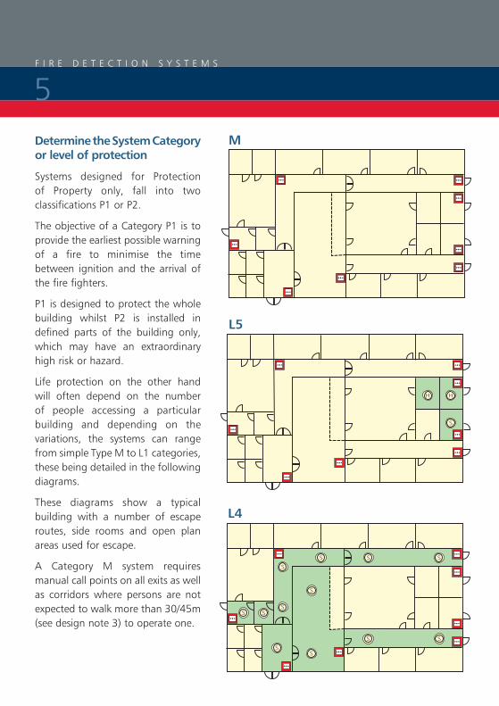
Determine the System Category or level of protection
Systems designed for Protection of Property only, fall into two classifications P1 or P2.
The objective of a Category P1 is to provide the earliest possible warning of a fire to minimise the time between ignition and the arrival of the fire fighters.
P1 is designed to protect the whole building whilst P2 is installed in defined parts of the building only, which may have an extraordinary high risk or hazard.
Life protection on the other hand will often depend on the number of people accessing a particular building and depending on the variations, the systems can range from simple Type M to L1 categories, these being detailed in the following diagrams.
These diagrams show a typical building with a number of escape routes, side rooms and open plan areas used for escape.
A Category M system requires manual call points on all exits as well as corridors where persons are not expected to walk more than 30/45m (see design note 3) to operate one.
L5
M
L4
F I R E D E T E C T I O N S Y S T E M S
5
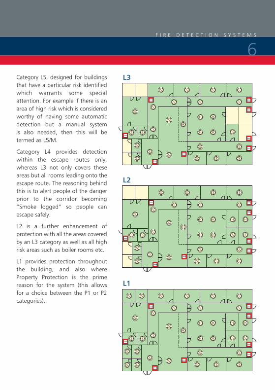
Category L5, designed for buildings that have a particular risk identified which warrants some special attention. For example if there is an area of high risk which is considered worthy of having some automatic detection but a manual system is also needed, then this will be termed as L5/M.
Category L4 provides detection within the escape routes only, whereas L3 not only covers these areas but all rooms leading onto the escape route. The reasoning behind this is to alert people of the danger prior to the corridor becoming “Smoke logged” so people can escape safely.
L2 is a further enhancement of protection with all the areas covered by an L3 category as well as all high risk areas such as boiler rooms etc.
L1 provides protection throughout the building, and also where Property Protection is the prime reason for the system (this allows for a choice between the P1 or P2 categories).
L3
L2
L1
F I R E D E T E C T I O N S Y S T E M S
6
Detection and Alarm Zones
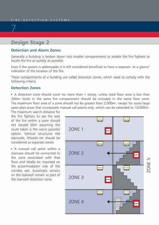
Generally a building is broken down into smaller compartments to enable the fire fighters to locate the fire as quickly as possible.
Even if the system is addressable it is still considered beneficial to have a separate ‘at a glance’ indication of the location of the fire.
These compartments of a building are called detection zones, which need to comply with the following criteria.
Detection Zones
3 A detection zone should cover no more than 1 storey, unless total floor area is less than 300m2. Voids in the same fire compartment should be included in the same floor zone. The maximum floor area of a zone should not be greater than 2,000m2, except for some large open plan areas that incorporate manual call points only, which can be extended to 10,000m2. The maximum search distance for the fire fighters to see the seat of the fire within a zone should not exceed 60m assuming the route taken is the worst possible option. Vertical structures like stairwells, liftwells etc should be considered as separate zones.
3 A manual call point within a staircase should be connected to the zone associated with that floor and ideally be mounted on the accommodation side of the corridor exit. Automatic sensors on the stairwell remain as part of the stairwell detection zone.
ZON
E 5
ZONE 1
ZONE 2
ZONE 3
ZONE 4
Design Stage 2
F I R E D E T E C T I O N S Y S T E M S
7

Siting of Manual Call Points
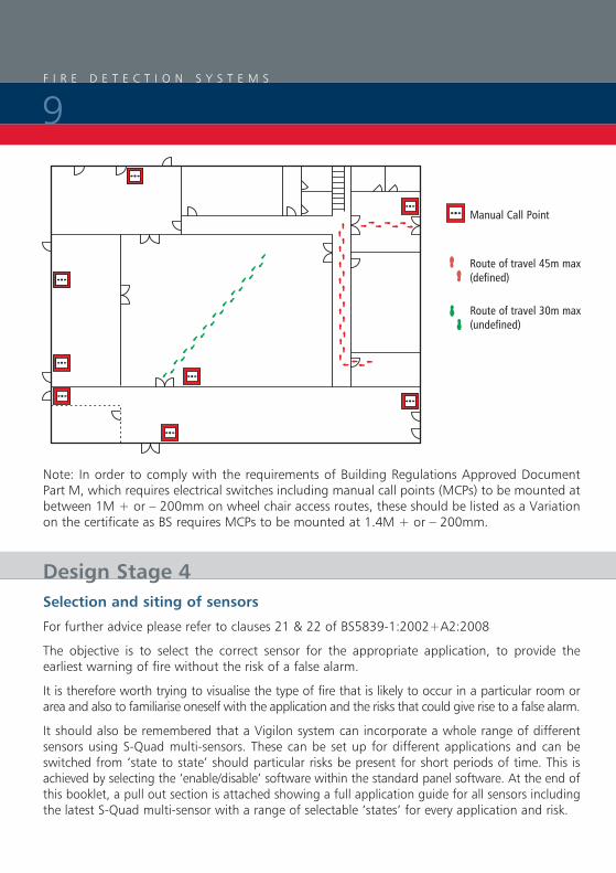
All manual call points, whatever the system, should comply to BS EN54-11 single action Type A version only and should be located as follows:3 On all storey exits and all exits to open air irrespective of whether they are designated fire exits3 Nobody should travel more than 45 metres to reach one, except if the exit routes are undefined in which case the direct line distance should not exceed 30 metres3 The above distances to be reduced to 25 and 16 metres respectively, if there are persons with limited mobility or there is a likelihood of rapid fire development3 In all areas with potential high fire risk such as kitchens etc3 Where phased evacuation is planned, call points will need to be sited on all exits from a particular zone 3 1.4 metres + or – 200mm above the floor3 Call points fitted with protective hinged covers for whatever reason should be listed as a variation
Alarm Zones
An alarm zone is clearly defined within the standard but generally is an area of the building coinciding with the fire compartment boundaries. There must be a clear break between these alarm zones to ensure alert and evacuation messages are not overheard from adjacent areas.
The only other criteria is that an alarm zone may consist of a number of detection zones but not visa versa.
Alarm zones are only required when phased or staged evacuation is required. It is therefore important that care should be taken to ensure only one message is heard at any one time particularly where two alarm zones are attached.
DETECTIONZONE 1
DETECTIONZONE 2
DETECTIONZONE 3
DETECTIONZONE 4
DETECTIONZONE 5
DETECTIONZONE 6
DETECTIONZONE 7
DETECTIONZONE 8
DETECTIONZONE 9
DETECTIONZONE 10
DETECTIONZONE 11
DETECTIONZONE 12
ALA
RMZO
NE
1A
LARM
ZON
E 2
ALA
RMZO
NE
3A
LARM
ZON
E 4
Design Stage 3
F I R E D E T E C T I O N S Y S T E M S
8
Selection and siting of sensors
For further advice please refer to clauses 21 & 22 of BS5839-1:2002+A2:2008
The objective is to select the correct sensor for the appropriate application, to provide the earliest warning of fire without the risk of a false alarm.
It is therefore worth trying to visualise the type of fire that is likely to occur in a particular room or area and also to familiarise oneself with the application and the risks that could give rise to a false alarm.
It should also be remembered that a Vigilon system can incorporate a whole range of different sensors using S-Quad multi-sensors. These can be set up for different applications and can be switched from ‘state to state’ should particular risks be present for short periods of time. This is achieved by selecting the ‘enable/disable’ software within the standard panel software. At the end of this booklet, a pull out section is attached showing a full application guide for all sensors including the latest S-Quad multi-sensor with a range of selectable ‘states’ for every application and risk.
S
H
B
S
H
B
S
H
B
Manual Call Point
Route of travel 45m max(defined)
Route of travel 30m max(undefined)
Design Stage 4
Note: In order to comply with the requirements of Building Regulations Approved Document Part M, which requires electrical switches including manual call points (MCPs) to be mounted at between 1M + or – 200mm on wheel chair access routes, these should be listed as a Variation on the certificate as BS requires MCPs to be mounted at 1.4M + or – 200mm.
F I R E D E T E C T I O N S Y S T E M S
9
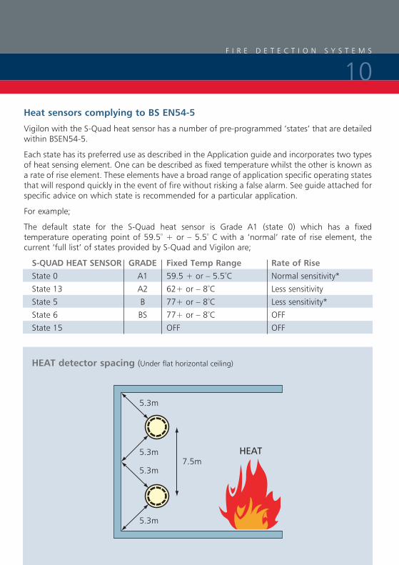
HEAT detector spacing (Under flat horizontal ceiling)
5.3m
5.3m7.5m
HEAT
5.3m
5.3m
Heat sensors complying to BS EN54-5
Vigilon with the S-Quad heat sensor has a number of pre-programmed ‘states’ that are detailed within BSEN54-5.
Each state has its preferred use as described in the Application guide and incorporates two types of heat sensing element. One can be described as fixed temperature whilst the other is known as a rate of rise element. These elements have a broad range of application specific operating states that will respond quickly in the event of fire without risking a false alarm. See guide attached for specific advice on which state is recommended for a particular application.
For example;
The default state for the S-Quad heat sensor is Grade A1 (state 0) which has a fixed temperature operating point of 59.5º + or – 5.5º C with a ‘normal’ rate of rise element, the current ‘full list’ of states provided by S-Quad and Vigilon are;
S-QUAD HEAT SENSOR GRADE Fixed Temp Range Rate of Rise State 0 A1 59.5 + or – 5.5ºC Normal sensitivity*
State 13 A2 62+ or – 8ºC Less sensitivity
State 5 B 77+ or – 8ºC Less sensitivity*
State 6 BS 77+ or – 8ºC OFF
State 15 OFF OFF
F I R E D E T E C T I O N S Y S T E M S
10
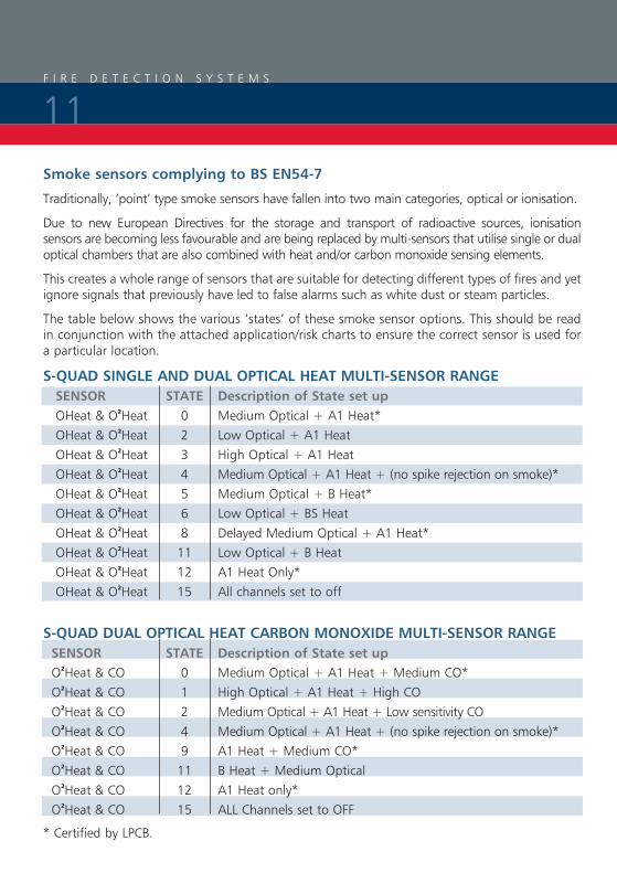
Smoke sensors complying to BS EN54-7
Traditionally, ‘point’ type smoke sensors have fallen into two main categories, optical or ionisation.
Due to new European Directives for the storage and transport of radioactive sources, ionisation sensors are becoming less favourable and are being replaced by multi-sensors that utilise single or dual optical chambers that are also combined with heat and/or carbon monoxide sensing elements.
This creates a whole range of sensors that are suitable for detecting different types of fires and yet ignore signals that previously have led to false alarms such as white dust or steam particles.
The table below shows the various ‘states’ of these smoke sensor options. This should be read in conjunction with the attached application/risk charts to ensure the correct sensor is used for a particular location.
S-QUAD SINGLE AND DUAL OPTICAL HEAT MULTI-SENSOR RANGE SENSOR STATE Description of State set up OHeat & O2Heat 0 Medium Optical + A1 Heat* OHeat & O2Heat 2 Low Optical + A1 Heat OHeat & O2Heat 3 High Optical + A1 Heat OHeat & O2Heat 4 Medium Optical + A1 Heat + (no spike rejection on smoke)* OHeat & O2Heat 5 Medium Optical + B Heat* OHeat & O2Heat 6 Low Optical + BS Heat OHeat & O2Heat 8 Delayed Medium Optical + A1 Heat* OHeat & O2Heat 11 Low Optical + B Heat OHeat & O2Heat 12 A1 Heat Only* OHeat & O2Heat 15 All channels set to off
S-QUAD DUAL OPTICAL HEAT CARBON MONOXIDE MULTI-SENSOR RANGE SENSOR STATE Description of State set up O2Heat & CO 0 Medium Optical + A1 Heat + Medium CO* O2Heat & CO 1 High Optical + A1 Heat + High CO O2Heat & CO 2 Medium Optical + A1 Heat + Low sensitivity CO O2Heat & CO 4 Medium Optical + A1 Heat + (no spike rejection on smoke)* O2Heat & CO 9 A1 Heat + Medium CO* O2Heat & CO 11 B Heat + Medium Optical O2Heat & CO 12 A1 Heat only* O2Heat & CO 15 ALL Channels set to OFF
* Certified by LPCB.
F I R E D E T E C T I O N S Y S T E M S
11
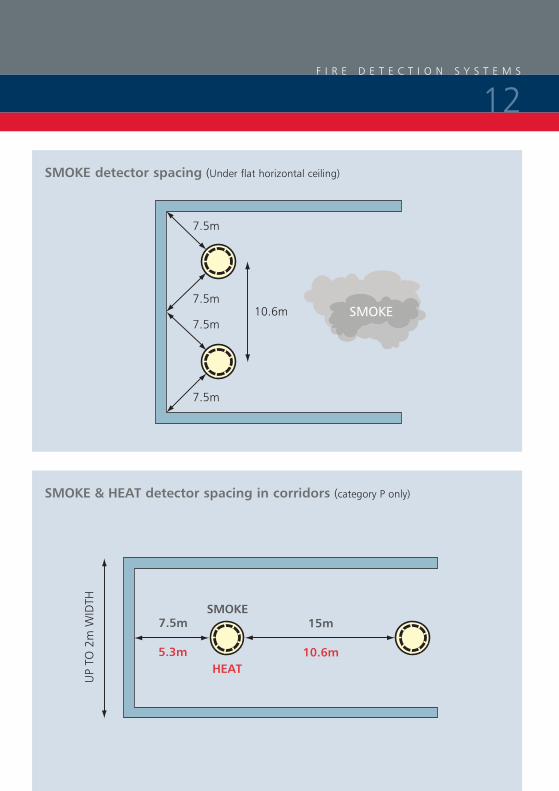
SMOKE detector spacing (Under flat horizontal ceiling)
7.5m
7.5m10.6m
7.5m
7.5m
SMOKE
SMOKE & HEAT detector spacing in corridors (category P only)
7.5m
UP
TO 2
m W
IDTH
5.3m
SMOKE
HEAT
15m
10.6m
F I R E D E T E C T I O N S Y S T E M S
12
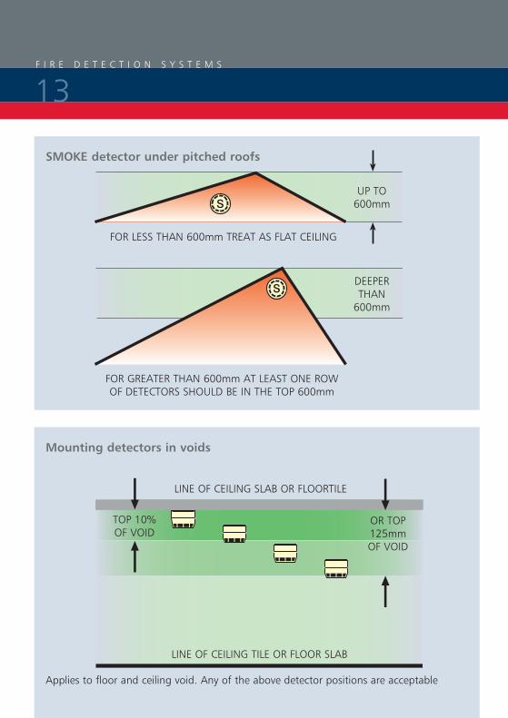
Mounting detectors in voids
SMOKE detector under pitched roofs
FOR LESS THAN 600mm TREAT AS FLAT CEILING
FOR GREATER THAN 600mm AT LEAST ONE ROW OF DETECTORS SHOULD BE IN THE TOP 600mm
Applies to floor and ceiling void. Any of the above detector positions are acceptable
LINE OF CEILING TILE OR FLOOR SLAB
LINE OF CEILING SLAB OR FLOORTILE
UP TO 600mm
DEEPER THAN
600mm
TOP 10%OF VOID
OR TOP 125mmOF VOID
F I R E D E T E C T I O N S Y S T E M S
13
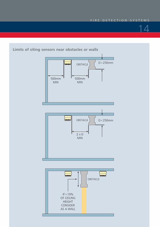
Limits of siting sensors near obstacles or walls
500mmMIN
500mmMIN
OBSTACLE D>250mm
2 x DMIN
OBSTACLE D<250mm
IF>10% OF CEILING
HEIGHT CONSIDER AS A WALL
OBSTACLE
F I R E D E T E C T I O N S Y S T E M S
14
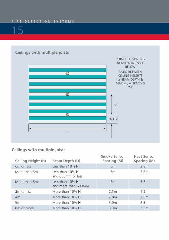
Smoke Sensor Heat Sensor Ceiling Height (H) Beam Depth (D) Spacing (M) Spacing (M) 6m or less Less than 10% H 5m 3.8m
More than 6m Less than 10% H 5m 3.8m and 600mm or less
More than 6m Less than 10% H 5m 3.8m and more than 600mm
3m or less More than 10% H 2.3m 1.5m
4m More than 10% H 2.8m 2.0m
5m More than 10% H 3.0m 2.3m
6m or more More than 10% H 3.3m 2.5m
Ceilings with multiple joists
Ceilings with multiple joists
PERMITTED SPACING DETAILED IN TABLE
BELOW
RATIO BETWEEN CEILING HEIGHTS vs BEAM DEPTH &
MAXIMUM SPACING‘M’
M
HALF M
L
F I R E D E T E C T I O N S Y S T E M S
15
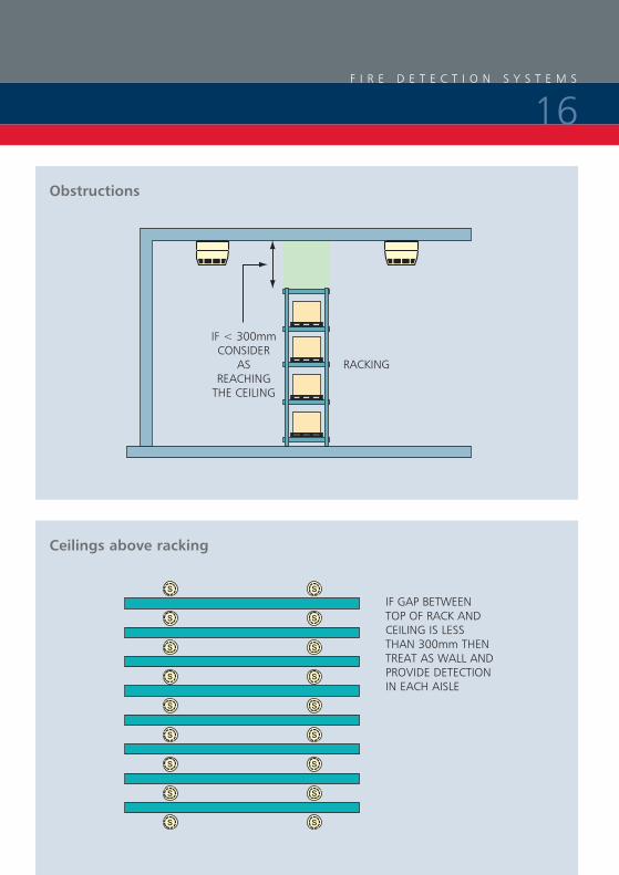
Ceilings above racking
Obstructions
IF GAP BETWEEN TOP OF RACK AND CEILING IS LESS THAN 300mm THEN TREAT AS WALL AND PROVIDE DETECTION IN EACH AISLE
IF < 300mmCONSIDER
AS REACHING
THE CEILING
RACKING
F I R E D E T E C T I O N S Y S T E M S
16

One of the most common mistakes is to mount a smoke sensor adjacent to the air conditioning intake or outlet grill. The minimum distance between the two should be at least 1 metre and further if possible. This is due to the fact that smoke may have difficulty penetrating the sensor when the air conditioning is switched on. Also there is a greater risk of the sensor becoming contaminated and giving rise to false alarms.
Ceilings with other obstructions or Air Handling units etc
AT LEAST 1m FROM
AN AIR HANDLING
UNIT
FREE 500mm SPACE BELOW
DETECTOR
STORAGE RACKS
ACCEPTABLE NOT ACCEPTABLE
F I R E D E T E C T I O N S Y S T E M S
17

Ceilings with perforated ceilings
DETECTORS ABOVE CEILINGS WITH PERFORATIONS CAN PROTECT THE AREA BELOW SUBJECT TO THE FOLLOWING CONDITIONS
3 THE PERFORATIONS ARE UNIFORM
3 THE MINIMUM PERFORATION IS > 10mm 3 THE THICKNESS IS < THAN 3 TIMES THE MINIMUM DIMENSION OF THE PERFORATION
Ceilings with perforated ceilings
WHERE AIR IS FORCED THROUGH A PERFORATED CEILING, THE DETECTOR SHOULD BE MOUNTED ON A SOLID BAFFLE WITH A MINIMUM DIAMETER OF 1200mm
F I R E D E T E C T I O N S Y S T E M S
18

Siting of BEAM detectors
ONE BEAM DETECTOR COVERS 17.5m USING EXTRA % ALLOWED DUE TO ANGLE OF ROOF
20m
17.5m
1.25m
2.5m
600mm 25º
GAP BETWEEN DETECTORS 12.5% AND 25% OF 10m MOUNTING HEIGHT = 1.25m AND 2.5m
3 General rules apply as for point detectors
3 For apex ceilings extend coverage by 1% for each degree of angle
3 600mm from the highest point
3 Avoid beams close to walls (500mm) or where temporary obstructions may occur
3 Mount transmitter & receivers on a solid surface not affected by wind natural temperature changes
3 Additional units may be included in atria to detect at lower levels, to counter stratification effect
F I R E D E T E C T I O N S Y S T E M S
19

Detector Type Maximum Up to 10% Heat detector - class A 9.0m 10.5m
Heat detector - other classes 7.5m 10.5m
Point type smoke detectors 10.5m 12.5m
Carbon monoxide detectors 10.5m 12.5m
Optical beam detectors 25.0m 25.0m
Aspiration - normal sensitivity 10.5m 12.5m
Aspiration - enhanced sensitivity 12.0m 14.0m
Aspiration - very high sensitivity 15.0m 18.0m
Limits of ceilings heights (General)
Choice and siting of alarm sounders and visual alarms
Sounders and strobes are generally provided for systems designed to protect life. However, on the rare occasion when only the property is being protected it is still essential to mount a sounder adjacent to the fire control panel as well as immediately outside the main entrance for the fire fighters.
Before deciding on the number and location of sounder/visual alarms, it is important to establish what the ‘Fire Plan’ or cause and effect will be.
If the building is not going to have a ‘one out –all out’ arrangement, the evacuation procedures must be established. Once this is known, you can then establish the alarm zone areas where different alarm messages may be given, for example an alert or an evacuation tone.
Design Stage 5
Design Tip 1 - Research* over the last twenty years has proven that a voice enhanced sounder is preferred to a bell or electronic sounder as people pay more attention to a spoken message. The Gent S-Cubed and S-Quad offer sounders that include recorded speech messages delivered in a synchronised manner to create a clear instruction to persons at risk within a building.
* Sources: Brian Piggott (The Fire Research Station) and David Canter (Surrey University)
F I R E D E T E C T I O N S Y S T E M S
20
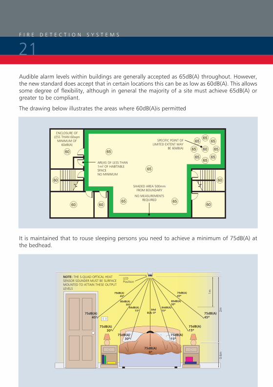
Audible alarm levels within buildings are generally accepted as 65dB(A) throughout. However, the new standard does accept that in certain locations this can be as low as 60dB(A). This allows some degree of flexibility, although in general the majority of a site must achieve 65dB(A) or greater to be compliant.
The drawing below illustrates the areas where 60dB(A)is permitted
It is maintained that to rouse sleeping persons you need to achieve a minimum of 75dB(A) at the bedhead.
656565
65
6565
65
6560
60
606060
60
60
6565
65
65
ENCLOSURE OF LESS THAN 60sqm
MINIMUM OF 60dB(A)
AREAS OF LESS THAN 1m2 OF HABITABLE SPACENO MINIMUM
SPECIFIC POINT OF LIMITED EXTENT MAY
BE 60dB(A)
SHADED AREA 500mmFROM BOUNDARY
NO MEASUREMENTSREQUIRED
NOTE: THE S-QUAD OPTICAL HEAT SENSOR SOUNDER MUST BE SURFACE MOUNTED TO ATTAIN THESE OUTPUT LEVELS
LED Position
1m
2m0.
6m
75dB(A)45º
79dB(A)45º
79dB(A)45º
80dB(A)30º
80dB(A)30º
84dB(A)15º
84dB(A)15º84d
B(A) 0º 75dB(A)45º
75dB(A)30º
75dB(A)30º
75dB(A)15º
75dB(A)15º
75dB(A)0º
F I R E D E T E C T I O N S Y S T E M S
21
For areas with high ambient background noise levels, the Standard recommends a sound level of 5dB(A) above the norm although it now goes on to say the maximum sound levels should not exceed 120dB(A) for health & safety reasons. Finally it is essential that at least one sounder is placed within each fire compartment and the sounder choice should be common throughout the building. You should not mix bells and electronic sounders within the same building although the Gent S-Cubed & S-Quad, both offer bell and electronic sounders allowing a system upgrade or switch over from a bell tone to an electronic tone when required.
Sound attenuation is affected by numerous physical structures within a room, including the door, furniture, people and materials used for floor, walls etc.
General internal doors will attenuate at least 20dB(A), whilst heavier fire doors may well attenuate by up 30dB(A). To ensure 75dB(A) is achieved within a bedroom it is accepted that the sounder is mounted within the room rather than the corridor outside. Use of sensor sounders ensures an even spread of sound throughout the building without the need for separate louder sounders. Visual alarms are generally considered as supplementary rather than the only means of providing an alarm, and are used in areas where the dB(A) level exceeds 90dB(A) or where persons within the area have impaired hearing. The exception could be where sound of any description is undesirable, for example operating theatres, TV studios and places of entertainment where a discreet staff alarm system is the best option to avoid panic.
Visual alarms are also included as a requirement of the Equality Act 2010 (formerly the Disability Discrimination Act 1995) and Approved Document Part M of the Building Regulations and should be included in all sleeping accommodation where people with a hearing disability may be present.
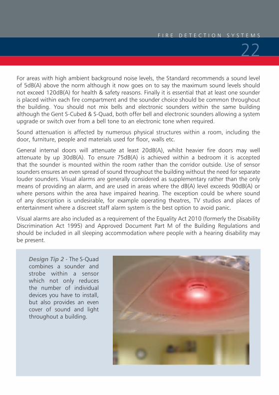
Design Tip 2 - The S-Quad combines a sounder and strobe within a sensor which not only reduces the number of individual devices you have to install, but also provides an even cover of sound and light throughout a building.
F I R E D E T E C T I O N S Y S T E M S
22

Control equipment & power supplies
The Control panel itself should comply to EN54-2 and any power supply used should comply to EN54-4. Today the majority of Gent fire control panels incorporate their own battery and charger and as long as the guidelines for loading these systems are complied with, the battery should be sufficient to maintain the system for a period of 24 hours with half an hour alarm load thereafter.
It is however recommended that a battery load calculation is carried out to verify the standby period provided by the capacity of the battery supplied.
Irrespective of the size or type of system the control panel should be sited with the following points in mind;
3 In an area of relatively low fire risk
3 On the ground floor entrance which the fire fighters will use
3 In buildings of multiple occupancy, the panel should be sited within a communal area or if this does not exist, a location which is accessible at all times
3 Where ambient light levels, ensure visibility at all times
3 Fire zonal indication should be clearly displayed by LEDs or an illuminated mimic diagram – it is not acceptable to simply accept the information from an LCD or VDU display
If there are several entrances to the building, consideration should be given to the provision of repeat indicators.
Design Stage 6
F I R E D E T E C T I O N S Y S T E M S
23
The Installers’ responsibilities:3 To install all equipment in accordance with the Standard
3 To use the correct types of cable
3 To test the cables, continuity and earth, and provide certificates
3 To flag up any Variations that affect the Design
3 To produce a set of ‘as fitted’ drawings
3 To sign off a G2 Installation certificate
Types of cable and where to use them
There are two basic grades of cable permitted for use on fire alarm systems. These are known as Standard grade and Enhanced grade designed to meet the new standards BS 8434-1 & BS 8434-2 respectively.
The choice of cable needed is dependent on how long the cable is expected to continue to operate whilst a fire is occurring.
The integrity of the system is paramount and all interconnections between devices must be considered especially those that affect the signals critical path.
Firstly the Standard insists that the mains supplies to the system, the manual call points and the automatic sensor circuits are wired in fire resistant cables.
What cable? - Standard or Enhanced fire resistant cables?
The Standard fire resistant cable will satisfy most applications particularly with ‘one out, all out’ fire plans. Enhanced fire resistant cables are required for applications that need communications to continue during a fire incident when the building fabric may be destroyed. Examples of where Enhanced fire resistant cable should be used include:
3 In un-sprinklered buildings where the ‘Fire Plan’ involves the evacuation of occupants in four or more phases
3 In un-sprinklered buildings greater than 30 metres in height
3 In un-sprinklered buildings or large networked sites where a fire could affect the cable’s ‘critical path’, particularly where people will remain in occupation during a fire elsewhere on the site
3 Where in part, a delayed evacuation may exist and the critical signal path may pass through an area of high risk
3 Where a Risk Assessment has identified a particular need for Enhanced cable
F I R E D E T E C T I O N S Y S T E M S
24
Other aspects in regard to Installation practice
3 The electrical characteristics of the cable such as impedance, capacitance etc should be capable of handling the data and power of the system.
3 For the Vigilon system, Gent regularly updates the list of approved standard and enhanced cables used for loops or networks. We would suggest you obtain the latest copy of our system data sheets or contact your local engineer to obtain the latest approved product.
Cable requirements
3 Core size not less than 1mm
3 Where exposed cables are below 2m, additional mechanical protection should be considered, except for cables complying to BS 7629
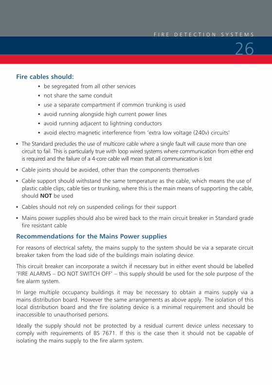
3 The colour of the outer sheath should preferably be RED although other colours are permitted as long as it is common throughout the building and does not clash with any other electrical services
STANDARD FIRE RESISTING CABLE
GROUND FLOOR
SIXTH FLOOR
FIFTH FLOOR
FOURTH FLOOR
THIRD FLOOR
SECOND FLOOR
FIRST FLOOR
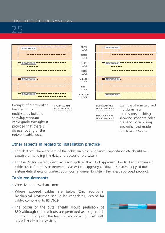
Example of a networked fire alarm in a multi-storey building, showing standard cable grade throughout provided that there is diverse routing of the network cable loop.
ENHANCED FIRE RESISTING CABLE
Example of a networked fire alarm in a multi-storey building, showing standard cable grade for local wiring and enhanced grade for network cable.
STANDARD FIRE RESISTING CABLE
F I R E D E T E C T I O N S Y S T E M S
25
Fire cables should: 3 be segregated from all other services
3 not share the same conduit
3 use a separate compartment if common trunking is used
3 avoid running alongside high current power lines
3 avoid running adjacent to lightning conductors
3 avoid electro magnetic interference from ‘extra low voltage (240v) circuits’
3 The Standard precludes the use of multicore cable where a single fault will cause more than one circuit to fail. This is particularly true with loop wired systems where communication from either end is required and the failure of a 4-core cable will mean that all communication is lost
3 Cable joints should be avoided, other than the components themselves
3 Cable support should withstand the same temperature as the cable, which means the use of plastic cable clips, cable ties or trunking, where this is the main means of supporting the cable, should NOT be used
3 Cables should not rely on suspended ceilings for their support
3 Mains power supplies should also be wired back to the main circuit breaker in Standard grade fire resistant cable
Recommendations for the Mains Power supplies
For reasons of electrical safety, the mains supply to the system should be via a separate circuit breaker taken from the load side of the buildings main isolating device.
This circuit breaker can incorporate a switch if necessary but in either event should be labelled ‘FIRE ALARMS – DO NOT SWITCH OFF’ – this supply should be used for the sole purpose of the fire alarm system.
In large multiple occupancy buildings it may be necessary to obtain a mains supply via a mains distribution board. However the same arrangements as above apply. The isolation of this local distribution board and the fire isolating device is a minimal requirement and should be inaccessible to unauthorised persons.
Ideally the supply should not be protected by a residual current device unless necessary to comply with requirements of BS 7671. If this is the case then it should not be capable of isolating the mains supply to the fire alarm system.
F I R E D E T E C T I O N S Y S T E M S
26

Commissioning Engineers’ responsibilities:
3 Functional testing of all equipment
3 Confirm fire plan or cause & effect is correct as per design
3 Look for any incorrect positioning of sensors or other devices – snag them or list them as Variations
3 Record sound level meter readings
3 Provide a log book and product manuals
3 Carry out staff training3 Collate all documents including 3 G1 Design Certificate 3 G2 Installation Certificate 3 G3 Commissioning Certificate (also sign it!) 3 Cable test and wiring certificate 3 Specification and drawings 3 List of agreed Variations 3 Fire Plan or ‘Cause and Effect’ 3 G4 Acceptance Certificate signed by clients representative
Inspection and testing of wiring
Prior to any equipment being connected, all installed cables should be subject to a 500V dc insulation test.
These tests should show an insulation value of at least 2Mohm between conductors and between each conductor and screen or earth.
Earth continuity tests should be carried out on all mains supply circuits as well as an earth loop impedance in accordance with BS 7671. It is important with the Vigilon system that all earth leads or screen cables are terminated and connected through each device.
The maximum impedance of each loop or radial circuit should be recorded to ensure it meets the manufacturers recommendations. In the case of Vigilon this is determined by not exceeding the recommended maximum cable lengths which for loop circuits should not be greater than 1Km and a maximum of 100metres for any radial circuit connected on a loop powered interface.
System Commissioning
F I R E D E T E C T I O N S Y S T E M S
27

It is important that the system is commissioned by a competent person who has attended recognised training courses on the equipment as well as the British Standard.
At this stage the entire system should be inspected and tested, in particular;
3 Every manual call point, sensor, sounder, interface and indicator
3 Check that all devices are correctly sited to cover the area they are intended to protect – see previous notes on siting of devices
3 Check that all devices are correctly labelled and display the correct information on the control panels
3 All sound pressure levels should be measured and recorded
3 Any transmission of signals to remote centres or equipment should be proven
3 The fire plan or cause and effect should be checked from every device
3 All alarm panels and printers display the correct information and are sited correctly
3 A suitable zone plan is mounted adjacent to the control panel
3 No changes to the building have affected the siting of equipment or effectiveness of the system for example an additional partition requiring additional sensors
3 Mains and standby power supplies are adequate and designed to support the system for a specified period, for example 24, 48 or 72 hours
3 As far as reasonable, ascertain that the installation complies with the standard and certificates are provided by the installer
3 If radio equipment is used, ensure all radio signals are of sufficient strength to ensure reliability
3 Ensure there are no obvious shortcomings with the system as a whole and that all the documentation is correct
It is also recommended that the system is soak tested for up to a week, dependent on the system size, so that any teething problems are identified without giving rise to any false alarms.
F I R E D E T E C T I O N S Y S T E M S
28

The purpose of this section of the guide to fire detection and alarm systems is to look at the simple guidelines an installer should follow when installing a Gent by Honeywell Vigilon or Nano Analogue Addressable system.
I N S T A L L A T I O N G U I D E
29
Vigilon Basic Loop Architecture
Please note that a Vigilon loop can accept upto 200 devices, the Nano single loop panel supports 127 devices.
Installation Guide
I N S T A L L A T I O N G U I D E
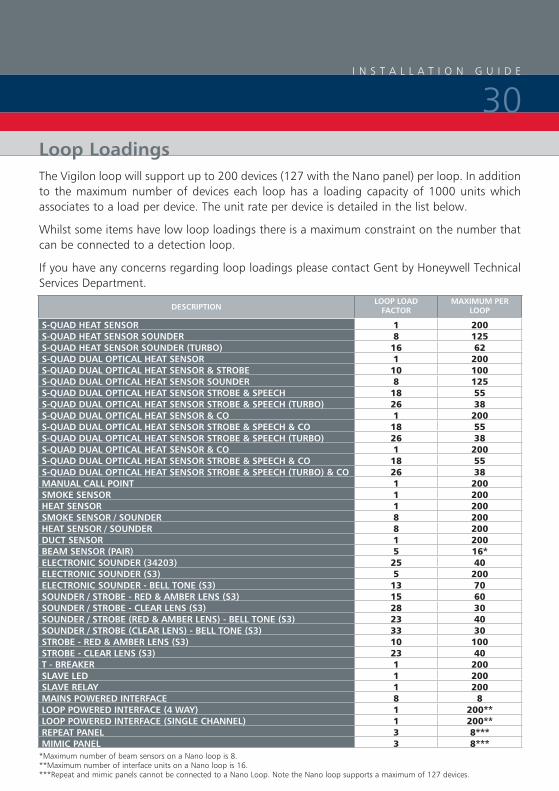
30Loop LoadingsThe Vigilon loop will support up to 200 devices (127 with the Nano panel) per loop. In addition to the maximum number of devices each loop has a loading capacity of 1000 units which associates to a load per device. The unit rate per device is detailed in the list below.
Whilst some items have low loop loadings there is a maximum constraint on the number that can be connected to a detection loop.
If you have any concerns regarding loop loadings please contact Gent by Honeywell Technical Services Department.
DESCRIPTIONLOOP LOAD
FACTORMAXIMUM PER
LOOP
S-QUAD HEAT SENSOR 1 200S-QUAD HEAT SENSOR SOUNDER 8 125S-QUAD HEAT SENSOR SOUNDER (TURBO) 16 62S-QUAD DUAL OPTICAL HEAT SENSOR 1 200S-QUAD DUAL OPTICAL HEAT SENSOR & STROBE 10 100S-QUAD DUAL OPTICAL HEAT SENSOR SOUNDER 8 125S-QUAD DUAL OPTICAL HEAT SENSOR STROBE & SPEECH 18 55S-QUAD DUAL OPTICAL HEAT SENSOR STROBE & SPEECH (TURBO) 26 38S-QUAD DUAL OPTICAL HEAT SENSOR & CO 1 200S-QUAD DUAL OPTICAL HEAT SENSOR STROBE & SPEECH & CO 18 55S-QUAD DUAL OPTICAL HEAT SENSOR STROBE & SPEECH (TURBO) 26 38S-QUAD DUAL OPTICAL HEAT SENSOR & CO 1 200S-QUAD DUAL OPTICAL HEAT SENSOR STROBE & SPEECH & CO 18 55S-QUAD DUAL OPTICAL HEAT SENSOR STROBE & SPEECH (TURBO) & CO 26 38MANUAL CALL POINT 1 200SMOKE SENSOR 1 200HEAT SENSOR 1 200SMOKE SENSOR / SOUNDER 8 200HEAT SENSOR / SOUNDER 8 200DUCT SENSOR 1 200BEAM SENSOR (PAIR) 5 16*ELECTRONIC SOUNDER (34203) 25 40ELECTRONIC SOUNDER (S3) 5 200ELECTRONIC SOUNDER - BELL TONE (S3) 13 70SOUNDER / STROBE - RED & AMBER LENS (S3) 15 60SOUNDER / STROBE - CLEAR LENS (S3) 28 30SOUNDER / STROBE (RED & AMBER LENS) - BELL TONE (S3) 23 40SOUNDER / STROBE (CLEAR LENS) - BELL TONE (S3) 33 30STROBE - RED & AMBER LENS (S3) 10 100STROBE - CLEAR LENS (S3) 23 40T - BREAKER 1 200SLAVE LED 1 200SLAVE RELAy 1 200MAINS POWERED INTERFACE 8 8LOOP POWERED INTERFACE (4 WAy) 1 200**LOOP POWERED INTERFACE (SINGLE CHANNEL) 1 200**REPEAT PANEL 3 8***MIMIC PANEL 3 8***
*Maximum number of beam sensors on a Nano loop is 8. **Maximum number of interface units on a Nano loop is 16. ***Repeat and mimic panels cannot be connected to a Nano Loop. Note the Nano loop supports a maximum of 127 devices.
I N S T A L L A T I O N G U I D E
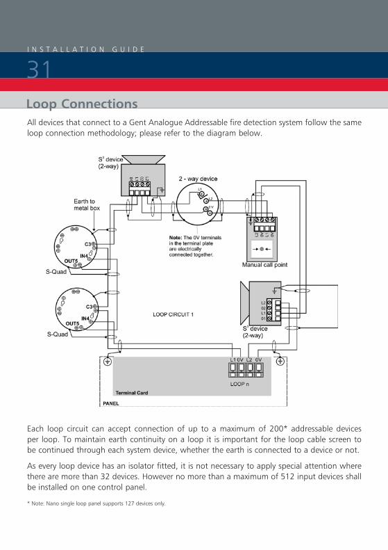
31Loop ConnectionsAll devices that connect to a Gent Analogue Addressable fire detection system follow the same loop connection methodology; please refer to the diagram below.
Each loop circuit can accept connection of up to a maximum of 200* addressable devices per loop. To maintain earth continuity on a loop it is important for the loop cable screen to be continued through each system device, whether the earth is connected to a device or not.
As every loop device has an isolator fitted, it is not necessary to apply special attention where there are more than 32 devices. However no more than a maximum of 512 input devices shall be installed on one control panel.
* Note: Nano single loop panel supports 127 devices only.

I N S T A L L A T I O N G U I D E
32Loop Length
The maximum loop resistance supported by the system is 13 ohms. The purpose of the loop resistance measurement is to check that the loop length is within the design limits for the system, and to indicate the likelihood of any issues with the loop cabling that might arise from, for instance loose terminations.
Using 1.5mm² cable, the resistance equating to 1km in length is 13ohms. In practice there will be additional resistance due to terminations at devices. It would not be unusal to measure a resistance of 15 ohms for a 1km loop. However if a resistance higher than this is measured this would indicate the the loop may be longer than 1km or that there may be some terminations that need attention. If the resistance is higher than 18 ohms there is potential for performance issues during the life of the system. Loops with a resistance greater than 18 ohms will not be guaranteed to work without problems and actions should be taken to reduce the loop length.
In summary, the resistance for loops should be a range up to 15 ohms. If the value is between 15 and 18 ohms the loop integrity should be investigated, but provided the system functions satisfactorily, no further action is necessary. If the loop resistance is greater than 18 ohms the loop length should be reduced, probably by the addition of an extra loop.

I N S T A L L A T I O N G U I D E
33
Standard cables (BS8434-1)
Approved EMC cables for loop wiring
Draka Firetuf EMC Standard 1.5mm2 FTEMC2EH1.5RDR
Draka Firetuf FTZ2E1.5 FIRETUF OHLS
Raydex CDT FG950
Cavicel SpA FIRECEL SR 114H
AEI Cables FIRETEC
BICC Pyrotenax FLAMESIL FRC
Datwyler LIFELINE
Alcatel cable PyROLON E
Huber & Suhner RADOX FR
Prysmian (formally Pirelli) FP200 FLEX
Prysmian (formally Pirelli) FP200 GOLD
Enhanced cables (BS8434-2)
Mineral insulated cable (MICC) to BS6207:Part 1
Draka Firetuf Plus Enhanced FTPLUS2EH1.5RD
Prysmian FP PLUS
Note: Please contact Gent by Honeywell Technical Support if the cable you intend using is not listed, to verify suitability.
Loop Cables
I N S T A L L A T I O N G U I D E
34
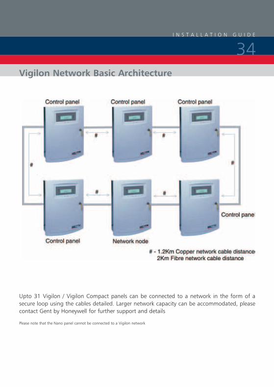
Upto 31 Vigilon / Vigilon Compact panels can be connected to a network in the form of a secure loop using the cables detailed. Larger network capacity can be accommodated, please contact Gent by Honeywell for further support and details
Please note that the Nano panel cannot be connected to a Vigilon network
Vigilon Network Basic Architecture

I N S T A L L A T I O N G U I D E
35Vigilon Network Connections
DO NOT mix cables of different types on the same network, as this will create impedance imbalance and disruption to data communication.
Network Cables
Standard Network Cables (BS 8434 Part 1)
Delta Crompton Firetuf FDZ1000
1200m maximum Panel to Panel or Panel to Network node cable distance, three core
Enhanced Network cables (BS 8434 Part 2)
Mineral insulated copper cable (EMC Compliant)
800m maximum Panel to Panel or Panel to network node cable distance.
3 BS6207: Part 1
3 3 parallel cores having continuous metal sheath encapsulating each core having 1.5mm2 cross section area a red cover sheath (preferred for alarm applications)
Fireshield Enhanced FSN G2000
1.2Km maximum Panel to Panel or Panel to Network node cable distance 3 Core (1 pair + 1 and earth each core having 1mm2 cross section area)
I N S T A L L A T I O N G U I D E
36Huber & Schner Radox series FR communication cable
1200m maximum Panel to Panel or Panel to Network node cable distance
3 Three core twisted triad screened 1.5mm2 (7/0.42 stranded) conductors Fire resistance tested to BS6387 category CWZ an IEC 331.
Belden No 9729 (UL Style 2493) (EMC Compliant)
1200m maximum Panel to Panel or Panel to Network node cable distance
3 Two twisted pairs. Each pair individually screened 24AWG
Teflon jacketed Belden TR No. 89729
1200m maximum Panel to Panel or Panel to Network node cable distance
3 Two twisted pairs. Each pair individually screened 24AWG
Belden Armoured equivalent (EMC Compliant)
1200m maximum Panel to Panel or Panel to Network node cable distance
3 Two twisted pairs. Each pair individually screened 24AWG
Belden No. 9842 EIA RS485 Applications, O/A Beldfoil® Braid
1200m maximum Panel to Panel or Panel to Network node cable distance
3 Two twisted pairs 24AWG
Prysmian (formally Pirelli) FP200 Flex (EMC Compliant)
800m maximum Panel to Panel or Panel to Network node cable distance
3 3 Core each core having 1.5mm2 cross section area
Prysmian (formally Pirelli) FP200 Gold (EMC Compliant)
1.2Km maximum Panel to Panel or Panel to Network node cable distance
3 3 Core each core having 1.5mm2 cross section area
Prysmian (formally Pirelli) FP Plus (EMC Compliant)
1.2Km maximum Panel to Panel or Panel to Network node cable distance
3 3 Core each core having 1.5mm2 cross section area
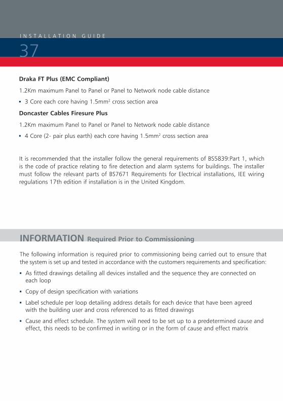
Draka FT Plus (EMC Compliant)
1.2Km maximum Panel to Panel or Panel to Network node cable distance
3 3 Core each core having 1.5mm2 cross section area
Doncaster Cables Firesure Plus
1.2Km maximum Panel to Panel or Panel to Network node cable distance
3 4 Core (2- pair plus earth) each core having 1.5mm2 cross section area
It is recommended that the installer follow the general requirements of BS5839:Part 1, which is the code of practice relating to fire detection and alarm systems for buildings. The installer must follow the relevant parts of BS7671 Requirements for Electrical installations, IEE wiring regulations 17th edition if installation is in the United Kingdom.
I N S T A L L A T I O N G U I D E
37
INFORMATION Required Prior to Commissioning
The following information is required prior to commissioning being carried out to ensure that the system is set up and tested in accordance with the customers requirements and specification:
3 As fitted drawings detailing all devices installed and the sequence they are connected on each loop
3 Copy of design specification with variations
3 Label schedule per loop detailing address details for each device that have been agreed with the building user and cross referenced to as fitted drawings
3 Cause and effect schedule. The system will need to be set up to a predetermined cause and effect, this needs to be confirmed in writing or in the form of cause and effect matrix

I N S T A L L A T I O N G U I D E
38
INFORMATION Required Prior to Commissioning
DEVICE LABEL SCHEDULE
PROjECT Page x or x
LOCATION Panel No
???
DEVICE
REFERENCE
ON
DRAWING
Type of device
Device lable (Description to be displayed on panel) N.B MCP automatically display MCP using four characters
Panel No
1 2 3 4 5 6 7 8 9 101112131415161718192021222324252627282930
I N S T A L L A T I O N G U I D E
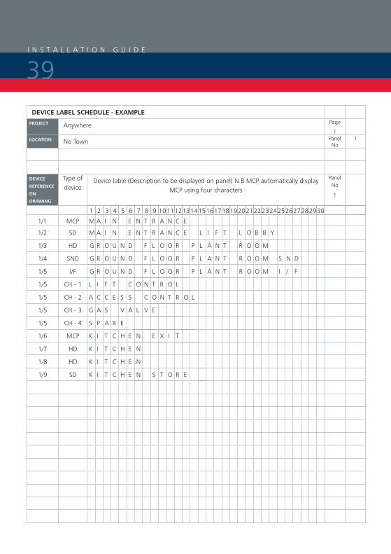
39DEVICE LABEL SCHEDULE - EXAMPLE
PROjECT Anywhere Page
1LOCATION No Town Panel
No1
DEVICE
REFERENCE
ON
DRAWING
Type of device
Device lable (Description to be displayed on panel) N.B MCP automatically display MCP using four characters
Panel No
1
1 2 3 4 5 6 7 8 9 101112131415161718192021222324252627282930
1/1 MCP M A I N E N T R A N C E
1/2 SD M A I N E N T R A N C E L I F T L O B B Y
1/3 HD G R O U N D F L O O R P L A N T R O O M
1/4 SND G R O U N D F L O O R P L A N T R O O M S N D
1/5 I/F G R O U N D F L O O R P L A N T R O O M I / F
1/5 CH - 1 L I F T C O N T R O L
1/5 CH - 2 A C C E S S C O N T R O L
1/5 CH - 3 G A S V A L V E
1/5 CH - 4 S P A R E
1/6 MCP K I T C H E N E X I T
1/7 HD K I T C H E N
1/8 HD K I T C H E N
1/9 SD K I T C H E N S T O R E

I N S T A L L A T I O N G U I D E
40
1 2 3 4 5 6 7 8 9
1
2
3
4
5
6
7
8
9
Zoning
Second floor 1 2 3
First floor 4 5 6
Ground floor 7 8 9
Detectionin zone
Alarmin zone
Evacuate Alert
Cause and Effect Matrix
I N S T A L L A T I O N G U I D E
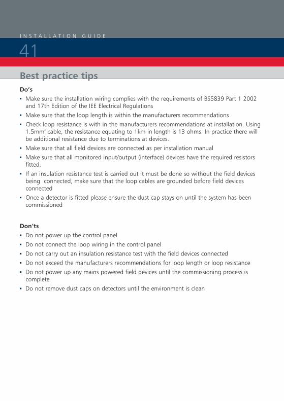
41Best practice tipsDo’s3 Make sure the installation wiring complies with the requirements of BS5839 Part 1 2002 and 17th Edition of the IEE Electrical Regulations
3 Make sure that the loop length is within the manufacturers recommendations
3 Check loop resistance is with in the manufacturers recommendations at installation. Using 1.5mm² cable, the resistance equating to 1km in length is 13 ohms. In practice there will be additional resistance due to terminations at devices.
3 Make sure that all field devices are connected as per installation manual
3 Make sure that all monitored input/output (interface) devices have the required resistors fitted.
3 If an insulation resistance test is carried out it must be done so without the field devices being connected, make sure that the loop cables are grounded before field devices connected
3 Once a detector is fitted please ensure the dust cap stays on until the system has been commissioned
Don’ts3 Do not power up the control panel
3 Do not connect the loop wiring in the control panel
3 Do not carry out an insulation resistance test with the field devices connected
3 Do not exceed the manufacturers recommendations for loop length or loop resistance
3 Do not power up any mains powered field devices until the commissioning process is complete
3 Do not remove dust caps on detectors until the environment is clean
I N S T A L L A T I O N G U I D E
42
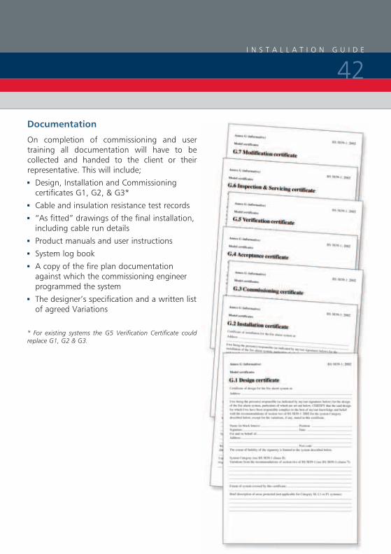
Documentation
On completion of commissioning and user training all documentation will have to be collected and handed to the client or their representative. This will include;
3 Design, Installation and Commissioning certificates G1, G2, & G3*
3 Cable and insulation resistance test records
3 “As fitted” drawings of the final installation, including cable run details
3 Product manuals and user instructions
3 System log book
3 A copy of the fire plan documentation against which the commissioning engineer programmed the system
3 The designer’s specification and a written list of agreed Variations
* For existing systems the G5 Verification Certificate could replace G1, G2 & G3.

Complete Detection Systems Limited, formed in 1988, is now one of the leading established
independent fire alarm service providers in the UK. Our engineers are strategically located to
offer fast and effective response to emergency call outs 24 hours, 365 days of the year. Our
service base is now in excess of 3000 sites.
Our design team operates to current BS standards and liaises closely with our field engineers
ensuring a smooth transition through to commissioning and handover.
CDS is listed in the BAFE list of registered companies having fully complied with the
requirements of the BAFE adopted scheme for the design, installation, commissioning/handover
and maintenance of fire detection and alarm systems- BAFE certificate number 100195/BSI
certificate number KM 550306.

F I R E A L A R M S P E C I A L I S T
D E S I G N
S U P P LY
I N S TA L L AT I O N
M A I N T E N A N C E & S E R V I C E
2 4 H O U R C A L L O U T
S P E C I A L I S T D E T E C T I O N

Complete Detection Systems LTD
9 -10 Froanes Close
Enderby
Leicestershire
LE19 4XL
Telephone: (0116) 275 0177
Fax: (0116) 275 2177
E-mail: [email protected]
www.cdsys.co.uk
The Gent 24 nationwide network of approved system integrators consists of over 60 specialist companies who can supply Gent by Honeywell equipment and carry out design, installation, commissioning and maintenance operations to the highest standards of workmanship
E L I T E S Y S T E M S I NTE
GR
AT
OR
E L I T E S Y S T E M S I NTE
GR
AT
OR
www.cdsys.co.uk