fire service summary report - ulfirefightersafety.org · opening. while no known ... effective. the...
TRANSCRIPT
Fire Service Summary Report: Study of the Effectiveness of Fire Service Vertical Ventilation and Suppression Tactics in Single Family Homes


Forward This document is a subset of the full technical report titled, Study of the Effectiveness of Fire Service Vertical Ventilation and Suppression Tactics in Single Family Homes,” that can be downloaded at www.ULfirefightersafety.com. There is no additional information provided in this document rather it includes introductory material, a summary of the experimental setup, fire service tactical considerations and summary of the full report. Please refer to the full report for more detail and discussion of the results.
1. Introduction There is a continued tragic loss of firefighter and civilian lives, as shown by fire statistics. One significant contributing factor is the lack of understanding of fire behavior in residential structures resulting from the use of ventilation as a firefighter practice on the fire ground. The changing dynamics of residential fires as a result of the changes in home construction materials, contents, size and geometry over the past 30 years compounds our lack of understanding of the effects of ventilation on fire behavior (Kerber S. , 2012). If used properly, ventilation improves visibility and reduces the chance of flashover or back draft. If a fire is not properly ventilated, it could result in an anticipated flashover, greatly reducing firefighter safety (Kerber S. , 2012). This fire research project developed empirical data from full-scale house fire experiments to examine vertical ventilation, suppression techniques and the resulting fire behavior. The purpose of this study was to improve firefighter knowledge of the effects of vertical ventilation and the impact of different suppression techniques. The experimental results may be used to develop tactical considerations outlining firefighting ventilation and suppression practices to reduce firefighter death and injury. This fire research project will further work from previous DHS AFG sponsored research (EMW-2008-FP-01774), which studied the impact of horizontal ventilation through doors and windows (Kerber S. , 2010).
1.1. Background NFPA estimates that from 2002-2011 (Karter, 2012), U.S. fire departments responded to an average of 398,000 residential fires annually. These fires caused an estimated annual average of 2,820 civilian deaths and 13,780 civilian injuries. More than 70% of the reported home fires and 84% of the fatal home fire injuries occurred in one- or two- family dwellings, with the remainder in apartments or similar properties. For the 2006-2009 period, there were an estimated annual average 35,743 firefighter fire ground injuries in the U.S. (Michael J. Karter & Molis, 2010) The rate of traumatic firefighter deaths occurring outside structures or from cardiac arrest has declined, while at the same time, firefighter deaths occurring inside structures has continued to climb over the past 30 years (Fahy, LeBlanc, & Molis, 2007). Improper ventilation tactics are believed to be a significant contributing factor to the increase in firefighter injuries and deaths. Ventilation is frequently used as a firefighting tactic to control and fight fires. In firefighting, ventilation refers to the process of creating openings to remove smoke, heat and toxic gases from a burning structure and replacing them with fresh air. If used properly, ventilation improves visibility and reduces the chance of flashover or back draft. If a large fire is not properly ventilated, not only will it be much harder to fight, but it could also build up enough poorly

burned smoke to create a back draft or smoke explosion, or enough heat to create flashover. Poorly placed or timed ventilation may increase the fire’s air supply, causing it to grow and spread rapidly. Used improperly, ventilation can cause the fire to grow in intensity and potentially endanger the lives of fire fighters who are between the fire and the ventilation opening. While no known studies compile statistics on ventilation induced fire injuries and fatalities, the following are examples of recent ventilation induced fires that resulted in fire fighter injuries and fatalities.
1) 2 NIOSH fatality investigation reports, 98-FO7 (NIOSH, Commercial Structure Fire Claims the Life of One Fire Fighter—California, 1998) and F2004-14 (NIOSH, 2005) involved “offensive entry (that) was not coordinated with ventilation that was complete and effective” that resulted in multiple firefighter fatalities; 2) “While attempting to assess the extent of the fire in the attic, one of the firefighters operating on the roof fell through the weakened roof decking. The firefighter suffered burn injuries as a result of this fall. His SCBA and face piece were torn off by the rafters during the fall.” (National Firefighter Near Miss Reporting System, 2009) 3) A February 29, 2008 duplex fire resulted in 1 firefighter death and 1 resident death as a result of, among other factors, “lack of coordinated ventilation”. NIOSH report conclusion states “This contributory factor (tactical ventilation) points to the need for training on the influence of tactical operations (particularly ventilation) on fire behavior”. (NIOSH, 2008) ; 4) NIOSH fatality investigation report F2007-29 reports of a fire in a residential structure and states “…Horizontal and vertical ventilation was conducted and a powered positive pressure ventilation fan was utilized at the front door but little smoke was pushed out. Minutes later, heavy dark smoke pushed out of the front door…. Two victims (firefighters) died of smoke inhalation and thermal injuries.” (NIOSH, 2008); 5) While not a residential fire, the Charleston, SC fire on June 18, 2008 that resulted in 9 firefighter deaths reported that misuse of ventilation was one contributing factor. The recent NIOSH report on this event stated “A vent opening made between the fire fighter or victims and their path of egress could be fatal if the fire is pulled to their location or cuts off their path of egress.” (NIOSH, 2009) 6) A recent NIOSH publication documents the extent of the situation “Lives will continue to be lost unless fire departments make appropriate fundamental changes in fire-fighting tactics involving trusses. These fundamental changes include the following: Venting the roof using proper safety precautions.” (NIOSH, 2010)
As fire grows from the single ignited item to other objects in the room of fire origin, it may become ventilation controlled depending on how well the fire compartment (i.e., home) is sealed. At this stage both the fire growth and power (heat release rate) are limited by available ventilation. If the compartment is tightly sealed, the fire may ultimately self-extinguish. However, if ventilation is increased, either through tactical action of the firefighters or unplanned ventilation resulting from effects of the fire (e.g., failure of a window, ceiling, roof) or human

action (e.g., door opened), heat release will increase, potentially resulting in ventilation induced flashover conditions. These ventilation induced fire conditions are sometimes unexpectedly swift, providing little time for firefighters to react and respond. Compounding the problem with ventilation is the changing dynamics of residential fires due to the changes in new contemporary home construction including new building materials, contents, size and layout. Many contemporary homes are larger than older homes built before 1980. Newer homes tend to incorporate open floor plans, with large spaces that contribute to rapid fire spread. The challenge of rapid fire spread is exacerbated by the use of modern building materials, construction practices, and contents. The rising cost of energy and developments of “green” building design have resulted in a significant change in attic design. Emerging trends, such as tempered attic spaces, have resulted in a shift from traditional cellulosic and fiberglass batting installed in the attic floor joists to spray applied foams installed to the underside of the roof deck. Previous research developed experimental fire test data and was used to demonstrate fire behavior resulting from varied horizontal ventilation opening locations (doors and windows) in legacy residential structures compared to modern residential structures. This project advances knowledge by investigating the effect of vertical ventilation through ceiling / attic / roofs. Many positive responses were received from firefighters following the release of the previous research project’s online training program. In addition, it was requested that UL address vertical ventilation and further address suppression tactics. This study will address these requests and the lack of available data. The data will be used to provide education and guidance to the fire service in proper use of vertical ventilation as a firefighting tactic that will result in mitigation of the firefighter injury and death risk associated with improper use of ventilation.
1.2. Understanding Limitations Every fire event that the fire service responds to is unique, as the range of fire ground variables at each fire event makes firefighting complex. In this investigation, key variables were identified and bounded to develop the data under controlled conditions. These variables included house geometry, fuel loading, fire department arrival time, tactical choices, hose stream flow rates, and ventilation locations. By bounding these variables and controlling the test conditions during firefighting operations, the impact of vertical ventilation operations and fire suppression tactics on fire dynamics and conditions in two types of single family homes was examined. The results enable the establishment of a scientific basis that may be used for other types of structures that are not single family homes, different sized rooms, different fuel loads, different interior geometries, different timing of operations, etc. The purpose of this study is not to establish if vertical ventilation or exterior suppression is more effective. The purpose is to increase the fire service’s knowledge of the impact of these tactics under specific conditions. Since all fire ground circumstances cannot be analyzed, it is anticipated that the data developed and this analysis enable firefighters to complement their previous observations and experiences. This study does not consider the safety of physically conducting vertical ventilation operations. As shown in previous UL studies, wood roof systems burn and collapse which makes operating on top of a roof on fire a dangerous operation that should only be done with a risk/benefit

analysis by the firefighters. Many firefighters have lost their lives due to collapse of a roof system while performing vertical ventilation. The information from this report can be incorporated into the size-up considerations of the fire service so that vertical ventilation is used to the best benefit possible when it is determined to be an appropriate tactic. The fires in this study, where vertical ventilation was used, were content fires and represented a fire event within the living space of the home, and not a structure fire with fire extension into the attic space. These experiments were also meant to simulate initial fire service operations by an engine company or engine and truck company arriving together in short order with approximately national average response times. Additional experiments have been conducted to begin to examine vertically ventilating an attic fire and will be documented separately.
2. Project Technical Panel A technical panel of fire service and research experts was assembled based on their previous experience with research studies, ventilation practices, scientific knowledge, practical knowledge, professional affiliations, and dissemination to the fire service. They provided valuable input into all aspects of this project, such as experimental design and identification of tactical considerations. The panel made this project relevant and possible for the scientific results to be applicable to firefighters and officers of all levels. The panel consisted of:
Josh Blum, Deputy Chief, Loveland – Symmes (OH) Fire Department John Ceriello, Lieutenant, Fire Department of New York James Dalton, Coordinator of Research, Chicago Fire Department Ed Hadfield, Division Chief, City of Coronado (CA) Fire Department Todd Harms, Assistant Chief, Phoenix Fire Department Ed Hartin, Chief, Central Whidbey Island Fire Rescue Department George Healy, Battalion Chief, Fire Department of New York Otto Huber, Fire Chief, Loveland – Symmes (OH) Fire Department Dan Madrzykowski, Fire Protection Engineer, National Institute of Standards and
Technology Mark Nolan, Fire Chief, City of Northbrook (IL) David Rhodes, Battalion Chief, Atlanta Fire Department David Rickert, Firefighter, Milwaukee Fire Department Andy Rick, Firefighter, Lake Forest (IL) Fire Department Pete Van Dorpe, Chief of Training, Chicago Fire Department Sean DeCrane, Battalion Chief, Cleveland Fire Department Bobby Halton, Editor, Fire Engineering Magazine Harvey Eisner, Editor, Firehouse Magazine Tim Sendelbach, Editor, Fire Rescue Magazine
3. Full-Scale House Experiments The project technical panel designed a series of 17 experiments to examine several scenarios that were identified as gaps in current fire service knowledge of fire dynamics, ventilation and suppression. These gaps include:

Impact of door control Impact of vertical ventilation hole size Impact of vertical ventilation hole location Impact of different flow paths between fire location and ventilation location Impact of modern and legacy fuel loads in a structure Impact of exterior suppression with various flow path configurations
To examine these knowledge gaps in vertical ventilation practices, suppression practices as well as the impact of changes in modern house geometries and contents, two houses were constructed in the large fire facility of Underwriters Laboratories in Northbrook, IL. Seventeen experiments were conducted, varying the ventilation locations, fire ignition location and the timing of ventilation openings (Table 3.1 and Table 3.2). Ventilation scenarios included ventilating the front door and a window near the seat of the fire to link these experiments to previous horizontal ventilation experiments, opening the front door and a ventilation hole above the seat of the fire and remote from the seat of the fire, and opening the front door and opening a large hole above the fire. Suppression scenarios included igniting a fire in the kitchen, opening the front door and flowing water into the kitchen with the dining room window closed and open. Another suppression experiment included igniting a fire in the living room, creating a flow path from the front door through Bedroom 1 and flowing water through the front door. A final scenario in the 1-story house examined opening the front door and living room window while the living room was furnished with legacy fuel. Details of the structures, instrumentation, fuel load and results follow in this section. Table 3.1: One-Story Experimental Details
Experiment #
Structure Location of Ignition
Ventilation Parameters
1 1-Story Living Room Front Door + Living Room Window 3 1-Story Living Room Front Door Partially Open + Roof (4' by 4') 5 1-Story Living Room Front Door + Roof (4' by 4') 7 1-Story Living Room Front Door + Roof (4' by 8') 9 1-Story Bedroom 1 Front Door + Roof (4' by 4') +
Bedroom 1 Window 11 1-Story Bedroom 1 Bedroom 1 Window + Front Door +
Roof (4' by 4') 13 1-Story Kitchen Front Door + Dining Room Window 15 1-Story Living Room Living Room + Bedroom 1 Window 17 1-Story Living Room Front Door + Living Room Window
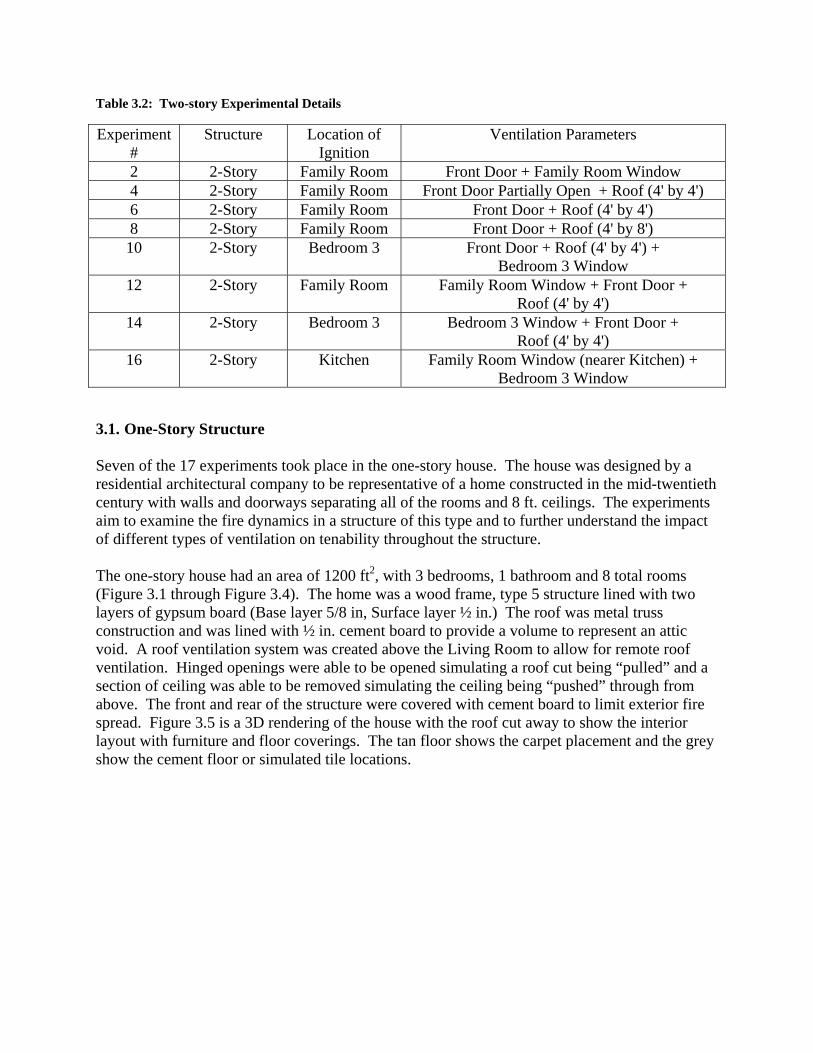
Table 3.2: Two-story Experimental Details
Experiment #
Structure Location of Ignition
Ventilation Parameters
2 2-Story Family Room Front Door + Family Room Window 4 2-Story Family Room Front Door Partially Open + Roof (4' by 4') 6 2-Story Family Room Front Door + Roof (4' by 4') 8 2-Story Family Room Front Door + Roof (4' by 8') 10 2-Story Bedroom 3 Front Door + Roof (4' by 4') +
Bedroom 3 Window 12 2-Story Family Room Family Room Window + Front Door +
Roof (4' by 4') 14 2-Story Bedroom 3 Bedroom 3 Window + Front Door +
Roof (4' by 4') 16 2-Story Kitchen Family Room Window (nearer Kitchen) +
Bedroom 3 Window
3.1. One-Story Structure Seven of the 17 experiments took place in the one-story house. The house was designed by a residential architectural company to be representative of a home constructed in the mid-twentieth century with walls and doorways separating all of the rooms and 8 ft. ceilings. The experiments aim to examine the fire dynamics in a structure of this type and to further understand the impact of different types of ventilation on tenability throughout the structure. The one-story house had an area of 1200 ft2, with 3 bedrooms, 1 bathroom and 8 total rooms (Figure 3.1 through Figure 3.4). The home was a wood frame, type 5 structure lined with two layers of gypsum board (Base layer 5/8 in, Surface layer ½ in.) The roof was metal truss construction and was lined with ½ in. cement board to provide a volume to represent an attic void. A roof ventilation system was created above the Living Room to allow for remote roof ventilation. Hinged openings were able to be opened simulating a roof cut being “pulled” and a section of ceiling was able to be removed simulating the ceiling being “pushed” through from above. The front and rear of the structure were covered with cement board to limit exterior fire spread. Figure 3.5 is a 3D rendering of the house with the roof cut away to show the interior layout with furniture and floor coverings. The tan floor shows the carpet placement and the grey show the cement floor or simulated tile locations.

Figure 3.1: One-Story Front
Figure 3.2: One-Story Roof
Figure 3.3: One-Story Rear

Figure 3.4: One-Story House Floor Plan
Figure 3.5: 3D Rendering of the One-Story House from the Front

3.2. Two-Story Structure The two-story house had an area of 3200 ft2, with 4 bedrooms, 2.5 bathrooms house and 12 total rooms (Figure 3.6 through Figure 3.12). This home was also a wood frame, type 5 structure lined with two layers of gypsum board (Base layer 5/8 in, Surface layer ½ in.) The roof was engineered I-joist construction but not sheathed because the fires were content fires only and not structure fires. A roof ventilation system was created above the Family Room to allow for remote roof ventilation. Hinged sections of roof could be opened to simulate a roof cut being completed. This section did not have an interior ceiling to be “pushed” because this section of the roof above the great room was simulated to be a cathedral style ceiling, having no void below the roof. The front and rear of the structure were covered with cement board to limit exterior fire spread.
Figure 3.6: Two-Story Front Figure 3.7: Two-Story Rear
Figure 3.8: Two-Story Roof

Figure 3.9. 3D Rendering of the 2-Story House from the Front
Figure 3.10. 3D Rendering of the 2-Story House from the Back

Figure 3.11. Two-Story House First Floor Plan
Figure 3.12. Two-Story House Second Floor Plan

3.3. Experimental Methodology All of the experiments started with the exterior doors and windows closed, the roof vents closed, and all of the interior doors in the same locations (i.e., either open or closed). The fire was ignited using a remote ignition device comprising of five stick matches (Figure 3.13) and electrically energized with a fine wire to heat the match heads, and create a small flaming ignition source. The ignition locations are shown in Figure 3.14 through Figure 3.16.
Figure 3.13: Ignition Matches Figure 3.14: One-Story Living Room Ignition Location
Figure 3.15: Two-Story Family Room Ignition Location
Figure 3.16: Bedroom Ignition Location
The flaming fire was allowed to grow until ventilation operations were performed by making openings. The one story house was ventilated 8 minutes after ignition. This was determined based on two factors: time to achieve ventilation-limited conditions in the house and potential response and intervention times of the fire service. The ventilation time for the two story house was 10 minutes for the same reasons as the one story house and the additional time enabled ventilation-limited conditions. The same fuel package was used in the two-story family room with a 17 ft. ceiling and open floor plan as was used in the one-story house with an 8 ft ceiling and compartmented floor plan therefore the two-story house required a longer time to become ventilation-limited. Ventilation scenarios included ventilating the front door and a window near the seat of the fire to link these experiments to previous horizontal ventilation experiments, opening the front door and a ventilation hole above the seat of the fire and remote from the seat of the fire, and opening the

front door and opening a large hole above the fire. Suppression scenarios included igniting a fire in the kitchen, opening the front door and flowing water into the kitchen with the dining room window closed and open. Another suppression experiment included igniting a fire in the living room, creating a flow path from the front door through Bedroom 1 and flowing water through the front door. A final scenario in the 1-story house examined opening the front door and living room window while the living room was furnished with legacy fuel. In most cases in the field vertical ventilation and horizontal ventilation are performed at different time scales. There is an obvious difference between ventilating a glass window with a tool from the ground versus climbing to the roof and creating a ventilation hole through the roof membrane. Therefore, the timing of the vertical ventilation openings was done based on interior conditions and not a certain time. The most frequent criteria chosen was a 3 ft. temperature of 400 °F in the area that a firefighting crew could be operating. This approach may be justified by the fact that a crew operating in that area could request that vertical ventilation is completed to improve the conditions in the area in which they were operating. The timing of these openings will be explained and examined for each experiment in the discussion section of the report. After ventilation, the fire was allowed to grow until flashover or perceived maximum burning rate occurred. This was based on the temperatures, observation of exterior conditions, and monitoring of the internal video. Once the fire maintained a peak for a period of time with respect given to wall lining integrity (prior to transition from a content fire to a structure fire), a hose stream was flowed in through an external opening. Incorporated into every experiment was a stream of water directed into a ventilation opening for approximately 15 seconds. The hose line used was a 1 ¾ inch with a combination nozzle with approximately 100 psi nozzle pressure, creating a flow of 100 gpm. Two types of flow patterns were used during the experiments, straight stream and fog. During straight stream application the nozzle was adjusted to a straight stream pattern and directed into the structure with the guidance of putting water on what was burning, so the nozzle was not held stationary. During the fog stream application the nozzle was adjusted to create an approximate 30 degree fog pattern and also directed into the structure with the intent to extinguish the visible fire while not holding the nozzle stationary. The flow rate of the nozzle was 100 gpm resulting in approximately 25 gallons of water delivered through the opening into the house during the 15 second flow. The purpose of this flow was not to enable firefighters to move into the structure and extinguish the fire but to suppress as much fire as possible and to observe the conditions in the surrounding rooms. This has an impact on the tactical considerations as discussed later in the report. This would allow the potential fire attack crew to slow the fire down, or soften the target, prior to making entry, therefore make entry into a safer environment. The experiment was terminated at least one minute after the hose stream, and suppression was completed by the firefighting crew.

4. Tactical Considerations In this section, the results of all the experiments are discussed to develop relationship to tactics on the fire ground as it may impact the safety of the fire service. The topics examined in this section were identified by the project's technical panel. The application of the findings discussed in this section to the fire scene depend upon many factors such as (i) building structure; (ii) capabilities and resources available to the first responding fire department; and (iii) availability of mutual aid. In addition, the tactical considerations provided should be viewed as concepts for the responding fire service personnel to consider at the fire scene.
4.1. Modern versus Legacy Fire Development As more and more home furnishings are made of synthetic materials, the heat release rate generated by furniture has increased significantly. This change speeds up the stages of fire development, creating an increased potential for ventilation-limited fire conditions prior to fire department arrival. The fire service’s workplace has changed and one of several significant factors is home furnishings. As home furnishings have evolved over decades to be made of synthetic materials, the heat release rates generated by home furnishings have increased significantly. This change speeds up the stages of fire development creating an increased potential for ventilation-limited fire conditions prior to fire department arrival. Earlier ventilation-limited conditions make the ventilation tactics of the fire service of utmost importance. Figure 4.1 details many differences of how fires develop today versus decades ago. Peak temperatures prior to becoming ventilation-limited are very different: 1100 °F in the modern fire, compared to 450 °F in the legacy fire. The minimum oxygen concentration prior to fire service ventilation was 5% in the modern fire, compared to 18% in the legacy fire. Most importantly, the time between ventilation and flashover are 2 minutes for the modern fire and over 8 minutes in the legacy fire. The legacy fire could be described as forgiving as it pertains to ventilation. Poorly timed ventilation or an uncoordinated attack can be made up for prior to flashover because there is 8 minutes to adapt. The time to recover in the modern fire was only 2 minutes, or 25% of the legacy time. This supports the adage, “You are not fighting your grandfather's fire anymore.”

Figure 4.1
4.2. Con While opyou limitstudy demmaking aoperationwill limitbe made and two o One expeallow sima hoselinman at thadvancemhouses arkeeps temof door ofrom the The fire dyou limit
1: Modern vs.
trol the Acc
pening a doot the fire’s abmonstrated tan access poins on the firet the air to thas part of thof the experi
eriment in eamulated crewne traveling she door, feedment of the lre shown in mperatures loopening until
front door.
dynamics oft the air, then
Legacy Temp
cess Door
or is a necessbility to growthat opening int. This nece ground. Ahe fire and slhe coordinateiments were
ach house simw access and straight throuding hose andline. The firFigure 4.3 aower than col just before
f door contron you limit th
peratures and
sity for gainiw. The expethe front do
cessary tacti simple actiolow the poteed attack. Th designed to
mulated doothen the doo
ugh the doord holding th
re room tempand Figure 4.ompletely opthe roof ven
ol are fairly she heat able
d Oxygen Conc
ing access, iferiments in toor needs to bic also needson of pulling
ential rapid fihe same resu
o take it a ste
or control. For was contrrway (Figure
he door as cloperatures at f.4. These grpening the dnt was opene
simple. If yoto be releas
centration Co
f you limit ththe previous be thought os to be coordg the front dofire progressiults were obep further.
First, the fronrolled by pule 4.2). This osed as possfirefighter crraphs show t
door. Tempeed so the onl
ou have a vesed. While th
omparison
he amount oUL horizon
of as ventilatdinated with oor closed aion until accserved in the
nt door was olling it closesimulated h
sible to not imrawling heigthat controllieratures are sly effect on t
entilation-limhis does not
of air enteringntal ventilatiotion, as well the rest of th
after forcing cess is ready ese experime
opened fullyed to the widhaving a contmpede the ght from bothing the doorshown from temperature
mited fire ancompletely
g, on as
he entry to
ents,
y to dth of trol
h r time was
d cut

off the oxygen supply, it slows it, which slows fire growth. The more the door is closed, the less the fire can grow. The less the fire grows, the less water required to bring it under control and extinguish it. Doors are also the most efficient air inlet because they go all the way to the ground, as opposed to a window. The air gets entrained low in the doorway, while products of combustion can flow out the top of the doorway, creating a complete flow path through the same opening. Tactically, there are several considerations for door control. Most importantly, it is a temporary action. The door should be controlled until water is applied to the fire. Once water goes on the fire and the attack crew has the upper hand, meaning more energy is being absorbed by the water than is being created by the fire, the door can be opened. At that point, it is no longer a ventilation-limited fire, so all ventilation will allow more hot gases and smoke out than are being created by the fire. If you are able to apply water to the fire quickly, then this tactic is not needed. Door control does not only have to be done with the front door or with a hoseline. During a search, interior doors can be controlled as crews are trying to find and control the fire or find victims. Any door that has the potential to feed air to the fire should be controlled until water is on the fire or the fire is contained to a known room. If there is concern that a door will lock and trap a crew, a tool can be placed in the doorway to prevent the door from closing and locking. If there are concerns that an access door will not be able to be reopened after the crew enters, then it should not be controlled, but the potential impact of the added air should be factored in to the operation. One of the most dangerous places for a firefighter to be is between where the fire is and where it wants to go. If the door behind you is the only outlet, then the fire wants to go over or through you to the door.
Figure 4.2: Door Control with a 1 3/4 inch Hoseline

Figure 4.3
Figure 4.4
3: One-Story L
4: Two-Story
Living Room
Family Room
Temperatures
m Temperature
s after Front D
es after Front
Door Open an
Door Open a
nd Before Roo
and Before Ro
of Open
of Open

4.3. Coordinated Attack Includes Vertical Ventilation “Taking the lid off” does not guarantee positive results. Most firefighters will tell you that the roof needs to be opened to accomplish two main things: 1) quickly slow down the horizontal fire spread of fire by channeling it where it wants to go, upward; and 2) improve the atmosphere inside the structure so other operations can take place in a safer environment. Most fire training publications describe the benefits of vertical ventilation in this way. There is a significant caveat to this description, and it has to do with the air allowed in to the compartment that is being vertically ventilated. Vertical ventilation is the most efficient type of natural ventilation. It allows the hottest gases to exit the structure quickly. However, it also allows the most air to be entrained into the structure through a horizontal entry vent, such as a door. If the fire is ventilation-limited, the air entrained can produce an increased burning rate than can be exhausted out of the vertical ventilation hole. When this occurs, conditions can deteriorate within the structure very quickly, which is not the intent of the ventilation operation. The answer is coordination of vertical ventilation with fire attack, just like one would expect with horizontal ventilation. To make sure the fire does not get larger and that ventilation works as intended, take the fire from ventilation-limited (where it needs air to grow) to fuel limited by applying water. As soon as the water has the upper hand and more energy is being absorbed by the water than is being created by the fire, ventilation will begin to work as intended. With vertical ventilation, this will happen faster than with horizontal ventilation, assuming similar vent sizes. Opening the roof of any structure is not a fast operation, when compared to ventilating a window. Even if there are skylights, it takes additional time to get to the roof. Because of the time this tactic takes, it is commonly done after a charged hoseline is in place and having an impact, or has already suppressed the fire. That said, there is the potential that the roof vent could be opened before the engine company has a charged hoseline in position to begin fire control. In such cases, the roof could be cut, but pulling or louvering the cut could be held until the incident commander or interior crews indicate that roof ventilation is needed. Once coordinated, the result has a much better chance of having a safe and effective outcome. Take Experiment 5 in the one-story house as an example. There is a narrow window of opportunity before temperatures in the entire house rise because of added oxygen (Figure 4.5, Figure 4.6 and Figure 4.7). Opening the front door started the process of providing oxygen to the ventilation-limited fire. The fire would have transitioned to flashover without the roof vent, but creating an opening above the fire speeds the process. Many would think that opening that hole would slow the process down by allowing hot gases out, but the air allowed in generates more heat and smoke than can escape through the 4 ft. by 4 ft. hole.

Figure 4.5
Figure 4.7
4.4. How A 4 ft. bythan are cby 4 ft. hreason prservice lihas a livi
5: 5 seconds a
7: 5 ft. temper
w big of a ho
y 8 ft. hole ocreated by th
hole as the verovided for titerature recoing room tha
fter roof vent
ratures in the
ole?
over a ventilahe flow of oxertical ventilthis estimatioommends 10at is approxim
one-story hou
ation-limitedxygen througlation hole sion. Alternat0% of the comately 230 f
Figure 4
use showing co
d fire does nogh the front ize required tive ventilatintainer size ft2, which eq
4.6: 60 second
oordination w
ot get rid of door. Fire trfor a single
ion hole sizebeneath the
quates to a 4
h
ds after roof v
window
f more smokeraining oftenfamily hous
e guidance fohole. The oft. by 6 ft. h
vent
e and hot gan refers to a 4se, but there ound in fire one-story hohole. The tw
ses 4 ft. is no
use wo

story houplan, so t For each holes wetwo-storydepartmeattack (Feach caseuntil watand the gcompared The data houses allimited ctransitionbecame f
Figure 4.8
use has a famthere is no d
structure, twre created ovy. The front ent would noigure 4.8 thre and a grapher was appli
graphs show d to not perf
from these elone did not onditions. W
ned to a fuel-for any poten
8: One-Story,
mily room thefined conta
wo ventilatiover the livingdoor was op
ot wait for verough Figureh of the tempied. The onlthat ventilat
forming vert
experimentsimprove con
When water -controlled fntial victims
4 ft. by 4 ft.
hat is approxiainer size.
on holes werg room fire i
pen in each hertical ventile 4.11). Theperatures in ly impact ontion alone diical ventilati
show that anditions or mwas appliedfire. At that p or firefighte
imately the s
re created - oin the one sthouse simulalation to be tese graphs shevery room
n these tempeid not localizion.
a 4 ft. by 8 ftmake ventilad to the fire topoint, the larers operating
same size bu
one 4 ft. by 4tory and oveating crew enthe only taskhow the condfrom the tim
eratures is thze fire growt
t. hole aboveation-limitedo reduce therger the holeg inside the s
ut it also has
4 ft. and one r the family ntry, and assk completed ditions after me of verticahe ventilationth or reduce
e the fire in ed fire conditioe heat releasee, the better structure.
s an open flo
4 ft. by 8 ftroom fire in
suming the fduring a fireventilation i
al ventilationn taking plactemperature
each of the ons into fuele, the fire conditions
or
. The n the fire e in n ce, es as
l-

Figure 4.9
Figure 4
Figure 4
9: One-Story,
4.10: Two-S
4.11: Two-S
4 ft. by 8 ft.
Story, 4 ft. b
Story, 4 ft. b
by 4 ft.
by 8 ft.

4.5. Where do you vent? Ventilating over the fire is the best choice if your fire attack is coordinated. The coordinated attack tactical consideration established that a ventilation-limited fire would increase in size if it receives air. Additionally, the closer the source of the air to the seat of the fire, the quicker it will increase in size (the heat release rate will increase and temperatures will increase). Placement of vertical ventilation can be a complex situation, especially if you do not know where the fire is in the house. Optimally, you plan your vertical ventilation based on the room geometry, door locations, air inlet location, and subsequent flow paths. If you ventilate in coordination with fire attack, the hose stream is removing more energy than is being created, so it does not matter where you ventilate. But the closer it is to the seat of the fire, the more efficient the vent will be in removing heat and smoke, which will improve conditions for the remainder of the operations taking place on the fire ground. If you vertically ventilate and fire attack is delayed, then ventilating in general is bad, and vertically ventilating in close proximity to the seat of the fire will result in the worst conditions the fastest. With today’s fuel loads and heat release rates, there is a good chance that the fire will generate enough energy quickly enough to overwhelm any vent that is created. Simply put, the fire is producing more than can be let out, so conditions get worse in the absence of water application. Ventilating remote from the fire can be effective under some circumstances. If the fire is in a room that is connected to the rest of the house by a doorway, ventilating the roof outside of that room could allow smoke to clear from the rest of the house. However, while visibility may improve in the flow path leading from the air inlet to the fire room, the fire will increase in size as the air is entrained. The doorway becomes the limiting factor in keeping the fire contained. Once fuel outside of that doorway ignites, such as a bedroom fire extending to living room furniture, the heat release rate can increase quickly and overcome the temporary benefit of the remote vertical ventilation hole. This is an example of a situation where the vertical vent can provide a temporary visibility benefit, but the fire and temperatures in the area of the fire are continuing to increase.
4.6. Stages of Fire Growth and Flow Paths The stage that the fire is in, ventilation- or fuel-limited, the distance from the inlet (door or window) air to the fire, the distance from the fire to the outlet (door, window, roof vent), the shape of the inlet and outlet and the type and shape of items (furniture or walls), or openings (interior doors) in the flow paths, all play key roles in how quickly a fire will respond to oxygen and ultimately firefighter safety. Flow paths can be defined as the movement of heat and smoke from the higher air pressure within the fire area to all other lower air pressure areas both inside and outside of a fire building. As the heated fire gases are moving towards the low pressure areas, the energy of the fire is entraining oxygen towards the fire, as the fire is rapidly consuming the available oxygen in the area. Based on varying building design and the available ventilation openings (doors, windows, etc.), there may be several flow paths within a structure. Operations conducted in the flow path can place firefighters at significant risk due to the increased flow of fire, heat, and smoke toward their position.

The following series of images and text shows a one-story house fire that begins in the living room. Figure 4.12 shows the heat release rate of the fire as the fire progresses. The following series of images illustrates the relative temperatures in the house and the flow path(s) indicated with blue and red arrows. After an object ignites in the living room, the growth stage of the fire begins. During this stage, the fire is fuel-limited/controlled (not because fuel is absent but rather because it is not involved in the fire yet) and air feeds the fire from all directions and smoke and hot gases are spread along the ceiling to all of the open rooms in the house. As the fire grows in the compartment, the smoke layer reaches the location where burning is taking place. This is still the growth stage but the fire becomes ventilation- limited/controlled. The fire is still growing but this growth slows down because the fire does not have all the air it needs to burn freely as if it were not in a compartment. The oxygen concentration begins at 21%, but, as the oxygen is consumed, the fresh air entrained to the fire begins to mix with smoke, lowering the oxygen concentration and slowing fire growth. Also during this stage, the fire has most likely spread beyond the first object ignited and can be considered a compartment fire or room fire. Once the oxygen concentration drops below approximately 16%, the fire begins its initial decay stage. The oxygen level at which this occurs varies, but depends mainly on the temperature in the room. Higher temperatures before the oxygen concentration decreases will support longer fire growth before the decay stage. As the fire decays, temperatures in the fire room remain high, but temperatures throughout the rest of the house decrease as heat release rate decreases. During this stage there is no significant flow path. The fire is trying to entrain air from any void or crack in the house, which may look like pulsing smoke from the outside. A decaying fire must entrain more oxygen, or it will self-extinguish. Ventilation, which provides the fire the access to oxygen that it needs, can be caused a number of ways, by the fire failing a window or glass door, by a neighbor or a police officer trying to help, or by the fire department venting a window or forcing open a door. Once an opening is made, a second growth stage begins. The speed at which the fire responds and the speed at which the heat release rate increases depends on the extent to which the fire decayed and the distance between the air supply and the burning room. Awareness of the flow path during this stage is critical, because firefighters will interact with the ventilation-limited fire at this time. They have the potential to be in the flow path when the fire changes rapidly. In this scenario, the front door enters right into the fire room. The resulting flow path consists of fresh air flowing in through the bottom half of the front door, or low pressure, and hot gases and smoke flowing out through the top of the door under a higher pressure. Controlling the front door or applying water is the only ways to slow the second growth stage of the fire. During the second growth stage, if the door is not controlled or water is not applied, the fire will transition to flashover. Flashover is a momentary event that occurs during the second growth stage. After flashover the fire grows to the point where there is more burning (heat release rate) than can be supported by the air coming in through the front door. Fuel rich smoke and hot gases flow out of the front door and meet the oxygen outside of the house and burn outside the house. This is what the fire service would refer to as “fire showing.” At this stage, the fire is ventilation-limited and temperatures in the house will remain high. The fire is not vented, but it is venting, and if no additional windows fail, doors are opened, or holes are cut in the roof, the fire enters the fully developed stage. The fire will burn at the same heat release rate unless

additional oxygen is made available to the fire, or if fuel is consumed to the point the fire pulls back into the house and becomes fuel limited or if water is applied to the fire returning it to a fuel limited fire. In this scenario a vertical ventilation hole is made into the fire room. This transitions the fire into a third growth stage. The heat release rate increases as additional smoke and hot gases are ventilated out of the roof, which allows more oxygen to be entrained into the front door. The flow path inward increases in size and speed while the outward flow path splits. The majority of the outflow is through the roof while some remains out of the front door. With fuel remaining, there is now fire out of the roof and front door and the fire is still ventilation-limited. Since it is ventilation-limited, it enters a second fully developed stage. The fire will remain at this stage until additional oxygen is made available to the fire (opening a window, opening a door, or making a larger roof hole); fuel is consumed to the point that the fire pulls back into the house and becomes fuel limited; or water is applied to the fire, returning it to a fuel limited fire. In this scenario, suppression is commenced. This marks the start of the decay stage. The heat release rate is reduced, controlling the fire and returning it to a fuel-limited fire. During this stage more hot gases and smoke are being ventilated than are being created, so the house temperatures will cool and the visibility will improve, allowing for searches, extinguishment, salvage, overhaul, etc. Experiment 5 followed a similar timeline to this example. Figure 4.13 shows an overlay of stages of fire growth over the actual temperatures in the house during the experiment. The only difference is the timing between the front door being opened and the roof vent being opened. In the example, flashover occurred prior to roof ventilation, and in the experiment, the roof was opened sooner, and flashover occurred after roof ventilation. This figure provides an approximation of what non-fire room temperatures would be in the example as the ventilation occurs and the stages of fire development take place.

Figure 4.12: Fire growth curve for this fire example
Growth Stage: Fuel Limited Fire. Object on fire. Flow Path – Oxygen flows to fire from all directions (BLUE Arrows) and hot gases flow away from fire at ceiling level (RED Arrows).

Growth Stage: Ventilation-limited Fire. Room on fire, oxygen is decreasing Flow Path – Oxygen flows to fire room from all directions (BLUE Arrows) and hot gases flow away from fire at all levels (RED Arrows).
Initial decay stage: Ventilation-limited Fire. Room on fire, oxygen is running out and temperatures are dropping Flow Path – Oxygen flows to fire room through cracks or leakage from all directions and hot gases also attempt to push through cracks, There can be some pulsing of smoke visualized.
Ventilation Takes Place: Door is Opened, Growth Stage 2: Ventilation-limited Fire. Room on fire, oxygen is pulled in and temperatures are increasing Flow Path – Oxygen flows to fire room through bottom of open front door (BLUE Arrow) and hot gases push out of the top of the doorway (RED Arrow)

Flashover: Ventilation-limited Fire. Flames extend out of doorway, inside house is too fuel rich to burn Flow Path – Oxygen meets fuel at doorway (BLUE Arrow) and flames push out of the top of the doorway (RED Arrow)
Fully Developed Stage: Ventilation-limited Fire. Flames extend out of doorway, inside house is too fuel rich to burn but continues to increase in temperature Flow Path – Oxygen meets fuel at doorway (BLUE Arrow) and flames push out of the top of the doorway (RED Arrow)
Additional Ventilation is made, Roof Ventilation. Growth Stage 3: Ventilation-limited Fire. Flames extend out of doorway and roof vent, inside house is too fuel rich to burn but continues to increase in temperature Flow Path – Oxygen meets fuel at doorway (BLUE Arrow) and flames push out of the top of the doorway and roof (RED Arrows)

Fully Developed Stage 2: Ventilation-limited Fire. Flames continue to extend out of doorway and roof vent, inside house is too fuel rich to burn but temperatures remain high Flow Path – Oxygen meets fuel at doorway (BLUE Arrow) and flames push out of the top of the doorway and roof (RED Arrows)
Water Application: Fuel Limited Fire. Temperatures are cooled. Flow Path – Oxygen enters front door (BLUE Arrow) and hot gases exit mainly through roof and through the front door, cooling temperatures in the entire house (RED Arrows)

Figure 4.1 In the onroom fireliving rooto grow tdynamicsthe fire (tis burnin(Figure 4 Opening the room4.15). Ofire roomgases neethrough twhich is door to th While thethan 21%point, the
13: Experimen
ne-story expee or we openom). The lothe fire and ts are key to uthe pre-heateg is the mos
4.14).
the front dom places a do
nce the ventm doorway aned to flow frthe door, thisthe roof venhe bottom po
e fresh air tr% oxygen ande fire grows
nt 5 Stages of
eriments we ned the front ocation of thethe hot gasesunderstandined room fullt efficient w
oor and the roorway in thets are openednd for fresh rom the ceilins slows dow
nt and front dortion of the
ravels this pad therefore lslower when
Growth Fuel
Limited
G
L
Fire Developm
opened the fdoor and ve
e fresh air ws had to travng how the fl of unburned
way to allow
oof outside oe flow path, wd, the neutraair to be entng of the fire
wn the flow adoor. The lo fire room d
ath, it mixes ess efficientn it is remote
Growth Vent
Limited
IniDe
ment
front door toentilated rem
was the same el different pfire will reacd fuel) and athe fire to in
of the fire rowhich signif
al plane lifts,trained into te room (the
as the gases mow pressure door.
with smoket to grow thee from the v
itial cay
GroV
Lim
o the house amotely from t
but the air hpaths to exitct to ventilatiallowing air ncrease in m
oom and entrficantly imp allowing hothe bottom ohigh pressur
make their wside of the f
e and unburne fire. With tvent points. O
owth 2 Vent mited
FullyDevelop
and ventilatethe bedroomhad to travel t the structurion. Openinin right to thagnitude (he
raining the aact the fire dot gases to exof the doorwre area) and
way to the lowflow path is f
ned gases, whthe doorway
Once the fire
y ped
De
ed over the lim fire (over th
different pare. These firng the roof ohe base of weat release ra
air from outsdynamics (Fixit the top oay. Since thdownward tw pressure, from the fron
hich make ity as a choke e entrains en
cay
iving he
aths re over what ate)
ide igure f the
he hot to go
nt
t less
ough

air, however, it will transition to flashover, and flames and hot gases will exit the room and spread toward the vents. If other fuels are in this path, they will ignite and increase the HRR rapidly because they are in a preheated environment with additional unburned fuel from the initial fire room (Figure 4.16). This fire will then spread until it becomes ventilation-limited, with the new flow path directly into the living room. There are now 2 fire rooms, but the original fire room (bedroom) will have burning decrease and temperatures reduce because oxygen is being consumed by the living room fire, so oxygen never makes it back to the bedroom (Figure 4.17). Figure 4.18 shows the flow paths after the front bedroom window was ventilated. The front bedroom (original fire room) was full of unburned fuel and was heated due to the combustion in the room. Once the window was opened, air was able to mix with the fuel and heat to ignite and burn. The bedroom would transition to flashover and become fully developed with fire coming from the front door, bedroom window and roof vent. The home continues to burn in the fully developed stage until the rear bedroom window was ventilated. This creates a flow path through the rear bedroom and into the hallway, supplying air to the high heat condition in the hallway. The open window allows hot gases to flow to the low pressure and out through the top of the window (Figure 4.19). As these gases flow out of the bedroom, they heat this room, and once an object in the room ignites it increases the HRR rapidly. Figure 4.20 shows the flow paths after the rear bedroom transitions to flashover. The fire is fully developed, and the flow paths exist at the ventilation openings because the interior of the house is ventilation-limited and the air to burn is on the outside of the home. The dining room and kitchen area are elevated in temperature, but are not burning. This is due to the lack of oxygen in the house. If the windows to those rooms were ventilated or fail due to the heat, then they would transition to flashover as well. This example shows a house burning with only ventilation added. If water was applied to this fire at any point, the heat release rate and temperatures would decrease and the ventilation would begin to assist in letting more combustion products out than are being created by the fire. In other words, the fire would transition from a ventilation-limited fire to a fuel-limited fire. Limiting flow paths until water is ready to be applied is important to limiting heat release and temperatures in the house.

Figure 4.1
Figure 4.1
14: Flow path
15: Flow path
directly into
through anot
and out of the
ther room to t
e fire room
the seat of the fire

Figure 4.1
Figure 4.1
16: Flow path
17: Flow path
as furnishing
after the livin
gs are ignited i
ng room reach
in the living ro
hes flashover
oom

Figure 4.1
Figure 4.1
18: Flow path
19: Flow path
s after front b
s after rear be
bedroom wind
edroom is ope
dow is opened
ened

Figure 4.2
4.7. Tim Firefightstatemenconsideradiscussioground hconditionflashoverhaving anwrong an Venting dconditionopposite 30 seconfor verticrapid chaframed athe attic sis often pfollowedcontrol. As we di
20: Flow path
ming is vital
ers performints about the ations, we exons hinge on has seen the ons inside mayr. It is essenn understandnd misapplie
does not alwns. These ima hose line tds earlier or
cal ventilatioanges. A goottic space. Wspace. Sinceplenty of air d with overha
scuss timing
s as fire becom
ing effectiveeffectivenes
xamined cooproper timin
outcome of ty have been
ntial that eveding of fire ded in the futu
ways equal comproved conto release ster later could hon. Vertical od example When the vee the attic is dand fuel to b
aul in the are
g there are se
mes fully deve
e ventilation ss of ventilatordination, wng. Every fitheir actionsimproved anry firefighte
dynamics. Oure.
ooling, but wditions are ceam expansihave a dramventilation iof this is whnt is openeddesigned to bburn. If watea of the vert
everal useful
eloped
are thinkingtion unless y
where to ventirefighter tha, but do theynd in others,
er know whytherwise, tha
well-timed ancooling, incron, and othe
matically diffeis the most ehen a contend and the ceilbe ventilateder is not gointical vent ho
l considerati
g about timinyou include tt, and flow pat has perfory know why?, the fire ma
y the fire respat experienc
nd placed vereased visibiler benefits. Tferent outcomefficient, andnt fire is vertiling is pushed even beforng to be app
ole, then the
ions:
ng. It is not timing. In ppaths. All ofrmed ventila? In some c
ay have transponded the w
ce may be wa
entilation eqlity, useful fThat same vme. This is ed therefore cically ventilaed, the fire wre the vent hplied to the inroof could b
possible to mprevious tactif these
ation on a fircases, the sitioned to way it did byasted or be
quals improvflow paths ventilation acespecially truauses the moated into a w
will extend inhole is cut, thnterior fire aburn out of
make ical
re
y
ved
ction ue ost
wood nto here and

The fire does not react to additional oxygen instantaneously. A ventilation action may appear to be positive at first, as air is entrained into the ventilation-limited fire; however, 2 minutes later, conditions could become deadly without water application.
The higher the interior temperatures, the faster the fire reacts. If fire is showing on
arrival, the interior temperatures are higher than if the house is closed. This means that additional ventilation openings are going to create more burning in a shorter period of time.
The closer the air is to the fire, the faster the fire reacts. Venting the fire room will
increase burning faster, but it will also let the hot gases out faster after water is applied.
The higher the ventilation, the faster the fire reacts. Faster and more efficient ventilation means faster air entrainment, which means more burning and higher temperatures. It also means better ventilation after water is applied.
The more air, the faster the fire reacts. Also, the more exhaust, the more air that can be
entrained into the fire. A bigger ventilation hole in the roof means that more air will be entrained into the fire. If the fire is fuel limited, this is good, but if the fire is ventilation-limited, this could be bad.
4.8. Reading Smoke Observing smoke conditions is a very important component of size-up. Don’t get complacent if there is nothing showing on arrival. Figure 4.21 shows conditions on side alpha during an experiment in the one-story house. The top two pictures are 10 seconds prior to the interior temperatures reaching their peak, the smoke coming out of the cracks of the structure transitions from black and under pressure to grey with less pressure. Ten seconds later, there is no visible smoke showing at all. The fire has run out of oxygen and is decaying. The picture on the bottom right shows the conditions once the front door was opened. Figure 4.22 shows the pressures decreasing rapidly to negative values as smoke flow stops and the oxygen concentration falling rapidly as the fire reaches its peak temperature and begins to decay. Comparing the temperature data with the pressure data shows that the pressure in the house goes negative while the living room is still 800 °F. No or little smoke showing could mean a fuel-limited fire that is producing little smoke or, as in this case, it could mean a ventilation-limited fire that is in the initial decay stage and is starved for air. In order to increase firefighter safety, consider treating every fire like a ventilation-limited fire until proven otherwise.

Figure 4.221: Changing smoke condittions

Figure 4.2
4.9. Imp The mostexperimelength ofbe a very When it ctenabilitythe expercomparisthe door closed it Table 4.1occupantexperimethroughowould bedepartme
22: Pressure a
act of Shut
t likely placeent, a victim f the experimy different st
comes to resy of victims.riments incluson of tenabiclosed. Thewhen the fir
1 and Table 4ts in the openent, a victim out the expere a very diffeent arrival or
and Oxygen C
Door on Vi
e to find a viin the close
ment and welory.
scuing occup They assum
uded one cloility of two se assumptionre was discov
4.2 show then and closedin the close
riment and werent story; mr as a result o
Concentrations
ictim Tenab
ictim that cad bedroom wll after fire d
pants, the firme personal osed bedroomside-by-side n here is thatvered.
e times to cad bedrooms ad bedroom w
well after firemost victimsof fire ventil
s that Impact
bility and Fi
an be rescuedwould be tendepartment a
e service marisk if it may
m next to an bedrooms; ot the occupa
arbon monoxat 3 ft. abovewould have be departments would be ulation action
Smoke Showi
irefighter T
d is behind anable and abarrival. In th
akes risk-basy save someopen bedroo
one with an ant already h
xide and teme the floor inbeen tenablet arrival. In unconscious,ns.
ing
enability
a closed doorle to functio
he open bedr
sed decisioneone in the hom. This allopen door a
had a closed
mperature untn both housee and able tothe open bed
, if not decea
r. In every on through thoom, this wo
ns on the house. Each lowed for th
and another wdoor, or they
tenability fores. In every o function droom, thereased, prior to
he ould
of he with y
r
e o fire

Table 4.1: One-Story CO and Temperature Tenability at 3 ft. above the Floor in the Open and Closed Bedrooms
Experiment Open Bedroom CO (mm:ss)
Closed Bedroom CO (mm:ss)
Open Bedroom Temp (mm:ss)
Closed Bedroom Temp (mm:ss)
Firefighter Arrival
1 05:54 N/A 07:00 N/A 8:00 3 05:53 N/A 07:17 N/A 8:00 5 Equipment
Malfunction N/A 05:57 N/A 8:00 7 07:04 N/A 06:18 N/A 8:00 9 06:06 N/A 16:16 N/A 6:00 11 06:11 N/A 07:29 N/A 6:00 13 11:54 N/A N/A N/A 10:00 15 05:51 19:33 04:58 N/A 6:00 17 29:04 N/A 29:13 N/A 24:00
Table 4.2: Two-Story CO and Temperature Tenability at 3 ft. above the Floor in the Open and Closed Bedrooms
Experiment Open Bedroom CO (mm:ss)
Closed Bedroom CO (mm:ss)
Open Bedroom Temp (mm:ss)
Closed Bedroom Temp (mm:ss)
Firefighter Arrival
2 11:46 N/A 07:34 N/A 10:00 4 13:22 N/A 09:04 N/A 10:00 6 12:42 N/A 08:23 N/A 10:00 8 12:35 N/A 08:34 N/A 10:00 12 10:50 N/A 07:31 N/A 8:00 16 18:54 32:14 27:05 N/A 27:00
NOTE: Experiments 10 and 14 were removed because the open bedroom was the fire room.
4.10. Softening the Target Applying water to the fire as quickly as possible, regardless of where it is from, can make conditions in the entire structure better. Even a small amount of water has a positive impact on conditions within the house, increasing the potential for victim survivability and firefighter safety. During these experiments, water was applied into a door or window with fire coming from it or with access to the fire from the exterior for approximately 15 seconds. This included stopping water flow for 60 seconds while conditions were monitored. This small amount of water had a positive impact on conditions within the houses, increasing the potential for victim survivability and firefighter safety. If a firefighter crew moved in and continued to suppress the fire, conditions would have improved that much faster. During size-up, firefighter crews should assess the fastest and safest way to apply water to the fire. This may include applying water through a window, through a door, from the exterior, or from the interior. Using the ranch house as an example, the first line can be positioned in a variety of places based on the location of the fire, what is determined from the size-up, staffing, and many other considerations. If getting water on the fire is a top priority, then the discussion becomes narrowed. Assuming the hoseline approaches from side A or the bottom of each figure,

then this the front the burne Examplethe front attached necessarito make idoor. Examplewindow wlayout or Exampleside C. Iinterior thopen fronthe back the fire.
Figure 4.2
first exampldoor. While
ed, it will ma
2, with fire window befin this floor ily directly ait down a ha
3 has fire shwould occurr conditions.
4 has smokIf it can be dhan to stretcnt door and tand put wat
23: Ranch Fir
le with fire se this is not ake condition
showing frofore enteringplan, which
access this roallway to get
howing fromr more quick
e showing frdone quicklych a hoselinethe path to ther on the fire
re Example 1
showing fromthe traditionns better fas
om the livingg the doorwah is most likeoom. There ct to the fire, p
m a bedroomkly than navi
rom the fron, it may be m
e to the back he fire is unke through th
m the front dnal approach ster for victim
g room winday. While thely not knowcould be an eplacing the c
m on side A. igating the in
nt door and fmore efficien
of the houseknown, thene window, w
Figure 4
door would h of fighting tms and firefi
dow, would hhe front doorwn upon arriventrancewaycrew in the f
Applying wnterior of the
fire showing nt to apply we. If the fire
n the better chwhere it can
4.24: Ranch F
have water athe fire fromighters alike
have water ar and living rval. The froy that wouldflow path on
water throughe home, rega
from a kitchwater from the cannot be shoice may bbe seen, to r
Fire Example
applied throum the unburne.
applied throuroom fire are
ont door mayd require the nce they open
h the bedroomardless of int
hen windowhe front doorseen throughbe to stretch treach the sea
2
ugh ned to
ugh e y not crew n the
m terior
w on r or
h the to
at of

Experimenot comm(Figure 4entry, bupath to thfrom the reduce smto lift and A commoconditionTemperathe seconceiling ofand the hthrough F
Figure 4.2
ent 14 in themonly done i4.27 and Figuut water is ushe fire is knoinside. The
moke layer hd conditions
on argumentns beyond thatures were mnd floor, (Figf the fire roo
hallway tempFigure 4.33 s
25: Ranch Fir
e 2-story houin the fire seure 4.28). T
sually not floown, flowinge visible flamheight; and b were impro
t against flowhe fire wouldmeasured in tgure 4.29). Aom decreasedperature decrshow the int
re Example 3
use is a goodervice. Here,The hoseline owed onto thg water direc
mes were extby 15 secondoved.
wing water od be made wothe hallway As shown ind fire room treased from terior conditi
d example of, fire is showis typically
he fire prior tctly onto thetinguished inds after wate
onto the fire orse. Data fjust outside
n Figure 4.29temperatures273 °F to 10ions as wate
Figurev
f softening thwing from th
charged in tto entry. Ho
e fire is fastern less than 5 er application
prior to entrfrom this expthe room an
9, 25 gallonss from 1792 04 °F in 10 s
er was applie
v4.26: Ranch
he target in ae second flothe front of towever, evenr from the ouseconds; ste
n, the smoke
ry is the beliperiment shond in the oths of water dir°F to 632 °F
seconds. Figed from the o
Fire Example
a situation thoor of Side Athe house prin if the interiutside than ieam did not e was beginn
ief that owed otherwer bedroomsrected off ofF in 10 secongure 4.30 outside.
e 4
hat is A. ior to ior it is
ning
wise. s on f the nds

Figgure 4.27: Con
Figure 4.29:
nditions prior
141 0F 135 0F 130 0F 123 0F
-18 0F (-3.0
138132127120
-18 0F (
: Experiment
to arrival
0%)
0F 0F 0F 0F -3.1%)
14, Second Fl
Figure 4house
-187
loor, Straight
4.28: Water b
273 0F 104 0F 89 0F 86 0F
0F (-25.5%)
Stream
being applied
88
1 0F
1644
-1338
from outside
1 0F 2 0F (0.1%)
1792 0F 632 0F 498 0F 454 0F 0F (-59.4%)
the

Figure 4.30. Just before water application Figure 4.31: Five seconds into water application, visible flame out
Figure 4.32: At end of water application, steam moving to roof vent
Figure 4.33: Fifteen seconds after water, smoke layer lifting
4.11. You Can’t Push Fire You cannot push fire with water. The previous UL ventilation study included the concept of pushing fire in the data analysis. That study generated a lot of discussion, and stories surfaced from well-respected fire service members who had experienced the phenomenon of pushing fire, or had perceived that it had happened. The specific fires recalled by the firefighters were discussed in detail. In many of these situations, the firefighters were in the structure and in the flow path opposite the hoseline. In most cases, the event described occurred while fire attack crews were advancing on the inside, and not while applying water from the outside into a fully developed fire. All of the experiments in this study were designed to examine the operations and the impact of the initial arriving fire service units. It is not suggested that firefighters position themselves in a flow path opposite the hoseline. However, there are times when this may happen so the experience of these firefighters should not be discounted. Also, the experiments did not simulate water being applied from inside the structure by an advancing hoseline. It is understood that this happens on most fires.

During the discussions, four events were identified that could have been witnessed, and have had the appearance of pushing fire: 1) A flow path is changed with ventilation and not water application. When the firefighters are opposite the hoseline, in many cases they entered from a different point than the hoseline and left the door or window open behind them. This flow path is entraining air low, where they are crawling, and hot gases are exiting over their heads. As the fire reacts to the added air, the burning moving over their heads increases and conditions could deteriorate quickly. If an attack crew is preparing to move in or is inside, the experience of the firefighters opposite the hoseline could be blamed on the hoseline. However, the fire was just responding to the air and the added flow path and not to water flow. Often this occurs in close timing of water application and occurs without coordination (Figure 4.34).
Figure 4.34: Heat experienced by search crew because of ventilation no water application
2) A flow path is changed with water. Opening a wide fog changes the flow path or plugs a flow path (Figure 4.35 and Figure 4.36); this can also be accomplished with a straight stream when whipped in a circular pattern (Figure 4.37 through Figure 4.39). This can disrupt the thermal layer and move steam ahead of the line, which is why firefighters do it. If a firefighter is downstream, they may get the impression of pushing fire or elevated heat, especially if they are in the cool inflow of another vent location.

Figure 4.35: Flow path before Water Application Figure 4.36: Fog Stream Sealing Flow Path
Figure 4.37: Prior to Water Figure 4.38: Smooth bore being Whipped in a circular pattern blocking flow path out of Fire room
Figure 4.39: Flow path out re-established after Stream was Shut Down
3) Turnout gear becomes saturated with energy and passes through to firefighter. It is important for firefighters to know how their gear protects them. Gear absorbs energy to keep if from

getting to the firefighter inside. After the gear has already absorbed what it can, any additional energy can pass through to the low temperature firefighter inside the encapsulation. In some cases, firefighters inside a structure have been absorbing energy for some time. When a hoseline is opened in close proximity to this saturation time, then it may be interpreted that the hoseline caused a rapid heat build-up when, in fact, it could be that their gear was saturated and heat began to pass through.
4) One room is extinguished, which allows air to entrain into another room, causing it to ignite or increase in burning. Certain types of buildings have a layout where rooms are attached in a linear fashion. These are commonly referred to as railroad or shot gun layouts. In these structures, it is possible for multiple rooms to be on fire. Once one room gets suppressed, the ventilation-limited room behind it now has access to oxygen to increase burning. Usually, the hoseline cools several of these rooms at the same time. There may be a case, however, where doorways are offset, and water does not make it to the second room. Figure 4.40 shows a fire that started in the middle room of a railroad flat structure and spread to the right room because of the air supplied by the open doorway. The left room and the middle room have decreased in temperature due to the lack of oxygen making it back to these rooms. The right room has flashed over and fire is showing out of the doorway.
Figure 4.41shows how conditions change after water is flowed into the right room. The water decreases the burning and allows air to be entrained into the ventilation-limited middle room, allowing it to flashover. This could be interpreted as the hoseline pushing the fire to the middle room. However, it is flow paths that explain the fire dynamics, and not the water flow that caused the middle room to flashover.

Figure 4.40: Rail Road Flat Fire before Water Application
Figure 4.41: Rail Road Flat Fire after Water Application
4.12. Big volume, apply water to what is burning In larger volume spaces, such as the family room/great room in the 2-story house, it is important to put water on what is burning. In modern floor plans with high ceilings and great rooms, there is a very large volume. Water application in these structures is not the same as a legacy home with smaller rooms and eight foot ceilings. Much of the water applied to a flashover condition in a small room will knock down a burning surface and the gases will cool as the water is converted to steam. In modern floor plans, a stream of water can end up several rooms away from the room that has flashed over. In order to have the biggest impact, water should be directed onto burning objects if possible. The same open floor plan that can allow water to flow beyond the fire room can also allow for suppression of a fire that is several rooms away. In open floor plan houses, the reach of a hose stream can be beneficial, whereas in an older, divided home, it may not be as useful. In the 2-story floor plan, water can be applied into any room from more than 20 ft. away with some open lines of sight longer than 35 ft. (Figure 4.42). This allows the fire to be knocked down from a safer distance, without needing to be in the room or right next to the room to begin suppression.

In addition, every bedroom on the second floor could have water flowed into it from the first floor before proceeding up the stairs.
Figure 4.42: 2-story open floor plan with hose stream reaches
In Experiment 16, two rooms (Kitchen and Family Room) were involved in fire when water was applied. As flames were venting from the family room window, water was intentionally directed toward the kitchen fire for 15 seconds. While this slightly cooled the kitchen area, the family room fire was still fully developed and maintaining high temperatures in the remainder of the house. Once the stream was directed into the family room, the temperatures in the whole house cooled significantly.
5. Summary of Findings: There has been a steady change in the residential fire environment over the past several decades. These changes include larger homes, more open floor plans and volumes, and increased synthetic fuel loads. UL conducted a series of 17 full-scale residential structure fires to examine this change in fire behavior and the impact of firefighter ventilation and suppression tactics. This fire research project developed the experimental data that is needed to quantify the fire behavior
associated with these scenarios, and result in the immediate development of the necessary firefighting ventilation practices to reduce firefighter death and injury.
The fuel loads acquired for these experiments produced approximately 9 MW to 10 MW, which was enough energy to create the necessary ventilation-limited conditions in both houses. The bedrooms and living rooms were loaded to between 2 lb/ft2 and 4 lb/ft2 and the kitchens were loaded to between 4 lb/ft2 and 5 lb/ft2. These could be considered low compared to actual homes, which have more clutter. Despite this, ventilation-limited conditions were created, and additional loading would just allow the fire to burn longer. Additionally, the heat release rate and total heat released from the living room fuel load is within 10% of that of the fuel load used in the previous study on horizontal ventilation, such that the experiments can be compared for various horizontal and vertical ventilation scenarios. Doubling the volume of the fire room by raising the ceiling height while maintaining the same amount of ventilation does not significantly slow down the time to flashover due to the rapid increase in heat release rate that occurs prior to flashover. Each room fire experiment transitioned to flashover in 5:00 to 5:30 after ignition.
Limiting the air supply to the fire was found to be an important consideration for the ventilation-limited fires in this series of experiments. The experiments where the door was opened to allow access and then closed the width of a hoseline slowed the growth of the fire, which maintained lower interior temperatures and better gas concentrations than if the door were opened completely. This allows for fire department intervention while keeping the fire at a lower heat release rate, which makes it easier to extinguish. There was not a ventilation hole size used (4 ft. by 4 ft. or 4 ft. by 8 ft.) in these experiments that slowed the growth of the fire. All vertical ventilation holes created flashover and fully developed fire conditions more quickly. Once water was applied to the fire, however, the larger the hole was, and the closer it was to the fire, allowed more products of combustion to exhaust out of the structure, causing temperatures to decrease and visibility to improve. Ventilating over the fire is the best choice if your fire attack is coordinated. If a ventilation-limited fire receives air, it will increase in size. Additionally, the closer the source of the air to the seat of the fire, the quicker it will increase in size. If you ventilate in coordination with fire attack (the hose stream is removing more energy than is being created), it does not matter where you ventilate, but the closer to the seat of the fire, the more efficient the vent will be in removing heat and smoke, which will improve conditions for the remainder of the operations taking place on the fire ground. Ventilating remote from the fire can be effective under some circumstances. If the fire is in a room that is connected to the rest of the house by a doorway, ventilating the roof outside of that room could allow for smoke to be cleared from the rest of the house. However, as air is entrained to the room, the fire will increase in size, while visibility may improve in the flow path leading from the air inlet to the fire room. The reason the fire does not grow uncontrolled is because the doorway becomes the limiting factor in keeping the fire contained. Once fuel outside of that doorway ignites, such as a bedroom fire extending to living room furniture, the heat release rate can increase quickly and overcome the temporary benefit of the remote vertical ventilation hole. Vertical ventilation remote from the fire can provide a visibility benefit but the fire and temperatures in the area of the fire are increasing. Flow paths and timing are very important to understanding fire dynamics and the impact of firefighter tactics on the fire ground. The closer the air is provided to the seat of the fire, the faster it can intensify. Several experiments showed that fire showing does not mean that the fire

is vented; it means it is venting and still remains ventilation-limited. In every experiment, the fire was burning outside of the window or roof ventilation hole because there is no air available inside to burn. It is not possible to make statements about the effectiveness of ventilation unless you include timing while understanding that the longer the fresh air has to travel, the slower the fire will react to it. However the larger the flow path to catch firefighters in between where the fire is receiving fresh air and where the fire is exhausting to the low pressure behind them the greater chance that a rapid change can result in a negative outcome. The fire service’s workplace has changed and one of several significant factors is home furnishings. As home furnishings have evolved over decades to be made of synthetic materials, the heat release rates generated by home furnishings have increased significantly. This change speeds up the stages of fire development, creating an increased potential for ventilation-limited fire conditions prior to fire department arrival. In these experiments, it took 5 minutes for the modern fuel to transition the one-story house to ventilation-limited conditions while the legacy fuel took approximately 18 minutes. Earlier ventilation-limited conditions make the ventilation tactics of the fire service of utmost importance. Most importantly, the time between ventilation and flashover are 2 minutes for the modern fire and over 8 minutes in the legacy fire. The legacy fire could be described as forgiving as it pertains to ventilation. Poorly timed ventilation or an uncoordinated attack can be made up for prior to flashover because there is 8 minutes to adapt. The time to recover in the modern fire was 2 minutes, or 25% of the legacy time. Tenability was exceeded in the fire room of every experiment prior to fire department arrival except for the legacy experiment in the one-story house. Behind a closed door is the most likely place to find a victim that can be rescued. Every experiment included one closed bedroom next to an open bedroom. In every experiment, a victim in the closed bedroom was tenable and able to function throughout every experiment and well after fire department arrival. In the open bedroom, there would be a very different story. Most victims would be unconscious, if not deceased, prior to fire department arrival or as a result of fire ventilation actions. The average time to untenability in the open bedroom was 7:30 taking into account temperature and carbon monoxide concentrations, while the closed bedroom did not exceed either of these criteria until well after fire department intervention. Water was applied to the fire from the exterior during every experiment, in some experiments through the doorway and some through the window. Water was flowed for approximately 15 seconds, delivering 25 gallons of water into the structures. Comparing temperatures just before water application to temperatures 60 seconds after flow was stopped resulted in an average of a 40% decrease in fire room temperatures and a 22% decrease in the temperatures of surrounding rooms. In almost all of the experiments, tenability was improved everywhere in both structures with the application of water into the structure, even in locations downstream of the fire in the flow path. The data demonstrated the potential benefits of softening the target prior to making entry into the structure; the inability to push fire, as fire was never close to being forced from one room to another with a hose stream; and the benefits of applying water to the seat of the fire in a large open volume. The fire dynamics of home fires are complex and challenging for the fire service. Ventilation is paramount to understand for safe and effective execution of the mission of the fire service to protect life and property. Vertical ventilation is especially important because it requires being positioned above the fire and can have a fast impact on interior fire conditions. This research

study developed experimental fire data to demonstrate fire behavior resulting from varied ignition locations and ventilation opening locations in legacy residential structures compared to modern residential structures. This data will be disseminated to provide education and guidance to the fire service in proper use of ventilation as a firefighting tactic that will result in reduction of the risk of firefighter injury and death associated with improper use of ventilation and to better understand the relationship between ventilation and suppression operations.
6. Bibliography Fahy, F., LeBlanc, P., & Molis, J. (2007). What's Changed in the Past 30 Years. Quincy: NFPA. Gann, R. a. (2008). Combustion products and their effects on life safety. In The Fire Protection
Handbook. Quincy, MA: NFPA. ISO 13571. (2012). Life-threatening components of fire – Guidelines for the estimation of time to
compromised tenability in fires. ISO. Karter, M. (2012). Fire Loss in the United States during 2011. Quincy: NFPA. Kerber, S. (2010). Impact of Ventilation on Fire Behavior in Legacy and Contemporary
Residential Construction. Northbrook: Underwriters Laboratories. Kerber, S. (2012). Analysis of Changing Residential Fire Dynamics and its Implications on
Firefighter Operational Timeframes. Fire Technology, 865-891. Kerber, S. (2012). Analysis of One and Two-Story Single Family Home Fire Dynamics and the
Impact of Firefighter Horizontal Ventilation. Fire Technology. Michael J. Karter, J., & Molis, J. L. (2010). U.S. Firefighter Injuries - 2009. Quincy: NFPA. National Fallen Firefighters Foundation. (2005). National Fire Service Research Agenda
Symposium. Emmitsburg: NFFF. National Firefighter Near Miss Reporting System. (2009). Lightweight construction Reports.
Washington D.C.: IAFC. NFPA. (2013). NFPA 1981: Standard on Protective Ensembles for Structural Fire Fighting and
Proximity Fire Fighting. Quincy, MA: National Fire Protection Association. NIOSH. (1998). Commercial Structure Fire Claims the Life of One Fire Fighter—California.
Morgantown: NIOSH. NIOSH. (2005). Career Fire Fighter Dies and Two Career Captains are Injured While Fighting
Night Club Arson Fire - Texas. Morgantown: NIOSH. NIOSH. (2008). A Volunteer Mutual Aid Captain and Fire Fighter Die in a Remodeled.
Morgantown: NIOSH. NIOSH. (2008). Volunteer Fire Fighter and Trapped Resident Die and a Volunteer Lieutenant is
Injured following a Duplex Fire - Pennsylvania. Morgantown: NIOSH. NIOSH. (2009). Nine Career Fire Fighters Die in Rapid Fire Progression at Commercial
Furniture Showroom – South Carolina. Morgantown: NIOSH. NIOSH. (2010). NIOSH Alert: Preventing Deaths and Injuries of Fire Fighters using Risk
Management Principles at Structure Fires. Morgantown: NIOSH.

U
W
r
ULR
UL’s Firefirefig
Working in pcutting-ecommun
equipmenresearch an
and ind
L FIRES
efighter ghter kn
serv
partnershipedge firefignity. With ant and vast nd training pdustrial fire
Like
REFSEA
Safety Rowledgevice and
with the firhter resear
a team of piknowledgeprograms ts, and the
Visit Ue Us: fac
Follow
FIGHARCH
Researce to redu
d in the c
re service, rrch and maoneering ex
e and insighhat focus oimpact they
Us: ULfircebook.
w Us: twEmail:
HTEH IN
ch Instituuce injucommun
research dekes the resxperts and
hts, FSRI coon the changy have on th
refighter.com/ULwitter.co
fsri@ul
ER SNST
ute is deuries andnities th
epartmentssults widelyaccess to
onducts andging dynamhe fire serv
rsafety.cLfirefighom/UL_F
.com
SAFTITU
edicatedd deaths
hey serve
s and agency available tUL’s leadind dissemin
mics of residvice tactics
com tersafet
FSRI
FETYTE
d to incres in the e.
cies, FSRI eto the globang infrastrucates cuttingdential, comand strateg
ty
Y
easing fire
executes al fire cture, g-edge mmercial gies